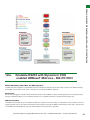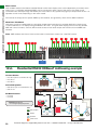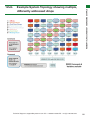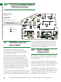
1
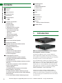
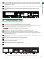
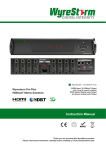
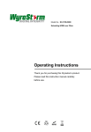
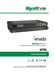
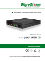
Wyrestorm HDBaseTTM Class D Digital Audio Amplifier / Receiver / Repeater
Part Number
AMP-001-010
Instruction Manual
Thank you for choosing this WyreStorm product.
Please read these instructions carefully before installing to avoid complications later.
Technical Support: [email protected] US: +1 866 677 0053 EU: +44 (0) 1793 230 343
1
CONTENTS AND INTRODUCTION
Contents
13 EDID Management
i. About EDID
ii. Before EDID adjustment
iii. EDID Pre-sets
1
Introduction
2
Features
14 Troubleshooting
3
Safety Precautions
4
Package Contents
15 FAQ’s
5
Specifications
6
Panel Descriptions
i. Front
ii. Rear
7
Connection and Operation
i. Cabling Guide
ii. RJ45 Termination
iii. Initial Connection
iv. IR/RS232 Control Connection
v. Optional Device Connection
- Personal Device Audio Input
- Speaker Connection
- Subwoofer
- External Power Amplifier
- Supported Speaker Types
vi. Interface Device
8
Basic Operation
9
Remote Control Handset Operation
16 Maintenance
17 Provided Service
18 Mail In Service
19 Warranty
i.
Warranty Limits and Exclusions
20 Installation Notes
1.
Introduction
10 Onscreen User Interface
11 Application Scenarios and installation benefits
i. Basic Centralized Source
ii. Extended Centralized Source
iii. Basic Matrix
iv. Extended Matrix
v. AMP-001-010 as Display Receiver
vi. AMP-001-010 as In-line Solution
vii. Central Configuration
12 RS232 Application Scenarios
i. Understanding RS232 Connection & Signals
ii. Zonal IR for Cascading Multiple Independently
Controlled AMP units
iii. Global IR for Cascading Multiple Collectively controlled
AMP units
iv. Hybrid IR for combination of Zonal and Global IR
control of multiple AMP units
v. RS232 Addressing
vi. Routable RS232 with Wyrestorm POH-enabled
HDBaseT Matrices - MX-PP-POH
vii. Residential RS232 HDBaseT Addressing example
viii. Example system topology showing multiple, differently
addressed amps.
ix. Commercial RS232 HDBaseT Addressing example
2
AMP-001-010 Wyrestorm HDBaseTTM Class D Digital
Audio Amplifier / Receiver / Extender
The Wyrestorm AMP-001-010 is a unique HDBaseTTM
Class D digital audio amplifier with receiving and repeating
functionality that fundamentally changes the way to approach
the design of multi-room audio-visual systems.
Fully cascadable (daisy-chained) over multiple 70m/230ft
distances up to 7 times using a single Cat5e cable to create
larger distributions. It also offers HDMI/HDBaseT reception
and pass-thru, 2.1 audio amplification with subwoofer and
stereo preouts for connection to an AVR and HDMI breakout
with bidirectional control of source/display from either
location via IR/RS232.... and so much more.
Feature rich and highly versatile, the AMP simplifies,
combines and improves the relationship between HDMI,
HDBaseT and stereo audio for integrators by incorporating
3:1 audio switching from centralized AV sources and ARC or
local audio input.
Technical Support: [email protected] US: +1 866 677 0053 EU: +44 (0) 1793 230 343
USB to 5V Cable
Part Number CAB-USB-5V
• Conforms
to IEEE-568B
standards
Employing
a switching
topology,
the low voltage, energy
efficient digital Class D amplification delivers power to the
• Each HDMI port also supports DVI signals.
speaker load exclusively with very little power wasted in
• Each Output
port can be
fed to multiple
displays
operation.
This increase
in efficiency
has the
main (cascaded).
benefit
of• lowering
heat
dissipation
and
reducing
the
size
of
the
Enables up to 4 HDMI video/audio devices to be independently
amplifier
assembly.
If
properly
executed,
most
D-class
switched through up to 4 HDMI displays or projectors for
amplifiers
typically digital
have adistribution.
much smaller form factor and a
uncompressed
lower BOM cost than comparable Class-A/AB/B units.
• Each output able to show any connected source simultaneously
regardless
of whether
the input
carries
HDCP
encryption.
In terms
of installation,
it can
be used
locally
in-room
as a
• Options range from basic control of devices using IR TX and RX ports
• toFully
to further
lengthen
transmission.
fullycascadable
integrated control
via leading
control
systems using RS232.
• Commands (Tx, Rx, Gnd) sent with HD Audio & V ideo contained
*NOTE: ideal conditions denote cable run is within
within a single Cat5e/6
specified
distance range of product, no electrical
• AMPs addressable via RS23 • RS232 Port for firmware update or
interference, the use of straight cable runs with no bends
signal transmission.
orRS232
kinkscontrol
and no
patch panels or wall outlets used. Please
• EDID management and pre-sets via DIP switch.
be advised that the presence of any of these factors in
• LED indication – power status, audio source selection (HDBaseT,
your installation may compromise bandwidth and signal
Local or ARC).
strength.
For longer transmission distances, RS232 control
• HDMI v1.4 features supported.
and Ethernet pass-through, please see our full HDBaseT
• HDCP compliant.
or HDBT Lite range of matrices, transmitters, receivers and
• Internal ESD protection.
extender sets.
• Compact size for flexible integration location.
• Mounting brackets supplied.
display
device,
remotelyInstall
in-rack
centrally
at any
point in• Refined
for Custom
andorHome
Theatre
Installations.
line for one of the most flexible and powerful applications of
• Reads and
copies EDID
from connected devices with additional
HDBaseT
technology
to date.
EDID configuration through customisable DIP switch settings if
Thenecessary.
AMP-001-010 is the first product of its kind and
represents
Wyrestorm’s
innate understanding and
• 2k resolution
supported.
appreciation of the AV installation by continually pushing the
• Fully 3D of
compatible
– Frameto
sequential
3D (Blu-ray)
and
boundaries
what is possible
offer innovative
products
interlaced
stereoscopic
3D
(satellite
broadcasts
etc.)
that add great value to any residential or commercial
application,
the sizeresolutions
or budget.up to and including
• Supportswhatever
all high definition
3.3. Safety
SafetyPrecautions
Precautions
1080p and standard video formats.
www.wyrestorm.com
• RS232 port.
Part Number
AMP-001-010
• Choose
from 6 switching
modes – infrared remote control, front
panel buttons, local IR, IR call-back, LAN and RS232.
2.
Features
• Simple switching remote control included, which can also be
learned into a universal remote handset to allow the control of
multiple devices from one handset.
• Fully compatible for integration with market leading control systems.
• Combined HDBaseT Repeater, Receiver and Class D Amplifier – all in
•one.
4 x IR 3.5mm mini-jack ports for each output to link IR from
control system to control display
• Compact and easy to install & use with single Cat5e/6 cabling –
the same
basicextension
integrationport
principles
for residential,
light or
•applies
Additional
infrared
for longer
IR connections
major commercial projects.
• HDMI v.1.3
• Flexible and versatile – multitudes of application scenarios from basic
to complex
volume
digital AV distribution installed at any
•extender
Supports
24Bit Colour
depth
point during a cable run.
• Signalling rate of 6.75 Gbps
• HDBaseT Input and pass-thru with HDBaseT Output.
• •3:1Pack
Audio
Switcher/Receiver
– Audio
from
centralized
source
comes
complete with
1 x 4x4
Matrix
with 19”
rackvia
HDBaseT
Transmitter
Device,
Return
ChannelIR
(ARC)
brackets,
4 x 40m or
IR Matrix
receivers
withAudio
mounting
brackets,
orreceivers,
Local Audio
Input via
3.5mm.
emitters
and
a Matrix remote control handset.
• AMP used centrally with AV source, In-line near speakers, wall
Additional features included on the RX-1UTP-IR-40
mounted near data connections or locally at display location.
Transmitstransmission
one-way signal
together
withdevice
the HDMI
signal
over a
• •70m/230ft
distance
between
and AMP
> then
single70m/230ft
Cat5e/6/7
another
to cable.
next AMP.
• Fully cascadable up to 7 times from single transmitting device (Matrix
• Receivers capable of 1080p transmissions up to 40m (131ft)
or HDBaseT transmitter).
under ideal conditions*
• HDMI output for direct connection of HD display either in-line to each
•AMP
Forconnected
even greater
and
finerun.
tuning, each receiver features
or atcontrol
the end
of the
fully adjustable
EQ per
distance
range
for optimising
• 2.1a stereo
audio at 25w
channel
- amplifier
capabilitythe
to drive
signal.loads.
4, transmission
6 & 8 Ohm speaker
• High quality preamplifier adjustment for tone/volume/sub/mute
control.
Technical Support: [email protected] US:
• Variable Analog line level outputs.
• Analog (RCA) Subwoofer output.
• Stereo speaker amplified outputs with left/right spring terminal
connections.
• Bidirectional control of source and display via IR or RS232 (IR control
signal passed within HDMI transmission).
WARNING
WARNING
reduce
theofrisk
fire, electric
To To
reduce
the risk
fire,ofelectric
shock shock
or or
product
damage:
product
damage:
1. DoDo
expose
apparatus
to rain,
moisture, sprays,
1.
notnot
expose
thisthis
apparatus
to rain,
moisture,
drips
or
splashes
and
ensure
that
no
objects
containing
sprays, drips or splashes and ensure that no
.
liquids are placed on the apparatus, including cups,
objects containing liquids are placed on the
glasses and vases.
apparatus, including cups, glasses and vases.
2. Do not place this unit in a confined space such as
or bookshelves.
2. Doenclosed
not placeshelving,
this unit cabinets
in a confined
space such asEnsure the
unit
is
adequately
ventilated.
enclosed shelving, cabinets or bookshelves.
the unit
adequately
ventilated.
3. Ensure
To prevent
theis risk
of electric
shock or fire hazard due to
overheating, do not cover the unit or obstruct ventilation
with
newspaper,
cardboard
3. Toopenings
prevent the
riskmaterial,
of electric
shock or fire
hazard or
anything
that maydo
restrict
airflow
due
to overheating,
not cover
theinto
unit the
or unit.
openings
4. obstruct
Do notventilation
install near
externalwith
heatmaterial,
sources such as
newspaper,
or anything
may
restrict
radiators, cardboard
heat registers,
boilers that
or any
device
that
airflow
into the
unit.
produces
heat
such as amplifiers or computers and do
not place near sources of naked flame.
4.
not install
near external
heat sources
aslightening
5. DoUnplug
apparatus
from power
supply such
during
radiators,
heat
registers,
boilers
or
any
device
that
storms or when unused for long periods of time.
produces heat such as amplifiers or computers and
6. Protect the power cable from being walked on, pinched
do not place near sources of naked flame.
or restricted in any way, especially at plug connections.
7. Unplug
Only use
attachments/accessories
specified by the
5.
apparatus
from power supply during
manufacturer.
lightening storms or when unused for long periods
time. contain non-servicable parts - Refer all servicing to
8. of Units
qualified service personnel.
6. Protect the power cable from being walked on,
pinched or restricted in any way, especially at plug
+866 677 0053 EU: +44 (0) 1793 230 343
connections.
4
7. Only use attachments/accessories specified by the
manufacturer.
8. Units contain non-servicable parts - Refer all
servicing to qualified service personnel.
Technical Support: [email protected] US: +1 866 677 0053 EU: +44 (0) 1793 230 343
3
FEATURES AND SAFETY
FEATURES AND SAFETY PRECAUTIONS
• Simplified ports - Input: HDMI – Output: integrated RJ45
connectors for a single Cat5e/6/7 UTP cable to each display
point for ease of installation.
PACKAGE CONTENTS, SPECIFICATIONS AND PANEL DESCRIPTIONS
4.
Package Contents
1 x AMP-001-010 HDBaseT Digital Amplifier main unit
1 x Remote control handset
1 x Printed product manual
2 x Installation brackets (recommended)
(also downloadable at www.wyrestorm.com)
1x USB - Serial Cable (pheonix connector)
1 x USB flash drive containing control software and digital
product manual
1 x 18v DC power supply
1 x IR TX transmitter
1 x IR RX receiver
5.
Specification
6i.
Panel Description - Front
1
Amplified passive speaker output with spring terminal connections - Connecting minimum power handling of 25
Watts RMS per channel accepting 4, 6 or 8 Ohm impedance.
2
Analog Subwoofer Pre-out for external connection of active sub woofer accepting single Mono/LFE RCA Input.
3
RS232 serial control port – for direct and local control of AMP through third party control systems or PC.
Software provided for connection to a control system - see www.wyrestorm.com for protocols for leading
Control Systems.
4
HDBaseT IN – HDBaseT input accepting full HD video, HD audio and control signals from centralized source
over a single Cat5e/6.
4
Technical Support: [email protected] US: +1 866 677 0053 EU: +44 (0) 1793 230 343
Pre-out Stereo Audio Output (DAC > Digital Analog Converter) for direct connection to external amplifier/AVR
via stereo RCA cables (Note: when external power amplification is used, speakers and Subwoofer should be
connected directly to the AVR).
6
IR RX control receiver port - for receiving infrared control signals and sending back to centralized source & AMP
function control.
7
IR TX control transmitter port - For transmitting infrared control signals from central location to control TV
function.
1
6ii.
2
3
4
5
6
7
Panel Description - Rear
1
Power ON/OFF switch – lit when powered (standby via remote control handset)
2
HDBaseT output – repeats HDBaseT transmission a further 70m/230ft to another AMP-001-010 or RX-1UTPIR-70 receiver to end the distribution, including embedded IR/RS232 commands.
Attention: Maximum number of AMPs that can be daisy-chained is 7
3
HDMI output – for connection to a local HDMI display device, including ARC return path
4
EDID DIP Switch – manual EDID management enables immediate EDID data feedback to the display to
overcome any communication issues encountered between connected devices - includes 3D and Long cable
mode (see EDID settings section)
5
Audio Source Select button – press to manually toggle through local audio, ARC or HDBaseT audio sources (Lit
for selected)
6
Audio Source LED indication – displays currently active audio source.
7
Audio selected – 2ch stereo or 2.1ch stereo audio selected
8
IR status – confirms IR receiver activity
9
L/R Line level local audio source input – 3.5mm mini jack
10 18vDC Power input – screw-lock connector (please use power supply provided)
1
2
3
4
5
6
7
8
9
10
Technical Support: [email protected] US: +1 866 677 0053 EU: +44 (0) 1793 230 343
5
PANEL DESCRIPTION REAR
5
CONNECTION & OPERATION - CABLING GUIDE
7i.
Connection & Operation - Cabling Guide
Multiple Inputs via MX0808-PP with additional
Local audio input & ARC
Local Audio
Source
HDMI/
ARC
Full 1080p HD Audio
Video from
centralized source
via Cat5e/6
IR Transmitter
IR Control
70m/230ft Single Cat5e/6
RS232
RS232
AMP-001-010
1. AV Source>
2. ARC>
3. Local Input>
IR Receiver
18V
Multiple HDMI
Audio/Video Sources
Extended Multiple Inputs
Local Audio
Source
HDMI/
ARC
Full 1080p HD Audio
Video from
centralized source
via Cat5e/6
IR Transmitter
IR Control
70m/230ft Single Cat5e/6
RS232
RS232
AMP-001-010
1. AV Source>
2. ARC>
3. Local Input>
IR Receiver
18V
Multiple HDMI
Audio/Video Sources
70m Single
Cat5e/6
Local Audio
Source
1080p
AMP-001-010
1. AV Source>
2. ARC>
3. Local Input>
6
Local Audio
Source
HDMI/
ARC
IR Receiver
IR Control
70m/230ft Single Cat5e/6
RS232
1080p
HDMI/
ARC
IR Receiver
AMP-001-010
1. AV Source>
2. ARC>
3. Local Input>
Technical Support: [email protected] US: +1 866 677 0053 EU: +44 (0) 1793 230 343
HDMI/
ARC
Local Audio
Source
AV Source
IR Receiver
IR Control
HDMI
TX-IR-70
CONNECTION & OPERATION - CABLING GUIDE
Full 1080p HD Audio
Video from
centralized source
via Cat5e/6
AMP-001-010
1. AV Source>
70m/230ft Single Cat5e/6
2. ARC>
3. Local Input>
RS232
IR Transmitter
Extended Multiple Inputs
Local Audio
Source
AV Source
IR Control
HDMI
TX-IR-70
70m/230ft Single Cat5e/6
RS232
RS232
HDMI/
ARC
Full 1080p HD Audio
Video from
centralized source
via Cat5e/6
AMP-001-010
1. AV Source>
2. ARC>
3. Local Input>
IR Receiver
18V
IR Transmitter
70m Single
Cat5e/6
Local Audio
Source
1080p
Local Audio
Source
HDMI/
ARC
AMP-001-010
1. AV Source>
2. ARC>
3. Local Input>
IR Receiver
IR Control
70m/230ft Single Cat5e/6
RS232
1080p
HDMI/
ARC
AMP-001-010
1. AV Source>
2. ARC>
3. Local Input>
IR Receiver
Technical Support: [email protected] US: +1 866 677 0053 EU: +44 (0) 1793 230 343
7
AMP-001-010 Centralized with Wyrestorm Matrix with managed Lip Sync
CONNECTION & OPERATION - CABLING GUIDE
Speaker Cable to In-Ceiling Speakers
AMP-001-010
18V
Cat5e/6
HDMI
70m Single Cat5e/6
Full 1080p HD Audio
Video from
centralized source
via Cat5e/6
RX-IR-70
AMP-001-010 In-line adjacent with In-Ceiling speakers
Speaker Cable to
In-Ceiling Speakers
TX-IR-70
70m Single
Cat5e/6
18V
AMP-001-010
HDMI
70m Single
Cat5e/6
Full 1080p HD Audio
Video from
centralized source
via Cat5e/6
RX-IR-70
AMP-001-010 In-Line and Cascaded with In-Ceiling Speakers
TX-IR-70
Speaker Cable to
In-Ceiling Speakers
70m Single
Cat5e/6
18V
AMP-001-010
70m Single
Cat5e/6
18V
AMP-001-010
HDMI
70m Single
Cat5e/6
Full 1080p HD Audio
Video from
centralized source
via Cat5e/6
RX-IR-70
Speaker Cable to
In-Ceiling Speakers
AMP-001-010 as a Receiving Display Device
HDMI
18V
Full 1080p HD Audio
Video from
centralized source
via Cat5e/6
AMP-001-010
70m Single Cat5e/6
Speaker Cable to
In-Ceiling Speakers
8
Technical Support: [email protected] US: +1 866 677 0053 EU: +44 (0) 1793 230 343
RJ45 Termination
Cat5e Wiring Guide
The quality of termination for every RJ45 is essential.
Poor terminations leads to intermittent performance
and longer install times
an HDBaseT repeater to extend the transmission
as well as a Receiver, with the inclusion of up to
7 units connected along a single cable run. As
such, an RX-1UTP-IR-70 receiver is only required
to extend the final leg of the distribution a further
70m/230ft, or if HDMI output and IR/RS232 control
only is required.
5
As before, connect the HDMI sink ( such as High
Definition LED/Plasma flat panel display or HD Digital
projector) to the HDBaseT Output of the HDBaseT
Receiver device.
HDBaseT Class D Digital Audio Amplifier / Receiver / Repeater
AMP-001-010
7iii.
Initial Connection
1 Connect an HDMI input (such as DVD, Blu-Ray,
PS3, Satellite, Cable, media server, computer etc.) to an
HDBaseT transmission source (such as a Wyrestorm TX1UTP-IR-70 transmitter or a MX-PP matrix solution).
2
Connect a good quality, well terminated Cat5e/6
cable of no more than 70m/230ft between the HDBaseT
output of the HDBaseT transmission device to the
HDBaseT Input of the AMP-001-010
Attention: 70m/230ft is the maximum
recommended transmission distance for this
classification of HDBaseT equipment and denotes
perfect transmission conditions - including straight
cable runs with no electrical interference, bends,
kinks, patch panels or wall outlets. If any of the
above are a factor in your installation, transmission
range may be affected – take care to avoid where
possible.
3
Connect the HDMI sink ( such as High Definition
LED/Plasma flat panel display or HD Digital projector) to
the HDMI Output of the AMP-001-010
4
Connect another well terminated and good quality
Cat5e/6 cable from HDBaseT output of the AMP-001010 to HDBaseT input of a Wyrestorm HDBaseT Receiver
device ( such as an RX-1UTP-IR-70 receiver, or another
AMP-001-010)
Repeat process for all AMP-001-010 units installed along
your cable run.
7iv.
IR/RS232 Control
Connection
1 For two way control of connected sources and
displays from either location, connect IR TX infrared
transmitter emitters to the IR TX ports of the HDBaseT
Transmitter devices and AMP-001-010.
2
Insert IR RX infrared receiver emitters into IR RX
ports of the HDBaseT Receiver devices and AMP-001010.
3
If using an RS232-based control system, insert
cables into the RS232 ports of devices to enable RS232
control signal transmission ( Default set for RS232).
4
Connect the AMP-001-010 to a mains power
source using the 18vDC power supply included.
Attention: The AMP-001-010 is capable of
Power-over-HDBaseT passthrough distances up
to 50m/164ft when used between PoH-enabled
devices such as a MX-PP-POH matrix or POH
transmitters and receivers.
The AMPs themselves will still require mains power
for operation but are able to passthrough power
from a PoH transmission device to a PoH receiver
to negate the need for mains power at the display
end.
Technical Support: [email protected] US: +1 866 677 0053 EU: +44 (0) 1793 230 343
9
RJ45 TERMINATION, INITIAL CONNECTION AND IR/RS232 CONTROL CONNECTION
7ii.
Attention: The AMP-001-010 can be used as both
OPTIONAL DEVICE CONNECTION, INTERFACE DEVICE, BASIC & REMOTE CONTROL OPERATION
7v.
Optional Device
Connection
1
For connection of local line level audio sources
(such as MP3 player, multiroom audio system, laptop/
desktop, smartphone/tablet, mixer, microphone etc)
connect a 3.5mm mini jack from the audio source to the
L/R port of the AMP-001-010
1
Turn on the AMP-001-010 using the POWER switch
on the front panel – LED will indicate power status.
2
Select the AUDIO SOURCE by pressing the SELECT
button – LED will indicate selection
9.
2
To connect stereo speakers directly to the AMP001-010, insert evenly stripped, good quality copper
cable of adequate gauge into the SPEAKER spring
terminal connections of the AMP-001-010 with care
taken to insert wires into correct spring clips based on
audio signal polarity (+/+, -/-).
Ensure plastic insulation is undamaged and cable is
untangled, without bends or kinks that may interfere with
transmission.
Remote Control
Handset Operation
Attention: Maximum output available 25w per
channel
1
2
3
4
5
6
7
3 For increased bass range, an active subwoofer can
be connected to the SUB OUT port of the AMP-001-010
4
For additional amplification, the AMP-001-010
can be connected to an external power amplifier or AV
Receiver (AVR) via the stereo AUDIO OUT ports.
Attention: In such cases where an AVR is
used, the SUB OUT of the AMP-001-010 should
be connected to the SUB Input of the AVR and
a subwoofer connected to the AVR. Likewise,
speakers should be connected directly to the AVR
rather than the spring terminal connectors of the
AMP-001-010.
7vi.
Interface Device
Using the Audio Pre-Out you can connect the AMP to
a multi-room audio amplifier system or seperate power
amplifier, and expand beyond a basic stereo pair.
8.
Basic Operation
The AMP-001-010 can be controlled locally via the front
panel or remotely using the handset provided or an
RS232 third party control system.
10
1
Toggle standby mode to power down unit when not
in use.
2
Toggle mute function temporarily disables audio
output
3
Bass Control button, enable/disable internal cross
over to route bass signals to sub pre-out or main speaker
output.
4
Source selection to output audio from the main
HDBaseT input, local input jack or ARC from locally
connected TV.
Attention: TV must have ARC function and be
connected to the relevant HDMI port
5
Increase/decrease main speaker volume. This does
not control the line level pre-out, this is a fixed output.
6
Adjust output level of subwoofer pre-out port.
7
EQ selection buttons to equalize audio signal
depending on your taste.
Technical Support: [email protected] US: +1 866 677 0053 EU: +44 (0) 1793 230 343
Onscreen User Interface
ONSCREEMN USER INTERFACE
10.
1
3
4
2
10
6
5
7
8
9
Attention: Amps must be individually connected
and have their addresses assigned first, before
installation.
4
Click the Right Arrow ‘>’
The ‘Address’ should show up under ‘selected addr’
5
Connect the (provided) RS232 cable to a laptop Via USB
port to Determine the COM Port
If there is no TV/Display connected to the AMP
‘Audio Only’ needs to be clicked
Com Port Connection Status
On opening the User Interface, press Connect to
establish a connection with assigned AMP units and
control settings. Connection status is illustrated by text
colour/selection icon - when connected, the only option
will be to press Disconnect and vice versa.
6 EQ can be set manually to Normal, Pop, Classic,
Metal, Jazz, or Rock
1
Connecting AMP via USB or Serial
The COM Port setting within the AMP software must
match the COM Port that your PC has assigned to the
USB - Serial Cable.
2
Designate an Address for each Amp that will be
connected to the system. Choose a number between 0
and 19 to be the address and click “Write Addr”
3
Click Search Address
The ‘Address’ you typed in should populate under ‘All
Addr’
7
Audio can be switched manually to HDMI Source,
HDMI ARC or Local L/R
8
EDID can be set manually to Copy HDMI, Copy
HDBaseT, Fix 3D 2CH or Fix 2D 2CH
9
Lip sync can be set manually to Bypass, Delay 1 or
Delay 2
10 Master Volume, Sub Volume Balance,Treble
and Bass can all be set manually
Slide Volume Bar & Click ‘Volume Set’
Slide SUB Volume Bar & Click ‘Volume Set’
Slide Balance Bar & Click ‘Balance Set’
Slide Treble Bar & Click ‘Treble Set’
Slide Bass Bar & Click ‘Bass Set’
Technical Support: [email protected] US: +1 866 677 0053 EU: +44 (0) 1793 230 343
11
AMP-001-010 APPLICATION SCENARIOS - BASIC AND EXTENDED CENTRALIZED SOURCE
11i.
Application Scenarios and Installation Benefits
- Basic Centralized Source
AMP as Cat5e Extender/Receiver
No compromise in extender performance – 1080p 36Bit
The most progressive extender solution currently
available
Overcome your competitors with a better solution
IR rx
RX
ir
Huge up-sale opportunities from conventional
extender product
Higher Value, Add Speakers, Subs, Cables to increase
profit
11ii.
18Vpsu
PSU
18v
cat5e/6
Cat5e/6
TX-70
Sending IR to display from a control system
Useful for screen functions such AV
Input, ARC selection or power
functions via a control system
IR TX
ir
tx
HDMI with
ARC
hdmi
with
arc
HDMI
hdmi
IR T
ir
tx
IR RX
ir
rx
Extended Centralized Source
HDBaseT Output Connection
Amp functions as transmitter and receiver to enable up
to 7 AMPs to be cascaded within a single zone using
HDBaseT Out to HDBaseT In ports on units.
Access to Central and Local Source
Each Amp has access to a central source, whether a
matrix switcher or a single HDMI input via an HDBaseT
Transmitter, also maintains its own personal audio and
ARC Inputs.
using hdbaset out to
cascade central
source to other amps
HDBT out
hdbt
out
Maintain Central Source Control
Central Source Control is achieved with IR Receivers at
each display.
HDBT in
IN
hdbt
Cat5e/6
cat5e/6
IR rx
RX
ir
18Vpsu
PSU
18v
HDMI with
ARCarc
hdmi
with
HDMI
hdmi
TX-7
IR
irTX
tx
local audio only
source maintained
between amp & display
ir control of
central source
still maintained
HDBT out
out
hdbt
HDBT IN
hdbt
in
IR rx
RX
ir
PSU
18v18V
psu
HDMI with
ARC
hdmi
with
arc
12
HDBT out
hdbt
out
HDBT IN
hdbt
in
IR rx
RX
ir
18Vpsu
PSU
18v
HDMI with
ARCarc
hdmi
with
70m/230ft Single Cat5e/6
between each AMP to
Continue Transmission
7 AMP devices supported
by a transmission device
(TX or Matrix) enable
distribution spanning
distances of up to
560m/1840ft along a single
output.
Technical Support: [email protected] US: +1 866 677 0053 EU: +44 (0) 1793 230 343
Basic Matrix
BASIC MATRIX AND EXTENDED MATRIX
11iii.
4x4, 6x6, 8x4 or 8x8 Pro Plus Matrix Solution
Add 4, 6 or 8 centralized sources while maintaining full AMP integration as
a Amplifier, Receiver, Transmitter and repeater for even greater flexibility for
residential and commercial applications.
HDBaseT Output on Each Matrix Output
Same cable transmission as a basic single source system,
with the same advantages of HDBaseT technology… multiplied.
AMP as HDBaseT Receiver…
and Then Some
Each AMP performs the same transmission
hdmi
receiving functions of centralized sources as
an RX70-IR-PP Display Receiver, but adds
ARC, personal audio input, Stereo breakout
to local amplification and 2.1 audio breakout for
greater options at the display end.
IR rx
RX
ir
18V
PSU
18v
psu
Cat5e/6
cat5e/6
HDMIwith
with ARC
hdmi
arc
HDMI
hdmi
HDMI
Personal Audio Connection with Overlay
Local audio input can overlay the central source video for additional audio options, such as internet radio sports
commentary over a live satellite broadcast, or jukebox over TV news or a Blu-Ray movie.
Same IR receiver function
IR receiver “eye” on displays now handles
AMP function, matrix switching function & central source control.
11iv.
Extended Matrix
using hdbaset out to
cascade central
source to other amps
As Easy as Single Source Transmission
The same principle as a single source with a single transmitter,
but with the matrix multiplying that process for multiple outputs.
HDBT out
out
hdbt
IR rx
RX
ir
HDBT
hdbtIN
in
18Vpsu
PSU
18v
HDBaseT Output on Each Amp
Extend distribution as AMPs also function as a repeater to
transmit signals a further 70m/230ft to the next Amp in the
chain, then another, and another...
IR RX at Display Location
Control of all multiple sources, AMP functions
and matrix control at each display location.
Larger Distribution
With 7 AMPs per matrix output, a
network of up to 56 screens is easily
achievable with an 8 output Pro Plus
matrix, each with localized amplification
and personal audio input where needed.
hdmi with arc
using hdbaset out to
cascade central
source to other amps
HDBT out
out
hdbt
Cat5e/6
cat5e/6
IR rx
RX
ir
HDBT IN
hdbt
in
Cat5e/6
cat5e/6
18Vpsu
PSU
18v
HDMI with
with ARC
hdmi
arc
HDMI
hdmi
HDMI
hdmi
Technical Support: [email protected] US: +1 866 677 0053 EU: +44 (0) 1793 230 343
13
AMP-001-010 AS DISPLAY RECEIVER AND AMP AS IN-LINE SOLUTION
11v.
AMP-001-010 as Display Receiver
AMP as a Receiving Device
Simple installation of the AMP between a transmission transmission device and the display, with local, direct speaker
connection.
Choice of Transmission Device
Single source transmitter or multi-source matrix - the choice is yours - the installation procedure is identical.
Single Cat5e/6 Cable up to 70m/230ft
Delivers full 1080p 36bit HD video to display, high quality digital audio to amplifier, as well as sending and receiving IR
bidirectionally all through HDBaseT.
t5e/6
cat5e/6
transmitting device
mx0808-pp
tx-70-pp
11vi.
HDMI
hdmi
amp as receiving
device
AMP-001-010 as In-line Solution
AMP as an in-line device*
Simple and cost effective solution for distribution incorporating in-wall or in-ceiling speakers between an
EX-1UTP-IR-70 HDBaseT extender set for total distance of 140m/460ft.
Covers Longer Cable Runs
70m/230ft from Transmitter to AMP, then another 70m/230ft from the AMP to the Display Receiver.
AMP Control Maintained
Control of central source and AMP still possible from display Location, including AMP stand-by function.
*ARC not supported in this instance
Audio Only
digital transmission over longer cable runs >>> rs232 to amp
18Vpsu
PSU
18v
Audio Only
Audio/Video
digital transmission over longer cable runs
Ceiling
Ceiling
EX-1UTP-ir-70
(rx)
EX-1UTP-ir-70
(tx)
hdmi
IR TX
ir
Rx
hdmi
14
Technical Support: [email protected] US: +1 866 677 0053 EU: +44 (0) 1793 230 343
Central Configuration
AMP Located Centrally*
AMP can be positioned at a central point, such as a rack, and connected to the transmission
device via a short patch lead.
Delay Set
BypassD
elay 1
Status
Delay 2
MUTE
Managed Lip Sync Set Via PC
As mixing analog audio and digital video can often cause sync issues, the AMP
contains settings and software to overcome such difficulties.
*ARC not supported in this instance
Rx-70-ir-pp
IR rx
RX
ir
(arc
notsupported)
supported)
hdmihdmi
(arc
not
0.5mpatch
patch lead
0.5m
lead
up to
8 different
av sources
up
to
8 different
av sources
HDMI
hdmi
12i.
HDMI
hdmi
RS232 Application Scenarios - Understanding
RS232 Connection & Signals
RS-232C, EIA RS-232, or simply RS-232, refers to the same standard defined by the Electronic Industries Association
in 1969 for serial communication.
DTE and DCE
DTE stands for Data Terminal Equipment. A computer or control system is DTE and connects to Data Communication
Equipment, or DCE such as an AMP, matrix or modem.
DTE equipment typically feature a Male Connector, while DCE contain a Female Connector, although that is not always
true - a simple way to confirm is to measure Pin 3 and Pin 5 of a DB-9 Connector with a Volt Meter, if a voltage of -3V
to -15V is achieved, the device is DTE. If the voltage is on Pin 2, then the device is DCE.
Note: The result for a DB-25 Connector is reversed (Please refer to DB-9 to DB-25 conversion table)
RS-232 Pin outs (DB-9)
1 2 3 4 5
6 7 8 9
A male DB-9 connector viewed from the front.
Reverse or back view of male connector for
Female Connector.
DB-9 to DB-25 Conversion
DB-9
DB-25
1
2
3
4
5
6
7
8
9
8
3
2
20
7
6
4
5
22 Function
DCD
RxD
TxD
DTR
GND
DSR
RTS
CTS
RI
Data Carrier Detect
Receive Data
Transmit Data
Data Terminal Ready
Ground (Signal)
Data Set Ready
Request to Send
Clear to Send
Ring Indicator
Technical Support: [email protected] US: +1 866 677 0053 EU: +44 (0) 1793 230 343
15
CENTRAL CONFIGURATION AND UNDERSTANDING RS232 CONNECTION & SIGNALS
11vii.
UNDERSTANDING RS232 CONNECTION & SIGNALS
DTE Pin Assignment (DB-9)
1
2
3
4
5
6
7
8
9
DCD
RxD
TxD
DTR
GND
DSR
RTS
CTS
RI
Data Carrier Detect
Receive Data
Transmit Data
Data Terminal Ready
Ground (Signal)
Data Set Ready
Request to Send
Clear to Send
Ring Indicator
DCE Pin Assignment (DB-9)
1
2
3
4
5
6
7
8
9
DCD
TxD
RxD
DSR
GND
DTR
CTS
RTS
RI
Data Carrier Detect
Transmit Data
Receive Data
Data Set Ready
Ground (Signal)
Data Terminal Ready
Clear to Send
Request to Send
Ring Indicator
RS-232 Connections
A straight-through cable should be used to connect a DTE (e.g. computer) to a DCE (e.g. AMP, matrix or modem), with
all signals from one side connected to the corresponding signals on the other side in a one-to-one basis.
A crossover (null-modem) cable can be used to connect two DTE directly, without a modem in between to cross
transmit and receive data signals between the two sides. There are numerous variations on how control signals are
wired:
Straight-through (DB-9
(DTE) (DCE)
1
DCD -------DCD 1
2
RxD ------- TxD
2
3
TxD
------- RxD 3
4
DTR ------- DSR 4
5
GND ------- GND 5
6
DSR ------- DTR 6
7
RTS ------- CTS 7
8
CTS ------- RTS 8
9
RI
------- RI
9
Mark (1)
space (0)
LSB
start
Crossover (Null-Modern) (DB-9
(DTE) (DCE)
1
DCD -------DCD 1
2
RxD ------- TxD
3
3
TxD
------- RxD 2
4
DTR ------- DSR 6
5
GND ------- GND 5
6
DSR ------- DTR 4
7
RTS ------- CTS 8
8
CTS ------- RTS 7
9
RI
RI
9
MSB
0 1 2 3 4 5 6 7
stop
-12v
+12v
RS-232 Logic Waveform (8N1)
The graphic above illustrates a typical RS-232 logic waveform (Data format: 1 Start bit, 8 Data bits, No Parity, 1 Stop
bit). The data transmission starts with a Start bit, followed by the data bits (LSB sent first and MSB sent last), and ends
with a “Stop” bit.
The voltage of Logic “1” (Mark) is between -3VDC to -15VDC, while the Logic “0” (Space) is between +3VDC to
+15VDC.
RS-232 connects the Ground of 2 different devices together, which is the so-called “Unbalanced” connection. An
unbalanced connection is more susceptible to noise, and has a distance limitation of 15m/49ft.
16
Technical Support: [email protected] US: +1 866 677 0053 EU: +44 (0) 1793 230 343
Zonal IR for Cascading Multiple Independently
Controlled AMP units
ZONAL IR AND GLOBAL IR CONTROL
12ii.
Individual IR Receivers for Independent Operation
Independent Zonal IR control is possible for individual, daisy-chained AMPs using separate IR receivers at display
points.
Full Control of Each and Every Amp
Individual IR Receivers enables commands to be sent to AMPs separately.
Cat5e/6
cat5e/6
zoned ir
each zone with its
own ir receiver
each amp working
independantly
zoned ir
each zone with its
own ir receiver
each amp working
independantly
HDBTout
out
hdbt
HDBT out
out
hdbt
IR rx
RX
ir
18Vpsu
PSU
18v
IR rx
RX
ir
HDBT in
IN
hdbt
HDMI with
with ARC
hdmi
arc
12iii.
18Vpsu
PSU
18v
HDMIwith
with ARC
hdmi
arc
Global IR for Cascading Multiple Collectively
controlled AMP units
Collective Control with a single IR Receiver, Only Final AMP with IR Receiver
Global IR control of a group of AMPs by All AMPs working together in terms of volume commands
Toggle Switch Control for ARC and Personal Audio Input
Cat5e/6
cat5e/6
Cat5e/6
cat5e/6
global ir. all amps
controlled together
from display at the
end of the chain
HDBT out
out
hdbt
global ir. all amps
controlled together
from display at the
end of the chain
remote controlling
master volume for all
amps
HDBT out
hdbt
out
Rx-70-ir-pp
18Vpsu
PSU
18v
HDMIwith
with ARC
hdmi
arc
hdbt in
IR rx
RX
ir
HDBT in
IN
hdbt
18Vpsu
PSU
18v
HDMI with
with ARC
hdmi
arc
hdmi (arc not supported)
Technical Support: [email protected] US: +1 866 677 0053 EU: +44 (0) 1793 230 343
17
HYBRID IR AND RS232 ADDRESSING
12iv.
Hybrid IR for combination of Zonal and
Global IR control of multiple AMP units
Final IR Receiver has overall control of all AMPs albeit with variations
Each AMP has local IR Control
Cat5e/6
cat5e/6
Cat5e/6
cat5e/6
global ir. all amps
controlled together
from display at the
end of the chain
HDBT out
out
hdbt
global ir. all amps
controlled together
from display at the
end of the chain
remote controlling
master volume for all
amps
HDBT out
hdbt
out
IR rx
RX
ir
Rx-70-ir-pp
IR rx
RX
ir
hdbt in
18Vpsu
PSU
18v
HDMIwith
with ARC
hdmi
arc
IR rx
RX
ir
HDBT in
IN
hdbt
18Vpsu
PSU
18v
HDMI with
with ARC
hdmi
arc
hdmi (arc not supported)
12v.
RS232 Addressing
RS232 Addressing
Each AMP can be addressed so serial commands can be sent over HDBaseT to control specific AMPs at specific
display points.
Software Solution
Control commands are sent from PC control software or a control system via the AMP RS232, ensuring correct COM
port selection.
Choice of Control
Each AMP can be set up with individual or group addresses to enable control of a single AMP or group of AMPs.
rs232
Cat5e/6
cat5e/6
Cat5e/6
cat5e/6
amp set to
address 1
amp set to
address 1
amp set to
address 2
HDBT out
out
hdbt
IR rx
RX
ir
18V psu
PSU
18v
HDMIwith
with ARC
hdmi
arc
18
IR rx
RX
ir
HDBT IN
hdbt
in
18v psu
HDMIwith
with ARC
hdmi
arc
IR rx
RX
ir
HDBT IN
hdbt
in
18v psu
HDMI with
ARC
hdmi
with
arc
Technical Support: [email protected] US: +1 866 677 0053 EU: +44 (0) 1793 230 343
ROUTABLE RS232 WITH WYRESTORM POH ENABLED HDBASET MATRICES
12vi.
Routable RS232 with Wyrestorm POH
enabled HDBaseT Matrices - MX-PP-POH
MX-PP-POH Range offers More for AMP Integration
The MX-PP-POH range are customizable Pro Plus matrices in 8x8 and 16x16 that offer a choice of 8 different analog
and digital transmission cards, each converting to 70m/230ft HDBaseT Outputs.
More Power
As the name suggests, the MX-PP-POH feature Power-over-HDBaseT outputs, enabling power to be passed directly
along the Cat5e/6 cable to a PoH-enabed receiver so no additional power is required at the display end.
AMP PoH Passthru
The AMP can be used as an PoH passthru device for power from a PoH matrix or transmitter to be carried to the PoH
display receiver, but in this case the distance of PoH passing through the AMP is restricted to 50m/164ft. All functions
of the AMP are maintained but the Amp itself requires mains power for operation.
Technical Support: [email protected] US: +1 866 677 0053 EU: +44 (0) 1793 230 343
19
RESIDENTIAL RS232 HDBASET ADDRESSING EXAMPLE
More Control
PoH-enabled matrices also feature routable RS232 to allow each display zone to be independently controlled, which
means up to 7 individually addressed AMPs can be connected to each output of the matrix, with serial control
commands sent centrally through the RS232 port of the matrix to any specific Amp/group of Amps within the 8 or 16
separate control zones, depending on the matrix model.
Commands are simply sent to specific AMPs by their address, and ignored by others with a different address.
What Does This Mean?
Vast arrays of can be created easily by cascading multiple matrix switchers for possible distribution covering over
7.84km/4.86miles to 112 displays using the MX1616-PP-POH. This gives each display point its own fully routable
AMP with control of matrix, sources, ARC and full access to local audio output and functions from the AMP user
interface.
Note: AMP address and Control zone can be noted on the bottom of each unit. See EDID section
amp
amp
amp
amp
amp
amp
amp
amp
amp
amp
amp
amp
amp
amp
amp
amp
amp
amp
amp
amp
amp
amp
l
control
system
12vii.
control
system
Residential RS232 HDBaseT Addressing example
Increase Volume
-> vol 05 64 [64 is command for up]
-> vol 03 64
-> vol 06 64
5
5
Active Sub Speaker
-> bas 02 01 [01 is command for on]
-> bas 01 01
1
M
Set Mute Function
-> mut 02
-> mut 06
6
COMMAND Input Format
->command[space]add[space]variable
3
key:
Amp address
M
matrix
3
6
2
speaker
subwoofer
20
amp
Technical Support: [email protected] US: +1 866 677 0053 EU: +44 (0) 1793 230 343
amp
Example System Topology showing multiple,
differently addressed Amps
Technical Support: [email protected] US: +1 866 677 0053 EU: +44 (0) 1793 230 343
RESIDENTIAL RS232 HDBASET ADDRESSING EXAMPLE
12viii.
21
COMMERCIAL RS232 HDBASET ADDRESSING EXAMPLE AND EDID
12ix.
Commercial RS232 HDBaseT
Addressing example
Mute Command
-> mut 03
3
Volume Down
-> vol 01 01
[01 is command for down]
5
3
3
COMMAND Input Format
->command[space]add[space]variable
3
4
key:
Amp address
M
13i.
matrix
1
1
1
1
EDID Management About EDID
8
2
8
M
7
6
as communication between display and amplifier is the
most important in the system. The effective control and
management of EDID is essential for the success of any
integration, with this being achieved in most cases using
the default setting on the AMP-001-010.
EDID (Extended Display Identification Data) is
data generated from each display in the system to
communicate the capabilities of the device (720p, 2ch
Audio, 1080p, 7.1ch Audio).
13ii.
For communication between devices to be made,
and successful connection achieved, devices must
both request and send the required information. For
example, a display will communicate 1080p capability
with 2ch audio, which the source device will accept and
output the correct format for the display. Problems can
arise when different types of devices such as displays,
sources and amplifiers are used within a system, making
communication between them that much more difficult;
sometimes resulting in connection problems.
Should device communication or compatibility issues be
encountered during installations, please refer to the EDID
DIP settings below.
In such instances EDID needs to be streamlined or guided
for all devices to work together, with equipment such as
the AMP-001-010 perfectly placed to handle this process
22
Before EDID
Adjustments
If the maximum capabilities of the display are known, for
example 3D with 2Ch stereo audio, Matching EDID should
be sent to the AMP-001-010, for example settings for 3D
with 2 Channel Audio is Switch 3 to the down position.
If the specification of the display is not known, simply
copy the EDID from the display to AMP, through the HDMI
connection by selecting Switch 1 to the ON position, with
remaining switches to the off position (up), power cycling
the AMP and you are ready to go.
Technical Support: [email protected] US: +1 866 677 0053 EU: +44 (0) 1793 230 343
EDID Presets
EDID DIP Switch settings
1 (Down):ON
0 (Up): OFF
X: Either position - does not effect function
1 2 3 4
ON
DIP
1 2 3 4
ON
DIP
EDID subject to PC: settings
via DIP switch deactivated
adjustment by PC
(Default Factory Setting)
EDID set to copy HDMI
OUTPUT EDID
1 2 3 4
EDID set to copy HDBaseT
OUTPUT EDID
1 2 3 4
EDID set to fix 1080p 2ch
stereo 3D
1 2 3 4
EDID set to fix 1080p 2ch
stereo 2D
1 2 3 4
EDID subject to DIP switch:
settings via PC deactivated
adjustment by unit DIP switch
ON
ON
ON
ON
DIP
DIP
DIP
DIP
EDID PRESETS
13iii.
Attention: Any change to EDID settings will need
a power down and power up cycle via the power
switch.
For convenience and ease of installation,
on the underside of the AMP-001-010 you
will also find the same EDID DIP settings
as well as areas to write the Address of the
AMP unit and the Control Zone it will be
located in.
Technical Support: [email protected] US: +1 866 677 0053 EU: +44 (0) 1793 230 343
23
TROUBLESHOOTING
14.
Troubleshooting
Generally, the majority of HD distribution installation
issues are either caused by minor connection
errors, communication problems between devices,
or when the transmission of high signal bandwidth
is attempted using insufficient cable. Should you
encounter any technical difficulties when installing
and configuring the matrix, we are confident
solutions can be found by working through the
following troubleshooting checklist before seeking
alternative technical support.
No Picture or poor quality picture
1) Power – are all AMPs, HDBaseT transmitters or
display receivers installed powered both ends? All units
should have their own power source i.e. 18v for the AMP001-010 and 5v for 70m.230ft HDBaseT Transmitters and
Receivers – Please use power supplies included.
Note: Display receivers do not need to be independently
powered if part of an HDBaseT PoH extender set or MXPP-POH Matrix solution – there is a two-core power link
between transmitter and receiver that powers the receiver
at thedisplay end. Non-PoH display receivers can also be
powered via the display USB port by using the USB to 5v
power cable also supplied with this model.
Are all sources definitely powered and firmly connected?
2) If possible, always use test equipment prior to
installation and to troubleshoot any problems.
Signal Generator
Part Number
TTSignal
3) Distance – Is the cable too long for the signal to be
transmitted effectively? The HDBaseT classification used
within the AMP-001-010, transmitters and receivers allow
transmission of 1080p up to 70m/230ft so make sure
the cable distance matches the project requirements and
is well within the maximum transmission distance of the
signal.
Note: If approaching the limits of the transmission
capabilities, transmission should be extended by using
another AMP or receiver to ensure the signal reaches its
destination effectively.
4) Cable Joins – Joins in the cable run or RJ45
connectors can impact on signal strength, resulting in
reduced transmission that may manifest itself in incorrect
picture quality, picture dropping out or a complete lack of
picture
5) Cable Choice and Signal Reduction – Are stranded
patch leads being used as interconnects between patch
panels or wall outlets? CCA (Copper Clad aluminium)
cables being used? These can reduce transmission
rates by up to 40% – we recommend solid core straight
through with minimum connections used wherever
possible.
6) Resolution: Speckles noticed in the picture – If
the resolution of the source is reduced, is the result a
clean and stable picture? If so, this could suggest a
discrepancy between source and display resolution or
a bandwidth capacity issue with the cable. Check that
inputs and outputs share the same resolution and that
thesignal is being successfully transmitted along the cable
run.
Test Monitor
Part Number
TTMONITOR
7) Correct connection – It may seem obvious but
double check all UTP, HDMI, power and IR cables are
connected to the correct ports.
Note: Even a fraction off can be the difference between
aperfect picture and a blank screen. Double check all
connections are firmlymade in the correct ports.
24
Technical Support: [email protected] US: +1 866 677 0053 EU: +44 (0) 1793 230 343
9) Electrical interference – HDBaseT is less susceptible
to interference compared to regular transmissions but
the location of cables and devices should be considered
- could any form of interference be generated? If so,
attempt to remove the source of electrical interference
or move the cable run to decrease the effects of the
interference.
10) Is a picture achieved when connecting the
source directly to the display? If not then the problem
could lie with the input or output device rather than the
means of distribution i.e. the cable, AMP or matrix itself.
11) HDMI lead condition and quality – HDMI cables
and connectors are delicate and can be damaged much
easier than component or coax cable. Furthermore,
lead quality varies dramatically, particularly in lower price
brackets. Swap HDMI leads and check operation –
damage to or quality of your leads could be the problem.
If in doubt, swap them over. Always take care inserting
andextracting your HDMI from matrix ports so as not to
damage the connectors or ports.
12) Picture speckles/HD ‘noise’ – represents a poorly
established signal that may be caused by poor quality
terminations, CCA, stranded or excessive cable lengths.
Try swapping the display adaptors from a location that is
functioning properly or swapping the outputs of the matrix
switch used.
If the problem remains on the same screen this may be
caused by a connection problem between matrix and
display – turn off all equipment and swap the signal
carrying cables at both ends to ascertain if the cable or
termination is at fault.
HD Noise (NO image) may be an HDCP Issue between
the source and display but poor cabling can also cause
this due to poor communication.
13) Blu-ray: Deep Colour – make sure Deep Colour is
turned on in your Blu-ray settings and displays.
14) Blu-ray: Resolution – if a reduction of resolution
to 720/1080i produces an image, cable issues such
as interference, patch panels, wall outlets, stranded
cable use or excessive cable length are likely restricting
transmission of a full 1080p signal.
15) Blu-ray: 3D – is the equipment used 3D enabled/
compatible? Is a 3D disc being played in a 3D enabled
Bluray player or through a compatible amplifier?
16) Colour distortion – a pink or green screen indicates
an incompatibility between colour spacing formats – the
commonly used RGB or YUV used by older displays.
Some sources allow switching between RGB and YUV
which may solve any colour problems. If not, try changing
the HDMI cable between the source and the matrix to rule
out defective cabling.
Audio is transmitted within the video signal – there is no
separate audio track – so generally a problem with sound
will be accompanied by a problem with picture. However,
if technical issues with audio are experienced, the cause
is typically communication
between sources, displays and/or AV receiver settings.
No Sound or Poor Quality Audio
1) Have specific speaker sets or zones been
enabled? Some AV receivers allow individual speaker
selections assigned to specific zones in the set up so
check the speakers used are fully connected to the
amplifier and correctly assigned within the system set up.
It may be an EDID issue in that the source reads the audio
EDID from the display and only request’s two channel
audio and EDID copy from the AVR may be required or
use an embedded EDID in the AMP or Matrix.
Note: If problems are experienced when an AV receiver is
used, the cause is usually the settings of the AVR itself.
Refer to the AVR manufacturer’s guidelines on the correct
settings to use for your requirements.
2) Consistency of audio output between devices – Is
there any discrepancy between the audio output of the
source, the audio or zonal settings of the AV receiver and
the speaker configuration used needed for successful
audio replication? If outputting 7.1, make sure all devices
connected are also outputting 7.1
Note: Occasionally with some sources, the device settings
allow the specification of audio output through a TV or an
HDMI port. If using an AV receiver, check the HDMI output
option is selected.
3) Do all the local sources work through the AV
receiver?
Check the operation of each source individually.
Bandwidth
1) If using a graphics-based source (such as a PC/Mac/
media server), make sure the source resolution is set to
Technical Support: [email protected] US: +1 866 677 0053 EU: +44 (0) 1793 230 343
25
TROUBLESHOOTING
8) Cable wired to 568B standard? Is the cable wired
and terminated correctly and are those terminations
connected to the correct ports? Incorrect wiring and
termination will result in unstable operation or a blank
screen.
FAQ’S
a maximum of 1080p, 50Hz. Higher resolutions available
for graphics-based systems require higher bandwidth that
may affect transmission of signals as well asincompatibility
with devices.
IR
1) Check emitters at the IR TX transmitter end
and receivers at the IR RX receiver end – are they
connected to the correct ports on the matrix and display
receiver.
2) Is the emitter correctly positioned on the source?
Fix the emitter directly over the infrared sensor of the
source and attach using the adhesive backing.
Note: Locate the infrared source sensor by using a
flashlight to find small sensor within the facia of the source
display. If necessary, secure the emitter over the sensor
with asmall amount of contact adhesive.
3) Is the remote handset powered and sending a
signal?
Note: IR is invisible to the naked eye, so use a digital
camera/ phone camera to check the remote signal – point
the camera at the remote control when pressing a button.
The remote transmitter can be seen flashing to indicate a
signal being sent. Replace batteries if flashing is not seen
on the digital camera screen.
4) IR dropout issues can be due to exterior influences
emitting infrared radiation that can interrupt IR signals.
Ensure emitters and receivers are away from the following
causes of IR interference.
• Direct sunlight, Fluorescent lighting (on cold start up)
• Halogen lighting
• Plasma screens, Candle light
5) UTP Termination Issues – ensure cables and RJ45
terminations are correct and in good condition at both
transmitter and AMP/receiver ends to see if control is
established. If so, a possible re-termination of the cable
could remedy the problem.
6) Are Wyrestorm emitters and receivers being used?
The use of third party products/magic eyes may not be
compatible. Always use Wyrestorm components included
with your purchase or check compatibility of third party
control systems with your Wyrestorm dealer.
7) If problems persist, swap out the IR emitters and
receivers to rule out faults with the units themselves. Use
emitters you know are fully operational to test working
condition.
26
8) Reactivate the IR call-back function on your matrix
and swap IR ports on the matrix to rule out a fault with
thematrix or connection ports.
9) Should IR remain unresponsive, turn off and disconnect
all cables from the matrix and reconnect zones one at a
time to assess if one location in particular is the problem.
If so, run new cables directly to the display – if this fixes
the problem, it is likely that electromagnetic interference /
damage to the cable somewhere along the run is causing
the IR signal to drop out. Investigate and remove EM
interference from the run or replace damaged UTP cable.
15.
FAQ’s
Cat5e or 6?
While our equipment is tested and graded to Cat 5e
cable standard; tests have shown that better results are
achieved when using Cat6 cable. The lower American
Wire Gauge, thicker copper cores ensure better signal
transfer/Transmission rates. Newly installed cabling should
always conform to Part P Regulation and BS 7671 (17th
Edition), and should be terminated to 568B standard.
Can I use a single Cat 5e/Cat 6 cable?
Although conventional transmission is considered to
be two Cat 5e cables, HDBaseT transmission as used
only requires a single cable; all of the twin cable features
are supported with the added benefit of RS232 control
and Ethernet on 100m/328ft HDBaseT products, with
70m/230ft HDBaseT products removing Ethernet
passthrough functionality.
How far can the signal travel?
Under perfect transmission conditions our HDBaseT
receivers willoperate at 50m, 70m or 100m (@1080p)
depending on the model used. Perfect conditions means
no electrical interference, straight cable runs with no
bends or kinks and no patch panels or wall outlets. If
some of the above are factors in your installation then
signal strength and bandwidth can be compromised. If
a cable run is reaching the upper limit of the receivers’
capabilities, then the signal can be boosted by way of
an Amp set an in-line repeater. 7 times (490m) using
HDBaseT technology.
What about 3D?
The AMP-001-010, all of our matrix switches and most
of our extender products will pass-through a 3D Blu-ray
signal.
Technical Support: [email protected] US: +1 866 677 0053 EU: +44 (0) 1793 230 343
How do I control the sources?
All of our HDMI distribution products support IR passthrough from point-to-point extender sets to AMP and
HDBaseT matrices. Most of the range now supports
wideband IR meaning it is compatible with any IR device
available on the market. Our PP and HDBaseT matrix
range (Cat 5e/Cat6) has IR pass-through from each of the
outputs and has discrete IR outputs at the switch end,
meaning you can have multiple identical sources yet the
IR would be routed only to the applicable source.
Do I need power at the TV end?
Yes. Our AMP-001-010 HD display adaptors require a 18v
power supply at the TV end to operate the POH receivers
draw the power from an POH matrix or POH Transmitter
NON POH devices require 5v. It’s important that these are
powered locally and do not receive remote power from
the rack as there can be issues resulting from voltage
drop along the length of cable. For non-PoH products,
our USB to 5v power cables overcome the problem of
having a second mains outlet behind the TV. These useful
leads draw power from the USB port of the display to
power the receiver, this also means that the receiver is
only powered when the display is on making the system
more energy efficient and environmentally friendly.
Do I need to use 1 or 2 cables?
Using our HDBaseT technology it’s possible to send
Audio (up to DTS Master), Video), and control (RS232
& 2-way IR) down a single Cat 5e/6 cable The FULL
HDBaseT models also add video (up to 4k) and Ethernet
(10/100).
Are Wyrestorm products compatible with HDMI 1.4?
HDMI 1.4 refers to a list of ‘features’ that a device is
capable of supporting, including Ethernet channel, return
audio channel, 3Detc. Due to the continuously evolving
nature of the technology, HDMI Licensing LLC have now
decided to simplify terminology by testing and referring to
cable in terms of STANDARD or HIGH-SPEED rather than
in generations 1.3, 1.4 etc.
• STANDARD (or “category 1”) HDMI cables perform
at speeds of 75Mhz or up to 6.75Gbps, which is the
equivalent to a 720p/1080i signal – These HDMI cables
are NOT recommended.
• All Wyrestorm equipment support HIGH-SPEED
(or “category 2”) HDMI cables that have been tested
to perform at speeds of 340Mhz or up to 10.2Gbps,
which is the highest bandwidth currently utilised over
an HDMI cable and can successfully handle 1080p
signals including those at increased colour depths and/
or increased refresh rates from the Source. High-Speed
cables are also able to accommodate higher resolution
displays, such as WQXGA cinema monitors (resolution of
2560 x 1600).
What about screens with different resolution
capabilities?
When sending a signal point to point a TV will
communicate it’s capabilities to the source, then the
source will output a suitable signal that compatible (i.e.
1080p Stereo audio). If you were to use a matrix switch
with three 1080p screens and one 1080i screen, the
resultant image would be1080i across all screens. The
matrix switches do not scale per output but instead
negotiate with the source a signal that all screens are
capable of supporting.
How does the Matrix cope with HDCP?
HDCP (High Definition Copyright Protection) is a feature
built in to HDMI devices to prevent theft of or illegal
distribution of HD content. Unlike competing products,
Wyrestorm matrix switches are legal and comply with
HDCP regulations. They do this by assigning a “key” to
every display connected to the switch. HDCP “keys” are
assigned to a display when connected to a HDMI device
normally. This doesn’t change when connected to a
switch; it just assigns more of them.
I can get 1080i but not 1080p at a TV location
Firstly ensure that both the source is capable of outputting
1080p and that the TV is Full HD 1080p screen. If this is
the case then the AMP, 70 metre receiver or PP Matrix
may require EDID management setting up using the DIP
switches. This useful feature provides a successful “send
and receive” to ensure swift and stable EDID negotiation
between the source and display. See Troubleshooting
section for more tips on problem solving.
I cannot get a signal from my A/V receiver along a
Cat 5e extender set
Check to ensure that the A/V Receiver isn’t adding CEC
(HDMI Control Protocol) to the outgoing signal, this can
sometimes have an effect on the HDMI signal.
16.
Maintenance
Clean this unit with a soft, dry cloth only. Never use
alcohol, paint thinner or other harsh chemicals.
Technical Support: [email protected] US: +1 866 677 0053 EU: +44 (0) 1793 230 343
27
MAIL-IN-SERVICE, WARRANTY AND WARRANTY LIMITS AND EXCLUSIONS
17.
Provided Service
1. Damage requiring service: This unit should be
serviced by a qualified service personnel if:
• The DC power supply or AC adaptor has been
damaged.
• Objects or liquid have gotten into the unit.
• The unit has been exposed to rain.
• The unit does not operate normally or exhibits a marked
change in performance.
• The unit has been dropped or the cabinet damaged.
2. Servicing Personnel: Do not attempt to service
the unit beyond that described in these operating
instructions. Refer all other servicing to authorised
servicing personnel.
3. Replacement Parts: When parts need replacing,
ensure parts approved by the manufacturer are used
– either those specified by the manufacturer or parts
possessing the same characteristics as the original parts.
Be aware – unauthorised substitutes may result in fire,
electric shock, or other hazards and will invalidate your
warranty.
4. Safety Check: After repairs or service, ask the
service personnel to perform safety checks to confirm
the unit is in proper working condition.When shipping the
unit, carefully pack and send it prepaid, with adequate
insurance and preferably in the original packaging. Please
include a document or letter detailing the reason for
return and include a daytime telephone number and/or
email address where you can be contacted.
18.
Mail-in-service
If repair is required during the limited warranty period,
the purchaser will be required to provide a sales receipt
or other proof of purchase, indicating date and location
of purchase as well as the price paid for the product.
The customer will be charged for the repair of any unit
received unless such information is provided.
19.
Warranty
Should you feel your product does not function
adequately due to defects in materials or workmanship,
28
we (referred to as “the warrantor”) will, for the length of
the period indicated below (starting from the original date
of purchase) either:
a) Repair the product with new or refurbished parts.
or
b) Replace it with a new or refurbished product.
Limited warranty period:
All Wyrestorm products are covered by a 2 year PARTS
and LABOUR warranty. During this period there will be no
charge for unit repair, replacement of unit components or
replacement of product if necessary.
The decision to repair or replace will be made by the
warrantor. The purchaser must mail-in the product during
the warranty period. This limited warranty only covers the
product purchased as new and is extended to the original
purchaser only. It is non-transferable to subsequent
owners, even during the warranty period.
A purchase receipt or other proof of original purchase
date is required for the limited warranty service.
19i.
Warranty Limits and
Exclusions
1. This Limited Warranty ONLY COVERS failures due
to defects in materials or workmanship and DOES
NOT COVER normal wear and tear or cosmetic
damage.
The limited warranty also DOES NOT COVER damage
that occurs in shipment or failures caused by products
not supplied by the warrantor, failures resulting from
accident, misuse, abuse, neglect, mishandling,
misapplication, alteration, incorrect installation, set-up
adjustment, implementation of/to consumer controls,
improper maintenance, power line surge, lightening
damage, modification, service by anyone other than
a manufacturer-approved service centre or factoryauthorised personnel, or damage attributable to acts of
God.
2. There are no express warranties except as listed
under “limited warranty coverage.” The warrantor
is not liable for incidental or consequential damage
resulting from the use of this product or arising out
of any breach of this warranty.
For example: damages for lost time, the cost of having a
person/persons remove or re-install previously installed
equipment, travel to and from service location, loss of or
damage to media, images, data or other recorded/stored
Technical Support: [email protected] US: +1 866 677 0053 EU: +44 (0) 1793 230 343
INSTALLATION NOTES
content. The items listed here are not exclusive, but are
for illustration only.
Parts and service not covered by this limited warranty
are not the responsibility of the warrantor and should be
considered the responsibility of the individual.
20.
Installation Notes
AMP-001-010 Installation Reference Log
Technical Support: [email protected] US: +1 866 677 0053 EU: +44 (0) 1793 230 343
29
INSTALLATION NOTES
30
Technical Support: [email protected] US: +1 866 677 0053 EU: +44 (0) 1793 230 343
INSTALLATION NOTES
Technical Support: [email protected] US: +1 866 677 0053 EU: +44 (0) 1793 230 343
31
www.wyrestorm.com
www.wyrestorm.com
www.wyrestorm.com
WyreStorm
Offices
WyreStorm
WyreStorm
Offices
Offices
US
Office:
6991
Appling
Farms
Parkway,
Suite
104,
Memphis,
TN
38133
US
US
Office:
Office:
6991
6991
Appling
Appling
Farms
Farms
Parkway,
Parkway,
Suite
Suite
104,
104,
Memphis,
Memphis,
TN
TN
38133
38133
Tel:
++
384
3575
Fax:
+ +901
384
3574
Tel:
Tel:
+901
901
384
384
3575
3575
Fax:
Fax:
+1901
901
384
384
3574
3574
1901
Unit
22,
Ergo
Business
Park,
Swindon,
Wiltshire,
SN3
3JW
UK
Unit
Unit
22,
22,
Ergo
Ergo
Business
Business
Park,
Park,
Swindon,
Swindon,
Wiltshire,
Wiltshire,
SN3
SN3
3JW
3JW
UK
UK
Tel:
+44
(0)
1793
230
343
Fax:
+44
(0)
1793
230
583
Tel:
Tel:
+44
+44
(0)
(0)
1793
1793
230
230
343
343
Fax:
Fax:
+44
+44
(0)
(0)
1793
1793
230
230
583
583
WyreStorm
Technical
Support
WyreStorm
WyreStorm
Technical
Technical
Support
Support
US:
+86
6677
0053
US:
US:
+86
6677
6677
0053
0053
1+86
866
677
0053
UK:+44
(0)
1793
238
338
UK:UK:+44
+44
(0)
(0)
1793
1793
238
238
338
338
Email:
[email protected]
Email:
Email:
[email protected]
[email protected]
WeWe
reserve
thethe
right
to to
change
specification
or or
product
dimensions
at at
any
time.
We
reserve
reserve
the
right
right
to
change
change
specification
specification
or
product
product
dimensions
dimensions
at
any
any
time.
time.