1
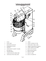
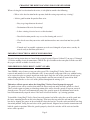
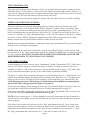
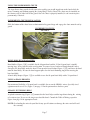
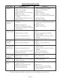
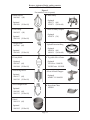
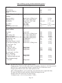
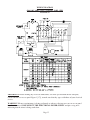
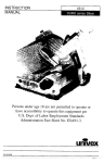
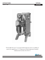
OPERATORS
MANUAL
SRM60+
MIXER
Persons under the age of 18 are not permitted to operate or have accessibility to
operate this equipment per U.S. Department of Labor Employment Standards
Administration Fact Sheet No. ESA91-3.
SRM60+/0109
0011066
ED2
Welcome to Univex
Thank you for purchasing this Univex Product.
Your new SRM60+ mixer has been designed with advanced performance and safety features that make it an
excellent addition to your food preparation equipment. Like all Univex mixers, slicers, meat grinders and
accessories, this mixer is engineered to provide years of reliable service.
If you have any questions concerning the operation of this unit, or if we can be of further assistance, please
call our Customer Service Department for the location of your nearest service representative.
Univex Customer Service:
USA & Canada 800-256-6358
International 603-893-6191
Or visit us on-line at www.univexcorp.com under service agents.
Safety is our top priority
READ AND MAKE SURE THAT YOU UNDERSTAND THE INSTRUCTIONS AND SAFETY
WARNINGS IN THIS BOOKLET BEFORE ATTEMPTING TO OPERATE THIS MIXER OR
ATTACHMENTS.
NEVER PUT FINGERS OR HANDS IN THE BOWL WHILE THE MIXER IS OPERATING OR
SERIOUS INJURY COULD RESULT.
NEVER ATTEMPT TO CLEAR A JAMMED ATTACHMENT OR STALLED MIXER WITHOUT
SHUTTING THE POWER OFF AND DISCONNECTING THE ELECTRICAL POWER SUPPLY.
ALWAYS REPLACE THE POWER TAKE-OFF (PTO) CAP WHEN ATTACHMENTS ARE NOT IN
USE.
DO NOT OPERATE THIS MIXER WITHOUT THE BOWL IN PLACE.
DO NOT OPERATE THIS MIXER WITHOUT THE SWING RING™ SAFETY GUARDS IN PLACE.
Page 1
TABLE OF CONTENTS
DESCRIPTION
PAGE
TABLE OF CONTENTS . . . . . . . . . . . . . . . . . . . . . . . . . . . . . . . . . . . . . . . . . . . . . . . . . . . . . . . . . . .2
LIST OF ILLUSTRATIONS . . . . . . . . . . . . . . . . . . . . . . . . . . . . . . . . . . . . . . . . . . . . . . . . . . . . . . . .2
CHOOSING THE RIGHT LOCATION FOR YOUR MIXER . . . . . . . . . . . . . . . . . . . . . . . . . . . . . .4
USER FRIENDLY SWING RING™ SAFETY GUARD . . . . . . . . . . . . . . . . . . . . . . . . . . . . . . . .4-5
OPERATING THE SRM60+ MIXER . . . . . . . . . . . . . . . . . . . . . . . . . . . . . . . . . . . . . . . . . . . . . . . . .5
SECURING THE BOWL AND INSTALLING THE AGITATOR . . . . . . . . . . . . . . . . . . . . . . . .5
USING THE BOWL LIFT . . . . . . . . . . . . . . . . . . . . . . . . . . . . . . . . . . . . . . . . . . . . . . . . . . . . . . .6
TIMER AND START/STOP CONTROLS . . . . . . . . . . . . . . . . . . . . . . . . . . . . . . . . . . . . . . . . . . .6
VARI-SPEED CONTROL . . . . . . . . . . . . . . . . . . . . . . . . . . . . . . . . . . . . . . . . . . . . . . . . . . . . . . .6
USING THE INGREDIENTS CHUTE . . . . . . . . . . . . . . . . . . . . . . . . . . . . . . . . . . . . . . . . . . . . .7
BOWL DOLLIES AND ADAPTER . . . . . . . . . . . . . . . . . . . . . . . . . . . . . . . . . . . . . . . . . . . . . . . .7
USING A SMALLER BOWL . . . . . . . . . . . . . . . . . . . . . . . . . . . . . . . . . . . . . . . . . . . . . . . . . . . .7
SPLASH EXTENSION RING . . . . . . . . . . . . . . . . . . . . . . . . . . . . . . . . . . . . . . . . . . . . . . . . . . . .7
USING THE POWER TAKE-OFF (PTO) . . . . . . . . . . . . . . . . . . . . . . . . . . . . . . . . . . . . . . . . . . . . . .8
CLEANING YOUR MIXER . . . . . . . . . . . . . . . . . . . . . . . . . . . . . . . . . . . . . . . . . . . . . . . . . . . . . . . .9
OPERATOR’S PREVENTIVE MAINTENANCE . . . . . . . . . . . . . . . . . . . . . . . . . . . . . . . . . . . . . . .9
TROUBLE SHOOTING GUIDE . . . . . . . . . . . . . . . . . . . . . . . . . . . . . . . . . . . . . . . . . . . . . . . . . . . .10
WARRANTY . . . . . . . . . . . . . . . . . . . . . . . . . . . . . . . . . . . . . . . . . . . . . . . . . . . . . . . .BACK COVER
LIST OF ILLUSTRATIONS
ILLUSTRATION
FIGURE
FIGURE
FIGURE
FIGURE
FIGURE
FIGURE
1
2
3
4
5A
5B
OVERALL VIEW OF THE SRM60+ MIXER .............................................................3
INGREDIENTS CHUTE...............................................................................................7
BEATERS, AGITATORS, BOWLS, & ACCESSORIES ............................................11
TABLE OF MIXING CAPACITIES & RECOMMENDED AGITATORS ................12
WIRING DIAGRAM 208-240V, 60HZ, 1PH / 220-240V, 50HZ, 1PH ....................13
WIRING DIAGRAM 208-240V, 60HZ, 3PH / 220V, 50HZ, 3PH
200V, 50/60HZ, 3PH...............................................................14
FIGURE 5C WIRING DIAGRAM 460V, 60HZ, 3PH / 380V, 50HZ, 3PH...................................15
Page 2
OVERALL VIEW OF FOOD MIXER
FIGURE 1
1.
2.
3.
4.
5.
6.
7.
8.
9.
10.
BOWL
BOWL RING
BEATER HEAD SHAFT
INGREDIENT CHUTE
MAGNET
SWING RING™ SAFETY GUARD
PTO HUB #12
THUMB SCREW
LOWER MOUNTING BRACKET
UPPER MOUNTING BRACKET
11.
12.
13.
14.
15.
16.
17.
18.
19.
20.
Page 3
TIMER
SPEED CONTROL LEVER
SPEED INDICATOR LABEL
START PUSH-BUTTON (GREEN)
STOP PUSH-BUTTON (RED)
BOWL LIFT HANDLE
REAR ACCESS PANEL
BOWL SUPPORT
BOWL CLAMP
BOWL SUPPORT PIN
CHOOSING THE RIGHT LOCATION FOR YOUR NEW MIXER
When selecting the best location for the mixer, it is helpful to consider the following:
• Where is the best location for the operator, both for saving steps and easy viewing?
• Is this a good location for product flow as in:
• Easy to get ingredients to the mixer?
• Destination of the mix after mixing?
• Is there existing electrical service at this location?
• Does this location provide easy access for cleaning and service?
• Check to be sure that your mixer with attachments does not extend out into heavy traffic
areas.
• If stands and / or portable equipment are to be used alongside of your mixer, can they be
moved easily to and from your mixer?
IMPORTANT ELECTRICAL SERVICE INFORMATION
Electrical wiring instructions are found in the wiring diagrams (Figures 5A thru 5C) on pages 13 through
15. Before making electrical connections, CHECK the specifications on the nameplate to make sure that
they agree with the available electrical service.
USER FRIENDLY SWING RING™ SAFETY GUARD
Your SRM60+ mixer features a two part safety guard. The Swing Ring™ Safety Guard is easily
removed and installed, as well as dishwasher safe. It conveniently swings out of the way without having
to be removed to place or sample ingredients in the bowl. Only one side of the guard needs to be open
when adding ingredients. This two-piece design handles and fits conveniently in your sink or dishwasher. It also provides a clear view of the product throughout the mixing cycle.
This mixer will not operate unless the Swing Ring™ Safety Guard is properly engaged.
The guards activate safety switches that enable the mixer to operate only when the guards are closed.
These switches protect against accidental operation of the mixer when the guards are open or removed
from the mixer. The mixer will automatically stop if the guard is opened. An additional switch in the
bowl lift automatically stops the mixer if the bowl is lowered from the “up” (mixing) position.
To install the Swing Ring™ Safety Guard, insert the pointed end of the rod at the rear of the guard into
the lower mounting bracket on the mixer housing. Then insert the top end of the rod into the upper
bracket by aligning the groove in the rod with the slot in the bracket. Press the rod in and allow it to drop
down into position. Swing the two halves of the guard forward. Magnets located on the transmission will
hold the guards in position. When the guard is properly closed, the switches will be activated and the
mixer can be operated.
Page 4
To remove the guard, simply reverse the installation procedure. Grip the two halves of the guard and
pull it open. Use an upward motion to release each half of the guard from the bracket.
To open the guard for access to the bowl, first turn the mixer off by pushing the red “Stop” pushbutton (Figure 1 [15]). Pull open the two halves of the guard and swing one or both guards outward. It is
not necessary to remove them. Close the guards and press the green “Start” push-button (Figure 1[14])
to resume mixing operations.
OPERATING THE SRM60+ MIXER
Your Univex SRM60+ mixer is designed to meet the cook’s and baker’s demand for an efficient,
dependable appliance. It should give unfailing performance over a period of years when operated and
maintained according to the instructions contained herein.
The mixer drives various agitator attachments through a beater head shaft to beat, mix, or whip liquid,
viscous, or dry ingredients. The shaft is driven by a sturdy motor whose power is transmitted by a
rugged, cogged belt and a continuously variable transmission (CVT) through a gear train and a planetary
gear set. The speed of the beater shaft can be varied from approximately 75 to340 revolutions per minute
(RPM). (See Figure 3 on page 11 for part numbers of various agitators, attachments and accessories.)
The SRM60+ mixer is equipped with a power take-off (PTO) that operates other attachments such as
slicers, graters and grinders. The PTO speed can be varied from 85 to 395 rpm. Be sure to read and
follow all safety instructions provided by the manufacturers of attachments that you operate on
the PTO. The PTO hub should be covered with the PTO cap provided with your mixer when not in use
to prevent accidental insertion of fingers into the PTO housing during operation.
Warning: Never put hands, spoons, utensils or other objects into the bowl while the mixer is
operating!
Note: Noise emissions for this mixer are below 70db (A).
SECURING THE BOWL AND INSTALLING THE MIXER AGITATOR
Place the bowl on the bowl support (Figure 1 [18]). The indentation on the bowl ring must align with the
pin at the rear of the bowl support. Align the holes in the bowl rim with the pins on the bowl support and
lower the bowl into position. Secure the bowl in place by turning the bowl clamps (Figure 1 [19]).
With the bowl in the “down” position, install the desired agitator by sliding it upward on the beater head
shaft (Figure 1[3]). Rotate the agitator counter-clockwise until it is engaged.
Note: Serious injury may result if the bowl is not positioned properly on the bowl support using the
bowl support pins and firmly closing the clamps.
With the bowl secured, add ingredients. Liquids should be added first. The bowl is now ready to be
raised to the “up”(mixing) Position by turning the bowl lift handle (Figure 1 [16]) clockwise.
Note: Exceeding the mixer capacity, (Figure 4) on page 12, can cause damage to the mixer and will void
the factory warranty.
When using the wire whip agitator, raise the bowl to the “up” position first and then add ingredients to
avoid wire whip damage.
Close and secure the Swing Ring™ Safety Guard before proceeding.
Page 5
USING THE BOWL LIFT
The mixer will not operate unless the bowl is in the “up” position. Raise the bowl by turning the bowl
lift handle (Figure 1 [16]) clockwise. To lower the bowl, turn the bowl lift handle counter-clockwise. If
your mixer is equipped with the power lift option (instead of the handle), turn the power bowl lift switch
clockwise to raise the bowl and counter-clockwise to lower the bowl.
It is necessary to lower the bowl to change the agitator. This also makes the bowl accessible for filling.
TIMER AND START/STOP CONTROLS
This mixer will start only when the Swing Ring™ Safety Guard is closed, the bowl is in the raised
position and the timer is set or placed in the “HOLD” position. To start the mixer, first turn the timer
(Figure 1 [11]) to the desired mixing time then push the Green “Start” push-button (Figure 1 [14]). The
mixer will automatically stop when the timer has reached “0”. To stop the mixer before the timer has
reached “0”, push the red “Stop” push-button (Figure 1 [15]). The timer may be set for up to 15 minutes
or may be set to the “HOLD” position for continuous operation. When setting a time of less than 5
minutes, turn the timer beyond 5 minutes and then return it to the desired time.
Both the Start and Stop push-buttons are momentary contact type push-buttons. They prevent accidental
start-up in the event of power interruption.
NOTE: Although the motor shuts off instantly when the Swing Ring™ Safety Guard is opened, or the
bowl is lowered, or the “Stop” push-button is pushed, the agitator may NOT come to a complete stop for
several revolutions. DO NOT PUT HANDS OR UTENSILS INTO THE BOWL OR NEAR THE
BEATER HEAD SHAFT UNTIL IT HAS FULLY STOPPED.
VARI-SPEED CONTROL
A major advantage of Univex mixers is there Continuously Variable Transmission (CVT). Unlike other
mixers, CVT lets you change speeds while the mixer is running. To change speeds move the speed
control lever (Figure 1 [12]) to the desired speed. The speed indicator label (Figure 1 [13]) shows four
speeds. Numerous intermediate speeds give the cook or baker tremendous flexibility.
Use speed “1” (slow) for heavy mixtures like pizza, bread or roll dough. Speed “1” should also be used
with the meat and food chopper attachment. For most mixing tasks, start on speed “1” and progress to
higher speeds as needed. Use high speeds for whipping cream and beating eggs, and thin batter. To
avoid damaging your mixer, follow the speed, volume limits and attachments recommendations
shown in the table of mixing capacities (Figure 4) on page 12.
If you notice any slippage during mixing, the mixer may be overloaded. Reduce the load, or reduce the
speed until the mixing action is smooth. Refer to the Trouble-Shooting Guide on page 10.
If the mixer jams and the motor stalls, immediately press the “Stop” push-button. Take necessary steps
to reduce the load. Never put hands in the bowl to clear a jam.
NOTE: Always return to speed “1” before shutting the mixer off. Do not move the speed control lever
when the mixer is not running, because this will cause the belt to become loose and the mixer will not
operate properly.
If the mixer has been shut off by the timer, or the “Stop” push-button in speed 2, 3 or 4, follow these
steps to avoid belt slippage or jerky start: Empty the bowl. Set the timer to “HOLD”. Press the “Start”
push-button and as the mixer begins to operate, move the speed control lever back to speed “1”. Press
the “Stop” push-button and return the timer to “0”. Your mixer is now ready for use.
Page 6
USING THE INGREDIENTS CHUTE
The ingredients chute provided with your mixer enables you to add ingredients to the bowl while the
mixer is running and without opening the Swing Ring™ Safety Guard. The chute may be installed on
the front or side of either half of the guard. Once the chute is properly installed, it can remain in place
permanently, if desired.
INGREDIENTS CHUTE INSTALLATION
Slide the bottom of the chute between horizontal safety guard rings and engage the chute onto the safety
guard.
INGREDIENTS CHUTE
FIGURE 2
BOWL DOLLIES AND ADAPTER
Bowl dollies (Figure 3 [H]), available for the 60 quart bowl and the 30 for 60 quart bowl, simplify
moving large, heavy batches to the next location. To remove heavy batches of dough from the mixer,
first place the bowl dolly under the bowl. Then open the bowl clamps (Figure 1 [19]) and lower the bowl
onto the bowl dolly. Be sure the bowl support pins clear the bowl mounting ring before moving the
bowl and dolly.
A bowl dolly adapter (Figure 3 [I]) is available to use the 60 quart bowl dolly with a 30 quart bowl.
USING A SMALLER BOWL
For maximum flexibility, a 30 quart bowl is available for use on the SRM60+ mixer. Specially sized
agitators must be used. See (Figure 3) on page 11 for the part numbers for these parts.
SPLASH / EXTENSION RING
A splash/extension ring (Figure 3 [J]) mounted to the bowl helps confine ingredients during the mixing
of certain recipes. Never use the ring to overload the bowl. Consult the Table of Mixing capacities
Figure 4 on page 12 for appropriate loads.
NOTE: Overloading the mixer beyond the factory specifications can damage the mixer and will void
the warranty.
Page 7
USING THE POWER TAKE-OFF (PTO)
The Power Take-Off (PTO) hub (Figure 1 [7]) accommodates #12 tapered attachments such as a
vegetable slicer and shredder, or a meat and food chopper. The mixers speed control lever also controls
the PTO drive speed.
Before installing attachments, turn the mixer off and disconnect the electrical power supply. Remove the
PTO cap and loosen the thumb screw (Figure 1 [8]) on the PTO hub. Insert the attachment with a slight
twist until it is firmly in place. Tighten the thumb screw. Be sure to read and follow all safety
instructions provided for the attachments that you operate on the PTO.
SAFETY NOTES:
When grinding meat, chopper attachments must never run faster than speed “1”.
For vegetables, attachments may run at a higher speed.
Always turn the mixer off and disconnect the electrical power supply to install or remove the
attachment.
Always return to speed “1” before shutting the mixer off.
Cover the PTO hub with the PTO cap when the PTO is not in use.
CLEANING YOUR MIXER
Consistent use of the following procedures will ensure that your mixer is in optimum operating
condition.
• Warning: disconnect the electrical power supply before cleaning.
• Wash the body of the mixer, the bowl support, and the beater shaft with warm water and mild soap.
• Avoid excess water in the area of the safety switches that protrude from the housing where the
Swing Ring™ Safety Guard is mounted.
• Do not rinse the mixer with a hose.
• Do not use abrasive pads to wash the mixer.
• Dry the mixer thoroughly with a soft cloth.
• Wash the bowl and beater immediately after use. If an egg mixture or flour batter have been used,
rinse the bowl and beater with cold water before washing with hot water. Wash the Swing Ring™
Safety Guard in the same manner, or in a dishwasher.
• Dry bowls and beaters and the Swing Ring™ Safety Guard thoroughly.
OPERATOR’S PREVENTIVE MAINTENANCE
For best long-term performance, operators should follow these simple practices:
• Lightly lubricate the beater shaft (Figure 1 [3]) after washing with a food grade lubricant.
• Do not cover the mixer with a plastic bag, as this traps humidity inside the mixer.
• Do not overload the mixer. Overloading is the #1 cause of mixer failure. Follow the Table of
Mixing Capacities Figure 4 on page 12. It may be helpful to post a copy of this table adjacent to
the mixer.
• Keep the mixer properly lubricated. Lack of lubrication is the #2 cause of mixer failure. Key
mixer components require lubrication after each 500 hour of operation.
• Only change speeds with the mixer running. Changing speeds with the mixer off will cause the
belts to loosen, and the mixer will not turn (see the Trouble-Shooting Guide on page 10). Return
to speed “1” before shutting the mixer off. Use the procedure described on page 6 to return the
mixer to speed “1” if the mixer is shut off in a higher speed.
Page 9
TROUBLE-SHOOTING GUIDE
TROUBLE
1. Mixer will not
operate
2. Mixer runs but
agitator will
not turn.
3. Agitator stalls
during mixing
POSSIBLE CAUSE
1.1 Electrical service down.
1.2 Burned switch contacts.
1.3 Timer not turned on.
1.4 Motor capacitor defective (1PH only)
1.5 Burned out motor.
1.6 Magnetic starter tripped due to
overload.
1.7 Safety Ring not mounted and closed.
1.8 Bowl not raised.
2.1 Shifting speed with the mixer not
running.
2.2 Broken or slipping belt.
2.3 Key or pin sheared on input shaft,
input gear, bevel pinion, vertical shaft
or beater shaft
3.1 Loose belt.
REMEDY
1.1 Check electrical service. Replace fuse or
reset circuit breaker as necessary.
1.2 Replace or clean contacts. *
1.3 Turn timer on.
1.4 Replace capacitor. *
1.5 Remove, test, repair or replace. *
1.6 Wait several minutes and push start button.
1.7 Install Safety Ring.
1.8 Raise bowl completely.
2.1 With mixer running, slowly move speed
control lever forward then backward to reengage belt.
2.2 Tighten or replace. *
2.3 Notify a service agent.
3.1 Readjust pulley center distance to tighten
belt. *
3.2 Mixer bowl is over-loaded.
3.2 Adjust contents of bowl per Mixing
Capacities Table.
3.3 Shift speed lower till beater head rotates
3.3 Speed set too high for the mix.
smoothly.
3.4 Clean pulleys and replace belt. *
3.4 Contamination of belt with grease.
4. Speeds will
4.1 Loose belt.
4.1 Readjust pulley center distance to tighten
not change
belt. *
properly.
4.2 Vari-speed pulley inoperable.
4.2 Remove, clean and lubricate or
replace.*
5. Mixer runs but 5.1 Mixer bowl is over-loaded.
5.1 Adjust contents of bowl per Mixing
repeatedly cuts
Capacities Table.
out and stops
5.2 Speed set too high for the mix.
5.2 Shift speed lower till beater head rotates
smoothly.
5.3 Service voltage too low or fluctuating. 5.3 Check electrical voltage.*
5.4 Starter improperly set.
5.4 Adjust amp setting on starter.*
6. Attachments
contact bottom
of bowl.
7. Attachments
contact side of
bowl.
8. Excessive
noise.
6.1 Dented bowl.
6.2 Bowl height is set too high.
6.1 Remove dent or replace bowl.
6.2 Reset bowl height. *
7.1 Dented bowl.
7.2 Insufficient clearance between bottom
of bowl and beater.
6.1 Gears need to be repacked with grease
or oil level is low.
6.2 Badly worn or frayed drive belts.
6.3 Attachments hitting bowl.
6.4 Overloaded mixing bowl.
7.1 Remove dent or replace bowl.
7.2 Adjust bowl height. *
6.1 Notify a service agent.
6.2 Replace belt. *
6.3 Inspect for cause in items 5 above.
6.4 Adjust contents of bowl per Mixing
Capacities Table.
* Remedies designated with an * require the service of an authorized service agent.
Page 10
Beaters, Agitators, Bowls, and Accessories
Available for the SRM60+ Mixer
Figure 3
Part numbers (size in quarts)
A. Batter Beater
1061083 (60)
H. Bowl Dolly
Optional
1061971 (60)
1030971 (30 for 60)
Optional
1061096 (30 for 60)
B. Wire Whip
1061095 (60)
I. 30 for 60 Dolly Adapter
Optional
1030972 (30)
Optional
1061182 (30 for 60)
C. Dough Hook
1061089 (60)
J. Splash/Extension Ring
Optional
1061298 (60)
1061299 (30 for 60)
Optional
1061090 (30 for 60)
D. Pastry Knife
K. Vegetable Slicer/Grater
Optional
1061087 (60)
1061088 (30 for 60)
E. Four-Wing Beater
Optional
VS9 Slicer 1000950
VS9H Grater 1001050
L. Meat & Food Chopper
Optional
1061197 (60)
1061301 (30 for 60)
F. sweet Dough Beater
Optional
1061229 (60)
1061313 (30 for 60)
Optional
ALMFC12 1000550
M. Ingredient Chute
1000541
G. Bowl
1061192 (60)
Optional
1061105 (30 for 60)
Page 11
Table of Mixing capacity and Recommended Agitators
Figure 4
MODEL
SRM 60+
Bowl capacity
Attachment Hub Size
Motor
72 qt.
#12
3 Hp
68.1 L
40 lb.
12 qt.
18 qt. (oil)
18.2 kg.
11.4 L.
17 L. (oil)
Kitchen Capacities (single
batches)
Agitator
Mashed potatoes
Whipping cream
Mayonnaise
Batter beater, 4-Wing beater
Wire whip, 4-Wing beater
Batter beater, Wire whip,
4-Wing beater
Wire whip
Wire whip
Batter beater
Egg whites
Meringue
Waffle or pancake batter
Bakery Capacities
(single batches)
Agitator
Pie dough
Cake
Short sponge cake
Sponge cake batter
Angle food batter (8-10 oz. cake)
Marshmallow icing
Fondant icing
Shortening & sugar creamed
Egg & sugar for sponge cake
Pastry knife
Batter beater, 4-Wing beater
Wire whip, 4-Wing beater
Wire whip, 4-Wing beater
Wire whip, 4-Wing beater
4-Wing beater
Batter beater
Batter beater
Batter beater, 4-Wing beater
Use only speed 1 for:
Pizza dough
Thin, 40% AR
Medium, 50% AR
Thick, 60% AR
Dough hook
Dough hook
Dough hook
Use only speed 1 or 2 for:
Bread / roll dough
Heavy, 55% AR
Light to medium 60%AR
Dough hook
Dough hook
Raised doughnut dough
65% AR
Dough hook
2 qt.
1.9 L.
1-1/2 qt.(water) 1.4 L. (water)
24 qt.
22.7 L.
50 lb.
50 lb.
45 lb.
36 lb.
45 cakes
5 lb.
36 lb.
48 lb.
24 lb.
22.7 kg.
22.7 kg.
20.5 kg.
16.4 kg.
45 cakes
2.3 kg.
16.4kg.
21.8 kg.
10.9 kg.
40 lb.
75 lb.
80 lb.
18.2 kg.
34.1 kg.
36.4 kg.
80 lb.
80 lb.
36.4 kg.
36.4 kg.
50 lb.
22.8 kg.
NOTES: Recommended speeds are for the capacities listed.
Dough capacity, for bread, rolls, pizza, bagels or doughnut, is based on a 12% flour moisture
and 70˚F (21˚C) water temperature. Reduce capacity by 10% if cold water is used.
If higher gluten flour is used, reduce total capacity by 10%.
AR% (Absorption Ratio) = the weight of the water divided by the weight of the flour.
The lower the AR% the stiffer and more difficult the dough is to mix.
An AR% below 40% will reduce the total capacity.
1 Gallon of water = 8.3 lb. (1 liter of water = 2.2lb.)
Page 12
WIRING DIAGRAM
(208-240V, 60HZ, 1PH) (220-240V, 50HZ, 1PH)
FIGURE 5A
IMPORTANT: Before making any electrical connections, check the specifications on the data plate,
(located on the rear access panel Figure 1 [17]), to make sure that they agree with those of your electrical
service.
WARNING: Whenever maintenance is being performed, or whenever the top cover or rear access panel
have been removed, DISCONNECT THE ELECTRICAL POWER SUPPLY and place a tag on it
indicating that the mixer is being worked on.
Page 13
WIRING DIAGRAM
(208-240V, 60HZ, 3PH) (220V, 50HZ, 3PH) (200V, 50/60HZ, 3PH)
FIGURE 5B
IMPORTANT: Before making any electrical connections, check the specifications on the data plate,
(located on the rear access panel Figure 1 [17]), to make sure that they agree with those of your electrical
service.
WARNING: Whenever maintenance is being performed, or whenever the top cover or rear access panel
have been removed, DISCONNECT THE ELECTRICAL POWER SUPPLY and place a tag on it
indicating that the mixer is being worked on.
Page 14
WIRING DIAGRAM
(460V, 60HZ, 3PH) (380V, 50HZ, 3PH)
FIGURE 5C
IMPORTANT: Before making any electrical connections, check the specifications on the data plate,
(located on the rear access panel Figure 1 [17]), to make sure that they agree with those of your electrical
service.
WARNING: Whenever maintenance is being performed, or whenever the top cover or rear access panel
have been removed, DISCONNECT THE ELECTRICAL POWER SUPPLY and place a tag on it
indicating that the mixer is being worked on.
Page 15
Warranty
The Univex SRM60+ mixer carries a two-Year, on-site, parts and
labor warranty against any defects in materials or workmanship. The
two-year period begins on the date of purchase by the end user and
remains in full effect provided the unit is used properly in accordance
with our instructions. Any Work to be performed under this warranty
must be performed between the hours of 8:00 a.m. and 5:00 p.m. local
time, Monday through Friday. Univex will not cover overtime charges
of any kind. Please call the Univex Warranty Service Department at
(800) 258-6358 to report any warranty claims before arranging repair
or attempting to return the unit to Univex Corporation.
Damages incurred in transit or incurred because of installation error,
accident, alteration or misuse are not covered. Transit damages should
be reported to the carrier immediately.
Univex will not be liable for any consequential, compensatory,
incidental or special damages.
3 Old Rockingham Road, Salem, N.H. 03079-2140 Telephone -603-893-6191
TOLL FREE ORDERING FAX 1-800-356-5614
Fax 1-603-893-1249