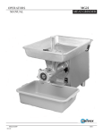
1
Qpi vex
Exacting
Exacting Standards,
Standa rds, Just
Just Like
Li ke Yours,
Y ou rs, since
since 1948
1948
S
RM60/SRM80
SRM6O/SRM8O
SRM60/SRM80
S
wing Ring
Ring Series
Series
Swing
S
RM60/SRM80 PPLANETARY
LANETARY M
IXERS
SRM6O/SRM8O
MIXERS
Maintenance & Parts Manual
Persons under the age of 18 are not permitted to operate or have
have
accessibility to operate this equipment per U.S. Dept. of Labor Employment
Standards Administration Fact Sheet No. ESA91-3.
UNIVEX CORPORATION - 3 Old Rockingham
Rockingham Road
Road - -Salem,
Salem,NH
NH03079-2140
03079-2140- –Tel
Tel(800)
(800)258-6358
258-6358-–Fax
Fax(800)356-5614
(800) 356-5614
Int'l
Int’lTel
Tel603-893-6191
603-893-6191 -–Int'l
Int’lFax
Fax603-893-1249
603-893-1249- –Website
Websitewww.univexcorp.com
www.univexcorp.com - E-mail
E-mail [email protected]
[email protected]
Printed in USA
PDF compression, OCR, web optimization using a watermarked evaluation copy of CVISION PDFCompressor
SRM6O+/SRMSO+
Welcome to Univex
Thank you for purchasing this Univex product.
Your new SRÌvI6O+/SRÌvI8O+ Mixer has been designed with advanced
performance and safetyfeatures that make it an excellent addition to your
foodpreparation equipment. Like all Univex mixers, slicers, meat grinders
and accessories, this mixer is engineered to provide years ofreliable service.
If you have any questions concerning the operation ofthis unit, or ifwe can be
offurther assistance, please call our Customer Service Department.
Univex Customer Service:
USA & Canada 8OO256-6358
International 603-893-6191
Safety is our Top Priority
READ AND MAKE SURE THAT YOU UNDERSTAND THE
INSTRUCTIONS AND SAFETY WARNINGS IN THIS BOOKLET BEFORE
ATTEMPTING TO OPERATE THE MIXER OR ATTACHMENTS.
NEVER PUT FINGERS OR HANDS IN THE BOWL WHILE THE MIXER IS
OPERATING OR SERIOUS INJURY COULD RESULT.
NEVER ATTEMPT TO CLEAR A JAMMED ATTACHMENT OR
STALLED MIXER WITHOUT SHUTTING THE POWER OFF.
DISCONNECT THE ELECTRICAL PLUG FROM ELECTRICAL OUTLET.
ALWAYS REPLACE THE POWER TAKE-OFF (PTO) CAP WHEN
ATTACHMENTS ARE NOT IN USE.
DO NOT OPERATE THIS MIXER WITHOUT THE COWL IN PLACE
WARRANTY
The Univex SRM6O+ISRM8O+ Mixer is warranted by Univex Corporation against defects in materials
ançl workmanship for a period of one year from date of delivery ifdelivered to a destinatìon in the
United States or Canada.
Contact Univex Customer Service to report any warranty claim. Univex shall not be liable for any
consequential, compensatory, incidental, or specìal damages. damages incurred in transit or from
installation error, accident, alteration, or misuse are not covered. Transit damages should be reported to
the carrier immediately.
Ifthe SRM6O+/SRMSO+ Mixer is deliveredto a country otherthenthe United States or Canada, it is
warranted by Univex's authorized distributor. Contact your distributor directly to report any warranty
claims outside ofthe United States or Canada.
Page 1
PDF compression, OCR, web optimization using a watermarked evaluation copy of CVISION PDFCompressor
SRM6O+/SRM8O+
TABLE OF CONTENTS
PAGE
DESCRIPTION
WARRANTY
TABLE OF CONTENTS, LIST OF ILLUSTRATIONS
CHOOSING THE RIGHT LOCATION FOR YOUR NEW MIXER
USER-FRIENDLY SWING RING'TM SAFETY GUARD
OPERATING THE SRM6O+ISRM8O+ MIXER
USING THE POWER TAKE-OFF (PTO)
TABLE OF MIXING CAPACITIES & RECOMMENDED AGITATOR SRM6O+
TABLE OF MIXING CAPACITIES & RECOMMENDED AGITATOR SRM8O+
BEATERS, AGITATORS, BOWLS, & ACCESSORIES SRM6O+
BEATERS, AGITATORS, BOWLS, & ACCESSORIES SRMSO+
CLEANING YOUR MIXER
OPERATOR'S PREVENTIVE MAINTENANCE
TROUBLE SHOOTING GUIDE
REMOVAL OF TOP COVER
MECHANICS MAINTENANCE
REPAIR INSTRUCTIONS
REPLACEMENT PARTS, LISTS
ELECTRICAL CONNECTION AND ROTATION
WIRING DIAGRAMS
i
2
3
3 -4
4-6
6-7
8
9
10
11
13
13
14 - 15
16
16 - 18
19 -24
25 - 37
39
40 -42
LIST OF ILLUSTRATIONS
ILLUSTRATION
PAGE
OVERALL VIEW OF MIXER
FIGURE 2 LUBRICATION INSTRUCTIONS
GEAR BOX TRANSMISSION
FIGURE 3
FIGURE 4 BEATER HEAD & VERTICAL SHAFT ASSEMBLY
POWER TAKE OFF ASSEMBLY
FIGURE 5
FIGURE 6 INPUT ASSEMBLY
FIGURE 7 BOWL LIFT ASSEMBLY
SPEED CONTROL ASSEMBLY
FIGURE 8
FIGURE 9 BOWL SUPPORT ASSEMBLY
FIGURE 10 HOUSING ASSEMBLY
DRIVE ASSEMBLY
FIGURE 11
FIGURE 12A WIRING DIAGRAM 208-240V, 60HZ, 1PH,
220-240V, 50HZ, 1PH
FIGURE
12
18
1
FIGURE l2B WIRING DIAGRAM 208-240V, 60HZ. 3PH, 220V, 50HZ, 3PH
200V, 50/60HZ, 3HP
FIGURE 12C WIRING DIAGRAM 460V, 60HZ, 3PH, 380V, 50HZ, 3PH
25
26
27 -28
29
30 -31
32 -33
34
35 - 36
37 - 38
40
.., .
41
42
Page 2
PDF compression, OCR, web optimization using a watermarked evaluation copy of CVISION PDFCompressor
SRM6O+/SRMSO+
CHOOSING THE RIGHT LOCATION FOR YOUR NEW MIXER
When selecting the best location for the mixer, it is helpful to consider the following:
. Where is the best location for the operator, both for saving steps and easy
viewing?
s
Is this a good location for product flow as in:
*
Easyto get ingredients to the mixer?
s
Destination ofthe mix alter mixing?
. Is there existing electrical service at this location?
. Does this location provide easy access for cleaning and service?
. Check to be sure that your mixer with attachments does not extend out
into heavy traffic areas.
. Ifstands and/or portable equipment are used along side ofyour mixer,
can they be moved easily to and from your mixer?
. Ifunit is not provided with a plug, then the unit is to be fitted with a primary disconnect
device that has a contact separation of at least 3mm in all poles.
IMPORTANT ELECTRICAL SERVICE INFORMATION
Electrical wiring instructions are found in the wiring diagram (Figures l2Athru 12C). Before making
electrical connections, CHECK the specifications on the nameplate to make sure that they agree with
those on your electric service.
USER-FRIENDLY SWING RINGTMSAFETY GUARD
Your SRM6O+/SRMSO+ Mixer features a newly updated, 2-part safety guard. The Swing RingTM
Safety Guard ring is easily be removed and installed, as well as dishwasher safe. It conveniently swings
out ofthe way without having to be removed to place or sample ingredients in the bowl. Only one side
ofthe guard needs to be open when adding ingredients. You'llfindthis twopiece design is easy to
handle and fits conveniently in your sink or dishwasher. It also provides a clear view ofthe product
throughoutthe mixing cycle.
This mixerwifi not operate unless the Swing Ring1M Safety Guard Is properly engaged.
Metal tabs atthe rear ofthe guard activate twin switches that enable the mixer to run only when the
guard is securely closed. These switches protect against accidental operation ofthe mixer when the
safety guard is open or removed from the mixer. The mixer wìll automatically stop ifthe guard is open.
Additional switches in the bowl slide mechanism automatically stop the mixer ifthe bowl is lowered
from the "up" (mixing) position.
To Install the Swing Ring Safety Guard, insert the pointed end ofthe rod at the rear ofthe guard into
the lower mounting bracket on the mixer housing. Then insert the top end ofthe rod into the upper
bracket by aligning the groove in the rod with the slot inthe bracket Press the rod in and allow it to drop
Page 3
PDF compression, OCR, web optimization using a watermarked evaluation copy of CVISION PDFCompressor
SRM6O+/SRM8O+
down into position. Repeat this for each ofthe two sections ofthe guard. Swing the two halves of the
guard forward. When the guard is properly closed, the switches are now activated and the mixer can be
operated.
To remove the guard, simply reverse the installation procedure. Grip the two halves ofthe guard and
pull it open. Use an upward motion to release each halfofthe guard from the bracket on the machine
body.
To open the guard for access to the bow1 first turn the mixer off by pushing the red stop button
(Fig. i [1 2]). Pull open the two halves ofthe guard and swing one or both outward, It is not necessary to
remove them. Close the guard to resume mixing operations.
OPERATING THE SRM3O+ MIXER
Your Univex Mixer is designed to meet the cook's and Baker's demand for an efficient, dependable
appliance. It should give unfailing performance over a period ofyears when operated and maintained
according to the instructions contained herein.
The mixer drives various agitator attachments through a beater head shalt to beat, mix, or whip liquid,
viscous, or dry ingredients. The shaft is driven by a sturdy motor whose power is transmitted by a
rugged, cogged belt and a Continuously Variable Transmission (CVT)through a geartrain and a
planetary gear set. The speed ofthe beater shaft can be varied from approximately 60 to 270 revolution
per minute (rpm)for SRMSO+ and 75 tO 340rpm for SRM6O+. (See page IO & i i for part numbers of
various agitators, attachments and accessories.)
The SRM6O+/SRM8O+ Mixer is equipped with a power take-off(PTO)that operates other attachments
such as slicers, graters and grinders. The PTO speed can be varied from 85 to 385 rpmfor SRMSO+ and
SRM6O+. Be sure to read and follow any safety Instructions provided by the manufacturers of
attachments that you operate on the PTO. The PTO hub should be covered with the PTO cap
provided with your mixer when in use.
Warning--Never put hands, spoons, utensils or other objects into the bowl while the mIxer is
operating!
Note: Noise emissions are below 70db (A).
Securing the Bowl & Installing the Mixer Agitator.
Place the bowl on the bowl support (Fig. i [15]). The indentation on the rim ofthe bowl must align with
the corresponding pin on the mixer housing. Align the holes on eighter side ofthe bowl rim over the pins
on the bowl support andlower the bowl into position. Secure the bowl by turning the bowl clamps (Fig.
i [16]).
With the bowl in the "down" position, installthe desired agitator by sliding it upward onto the beater
shaft (Fig. 1 [1]). Rotate the agitator counter-clockwise until it is engaged.
Safety Note Serious injusy may result ifthe bowl is not fully secured to the bowl support using the bowl
support pins and firmly closingthe clamps.
With the bowl secured, add ingredients. Liquids should be added first. The bowl is now readyto be
raised to the "up"(mixing)position byturningthe bowl lifthandle (Fig. 1[131) clockwise.
When using the wire whip agitator, raise the bowito the "up" position first and then add ingredients to
avoid wire whip damage.
Secure and close the Swing
PgTM Safety Guard before proceeding.
Page 4
PDF compression, OCR, web optimization using a watermarked evaluation copy of CVISION PDFCompressor
SRM6O+/SRM8O+
Using the Bowl Lift
The mixer will not operate unless the bowl is inthe "up " position. Raise the bowl by tuming the bowl
lift handle (Fig. i [13]) clockwise. To lowerthe bowl, turnthe handle counterclockwise.
Ifyour mixer is equipped with the power bowilift option(instead ofthe handle)turn the power bowl lift
switch clockwise to raise the bowl, counter-clockwise to lower the bowl,
It is necessary to lower the bowl to change the agitator. This also makes the bowl accessible for filling
Setting the Tinier - Start/Stop Controls
This mixer will not operate unless the timer has been set to a specified number ofminutes or set in the
"HOLD" position. To startthe mixer, firsiturn the timer dial (Fig. i [81)to the desired mixing time.
Then push the start button(Fig. i [11]). The mixer will automatically stop when the timer reaches "O".
To stop mixing before the timer reaches "O", pushthe red stop button(Fig. i [12]).
The timer may be set for up to 15 minutes ofmixing, or may be set to the "HOLD" position for
continuous operation. When setting a time ofless then 5 minutes, turn the dial beyond 5 minutes and
then return itto the desired time.
Safety Note The mìxer will start only when the Swing RingTMSafety Guard is engaged andthe bowl is
in the raised position. Do not operate the mixer without the bowl in place.
Manual Stop Button
For safety and operational ease, this mixer is equipped with a stop button (Fig.1 [12])that has an
oversized, red mushroom-style cap.
Safety Note Although the motor shuts offinstantly when the Swing RingTM Safety Guard isopened, or
the bowl is lowered, or the stop button is pushed, the agitator may not come to complete rest for several
revolutions. Do not put hands or utensils into bowl or near the beater shaft until it Is stopped.
Both the start button and stop button are momentary contact type. They provide low voltage protection
and prevent accidental start-up in the event ofpower interruption.
Vail-Speed Control
A major advantage ofUnivex mixers is their Continuously Variable Transmission (CVT). Unlike other
mixers, CVT lets you change speed while the mixer Is running. Change speed by movingthe speed
control lever (Fig. 1 [9])to the desiredlevel. The speed indicator (Fig. 1 [10]) shows four speeds.
Numerous intermediate speeds give the Cook or Backer tremendous flexibility.
Use speed 1 (slow) for heavy mixtures like pizza, bread or roll dough. Speed 1 should also be used with
the Meat and Food Chopper attachment For most mixingtasks, start on speed 1 and progress to higher
speeds as needed. Use high speeds for wipping cream, beating eggs, andthin batter. To avoid damaging
your mixer, follow the speed, volume limits and attachments recommendations shown in the
Table ofMixing Capacities on page 8 & 9.
Ifyou notice any slippage during mixing, the mixer may be overloaded. Reduce the load, orreduce
speed until mixing action is smooth. Referto the Trouble- ShootIng Guide on page 14 & 15.
Ifthe mixerjanis and the motor stalls, immediately press the stop button. Take necessary steps to reduce
the load. Never put hands in the bowl to clear siam.
Note Always return to speed i before shutting off the mixer. Do not move the speed control lever
when the mixer is not running, because this will cause belt to become loose and the mixer will not
operate properly.
Page 5
PDF compression, OCR, web optimization using a watermarked evaluation copy of CVISION PDFCompressor
SRM6O+/SRMSO+
If the mixer has been shut off by the timer, or stop button in speed 2, 3 or 4, follow these steps to
avoid belt slippage orjerky start: Empty the bowl. Set the timer to "HOLD". Press the start button.
As the mixer begins to operate, move the speed control lever back to speed i Press the stop button.
Return to "O". Your mixer is now ready for ìts next task.
Using the Ingredients Chute
The ingredients chute provided with your mixer enables you to add ingredients to the bowl while the
mixer is running, and without opening or removing the Swing RingTM Safety Guard. The chute may be
installed on the front or side ofeither halfofthe guard. See below. Once the chute is properly installed,
it can remain in place permanently, if desired.
Ingredients Chute Installation
Slide the bottom ofthe chute between horizontal safety guard rings and engage
the chute onto the safety guard.
Bowl Doffies & Adapter
Dollies (Page 10 & i i [h]), simpliÍj moving large, heavy batches to the next location. To use 40 for SO
bowl or 30 for 60 bowl withthe dolly, you must use a bowl adapter (Page 10 & 11 [i)). To remove
heavy batches from the mixer, first place the dolly underthe bowl. Then open the bowl clamps and
lower the bowl to the dolly. Be sure the bowl support pins clear the bowl mounting brackets before
moving the bowl and dolly.
Using Smaller Bowl
For maximum flexibility, an alternative 30 for 60 quart bowl is available for use on your SRM6O+
Mixer, and a 40 for SO and 60 for 80 for use on your SRM8O+ Mixer. Specially sized agitators must be
used. See page lO & i i for part numbers.
Splash/Extension Ring
A splash/extension ring (page 10 & 11 [j]) mounted to the bowl helps confme ingredients during the
mixing ofcertain recipes. The ring should never be used to overload a mìxer beyond its recommended
capacity. Consultthe Table ofMixing Capacities on page 8 & 9 when you are unsure of appropriate
loads.
USING THE POWER TAKE-OFF (PTO)
The power take-offhub (Fig. 1[5}) accommodates #12 tapered attachments such as a Vegetable Slicer
and Shredder, or a Meat and Food Chopper. The mixer's speed control lever also controls the PTO drive
speed.
Before installing attachments, turn the mixer off. Remove the PTO cap and loosen the thumb screw (Fig.
i [6]) on the PTO hub. Insertthe attachment with a slighttwist until firmly in place. Tighten the thumb
screw. Be sure to read and follow any safety instructions provided for attaclunents that you
operate on the PTO.
Page 6
PDF compression, OCR, web optimization using a watermarked evaluation copy of CVISION PDFCompressor
SRM6O+/SRJ48O+
Safety Notes
When grinding meat, chopper attachments must never run faster then speed 1. For vegetables,
attachments may run at higher speed.
Always turn the mixer off to install or remove attachments.
Always return to speed i before shutting off mixer.
Cover the PTO hub with the PTO cap when not In use.
Page 7
PDF compression, OCR, web optimization using a watermarked evaluation copy of CVISION PDFCompressor
SRM6O+/SpM8o+
SRM6O+ Table ofMixing Capacities & Recommended Agitators
MODEL
SRM6O+
Bowl Capacity
Attachment Hub Size
Motor
72 qt
#12
3 hp
Kitchen Capacities (single
batches)
Agitator(s)
Mashed potatoes
Whipping cream
Mayonnaise
Egg whites
Meringue
Waffle or pancake batter
Bafter beater, 4-wing beater
Wire whip, 4-wing beater
Batter beater, wire whip,
4-wing beater
Wire whip
Wire whip
Batter beater
Bakery Capacities (single
batches)
Agitator(s)
Pie dough
Cake
Short sponge cake
Sponge cake batter
Angle food batter (8-10 oz
cake)
Marshmallow icing
Fondant icing
Shortening & sugar creamed
Egg & sugar for sponge cake
Use only speed i for:
Pizza dough
thin, 40% AR
medium, 50% AR
thick, 60% AR
Use speed i or 2 for:
Bread/roll dough
Heavy, 55% AR
Lìghttomed.60%AR
Raised doughnut dough
65% AR
40 lb
12 qt
18 qt (oil)
2
68. 1 L
18.2 kg
11.4 L
17 L (oil)
11/2 qt(water)
24 qt
1.9 L
1.4 L (water)
22.7 L
Pastry knife
Batter beater, 4-wing beater
Wire whip, 4-wing beater
Wire whip, 4-wing beater
Wire whip, 4-wing beater
50 lb
50 lb
45 lb
36 lb
45 cakes
22.7 kg
22.7 kg
20.5 kg
16.4 kg
45 cakes
4-wing beater
Batter beater
Batter beater
Batter beater, 4-wing beater
5 lb
36 lb
48 lb
24 lb
2.3 kg
16.4 kg
21.8 kg
10.9 kg
Dough hook
Doughhook
Dough hook
40 lb
75 lb
80 lb
18.2 kg
34.1 kg
36.4 kg
Dough hook
Doughhook
80 lb
8Olb
36.4 kg
Dough hook
50 lb
22.8 kg
36.4kg
NOTES: Recommended speeds are for the capacities listed. For larger capacities, reduce
speed. Dough capacity. whether for bread. rolls. nizza. bards or dourhnuts is
based on 12% flour moisture and 70°F (21°C) water temperature. Reduce
capacity if cold water is used. If higher gluten flour is used, reduce total
capacity by 10%.
AR% (Absorption Ratio) = the weight of the water divided by the
weight ofthe flour.
The lower the AR% the stiffer and more difficult the dough is to mix.
AR% below 40% will reduce total capacity.
i gallon of water = 8.3 lb. (1 liter of water 2.21b)
Page 8
PDF compression, OCR, web optimization using a watermarked evaluation copy of CVISION PDFCompressor
SRM6O+/SRM8O
SRMSO+ Table ofMixing Capacities & Recommended Agitators
MODEL
SRM8O+
BowiCapacity
9Oqt
#12
i hp
Attachment Hub Size
Motor
Kitchen Capacities (single
batches)
Agitator(s)
Mashed potatoes
Whipping cream
Mayonnaise
Egg whites
Meringue
Waffle or pancake batter
Batter beater, 4-wing beater
Wire whip, 4-wing beater
Batter beater, wire whip,
4-wing beater
Wire whip
Wire whip
Batter beater
Bakery Capacities (single
batches)
Agitator(s)
Pie dough
Cake
Short sponge cake
Sponge cake batter
Angle food batter (8-10 oz
cake)
Marshmallow icing
Fondant icing
Shortening & sugar creamed
Egg & sugar for sponge cake
85.2 L
50 lb
16 qt
22 qt (oil)
22.7 kg
15.1 L
20.8 L (oìl)
3 qt
2 qt (water)
30 qt
2.8 L
1.9 L (water)
28.4 L
Pastryknife
Batter beater, 4-wing beater
Wire whip, 4-wing beater
Wire whip, 4wing beater
Wire whip, 4-wing beater
60 lb
60 lb
70 lb
54 lb
60 cakes
27.3 kg
27.3 kg
4-wing beater
Batter beater
Batter beater
Batter beater, 4-wing beater
6 1/2 lb
45 lb
55 lb
36 lb
3.0 kg
20.4 kg
25.0 kg
16.4 kg
Doughhook
Dough hook
Dough hook
4Olb
75 lb
80 lb
34. 1 kg
Dough hook
60 lb
27.3 kg
Doughhook
Dough hook
801b
80 lb
36.4 kg
3 1.8 kg
24.5 kg
60cakes
Use only speed i for:
Pizza dough
thin,40%AR
medium, 50% AR
thick, 60% AR
Use speed 1 or 2 for:
Raised doughnut dough
65% AR
Bread/roll dough
heavy,55%AR
lightto med., 60% AR
:
18.2 kg
36.4 kg
36.4kg
Kecommended speeds are for the capacities listed. For larger capacities, reduce
speed. Dough capacity, whether for bread, rolls, pizza, bagels or doughnuts, is
based on 12% flour moisture and 70°F (21°C) water temperature. Reduce
capacity if cold water is used. If higher gluten flour is used, reduce total
capacity by 10%.
AR% (Absorption Ratio) = the weight of the water divided by the
weight of the flour.
The lower the AR% the stiffer and more difficult the dough is to mix,
AR% below 40% will reduce total capacity.
i gallon ofwater = 8.3 lb. (1 liter ofwater = 2.2lb)
Page 9
PDF compression, OCR, web optimization using a watermarked evaluation copy of CVISION PDFCompressor
SRM6O+/SRM8O+
Beaters Agitators Bow1s & Accessories
Available for tile SRM6O+ Mixer
Part numbers (sìze in cuarts
A Batter Beater
1061083
c. Bowl
(60)
Optional
1061096 (3Ofor6O)
B. Wire Whip
1061095
Optional
1061182
(60)
Optional
1061105
(3Ofor6O)
H. Bowl Dolly
(60)
Optional
1061971
1030971
(3Ofor6O)
C. Dough Hook
(60)
(3Ofor6O)
1061098 (60)
30 for 60 Bowl
Dolly Adapter
Optional
1061090 (3Ofcr60)
Optional
1030972
D. Pastxy Knife
I.
J
Optional
1061087 (60)
1061088 (3Ofor6O)
E. Four Wing Beater
Optional
1061197
1061301
F
1061192
Optional
1061298 (60)
1061299 (3Ofor6O)
K. Vegetable Slicer/Grater
Optional
VS9 1000950 Slicer
(60)
(3Ofor6O)
Sweet Dough Beater
Splash/Extension Ring
VS9H 1001050 Grater
L Meat & food Chopper
Optional
1061229 (60)
1061313 (3Ofor6O)
Optional
ALMFC12 1000550
Page 10
PDF compression, OCR, web optimization using a watermarked evaluation copy of CVISION PDFCompressor
SRM6O+/SRM8O+
Beaters, AgItators Bowls, & Accessories
Available for the SRM8O+ Mixer
A. Batter Beater
1080020 (80)
Part numbers (size
in auarts
)
G. Bowl
Optional
1061096 (40f'or8O)
1061083 (6OforSO)
B. Wire Whip
1080033
Optional
1080038
1080047
(4Ofor8O)
(6Ofor8O)
H. Bowl Dolly
C. Dough Hook
1080034
(80)
Optional
1061090
1061089
(4Ofor8O)
(6OforSO)
D. Pastry Knife
Optional
1080971
1030971
1061971
L
E. Four Wing Beater
J.
40 for 80 Bowl
Dolly Adapter
Splash/Extension Ring
Optional
1080049
1061299
1061298
(80)
(4Ofor8O)
(6Ofor8O)
K. Vegetable Slicer/Grater
Optional
1080036 (80)
1061301 (4Ofor8O)
1061 197 (60 for 80)
Sweet Dough Beater
(80)
(4OforSO)
(6Ofor8O)
Optional
10320972
Optional
1080032 (80)
1061088 (4Ofor8O)
1061087 (6Ofor8O)
Optional
1080031
1061313
1061229
(80)
(80)
Optional
1061182 (4Ofor8O)
1061095 (6OforSO)
F
1080013
Optional
VS9 Slicer 1000950
VS9HGrater 1001050
L. Meat & Food Chopper
Optional
(80)
ALMFCl2 1000550
(40for80)
(6OforSO)
Page 11
PDF compression, OCR, web optimization using a watermarked evaluation copy of CVISION PDFCompressor
SRM6O+/SRM8O+
OVERALL VIEW OF FOOD MIXER
Figure 1
1.
BEATER SHAFT
11.
START BUTTON
2.
CHUTE 1000541
12.
STOP BUTTON
3.
SAFETY RING ASSEMBLY
13. BOWL LIFT HANDLE
SRM6O+ 1064550 Right, 1064551 Left
SRM8O+ 1080051 Right, 1080052 Left
4. MAGNET
5.
14. REAR ACCESS PANEL
NO. 12 HUB
15. BOWL SUPPORT
6. THUMB SCREW
16. BOWL CLAMP
7.
UPPER MOUNTING BRACKET
17. BOWL
8.
TIMER
18. BOWL RIM
9.
SPEED CONTROL LEVER
19. BOWL SUPPORT PIN
SPEED INDICATOR LABEL
20. LOWER MOUNTING BRACKET
10.
Page 12
PDF compression, OCR, web optimization using a watermarked evaluation copy of CVISION PDFCompressor
SRM6O+/SRM8O+
CLEANING YOUR MIXER
Consistent use ofthe following procedures will ensure that your mixer is in optimum
condition,
s
.
e
Warning -- Disconnect electric power supply before cleaning.
Wash the body of the mixer, the bowl support, and beater shaft with warm water and
mild soap.
Avoid excess water in the area ofthe safety switch that protrude from the housing
where the Swing RingTM Safety Guard is mounted.
u
Do not rinse with a hose,
e
Do not use abrasive pads.
e
Dry the mixer thoroughly using a soft cloth.
e
Wash the bowl and beater immediately after use. If egg mixtures or flour batter have
been used, rinse the bowl and batter with cold water before washing with hot water,
Wash the Swing RingTM Safety Guard in the same manner, or in your dishwasher.
u
Dry bowls, agitators and safety guard thoroughly.
OPERATOR'S PREVENTIVE MAINTENANCE
For best long-term performance, operators should follow these simple practices.
e
Lightly lubricate the beater shaft (Fig. 1 [1]) after washing. Petro-Gel or equivalent
food grade lubricant should be used.
e
Do not cover the unit with a plastic bag, as this traps humidity in your mixer.
e
If the electrical supply cord is damaged, it must be replaced by a special cord or
assembly available from Univex directly or from a Univex service agent,
u
Do not overload the mixer. Overloading Is the #1 cause ofmixer failure, Follow
the Table of Mixing Capacities on page 8 &9. It may be helpful to post a copy of this
table adjacent to the mixer.
e
Keep the mixer properly lubricated, Lack of lubrication is #2 cause of mixer
failure. Key mixer components require lubrication after each 500 hours of operation.
(Instructions on frequency and method of lubricating are on page 1 8).
e
Only change speed with the mixer running. Changing speed with mixer offwffl cause belts to
loosen, and the mixer will not turn (see Trouble-Shooting Guide on page 14 & 15). Return to
speed 1 before shutting the mixer off. Use the procedure described on page 6 to return the mixer to
speed i ifmixer is shut offin a higher speed.
Page 13
PDF compression, OCR, web optimization using a watermarked evaluation copy of CVISION PDFCompressor
SRM6O+/SRM8O+
SRM6O+/SRMSO+ TROUBLESHOOTING GUIDE
TROUBLE
1 , Mixer will not
operate.
2. Mixer runs but
agitator will not
turn.
POSSIBLE CAUSE
REMEDY
1 . i Timer not turned on.
1 . 1 Turn timer on.
1.2 Burned switch contacts
1.2 Clean or replace contacts.
1.3 Electrical service down.
1.3 Check electrical service.
Replace fuse or reset
circuit breaker if necessary.
1,4 Motor capacitor defective.
(1 PH Only)
1.4 Replace. *
1.5 Burned out motor.
1.5 Remove, test, repair or
replace. *
1.6 Magnetic starter tripped
due to overload
1.6 Wait several minutes and
push start button
1.7 SAFETY RING not
mounted and closed.
1.7 Install SAFETY RING.
1.8 Bowl not raised.
2. 1 Drive belt off pulley
1.8 Raise bowl comnletelv
2.1 Reinstall drive belt on
motor pulley and adjust
mount center distance. *
2.2 Key or Pin sheared on input 2.2 Locate by step inspection
shaft, input gear, bevel
and replace defective part.*
pinion, bevel gear, vertical
shaft or beater shaft.
3. Agitator stalls
during mixing
2.3 Shifting speed with mixer
not running.
2.3 With mixer running, slowly
move speed control lever
slowly fully forward then
backward to re-engage belt
3.1 Mixer bowl is overloaded
3. 1 Adjust contents ofbowl per
Mixing Capacities Table
3.2 Speed is settoo high forthe mix 3.2 Shift speedlower till action
rotates smoothly
3.3 Loose belt
3.3 Readjust pulley center distance
to tighten belt. '
3.4 Contamination ofbelt with
3.4 Clean pulleys and replace belt *
grease
4. Speeds do not
change properly
4.1 Loose belt.
4.1 Tighten or replace belt. *
4.2 Van-Speed pulley
inoperative
4.2 Remove, clean & lubricate,
or replace. '
Page 14
PDF compression, OCR, web optimization using a watermarked evaluation copy of CVISION PDFCompressor
SRM6O+/SRM8O+
SRM6O+/SRM8O+ TROUBLESHOOTING GUIDE
'
5. Mixer runs, but
repeatedly cuts
out and stops
(CONT'D).
s. i Bowl overloaded
5. 1 Adjust contents of bowl
per Mixing Capacities
Table
5.2 Speed is set too high for
the mix
5.2 Reduce speed
5.3 Service voltage too low or
fluctuating
5.3 Check electrical voltage. *
5.4 Starter improperly set
5.4 Adjust amp setting on
6.1 Dented bowl.
6.1 Remove dent or replace
starter.
f
6. Attachments
contact bottom
of bowl.
7. Attachments
contact side of
bowl
bowl.
6.2 Bowl height is set too high
6.2 Reset bowl height. *
7.1 Dented bowl
7. 1 Remove dents or replace bowl
7.2 Insufficient clearance
between bottom of bowl and
7.2 Adjust bowl height. *
beater.
8. Excessive
noise.
8.1 Gears need to be repacked
with grease, or oil level is
low.
8.1 Locate source by
inspection and repack
with grease, or top off oil
level. *
8.2 Badly worn or frayed drive
belt.
8.2 Replace belt.
8.3 Attachments hitting bowl
8.3 Inspect for cause in items
6 and 7 above.
8.4 Overloaded mixing bowl
8.4 Adjust contents of bowl
per Mixing Capacities
Table
* Remedies designated with a require the services of an authorized service agent.
Page 15
PDF compression, OCR, web optimization using a watermarked evaluation copy of CVISION PDFCompressor
SRM6O+/SRJ8o+
REMOVAL OF TOP COVER AND REAR ACCESS PANEL
The top cover (Fig. 10 [17]) must be removed in order to perform the
maintenance operations. It is secured by a spring clip at its front end and a
screw at its rearward end. First, DISCONNECT THE ELECTRICAL
POWER FOR SAFETY. Then, remove the screw in the rear (Fig. 10 [20J),
lift rear of cover, push forward about 3 inches and lift cover off.
Reinstall in reverse procedure using care to insure that the cover sits squarely
and uniformly on the mixer housing.
Remove rear access panel (Fig. 10 [22]) by removing eight screws and
washers (Fig. 10 [23, 24}).
MECHANICS MAINTENANCE
A mechanic should perform the following inspection and maintenance as required
depending on severity of use, but at least yearly.
1.
CVT BELT DRIVE
a.
Start mixer and shift speed control (Fig. i
Stop mixer.
[91)
to the slowest speed (Low, 1).
WARNING: FOR SAFETY, DISCONNECT ELECTRICAL POWER. Place
tag or sign on electrical supply warning that MIXER IS BEING
WORKED ON: DO NOT TURN ON.
Remove rear access panel (Fig. 10 [22]) and top cover (Fig. 10 [17]) as
described above.
Inspect drive belt (Fig. lI [21) for proper adjustment. Outer surface of belt
should be approximately flush to 1/16' below the outer edges ofthe input
pulley flanges (Fig. 1 1 [5]) when mixer has been shut off in first speed (see
Pg. 17). If drive belt is excessively frayed or has a heavily glazed surface,
replace it. However, it is generally the best judgment to leave a drive belt in
a machine if it is performing well, even it if shows moderate wear. Inspect
gripping surfaces of drive belt for excessively glazed surfaces or
contamination by grease or oil.
To replace belt, run mixer in ist speed. Disconnect electrical supply. Shift
machine to 4th speed. Unwrap belt from top pulley. Slide belt between top
pulley nose and cam (Fig. S [8]). Remove belt from lower pulley.
WARNING: Lower pulley flanges are spring loaded. Keep fingers away while
removing belt.
The bowl must be lowered In order for the belt to clear the nose of the
lower pulley when removing belt. To install new belt wrap belt around
lower pulley. Pull belt into the spring loaded flanges. A pry bar will help
separate the flanges. Continue replacement in reverse order from belt
removal. Adjustment ofthe belt drive will most likely be required.
Readjustment of the drive belt, where a slight stretching or normal seating has
caused outer surface of the belt to exceed the acceptable limit of flush to
1116 below the input pulley flanges (see Pg. 17) is as follows:
Loosen Kep nuts (Fig. 8 [12]) securing the bracket (Fig. 8 [15]) and holder
(Fig. 8 [1]) to the housing. Ifthe belt was riding outside the pulley flanges,
tap the speed control assembly lightly towards the rear of the mixer. If the belt
was riding more than 1/16" below the pulley flanges, tap the
Page i6
PDF compression, OCR, web optimization using a watermarked evaluation copy of CVISION PDFCompressor
SRM6O+/SRM8O+
Speed control assembly towards the front ofthe machine (shifting to 2nd
second speed will help).
Note: The assembly must remain perpendicular to the mixer housing walls.
Failure to do so will result in the binding ofthe shaft (Fig. 8 [10]) in the
bearing (Fig. S [21}). Retighten the Kep nuts and run mixer in ist speed and
check belt position. Repeat procedure if necessary.
e.
Once the upper pulley (Fig. i i [5}) has been adjusted, the lower pulley must
be checked. Start mixer and shift to 4th speed. Turn mixer off and check
position ofbelt. The belt should be flush to 1/16" below outer edges of the
pulley flanges. Ifadjustment is needed, loosen Kep nuts (Fig. li [14]) and
raise or lower the motor using the Kep nuts on the under side of motor.
Retighten top Kep nuts and run mixer in 4th speed to check new belt position.
Note: The motor must remain level with the mixer base (Fig. 10 [1]). If not,
poor shifting and belt life will result.
WARNING: FOR SAFETY, DISCONNECT ELECTRICAL POWER.
DRIVE BELT SETUP
O TO VIE MAX.
SPEED
CONTROL
HÑ'DLE
ON SPEED 4
SPEED
CONTROL
HANDLE
ON SPEED
o TO I/IS MAX.
MOTOR
Check motor (Fig. 11 [16)) for overheating and excessive noise. Ifdefective, send
to a local electrical repair shop.
BOWL LIFT ADJUSTMENT
WARNING: FOR SAFETY, DISCONNECT ELECTRICAL POWER.
Check adjustment by placing the bowl on the lowered bowl support, and place
a batter beater on the beater shaft (Fig. i [11).
Raise bowl support to the upper position,
Check clearance between bottom of the bowl and the adjacent underside of the
batter beater. Clearance should be 3/16" ± 1116".
Page 17
PDF compression, OCR, web optimization using a watermarked evaluation copy of CVISION PDFCompressor
SRM6O+/SR8O+
d.
If adjustment is required, loose jam nut (Fig. 7 [26]) and turn threaded bowl
stop rod (Fig. 7 [25}) until the desired clearance is obtained, then tighten the
jam nut.
DRIVE BELT REPLACEMENT (See CVT Belt Drive)
LUBRICATION
WARNING: FOR SAFETY, DISCONNECT ELECTRICAL POWER TO THE
MIXER.
a.
The lubrication instructions are listed in Figure 2.
b,
Remove access panel (Fig. 10 [22]), top cover (Fig. 10 [17]) per page 4.
In order to service the gearbox, it will be necessary to flirther remove the
gearbox cover (Fig. 3 [2]). A thin blade putty knife will prove helpful in
separating the silicone sealant between this cover and the gearbox. Do not
bend cover. Thoroughly remove all dried sealant before applying new sealant
when reinstalling the cover. Do not allow dried sealant to enter gearbox.
Silicone rubber sealant such as Dow Corning Silastic 732RTV or Permatex
Form-A-Gasket are recommended.
WARNING: NEVER WORK ON THE GEARBOX WITH THE MIXER
RUNNING.
Use care to avoid getting lubricant of any kind on the drive belt and pulleys as
this would seriously deteriorate the belt grip and mixer performance.
LUBRICATION INSTRUCTIONS
FIGURE 2
©
Oil Level n
Housing fo be
6 from Top
® GREASE EVERY 6 MO.
of Housin9.
Internal Gear
GENERAL PURPOSE
MACHINE GREASE.
-. TTi!It Vj
® REPACK GREASE EVERY 500
HOURS OF OPERATION
ON PLANETARY GEARS.
USE KEYSTONE
NEVASTANE 5P7.
Beater Shaft
® 140 WT GEAR OIL
Bowl Lift
AFTER EVERY WASH APPLY
LIGHT COAT OF FOOD-GRADE
LUBRICANT SUCH AS. PETROGEL.
Slide and
Lead Screw
208-240V. 50HZ. I & 3PH AC,
Motors. Lubricate every ten years
with hiqh quality ball beans9 grease
oppliedinto the two Alemite fittings.
with ose or two full strokes.
Bowl Clamp
Page 18
PDF compression, OCR, web optimization using a watermarked evaluation copy of CVISION PDFCompressor
SRM6O+/SRM8O+
REPAIR INSTRUCTIONS
(Including Disassembly, Replacement and Reassembly)
A2 GEARBOX (Fig. 3)
GEARBOX REMOVAL:
Run mixer and shift to first speed then turn off.
WARNING; FOR SAFETY, DISCONNECT ELECTRICAL SUPPLY.
Remove set screw (Fig. 3 [16]) and drain oil.
Remove rear access panel (Fig. 10 [22]), top cover (Fig. 10 [17)),
instruction on page 4.
Remove drive belt per instructions (1) in Mechanics Maintenance.
Remove speed control assembly (Fig. 8)
See Speed Control Disassembly.
Loosen two allen set screws (Fig. 1 1 [4)) that secure input pulley (Fig. i 1
[5)) and remove pulley completely from input shaft (Fig. 6 [10)).
Remove gearbox cover (Fig. 3 [2]). Remove remaining oil from gearbox.
WARNING - FOR SAFETY! The gearbox is very heavy, weighing
approximately 261 pounds and must, therefore, be supported safely before
starting step number (10), It is recommended that a portable hydraulìc
crane of sufficient capacity be used. A chain may be attached to the PTO.
shaft (Fig. 5 [1 1)) at mìd-length. Use care not to rub or scrape the gears.
Remove four cap screws (Fig. 3 [1 1]) securing gearbox housing to mixer
housing. Remove gear box assembly and place on work bench.
ii.
Rotate gear train by hand and inspect for worn or chipped gears, bent shaft,
worn bearings and excessive backlash. Backlash measured at gear teeth
exceeding 1/32" is considered excessive. After trouble has been isolated,
proceed to disassemble.
GEARBOX DISASSEMBLY:
1.
Beater Head (Fig. 4)
Remove cap screw (Fig. 4 [21]) and remove beater head assy. If beater
head does not drop easily, use the two jacking screws (Fig. 4 [19]) to
assist in removal. Do not pry against outer rim of beater head housing
(may cause breakage).
Remove top retaining ring [9], gear [1 1], bottom retaining ring [9),
key [7], seal [10), retaining ring [9), retaining ring [S), and press shaft
[2] (at gear end) from housing [1].
C.
Press bearings [4 & 6] along with spacer [5) from housing [1).
Page 19
PDF compression, OCR, web optimization using a watermarked evaluation copy of CVISION PDFCompressor
SRM6O+/SRMSO+
2.
Power Take Off (Fig. 5)
Remove three cap screws (Fig. 5 [5}) and washers [6] holding PTO.
housing [3] to gearbox housing (Fig. 3 [1]).
Remove retaining ring 8} from helical gear end of PTO shaft [1 1].
Remove gear [13} and key [14].
Using two cap screws as jacking screws (Fig. 5 [5]) in the tapped
holes of gearbox housing (Fig. 3 [1]), dislodge and remove the P.T.O.
assembly from the gearbox housing.
Remove and slide bevel gear [12] away from PTO. housing [3] and
remove key [15].
Remove internal retaining rìng [9], PTO. adapter [2] and press shaft,
bearing, and gear assembly from P.T.O. housing [3].
Remove four retaining rings [8] from PTO. shaft [1 1], and press ball
bearings [10] and P.T.O. bevel gear [12] off PTO. shaft [1 1}.
Remove PTO. oil seal [7] from PLO. housing [3] and discard.
3.
IILP.g.t (Fig. 6)
Remove four cap screws (Fig. 6 [8] from flange of input housing [6].
Thread two of the cap screws [8] into the two threaded jacking holes
in the flange [6]. Turn these two screws in evenly until the input
housing is pushed free ofthe gear box housing.
Remove retaining ring [2] at gear end of the shaft, and press off
bearing [4].
Remove retaining ring [3] and proceed to remove input shaft [10] with
bearing [4], out of input housing [6] by pressing from the gear end of
the shaft.
Remove rubber seal [4] from housing. Seal must be replaced.
Remove remaining retaining ring [3] from housing.
4.
Vertical Shaft (Fig. 4)
Remove beater head as covered in Gearbox Disassembly (1) a-c.
Remove P.T.O. assembly as covered in Gearbox Disassembly (2) a-g.
C.
Remove key (Fig. 4 [18]) and retaining ring [9] from vertical shaft
[13].
d.
Drive vertical shaft downward into the gearbox. A brass drift will be
necessary to drive shaft completely free from the gear box. Lift bevel
gear [12] and key [14] from gear box.
Page 20
PDF compression, OCR, web optimization using a watermarked evaluation copy of CVISION PDFCompressor
SRM6O+/SRM8O+
e.
Insert drift through top ofbearing [15] in gearbox and drive seal [16] out bottom of
bore.
Reach up into bore from bottom opening with snap ring pliers and
remove retaining ring [8] from bore.
Carefully drive upper bearing [15] out bottom of bore.
Press bearing [17] from shaft [13].
GEARBOX ASSEMBLY
1.
Clean all components (except bearings) with safety approved cleaning
solvent. Inspect components for defects and replace those found to be
defective.
NOTE: Ifplanetary pinion gear (Fig. 4 [11]) requires replacement, it is
likely that the planetary gear (Fig. 3 [20]) requires replacement also.
2.
If shafts have become slightly scored during the disassembly process, it is
necessary to polish the shafts with fine machinist's crocus cloth. An
especially smooth finish is necessary in the working seal area of the shafts.
Use care to avoid excessive removal of shaft surface or proper fit of
components will be lost.
3,
Always fit new rubber seals when rebuilding the gearbox. Use special
attention in examining the end of the shafts over which the seals will be
pushed. The slightest burring or scoring will abrade or cut the delicate seal
lips. A light polish of the shaft ends with crocus cloth is recommended.
Reassembly should be carried out in reverse ofthe disassembly procedure
stated above. Successful reassembly is very dependent on the cleanliness of
all surfaces, particularly the bores of housings, gears, and bearings, as well
as the outer surface of shafts. It is good to recheck each component for
cleanliness as it is picked up for reassembly.
Transmission should be progressively checked for smooth operation while
on the workbench by hand turning each assembly as it is installed.
Lubrication of the gear box should be done following its installation on the
mixer. The helical and bevel housing compartments are filled to a level 6"
(10 qt. SRM6O±) (16 qt. SRM8O+) from the top edge ofthe gear box with
SAE 140 gear oil.
B. BOWL LIFT & SLIDE (Fig. 7)
BOWL LIFT 8 SLIDE DISASSEMBLY & REMOVAL
CAUTION: FOR SAFETY, DISCONNECT ELECTRICAL SUPPLY.
Remove top cover and rear access panel as detailed on page 4.
Remove drive belt from motor pulley as stated in Mechanic's Maintenance
Section 1 (c).
Remove drive assembly (Fig. i 1) from mixer housing as follows:
Page 21
PDF compression, OCR, web optimization using a watermarked evaluation copy of CVISION PDFCompressor
SRM6O+/SRM8O+
Remove the top 4 Kep nuts (Fig. i i [14]) that secure motor assembly to
mixer base.
Remove motor electrical leads (Fig. i i [13}) from magnetic starter (Fig. 10
[26]). Remove motor ground lead from stud.
C.
Lift motor assembly from mixer housing.
CAUTION: Drive assembly can weight in excess of 100 lb. depending on
type ofmotor. Use mechanical lift assistance.
Remove bowl from bowl support.
Remove two screws (Fig. 9 [121).
Remove 4 screws (Fig. 7 [321).
CAUTION: Someone should be holdìng bowl support (Fig. 9 [1}) while
the screws are being removed, so that it does not fall and get damaged.
Remove slide cover (Fig. 9 [10J).
Loosen set screws (Fig. 7 [2)) and Fìg. 7 [8]).
Withdraw handle assy. (Fig. 7 [38]) from the outside ofmixer housing.
Collect gear [9], key [391, washers [4 & 42] and collar [3].
Remove 8 nuts (Fig. 7 [3 1]) and pull slide/frame assembly from studs and
remove from mixer housing.
CAUTION: Assembly is heavy.
Remove 2 hex head cap screws (Fig. 7 [15]). This allows for removal of
yoke (Fig. 7 [7]).
i 1.
Drive roll pin (Fig. 7 [1 1)) from miter gear (Fig. 7 [12]). Remove miter
gear and thrust washer (Fig. 7 [4]) from lead screw (Fig. 7 [10]).
Press lead screw (Fig. 7 [10]) through hole in frame [1].
Loosen set screws (2). Remove collar [3] and thrust washer (Fig. 7 [4]) by
pulling them from lead screw.
Unscrew lead screw from floating nut (Fig. 7 [28]) and remove.
Remove 4 screws (Fig. 7 [27]) and remove gibbs (Fig. 7 [29)). The slide
may now be removed from the frame.
NOTE: Save any shim strips that may have been used between the frame
and the gibbs. It is recommended that the location be marked at this time
with a pencil to facilitate reinstallation.
BOWL LIFT & SLIDE. REASSEMBLY & INSTALLATION (Fig. 7)
Grease sliding surfaces of slide & frame. See Lubrication page 18.
Keeping shims in place (if any), position slide in frame as shown in Fig. 7.
Page 22
PDF compression, OCR, web optimization using a watermarked evaluation copy of CVISION PDFCompressor
SRM6O+/SRM8O
Secure slide (Fig. 7 {34}) in frame [1) by bolting gibbs [29] to frame with
four hex head cap screws [15]. Check to insure that slide moves freely in
frame. If not, remove gibbs and shim where needed.
Screw lead screw [10] into floating nut [28] and push slide to bottom of
frame so that the lead screw does not protrude through hole in frame.
Place the collar [3] and then thrust washer [4] over top of lead screw [10].
Push slide and lead screw up so that the lead screw protrudes through hole
in frame.
Place thrust washer [4} and then miter gear [12] on top of lead screw [10].
Drive roll pin [11] through miter gear [12] and into lead screw [10].
Push slide & lead screw down as far as possible. Slide collar [3] and thrust
washer [4] up against frame and tighten set screws [2] in collar against
corresponding flats on lead screw [10].
Check DU bearings in yoke for burrs (Fig. 7 [6]). Install yoke [7] to frame
[1] (do not tighten bolts).
Lift assembly into mixer housing. Place assembly on S weld studs.
Tighten assembly to mixer housing using washers and Kep nuts.
Insert bowl lift lever assembly (Fig. 7 [35-38,40,41]) through hole in mixer
housing. Slide collar [3] and thrust washer [42] over end of lever. Insert
lever through yoke while holding the thrust washer [41 and miter gear [9] in
position. Continue to slide lever through until miter gear seats against
shoulder on the lever shaft. Align key ways of miter gear and lever, insert
key [39]. Tighten set screw [8]. Squeezing miter gear [9] and collar [42],
tighten set screw [2].
li.
With yoke bolts [15] lightly tightened, tap yoke back and forth until the
miter gears mesh smoothly. Tighten bolts [15]. Adjust hub [40] so that it
is positioned 1/32" from mixer housing. Tighten set screw [41].
Lubricate the miter gears and lead screw with general purpose machine
grease.
Raise and lower bowl lift by turning the bowl lift lever [37]. The
mechanism should turn freely.
Raise bowl all the way. Check clearance between bottom of bowl and
batter beater attachment. The clearance should be 3/16 ± 1/16. If the
clearance is not sufficient, adjust bowl stop (Fig. 7 [25]). Loosen jam nut
[26}, raise or lower bowl stop as needed and tighten jam nut.
Make sure bowl lift safety switch (Fig. 7 [19]) is actuated by the retainer
plate [24] when the bowl is raised completely. Ifthe switch is not actuated,
or the lever on the switch is being bent, adjust the bracket [17] by
loosening screws [23] and raising or lowering until the switch actuates.
Note: The bowl should continue to raise 1/8' after switch actuates.
Page 23
PDF compression, OCR, web optimization using a watermarked evaluation copy of CVISION PDFCompressor
ç
SRM6O+/SRM8O+
SPEED CONTROL (Fig. 8)
i
Run mixer and shift to first speed then turn mixer off.
Warning: For safety disconnect electrical supply.
Remove rear access panel (Fig. 10 [22)) and top cover (Fig. 10 [17])
instructions on page 4.
Remove drive belt per instructions 1 in mechanics maintenance.
Warning: Handle (Fig. 8 [25]) has spring loaded rotation. Hold handle to
prevent injury.
While holding handle (Fig. 8 [25]) remove set screws [20] and rotate
handle counter clockwise two full turns. This disengages the spring [1 11.
Note: The ball [3] and spring [4] may fall out of block [6].
Loosen set screws (Fig. 8 [1), drive roll pin [22] from hub [23] and pull
hub from shaft [10]. Unscrew hub [23] and handle [25] from lever [24].
Slide retaining rings [9], cam [8] and spring [1 1] towards locating block
[6]. Remove key [19] from shaft, loosen nuts [12] securing detent housing
[11
Drive shaft [10] inward until it contacts the left sìde housing wall. Pull
detent housing [1] and shaft assembly [10] towards rear of machine and
remove assembly from mounted bearing [18].
Slide spring [1 1] retaining ring [9], cam [8] and belleville washer [2] from
shaft [10]. Drive roll pin [7] from block [6]. Slide block [6] from shaft
[10].
Remove nuts [12], washers [13 & 14] and bracket [15] from housing.
Remove bolts [16 & 17] securing bearing [18] to bracket [15].
Reassemble in reverse order of above
Adjust assembly as described in Mechanics Maintenance 1 d, & e.
If speed handle creeps during operation tighten the two set screws (Fig. 8 [5]) which
push against the belleville washer [2] until creeping stops.
HOUSING (Fig 10)
For the remaining parts which have not been discussed pertain to electrical
components, and the housing, Figures 10, 12A, l2B, and 12C should provide
adequate guidance for the disassembling and reassembling oftbese parts.
Page 24
PDF compression, OCR, web optimization using a watermarked evaluation copy of CVISION PDFCompressor
SRM6O+/SRM8O+
ILLUS. NO.
i
2
3
PART NO.
1064530
1080054
1064417
1080022
1200008
20
21
1024041
1200076
4400065
1200012
1200378
1064507
1064418
1200057
1200085
1200084
1200403
1061990
1080039
1200329
1200365
4400269
1061002
1061111
4400345
22
23
4400327
1012438
1012439
4
5
6
7
8
9
10
11
12
13
14
15
16
17
18
19
GEAR BOX
FIGURE 3
DESCRIPTION
HOUSING, TRANSMISSION-SRM6O+
HOUSING, TRANSMISSION-SRM8O+
COVER, TRANSMISSION-SRM6O+
COVER, TRANSMISSION-SRMSO+
SCREW, PHILLIPS PAN HEAD 8-32 X 3/S
SPRING CLIP
FLAT WASHER #10
LOCK WASHER #10
SCREW, PHILLIPS PAN HEAD 10.32 X 1/2
SCREW, CUP POINT SET 8-32 X 1/4
PLUG, OILING TUB
TUBING, TRANSMISSION
SCREW, HEX HEAD CAP 1/2-20 X 1
LOCK WASHER 1/2
FLAT WASHER 1/2
PIN, DOWEL 3/8 DIA. . X 1/2
PLUG, OIL.SRM6O+
PLUG, OIL-SRM8O±
DRAIN PLUG, l/4NPT HEX HD SOCKET
SCREW, SOCKET HEAD CAP 114-20 X 1/2
LABEL, ROTATION
SPLASH RING
GEAR,INTERNAL
LABEL, UNIVEX-SRM6O+
LABEL, UNIVEX-SRMSO+
HOLDER, MAGNET
MAGNET
QTY.
I
I
1
1
8
1
2
2
2
1
2
1
4
4
4
2
i
1
I
8
i
1
1
i
1
2
2
Page 25
PDF compression, OCR, web optimization using a watermarked evaluation copy of CVISION PDFCompressor
SRM6O+/SRM8O+
BEATER HEAD AND VERTICAL SHAFT ASSEMBLY
FIGURE 4
ILLUS. NO. PART NO. DESCRIPTION.
i
2
3
4
1064423
1064424
1200310
106i959
6
7
1064426
1061917
4400231
8
i200354
9
1200353
1064509
1061003
1064420
1080016
1064422
5
lo
11
12
13
10800 1 4
14
15
i6
17
i8
19
20
21
1200314
1064513
1064512
i064500
1200315
1200405
1064448
1200379
OTY.
HOUSING, BEATER HEAD
i
SHAFT, BEATER HEAD
i
PIN, DOWEL
i
BEARING, BALL
i
SPACER, BEATER HEAD
i
BEARING,BALL
i
KEY 1/4 SQ. X 1, CL 1, ROUNDED BOTH ENDS
i
RETAINING RING, INTERNAL
2
RETAINING RING, EXTERNAL
4
SEAL,
i
GEAR, PINION, BEATER HEAD
i
GEAR, BEVEL, VERTICAL SHAFT-SRM6O+
1
GEAR, BEVEL, VERTICAL SHAFT-SRMSO+
i
SHAFT, VERTICAL-SRM6O+
1
SHAFT, VERTICAL-SRM8O+
i
KEY, 3/8 SQ. X 1-1/2, CL 1, ONE END ROUNDED i
BEARING, BALL, VERTICAL
i
SEAL,
BEARING, BALL, VERTICAL
KEY, 3/8 SQ. X 2, CLASS 1, ONE END ROUNDED
SCREW, SET 5/16-18 X i-3/4
WASHER, 1/2
SCREW, HEX HEAD CAP, 1/2-20, SS, L.H.
i
i
i
2
i
i
o
QE,
o
D
D
o
o
o
o
o
o
o
o
'-w.
,__
Q
Lii
_)
o
Q
LI
18
o
'a
Q
\
Page 26
PDF compression, OCR, web optimization using a watermarked evaluation copy of CVISION PDFCompressor
SRM6O+/SRM8O+
P.T.O. ASSEMBLY
FIGURE 5
ILLUS. NO.
i
2
3
4
5
6
7
S
9
lo
II
PART NO.
DESCRIPTION
8800033
8800012
1061107
1080018
1064514
1080041
4400220
1200077
1064510
1080040
1200253
1200316
1064459
1080017
1064428
1080015
4400231
4400231
4400500
CAP, CHROME, PTO
ADAPTER, PTO
HOUSING, PTO-SRM6O+
HOUSING, PTO-SRM8O+
O-RING SRM6O+
O-RING SRM8O+
SCREW, HEX HD CAP, 5/16-18 X i
WASHER, LOCK, 5/16
SEAL, OIL, PTO-SRM6O+
SEAL, OIL, PTO-SRMSO+
RETAINING RING, EXT.-SRM6O+
RETAINING RING, EXT.-SRM8O+
RETAINING RING, INT.-SRM6O+
RETAINING RING, INT.SRM8O+
BEARING, BALL-SRM6O+
BEARING, BALL-SRMSO+
SHAFT, PTO-SRM6O+
SHAFT, PTO-SRMSO+
GEAR, BEVEL, PTO-SRM6O+
GEAR, BEVEL, PTO-SRMSO+
GEAR, HELICAL, PTO-SRM6O+
GEAR, HELICAL, PTO-SRMSO+
KEY, 1/4 SQ. X i, CL 1, RND ENDS
KEY, 1/4 SQ. X i, CL i, RND ENDS SRM6O+
KEY 1/4 SQ. X 1 1/2 LG CL i, RND ENDS
4400006
4400016
4400229
4400210
8900019
SPRING, 1/4 OD., COMPRESSION
BALL, STEEL, 1/4 DIA.
KNOB ASSEMBLY, PTO
WASHER, PTO
SCREW SFHD 6-32 X 3/4
i2OO54
1061909
1030148
1064501
1064458
i0800i9
12
13
14
15
SRM8O+
16
17
18
19
20
I
1
1
i
i
i
3
3
i
1
6
6
i
1
2
2
1
1
i
1
1
1
i
i
1
i
i
i
I
2
Page 27
PDF compression, OCR, web optimization using a watermarked evaluation copy of CVISION PDFCompressor
SRM6O+/SRM8O+
P.T.O. ASSEMBLY
FIGURE 5
Page 28
PDF compression, OCR, web optimization using a watermarked evaluation copy of CVISION PDFCompressor
SRM6O+/SRMSO+
INPUT ASSEMBLY
FIGURE 6
ILLUS. NO.
i
2
3
4
5
6
7
8
9
io
QTY.
PART NO.
DESCRIPTION
1064511
1200316
1061909
1064501
1064515
1064430
1200077
1200039
SEAL, INPUT
RETAINING RING, EXTERNAL
RETAININGRING,INTERNAL
BEARING, INPUT HOUSING
O-RING, INPUT HOUSING
HOUSING, INPUT
WASHER, LOCK, 5/16
SCREW, HX HD CAP, 5/16-18 X 3/4, ZINC PLTD
SLEEVE, INPUT SHAFT
GEAR/SHAFT, INPUT
i064433
i064532
i
2
2
2
i
i
4
4
i
i
Page 29
PDF compression, OCR, web optimization using a watermarked evaluation copy of CVISION PDFCompressor
SRM6O+/SRM8O+
BOWL LIFT ASSEMBLY
FIGURE 7
ILLUS. NO. PART NO.
2
1062190
4400407
3
1062193
4
1061821
1200403
1061820
1064452
1200036
i
5
6
7
8
9
io
ii
12
13
14
15
16
17
18
19
20
21
22
23
24
25
26
27
28
29
30
31
32
33
34
35
36
37
38
39
40
41
42
10622i7
i064457
4400004
i062970
i200078
1200077
1200369
1200433
i06441 i
7100023
7100103
1200432
1200076
4400065
i2000i2
i062i87
1200431
1200063
4400220
1064444
1062191
1200083
1200388
1200402
1200085
1062189
1200325
1064416
i0645i6
1080025
4400232
1064450
4400154
1000517
DESCRIPTION.
FRAME
SCREW, SET, 51i6-i8 X 1/4 LOE
COLLAR, LEAD SCREW (COMES WITH
i
ILLUSTRATION # 2)
WASHER,THRUST
PIN, DOWEL, 3/S DIA. X 1/2 LO.
BEARING
2
3
2
3
YOKE
i
i
i
SCREW, SET, 5/16-24 X 3/S LO.
GEAR, MITER, HANDLE SHAFT
SHAFT, LEAD SCREW
PIN, ROLL, i/4 DIA. X i-1/8 LO.
GEAR, MITER, LEAD SCREW
WASHER, 5/16
WASHER, LOCK, 5/16
SCREW, HEX HD CAP 5/i6-18 X I 1/4
NUT, ELASTIC STOP, 4-40
BRACKET, BOWL LIFT SWITCH
INSULATIONBARRIER
SWITCH, BOWL LIFT
SCREW, HEX HD 4-40 X 314
WASHER, #iO
WASHER, LOCK, #10
SCREW, PHILLIPS PAN HD., 10-32 X 1/2
PLATE, RETAINER
SCREW, SET, 5/16.18 X 2
NUT, KEP, 5/16-iS
SCREW, HEX HD CAP 5/16.18 X i
NUT, FLOATING
GIBB
WASHER, 3/8
NUT, ELASTIC STOP, 3/8-16
SCREW, HEX HD CAP 1/22O X 2-3/4
WASHER, LOCK, 1/2
SLIDE
SCREW, FLAT HD SCK CAP, 1/4-20 X 3/4, SS
CAP, BL. HANDLE
HANDLE
LEVER, BL.
KEY, 3/i6 SQ. X 1 LO., CL ONE, RND ENDS
HUB, BL.
SCREW, SET, #10-32 X 1/4
WASHER, BRONZE, 3/4 I.D X i-1/8 OD. X i/S
4
i
i
i
i
7
2
2
i
i
i
2
2
2
2
i
1
i
5
i
2
8
8
4
4
i
i
1
i
i
i
i
1
i
Page 30
PDF compression, OCR, web optimization using a watermarked evaluation copy of CVISION PDFCompressor
SRM6O+/SRMSO+
BOWL LIFT ASSEMBLY
FIGURE 7
PDF compression, OCR, web optimization using a watermarked evaluation copy of CVISION PDFCompressor
SRM6O+/SRMSO+
SPEED CONTROL ASSEMBLY
FIGURE 8
ILLUS. NO.
I
2
3
4
5
6
7
8
9
lo
11
12
13
14
15
16
17
18
19
20
21
22
23
24
25
26
27
PART NO. DESCRIPTION
1064436
1200324
4400016
4400006
1200036
1064437
1200321
1064438
1200317
1064434
1080026
1064439
1200063
1200078
1200083
1080027
i200327
1200039
1064508
440023i
1200319
1064502
1200361
1064435
1020048
4400202
1064456
1200434
HOUSING, DETENT
WASHER, BELLEVILLE
BALL, STEEL, 1/4' DIA.
SPRING, 1/4' O.D.
SCREW, SET, 5/16-24 X 3/8
BLOCK, S.C. LOCATING
PIN, ROLL, 1/4 DIA. X 1-1/2, PLAIN FINISH
CAM, S.C.
RETAININGRING
SHAFT, S.C. CAM-SRM6O+
SHAFT, S.C. CAM-SRM8O+
SPRING, TORSION
NUT, KEP
WASHER, 5/16
WASHER, 5/16 LO. OD.
BRACKET, S.C. BEARING HOLDER
SCREW, HEX HD 5/1648X2, FULLY THD
SCREW, HEX HD 5/16-18 X 3/4
BEARING, FLANGE
KEY, ROUND END, 1/4" SQ. X i
SCREW, SOCKET HD SET, 5/16.18 X 1
BEARING, BRONZE FLANGE
PIN, ROLL, 1/4 DIA. X 3
HUB, S.C.
LEVER, S.C.
KNOB, S.C.
STRAP, SPEED CONTROL
SCREW, SET, 5/16-23 X I 1/8
1
1
1
1
1
1
2
i
2
i
I
1
10
8
8
i
1
2
1
i
2
I
i
i
i
i
i
2
Page 32
PDF compression, OCR, web optimization using a watermarked evaluation copy of CVISION PDFCompressor
SRM6O+/SRMSO+
SPEED CONTROL ASSEMBLY
FIGURE 8
Page 33
PDF compression, OCR, web optimization using a watermarked evaluation copy of CVISION PDFCompressor
SRM6O+/SRM8O+
BOWL SUPPORT ASSEMBLY
FIGURE 9
ILLUS. NO.
i
9
1061028
1080028
1064454
1080030
1200388
1200091
1064322
1200093
1200449
1064455
1080029
1200322
io
i200439
1080037
SUPPORT, BOWL-SRM6O+
SUPPORT, BOWL,-SRM8O+
PINS, BOWL SUPPORT-SRM6O+
PINS, BOWL SUPPORT-SRM8O+
NUT, ELASTIC STOP 3/8-16
WASHER, BELLEVILLE
CLAMP, BOWL
SHIM, WASHER
SCREW HEX HD 3/8-16 X 3
CLAMP, BOWL, REAR-SRM6O+
CLAMP, BOWL, REAR-SRM8O+
SCREW, SOCKET HD, 1/4-20 X I -SRM6O+
SCREW, SOCKET HD, 1/4-20 X i 1/2-SRM8O+
COVER, SLIDE, MOVEABLE
1020040
1200008
1200382
4400005
1200075
STRIP, RUBBER, 2i"
SCREW, PHILLIPS PAN HD. #8-32 X 3/8'
SCREW, 1!4.2OUNC-2B X 7/8
LOCK WASHER, 1/4
WASHER, 1/4
2
3
4
5
6
7
s
il
12
*
i3
*
14
15
*
PART NO. DESCRIPTION
QTY.
i
I
2
2
2
4
2
2
2
I
i
2
2
i
2
2
2
2
2
* INCLUDED ON SRMSO+ ONLY.
Page 34
PDF compression, OCR, web optimization using a watermarked evaluation copy of CVISION PDFCompressor
SRM6O+/SRMSO+
HOUSING ASSEMBLY
FIGURE 10
PART NO. DESCRIPTION
ILLUS. NO.
HOUSING, MIXER SRM6O+
1064552
i
HOUSING, MIXER SRM8O+
1080053
1200060
NUT, HEX 10-32
2
WITH TRANSFORMER CONTROL
WASHER, FLAT #10
1200076
3
WITH TRANSFORMER CONTROL
COVER, FIXED SLIDE-SRM6O+
1064554
4
COVER, FIXED SLIDE-SRM8O+
i080055
7100028
KNOB, TIMER
5
SCREW, M4 X .7 MM, CHZ. HD X 8MM LONG
12003i8
6
BOLT, CARR 1/4-20 X 3/4 SS
4400413
7
4400003
8
SPACER
BRACKET, UPPER
9
i0i2441
io
4400141
NUT, KEP i/4-20
7100027
TIMER
li
4400001
NUT, TINNERMAN
12
1200008
SCREW, PHILLIPS PAN HD #8-32 X 3/8
13
4400183
WASHER, LOCK, #8
14
i200092
WASHER, FLAT, #8
15
1024042
SPRING, TOP COVER
16
COVER, TOP-SRM6O+
10644i2
i7
1080023
COVER, TOP-SRM8O+
LABEL, STOP, UNPLUG (Not for Europe)
4400 i i 3
iS
LABEL, COVER REMOVAL (Not for Europe)
4400 i i4
19
SCREW, SHEET METAL, TOP COVER
1200422
20
1200451
SCREW (SECURITY OPTION)
4400065
WASHER, LOCK, 1iO
2i
WITHTRANSFORMER
22
23
24
25
26
i0644i9
4400208
1200453
1200075
1033326
7100005
7100006
7100007
7100008
7100009
7100ii4
27
28
29
30
31
32
33
34
35
36
37
38
7100010
4400350
4400336
1064453
4400005
i200328
7100101
7i00 102
44003 i i
4400015
1200331
1064461
i064460
PANEL, REAR
SCREW, PHILLIPS HD. 1/4-20 X 1/2
SCREW (SECURITY OPTION)
WASHER, 1/4 ID.
TRANSFORMER, 440V
STARTER, 220-240V, 50HZ, 3PH
STARTER, 208-240V, 60HZ 3PH
STARTER, 350V, 50HZ, 3PH, 460V, 60HZ, 3PH
STARTER, 220-240V, 50HZ, IPH
STARTER, 208-240V, 60HZ, iPH
STARTER, 200V, 50/60HZ, 3PH
BRACKET, DIN RAIL
LABEL, SPEED INDICATOR-SRM6O+
LABEL, SPEED INDICATOR-SRM8O+
PANEL, REINFORCEMENT
LOCK WASHER 1/4
SCREW, HEX HD 1/4-20 X 5/16
SWITCH, PUSH BUTTON, START
SWITCH, PUSH BUTTON, STOP
LABEL, START/STOP/TIMER
NUT, KEP 3/8-16
WASHER, 3/8
MOUNT, MOTOR, 3/8 ID
ISOLATOR, MOTOR, 3/8 ID
QLY
i
i
2
6
2
6
i
i
i
2
4
4
2
4
i
i
2
2
2
i
i
i
i
i
i
i
2
6
i
8
8
8
i
i
i
i
i
i
i
i
i
i
i
4
4
i
i
i
4
8
8
4
Page 35
PDF compression, OCR, web optimization using a watermarked evaluation copy of CVISION PDFCompressor
SRM6O+/SRMSO+
39
40
41
42
43
1200330
8800053
1012442
7100123
1200450
BOLT, MOTOR MOUNT 3/8-16 X 4-1/2
PLUG, BOWL LIFT SWITCH
BRACKET, LOWER
SWITCH, GUARD
TOOL KIT (SECURITY OPTION)
4
2
2
HOUSING ASSEMBLY
FIGURE 10
Page 36
PDF compression, OCR, web optimization using a watermarked evaluation copy of CVISION PDFCompressor
ç
SRM6O+/SRM8O+
DRIVE ASSEMBLY
FIGURE 11
ILLUS, NO, PART NO.
i
1064504
2
1064505
3
i080035
4400214
4
5
1064503
6
7
4400231
4400101
8
9
i200060
4400065
lo
1061967
4400402
4400401
8800206
8800207
4400015
ii
12
13
i4
4400i27
15
16
*
*
*
*
1064520
1064521
1064522
1064523
i064524
17
1061973
18
8800230
880023 1
19
20
8800098
7100107
DESCRIPTION
OTY.
PULLEY, VARIABLE, MOTOR (COMES WITH
(2) 5116-18X3/8 SET SCREWS)
BELT, VARIABLE-SRM6O+
BELT, VARIABLE-SRM8O+
BUSHING, HEYCO
RESERVED
PULLEY, VARIABLE, INPUT (COMES WITH (2)
5/1648X3/8 SET SCREWS)
KEY, i/4 SQ. X i
i
i
i
4
i
i
CLAMP, CORD
2
NUT, HEX #10-32
5
WASHER, LOCK #1Q
2
RING, TERMINAL, #10, i2 GAUGE
i
WASHER, CABLE CONNECTOR
2
CONNECTOR, CABLE, 3/8
1
CORD, MOTOR, i PHASE
1
CORD, MOTOR, 3 PHASE
i
NUT, KEP 3/846
8
WASHER, 3/8
8
MOTOR, 208-240V, 60HZ, i PH
1
MOTOR, 220-240V, 50HZ, i PH
1
MOTOR, 208-240/460V, 60HZ, 3 PH
1
MOTOR, 220/380/440V, 50HZ, 3 PH
1
MOTOR, 200V, 50/60HZ, 3PH
i
WIRE NUT (NOT SHOWN) 1PH, 3PH LOW VOLT 4
3PH HIGH VOLT
6
CORD, POWER, 230V, 50HZ, IPH
(CE & BRITISH) (NOT SHOWN)
I
CORD, POWER, 400V, 50HZ, iPH
(CE & BRITISH) (NOT SHOWN)
1
PLUG, POWER i PH (EUROPE) (NOT SHOWN) 1
STRAIN RELIEF (EUROPE) (NOT SHOWN)
i
* INCLUDES 1/4 SQ. X 2 KEY
Page 37
PDF compression, OCR, web optimization using a watermarked evaluation copy of CVISION PDFCompressor
SRM6O+ISRM8O+
DRIVE ASSEMBLY
FIGURE 11
FOR
POWER-IN
GRO UNO
PART OF HOUSING
TO SAFETY
RING SWITCHES
TO BOWL LIFT
SWITCH
Page 38
PDF compression, OCR, web optimization using a watermarked evaluation copy of CVISION PDFCompressor
SRM6O+/SRMSO+
ELECTRICAL CONNECTIONS
Electrical connections should be made my
qualified workmen who will observe all
applicable safety codes and the National
Electrical Code.
SINGLE PHASE
PIGTML
LEADS
Before making electrical connections, check
the specifications on the data plate (located on
the rear access panel) to assure they agree with
those ofyour electrical service.
GROUND
STUD
LUG
WARNING: DISCONNECT ELECTRICAL
POWER SUPPLY AT THE MAIN
CIRCUIT BOX AND PLACE A TAG
INDICATING THE CIRCUIT IS BEING
WORKED ON.
THREE PHASE
A hole of 112" conduit is located in the left
surface of the housing in the rear uppermost
location. Connect the input power leads to the
pigtail leads for the motor controller. A solder
less lug is provided for the service ground lead.
Secure service ground to the grounding stud
located to the left ofthe conduit hole.
PIGTAIL
LEADS
GROUND
STUD
LUG
Three-phase machines must be connected so the
beater head (planetary) turns in the direction of
the arrow (left to right). To check the direction
of rotation, turn the power disconnect switch
'ON". Place timer on 'HOLD". Energize
machine momentarily by pushing "START'
then "STOP" and verify the direction of
rotation.
MIXER ROTATION
WARNING: DISCONNECT
ELECTRICAL POWER SUPPLY AT THE
FUSED DISCONNECT SWITCH AND
PLACE A TAG INDICATING THE
CIRCUIT IS BEING WORKED ON.
If motor rotation is incorrect, interchange any
two ofthe power supply leads.
NOTE: It is not necessary to remove the top
cover ofthe mixer in order to perform the
electrical installation. Only the rear access
panel (FiglO [22]) need be removed,
BEATER HEAD
DIRECTION
Page 39
PDF compression, OCR, web optimization using a watermarked evaluation copy of CVISION PDFCompressor
SRM6O+/SRM8O+
WIRING DIAGRAM
(208-240V, 60HZ, 1PH) (220-240V, 50HZ, 1PH)
Figure 12A
WI
W2
POWER N
/
TIMER
WI2
I
L2
LI
GND
9
r
Io1
WG
LEFT GUARD1
SWITCH
E
.._.J
L_
AI
LI
A2
TI
L3
L2
I3
STARTER
r
o
BOWL LIFT
RIGHT GUARD
SWITCH
SWITCH
o
o
T3
T2
TI
T2
13
96
14
-i
J
L°i
WIG
WI 1
W5
\
STOP
SWITCH
[i
\\r
o
START
SWITCH
WI3
\__L_ T
Ib
W5
W8
MOTOR
WIRE TABLE
PART
WIRE
NUMBER
NO.
GA
SEE
SRM6O
SRM8O
NOTE
LENGTH
LENGTH
IN INCHES
WI
15
3
W2
W3
W4
W5
WE
W7
W8
IS
3
39
22
16
3
IO
16
3
19
6
3
8
16
3
16
IS
3
3
.W9
18
.3
WIG
8
3
WI I
12
3
W12
W13
IB
3
8800237
FOR SRM6O
8800238
FOR SRM8O
.
45
42
IN INCHES
2
2
2
2
2
2
WHITE
WHITE
BLACK
BLACK
2
RED
41
23
I
I
19 1/2
9 1/2
/2
2
END A
END B
COLOR
SEE NOTE SEE NOTE
2
I
I
1/2
2
I
49
44
I
I
I
I
I
I
I
I
I
.
PART OF
STARTER
8800206
NOTES:
1
I
I
I
RED
BLACK
RED
RED
RED
BLACK
RED
CORD
I. ATTACH DOUBLE CRIMP FERRULE.
ATTACH DOUBLE CRIMP I/4 FEMALE QUICK DISCONNECT
FULLY INSULATED.
MATERIAL: 1015 TEW CSA AND UL APPROVED.
IMPORTANT: Before making electrical connections, checkthe specifications on the data
plate (located on the rear access panel) to assure they agree with those of your electrical
service.
WARNING: Whenever maintenance is being performed, or whenever the top cover or rear
access panel have been removed, DISCONNECT electrical cord and place a tag on it
indicating the mixer is being worked on.
Page 40
PDF compression, OCR, web optimization using a watermarked evaluation copy of CVISION PDFCompressor
SRM6O+/SRM8O+
WIRING DIAGRAM
(2O824OV, 60HZ, 3PH) (220V, 50HZ, 3PH) (200V, 50/60HZ, 3PH)
Figure 12B
/
TIMER
W2
WI
i
r
L2 L3 GNID
\
WI i
WE
i-
i
1
L_ __._J
ri
LI
A2
TI
L3
L2
95
13
W3
r
SWITCH
t
L_ ___J
o
T3
T2
T3
T2
4
95
--J
L
o:
i
o
o
BOWL LIFT
SWITCH
o
AI
STARTER
RIGHT GUARD
.
LI
9
LEFT GUARDi 'iD
SWITCH
POWER INI
J
L
W4
W5
W7
STOP
SWITCH
START
'
\
L
i
L___J
SWITCH
WI2
L_J
MOTOR
:IIIIIIIi
Wa
WIRE
PART
NUMBER
GA
WIRE
NO.
TABLE
SEE
SRM6O
SRM8O'
NOTE
LENGTH
LENGTH
END A
END B
COLOR
SEE NOTE SEE NOTE
IN IiCHES
IN INDHES
WI
6
3
39
41
i
2
W2
io
3
22
23
2
2
W3
IS
3
IO
2
2
W4
l
3
9
2
2
W5
IS
3
8
i
2
8800238
W6
3
2 2/2
I
I
RED
RED
FOR SRM8O'
W7
IS
IS
I
I
BLACK
Wi
IS
3
I
I
PART
OF
STARTER
WE
18
3
I
I
8
3
i
I
IS
3
I
8800207
Wi2
8800237
FOR SRM6O
WID
NOTES:
3
I
I
9 1/2
9 1/2
/2
2
45
42
49
44
I
WHITE
WHITE
BLACK
BLACK
RED
RED
RED
RED
CORD
I. ATTACH DOUBLE CRIMP FERRULE.
ATTACH DOUBLE CRIMP 114 FEMALE OUICK DISCOPJNECT
FULLY INSULATED.
MATERIAL: 1015 TEW CSA AND UL APPROVED.
IMPORTANT: Before making electrical connections, check the specifications on the data
plate (located on the rear access panel) to assure they agree wìth those of your electrical
service
WARNING: Whenever maintenance is being performed, or whenever the top cover of rear
access panel have been removed, DISCONNECT electrical cord and piace a tag on it
indicatìng the mixer is being worked on.
Page 41
PDF compression, OCR, web optimization using a watermarked evaluation copy of CVISION PDFCompressor
SRM6O+/SRMSO+
WIRING DIAGRAM
(460V, 60HZ, 3PH) (380V, 50HZ, 3PH)
Figure 12C
POWER IN
H3H2
u L2 L3 OND
TIMER
WIT
CONTROL
. TRANSFORMER
i
r
LEFT GUARD
SWITCH
-=-
WI
W2
2
r
I
_---J
L
I
95
I
I
WI
XI
AIS
LI
A21
TI
STARTER
r
o
BOWL LIFT
RIGHT GUARD
SWITCH
r
SWITCH
o
o
T3
T2
T3
96
14
J
WIG
W7
r
\\rART
STOP
SWITCH
I
SWITCH
o
W14
I
!cJ_o
W
I
W8
MOTOR
WIRE TABLE
SRMÔO'
PART
-
NUMBER
WIRE
GA
LENGTH
SEE
IN INCHESIN INCHES
NOTE
NO.
WI
6
3
8BOD237
W2
16
3
39
22
FOR SRM6O
W3
16
3
IO
W4
16
3
IO
8800238
W5
16
8
ROR SRM8O
W6
16
3
3
W7
IC
3
45
6
3
42
W8
PAT OF
W9
STARTER
WIG
WII
W12
WI3
WI4
NOTES
li
Ii
SRM80
LENGTH
COLOR
END B
END A
SEE NOTE SEE NOTE
41
I
4
23
2
2
2
2
2
2
WHITE
WHITE
BLACK
BLACK
I
2
RED
I
I
I
I
19 1/2
9
/2
/2
2
2
1/2
49
44
I
I.
I
I
3
I
I
3
I
I
I
4
6
6
3
3
16
3
I
:
I
II
I
I
Il
RED
BLACK
RED
RED
RED
I
4
RED
BLACK
I
4
WHITE
CORD
I. ATTACH DOUBLE CRIMP FERRULE.
2. ATTACH DOUBLE CRIMP I/4 FEMALE QUICK DISCONNECT
FULL'' INSULATED.
3, MATERIALi lOIS TEW CSA AND UL APPROVED.
4. NO. IO RING TERMINAL. AMP 60772-I
IMPORTANT: Before making electrical connections, check the specifications on the data
plate (located on the rear access panel) to assure they agree with those of your electrical
service.
WARNING: Whenever maintenance is being performed, or whenever the top cover or rear
access panel have been removed, DISCONNECT electrical cord and place a tag on it
indicating the mixer is being worked on.
Page 42
PDF compression, OCR, web optimization using a watermarked evaluation copy of CVISION PDFCompressor