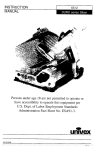
1
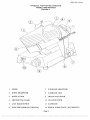
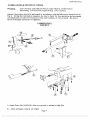
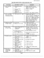
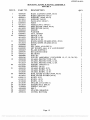
INSTRUCTION
MANUAL
4509, 4510, 4512
I
g,
g
I
i
i
PREP SA
Persons under age 18 are not permitted to operate or
have accessibility to operate this equipment per
U.S. Dept. of Labor Employment Standards
Administration Fact Sheet No. ESA91-3.
univex
4509/10/12 1104
ED7
PDF compression, OCR, web optimization using a watermarked evaluation copy of CVISION PDFCompressor
4509/4510/4512
TO INSU RE BOTH SAFE AND
TROUBLE-FREE PERFORMANCE WE STRESS
THAT ALL PERSONNEL THAT WILL BE
INVOLVED WITH YOUR NEW UNIVEX SLICER
MUST, READ AND UNDERSTAND THESE
INSTRUCTIONS BEFORE ATTEMPTING TO
OPERATE THIS UNIT.
WE APPRECIATE YOUR COOPERATION AND
YOUR BUSINESS. SHOULD THERE BE A
QUESTION OR IF WE CAN BE OF FURTHER
ASSISTANCE, PLEASE CALL US,
1-603-893-6191.
PDF compression, OCR, web optimization using a watermarked evaluation copy of CVISION PDFCompressor
4509/4510,4312
TABLE QE CONTENTS
DESCRIPTION
PAGE
Table of Contents
1
List of Illustrations
1
Introduction
3
Installation Instruction
3
Safety Warnings
3-4
Operating Instructions
4
Sharpening Instructions
5
Operator's Care of Slicer Cleaning and Lubrication
6-7
Mechanics Maintenance
8
Trouble Shooting Guide
9
Repair Instructions including Disassembly, Replacement, and Reassembly
10
Replacement Parts Lists Keyed to Figure Drawings
13 - 19
Wiring Diagram
12
20
Warranty Information
Back Cover
LIST OF ILLUSTRATIONS
ILLUSTRATION
PAGE
Figure 1
Overall View of Meat Slicer Model 4509/4510/4512
2
Figure 2
Lubrication Diagram and Instructions
7
Figure 3
Housing, Knife, and Fence Assembly
Figure 4
Carriage Arm Assembly
is
Figure 5
Carriage Assembly
16
Figure 6
Slice Adjustment Knob Assembly
17
Figure 7
Motor and Electrical Assembly
is
Figure 8
Sharpener Assembly
19
Figure 9
Wiring Diagram 115V, 60Hz, 1 PH, 230v, 60HZ, 1PH,
230V, 50HZ, 1PHV
20
13 - 14
Page 1
PDF compression, OCR, web optimization using a watermarked evaluation copy of CVISION PDFCompressor
4509/4510/4512
OVERALL VIEW OF MEAT SLICER
MODEL 4509/4510/4512
FIGURE 1
1
FENCE
7
CARRIAGE ARM KNOB
2
KNIFE SHARPENER
8
CARRIAGE ARM
3
KNIFE GUARD
9
GRADUATED KNOB
4
PROTECTIVE GUARD
10 ON-OFF SWITCH
5
LAST SLICE DEVICE
11 CARRIAGE
6
ELECTRIC CORD (NOT SHOWN)
12 SERIAL NAME PLATE (NOT SHOWN)
Page 2
PDF compression, OCR, web optimization using a watermarked evaluation copy of CVISION PDFCompressor
4509/4510,4512
INSTRUCTION MANUAL
INTRODUCTION
This manual contains instructions for the Installation, Operation, Care, Maintenance and
Repair of the Meat Slicing Machine. Disassembly, Repair, Replacement and Reassembly
Instructions are included. A trouble shooting guide is provided. A complete Replacement
Parts List with identifying figures is also included to facilitate identification and ordering
of replacement parts.
INSTALLATION INSTRUCTIONS
INSPECTION
All Univex slicers are inspected and tested at the factory; however, they should be
reinspected carefully by the person making the installation for loose, damaged or broken
parts. Detached parts and fixtures should be checked against packing list to determine all
are present. Any damages, imperfections or shortages should be reported to the dealer or
Univex and shipping carrier.
Warning: After slicer has been inspected, wash slicer completely with warm water and
mild soap. For SAFETY, follow the cleaning instructions on Page 6.
INSTALLATION
The most efficient installation of your Univex slicer will depend upon the layout of your
kitchen. Locate your slicer where it will save steps for the operator and be sure to provide
sufficient clearance around it for ease of maintenance and cleaning, as well as for efficient
and safe use.
Slicer should be operated on a sturdy bench or table with the height determined to suit the
operator. It is most important that the forearm of the operator be at the proper level for
ease and safety of operation, as well as for maximum production. This height is considered
optimum when the carriage handle (Figure 1 [8]) of the slicer is at approximately the height
of the operator's elbow when standing.
IMPORTANT
Warning/CautIon: Electrical wiring instructions are found in the wiring diagram (Figure
7) Before making electrical connections, CHECK the specifications on
the nameplate to make sure that they agree with those on your
electrical service. A grounding type three-terminal plug is provided for
safety. If you do not have a mating receptacle, have a qualified
electrician provide one with grounding provisions in accordance with
local safety codes.
IMPORTANT SAFETY WARNINGS
It is a violation of United States Department of Labor regulations to permit operation of the
slicer by any person under the age of 18 years.
Warning: The slicer knife is extremely sharp! Never touch the knife, always keep hands
and fingers clear of the knife. Never run slicer without the guard and all other
parts in place and securely fastened. Take extra care to avoid accidents by
keeping the knife guard and sharpening assembly cover ON at all times. When
Page 3
PDF compression, OCR, web optimization using a watermarked evaluation copy of CVISION PDFCompressor
4509/45 10/45 12
the machine is not in use, the slice adjustment knob should be turned fully back
to the closed position (beyond "0") so that the knife edge is not exposed.
Observe the cleaning instruction on Page 6 for best results and for safety. Also
remember to always turn off the slicer and disconnect the electrical supply cord
before cleaning.
When slicing, always work the carriage using only the carriage arm handle
(Figure 1 [8]). Do not hold or push the carriage from any other place.
OPERATION INSTRUCTIONS
The Univex slicer is designed to meet the cook's demand for an efficient, sturdy slicer. The
Univex slicer will give unfailing performance over a period of years, when operated and
maintained according to instructions contained herein.
START/STOP SWITCH
The slicer is started by toggling the ON/OFF switch (Figure 1 [10]) to the ON position.
SLICE ADJUSTMENT
Warning: Dial-type knob adjustment (Figure 1 [9]) allows for slice thicknesses ranging
from paper thin up to 1/2". Dial graduations allow you to precisely set up
specific slice thicknesses for various needs. When not in use, always return
knob back to its fully closed position (beyond "0") so that the knife edge is not
exposed.
POSITIVE HOLD CARRIAGE
Caution: A last slice gravity feed grip (Figure 1 [5]) is provided. Do not use this last slice
device to work the carriage back and forth. Use only the carriage arm handle
(Figure 1 [8]).
Always make sure the carriage is positively secured to the slicer by checking to
see that the carriage arm knob (Figure 1 [7]) is fully tightened. Failure to do
this could result in the carriage striking and damaging the knife edge.
PROTECTIVE GUARD
Warning: The protective guard (Figure 1 [4]) covers the knife edge completely except
under the sharpener cover and the forward edge where slicing will be performed.
This forward edge is covered by the edge of the fence, but only when the slice
adjustment is completely closed.
The knife guard (Figure 1 [3]) can be removed for cleaning by unscrewing the
knife guard knob (Figure 3 [11]). For safety, keep the knife guard on at all
times except when cleaning. Never operate the slicer with the knife guard
removed.
Page 4
PDF compression, OCR, web optimization using a watermarked evaluation copy of CVISION PDFCompressor
4509/4510,4512
SHARPENING INSTRUCTIONS
This slicer is equipped with a kmfe having a concave or hollowed surface for superior
slicing quality. Of course, any knife, however superior, must be sharpened regularly and
properly in order to produce not only the highest quality slices, but also to allow it to
maintain its productivity. The knife sharpener (Figure 1 [2]) on this machine is a top
mounted built-in mechanism, designed for simplicity and ease of use.
Warning: The following sharpening procedure will provide high quality sharpening results
and should also be followed for safety considerations:
WarnIng: Keep away from the knife edge.
Completely close the slice adjustment (beyond '0") so that the knife edge is
not exposed.
The knife cutting area should be clean and free from food, especially grease.
Grease will ruin the ability of a grinding stone to sharpen an edge. The stone
simply will not cut. If cleaning is necessary, follow the procedure outlined on
Page 6.
Loosen sharpener knob assembly (Figure 8 [4]) which bears against sharpener
post, then lift sharpener assembly (Figure 1 [2]) and rotate it 1/2 turn (180°).
Then force it down over the knife.
Tighten sharpener knob assembly (Figure 8 [4]). As the knob assembly is
tightened, it bears on the sharpener post and automatically aligns the grinding
and deburring stones to the precise orientations which are preset at our
factory.
Turn slicer
This will start the grinding process. Run until the beveled
cutting surface (back side of blade) cleans up. This can take from 30 seconds
to several minutes depending on how dull the blade was allowed to become.
Turn slicer OFF.
Check for the formation of a very slight burr on the side of knife opposite the
bevel (front side of blade) which indicates complete grinding of the bevel.
This slight burr can be detected either visually or by picking with a small
piece of stiff paper.
Turn slicer ON. Lightly press deburring (honing) button (Figure 8 [15]) of
the sharpener assembly and hold for 1 to 2 seconds while you turn OFF the
slicer. Blade should now be completely sharpened and honed.
Caution: It is important for best slicing results not to deburr the knife too
long or the keen edge will be destroyed due to the formation of
an undesirable second bevel on the opposite side. This
condition tends to be the primary cause of unsatisfactory slicing
results.
Turn slicer OFF. Loosen knob assembly, (Figure 8 [4]) then lift and return
sharpener to its storage position. Tighten knob assembly.
Clean slicer and knife according to the cleaning procedure on Page 6 in order
to thoroughly remove grinding debris.
Page 5
PDF compression, OCR, web optimization using a watermarked evaluation copy of CVISION PDFCompressor
4509/451014512
OPERATORS CARE OF SLICER
CLEANING
Warning:
1.
Never touch the knife edge. Always keep your hands, fingers and
arms clear of knife.
Warning:
2.
Turn off slicer and DISCONNECT ELECTRICAL CORD before
cleaning. Leave protective guard (Fig. 1 [4]) in place,
3.
Turn slice adjustment knob (Figure 1 [9]) to the fully closed position
(beyond "O") so that the knife edge is not exposed.
4.
Remove carriage assembly (Figure 1 [5, 8, 11]) by loosening carriage
knob (Figure 1 [7]) and lifting off. Carriage may be washed in a
sink. Use care in washing the sharply pointed prongs on the last slice
device, (Figure 1 [5]). Wash this area thoroughly. A small bristle
brush is recommended. Use only warm water and mild soap. Rinse
carriage assembly with warm water and dry thoroughly using a clean
soft cloth.
Caution:
Never use detergents or wash the slicer or any of its parts in a dish
washing machine or the clear protective finish will be damaged.
Warning
5.
Wash body of slicer using warm water and mild soap using a clean
soft cloth. Under no circumstances should the slicer be hose rinsed.
It is recommended that the cloth be folded over a thin wooden stick
when cleaning between the fence and the knife.
Remove knife guard (Figure 1 [3]) by loosening knife guard knob
(Figure 3 [11]) and pushing the long stud upward to lift knife guard
above surface of knife. Then carefully lift and remove guard.
Remove knife deflector (Fig. 3 [6]) by unscrewing screw (Fig. 3 [7]).
Warning:
8.
CAREFULLY wash the front and rear of the knife with a cloth using
warm water and mild soap. It is recommended that the cloth be
folded over a thin wooden stick as a further caution to avoid
accidental contact with the knife edge. CAREFULLY wash between
the knife edge and protective guard (Figure 1 [4]) using a soft cloth
inserted between knife edge and guard on both front and rear of knife
using extreme caution to never touch the knife edge. Rinse with
warm water applied with a cloth. Dry thoroughly with a clean soft
cloth.
Caution:
9.
Following cleaning, a commercial nontoxic sanitizer may be wiped on
the clean surfaces with a soft clean cloth or sprayed as recommended
on the container labeling. It is important that the sanitizer be
compatible with anodized aluminum or the clear protective finish on
the slicer will be damaged. Surface should be wetted completely, but
not to the point of running or puddling.
Warning:
10.
Replace the knife guard. Never leave the slicer without its knife
guard installed!
11.
Replace knife deflector.
Page 6
PDF compression, OCR, web optimization using a watermarked evaluation copy of CVISION PDFCompressor
4509/4510,4512
LUBRICATION & FUNCTION ChECK
Warning:
Turn oft' slicer and DISCONNECT ELECTRICAL CORD before
lubricating. Leave protective guard (Fig. i [4]) in place.
General lubrication should be performed in accordance with the lubrication instructions in
Fig. 2. During this lubrication sequence, be sure to check for free operation and movement
of related parts as well as for excessive wear and looseness of various parts. Be sure to
check all handles and knobs for tightness.
LUBRICATION
FIGURE 2
A -Apply Petro-Gel (4400408) often as required to maintain light film.
B - Clean and apply mineral oil weekly
Page 7
PDF compression, OCR, web optimization using a watermarked evaluation copy of CVISION PDFCompressor
450914510/4512
MECHANICS MAINTENANCE
Every year a mechanic or service technician should perform the following inspection and
carry out the respective maintenance as required:
Warning
FOR SAFETY, TURN OFF SLICER AND DISCONNECT ELECTRICAL
CORD.
BELT DRIVE This drive features a multi-ribbed high performance belt for
long trouble-free service. Inspect belt for proper tension. If worn, replace. If
tension requires adjustment, it may be obtained by loosening nut (Fig. 7 [2))
and turning screw (Fig. 7 [3)) clockwise until desired tension is achieved.
Holding screw (Fig. 7 [3)) stationary, tighten nut (Fig. 7 [2]) against motor
casing.
CARRIAGE - Check for free smooth operation of last slice device and for
smooth travel of carriage arm (Fig. 4 [2)). Check for excess backlash between
slide bearing (Fig. 4 [10)) and carriage slide bar (Fig. 4 [8]). The correct lash
(clearance) required for smooth carriage operation is obtained when a very
slight lash or movement can be detected. Too much lash can result in the
carriage striking and damaging the knife edge. Too little lash results in
binding and a loss of smoothness in carriage travel. Lash is adjusted by
loosening locknut (Fig. 4 [14]) and turning set screw (Fig. 4 [15)) clockwise
to reduce lash and counterclockwise to increase lash, Tighten locknut while
holding nylon tipped stud stationary with a screwdriver so it does not move.
Grease only the side of the carriage slide (Fig. 4 [8]) on which this set screw
slides. General guidelines: tighten screw until snug and then loosen 1/8 turn
and tighten locknut as described above
LUBRICATION & FUNCTION CHECK - General lubrication should be
performed in accordance with the lubrication instructions in Fig. 2. During
this lubrication sequence, be sure to check for free operation and movement of
related parts as well as for excessive wear and looseness of various parts. Be
sure to check all handles and knobs for tightness.
KNIFE - Check knife edge to see that it has been properly sharpened. If there
is any evidence of incorrect sharpening procedure, such as excessive honing,
alert owner and operator.
Page 8
PDF compression, OCR, web optimization using a watermarked evaluation copy of CVISION PDFCompressor
4509/4510,4512
TROUBLESHOOTING GUIDE 4509/4510/4512
TROUBLE
L Slicer will not
operate.
POSSIBLE CAUSE
1.1 Electrical service
down.
1.2 Burned switch
contacts.
1.3 Motor capacitor
defective.
1.4 Burned out motor.
REMEDY
1.1 Check electrical service.
Replace fuse or reset circuit
breaker as necessary.
1.2 Replace switch.
1.3 Replace
1,4 Remove, test, repair or replace.
2. Motor straining
but will not turn
(humming sound).
2.1 Belt tension too tight. 2.1 Readjust belt tension.
NOTE: Often after a long period
of no use, such as in storage, the
belt flows and takes a set in the
pulley ribs. A slight urging of the
knife with a wooden stick will
get the slicer turning with no
further problems. Do not use
hands to turn the knife.
3. Slippage of knife
during slicing.
3.1 Loose belt.
3.2 Grease or oil on belt.
4. Motor stalls
during slicing,
4.1 Knife cutting edge dull 4.1 Sharpen using the procedure
or improperly
specified. Use care not to use
sharpened
honing stone longer than the 1
to 2 seconds.
4.2 Product such as cheese 4.2 Reduce thickness of slice.
old and dried out.
4.3 Low voltage service
4,3 Have electrician check service
voltage.
4.4 Belt tension excessive. 4.4 Readjust belt tension.
5. Excessive noise.
5.1 Knife contacting the
knife guard.
5.2 Badly worn or frayed
drive belt.
5.3 Motor pulley and belt
misaligned.
5.4 Loose set screw in
motor pulley.
5.5 Knife contacting
deflector.
5.6 Knife contacting
sharpener.
5.7 Carriage contacting
fence or knife.
5.1 Tighten knob which secures
guard.
5.2 Replace belt.
6.1 Soft cheese is at room
temperature.
6.2 Knife dirty with hard
dried-on product.
6.1 ChilI soft cheese for best slicing
results.
6.2 Clean knife thoroughly.
6. Smearing or
tearing when
slicing soft
cheese.
3.1 Tighten belt tension.
3.2 Clean pulleys with safety
approved cleaning solvent on
soft clean rag. Replace belt.
53. Realign motor pulley.
5.4 Tighten set screw.
5.5 Adjust deflector.
5.6 Adjust sharpener.
5.7 Tighten knob which secures
carriage.
Page 9
PDF compression, OCR, web optimization using a watermarked evaluation copy of CVISION PDFCompressor
4509/4510/4512
REPAIR INSTRUCTiONS
Including disassembly, replacement, and reassembly.
Warning: Always turn off slicer and disconnect electrical cord before doing any
maintenance or repair on the slicer. Keep guards on at all times. Keep slice
adjustment fully closed so knife edge is not exposed. Keep sharpener assembly
also in place so top of knife edge is not exposed.
KNIFE REPLACEMENT (Figure 3)
Warning: Disconnect electrical power cord.
Remove carriage assembly (Figure 1 [8, 11])
Loosen sharpener knob assembly (Figure 8 [4] ), then lift and remove sharpening
unit. Set aside.
Remove knife guard knob (Figure 3 [11]) and carefully remove knife guard
(Figure 3 [21] ).
Warning: Using caution to avoid the sharp knife edge, remove the three screws
(Figure 3 [20] ) that secure knife (Figure 3 [23] ).
Carefully remove knife and set aside with its flat side down flush on a bench so
the edge is not exposed.
Reinstall new knife in the reverse procedures outlined above.
Even though a new knife is very sharp, the sharpening procedure specified on
page 5 should be performed to true the new knife's bevel to the slicer.
Warning: Worn knife should be disposed of in a safe responsible way, showing concern
for others who may handle it. It is recommended that the edge of the knife be
wrapped several times with heavy tape and that a caution (CAUTION: SHARP
EDGE) be written on both sides of the knife.
SHARPENING STONES
Warning: Disconnect electrical cord.
Unscrew sharpener knob assembly (Figure 8 [4] ).
Lift up sharpening assembly (Figure 1 [2] ) and remove from slicer.
Using an open end wrench, unscrew cover knob (Figure 8 [8]). It is
recommended that a piece of tape or paper be temporarily wrapped around knob
prior to unscrewing it so as to protect its finish. Remove cover (Figure 8 [9]) off
of mount assembly.
Unscrew nut (Figure 8 [21] ) and remove along with washer and sharpening
stone (Figure 8 [23] ).
Install new sharpening stone. Hollowed side should be toward the outside.
Page 10
PDF compression, OCR, web optimization using a watermarked evaluation copy of CVISION PDFCompressor
4509/4510,4512
Honing (deburring) stone (Figure 8 [18) ) is removed by first unscrewing lock
screw (Figure 8 [14] ) from button (Figure 8 El 5]).
Gently remove button taking care to not lose the small ball bearing and spring
(Figure 8 [16 & 17] ) which are inside.
Unscrew nut (Figure 8 [13] ) and remove along with washer and honing stone
(Figure 8 [18] ).
Install new honing stone with the hollowed side toward the inside.
Reattach cover and reinstall in the reverse procedures (4. through 1.).
DRIVE BELT REPLACEMENT
WarnIng: Disconnect electrical power cord.
Remove knife per knife replacement instructions.
Remove four rubber suction feet (Figure 3 [4] ) that secure bottom cover (Figure
3 [29] ) to slicer. Remove cover.
Loosen nut (Figure 7 [2) ) on motor adjustment screw (Figure 7 [1] ). Loosen
motor adjustment screw
Loosen set screws (Figure 7 [15 & 17]). Slide motor pivot rod (Figure 7 [16)) to
the right (towards the blade) until left end of rod disengages with base casting.
Page 11
PDF compression, OCR, web optimization using a watermarked evaluation copy of CVISION PDFCompressor
4509/4510,4512
Pivot motor to unwrap belt from motor pulley shaft.
Remove drive belt through the knife pulley opening in base casting.
Install replacement belt on knife pulley and on motor pulley shaft. DO NOT
reinstall knife at this time.
Reinstall motor pivot rod. Tighten set screw (Figure 7 [15]).
Position the pivot rod collar (End of motor shaft should be 1/16 - 1/8" away
from base casting. If not slide motor along rod accordingly.) Tighten collar set
screw (Figure 7 [17]),.
Align belt on motor shaft and knife pulley.
Tighten motor adjustment screw (Figure 7 [3]) until adequate belt tension is
acquired. DO NOT over tighten. Tighten jam nut (Figure 7 [2]).
Connect electrical power cord and operate slicer to check that belt and pulley
are running true.
Turn off slicer and disconnect electrical power cord.
Reinstall bottom cover and secure with the four suction feet.
Using caution, reinstall knife and secure wìth three screws.
Reinstall knife guard and secure with knife guard knob.
Reinstall sharpener and secure with knob assembly.
Page 12
PDF compression, OCR, web optimization using a watermarked evaluation copy of CVISION PDFCompressor
4509/4510/4512
HOUSING. KNIFE & FENCE ASSEMBLY
FIGURE 3
ILLUS.
1
2
3
4
5
6
7
8
9
10
11
12
13
14
15
16
17
18
19
20
21
22
23
24
25
26
27
28
29
PART NO.
DESCRIPTION
4509020
4512020
4509021
4512021
4512032
6509093
4512031
4509022
4512022
6509024
4509066
6509081
4509023
4510023
4512023
4509024
4512024
6509080
4509058
6509089
4509085
4509059
4509027
4509086
4509026
4509028
4510028
4512025
8512229
8512229
4509029
4510029
4512026
4509030
4512027
6509013
6510013
4512028
4512030
4512029
7510008
4509088
4509087
4509034
BASE. CASTING (4509, 4510)
BASE CASTING (4512)
SUPPORT (4509, 4510)
SUPPORT (4512)
PLUG (4512 ONLY)
FOOT
SHIELD (4512 ONLY)
DEFLECTOR (4509, 4510)
DEFLECTOR (4512)
SCREW
WASHER
NUT, ACORN
FENCE, 9 IN.
FENCE, 10 IN.
FENCE, 12 IN.
QTY
1
1
1
2
4
1
1
1
2
1
1
1
1
KNOB, KNIFE GUARD (4509, 4510)
KNOB, KNIFE GUARD (4512)
1
1
STUD
PIN (4509, 4510 ONLY)
SET SCREW, M6-1.0 X 14 CUP POINT
BLADE SUPPORT
RETAINING RING
BEARING
PULLEY
2
1
2
1
PULLEY ASSEMBLY (INCLUDES 15, 17, 18, 26, 28)
GUARD, PROTECTIVE, 9 IN.
GUARD, PROTECTIVE, 10 IN.
GUARD, PROTECTIVE, 12 IN.
SCREW, (4509,4510)
SCREW, (4512)
GUARD, KNIFE, 9 IN.
GUARD, KNIFE, 10 IN.
GUARD, KNIFE, 12 IN.
ROD, KNIFE GUARD (4509, 4510)
ROD, KNIFE GUARD (4512)
KNIFE, 9 IN.
KNIFE, IO IN.
KNIFE, 12 IN.
SPACER (4512 ONLY)
SCREW (4512 ONLY)
INSERT, PULLEY
BELT
SPACER, BEARING
COVER, BOTTOM
1
1
7
5
1
1
1
1
1
1
1
2
2
1
1
Page 13
PDF compression, OCR, web optimization using a watermarked evaluation copy of CVISION PDFCompressor
450914510,4512
HOUSING, KNIFE & FENCE ASSEMBLY
FIGURE 3
Page 14
PDF compression, OCR, web optimization using a watermarked evaluation copy of CVISION PDFCompressor
4509/4510/4512
CARRIAGE A1M ASSEMBLY
FIGURE 4
ILLUS.
1
2
3
4
5
6
7
8
9
10
11
12
13
14
15
16
17
PART NO.
DESCRIPTION
6509017
4509053
4510053
4512033
6509080
7510035
4509065
4509054
4509089
4509055
1204004
4509069
1200076
4509056
4509057
6509074
6509073
8512308
6509054
KNOB, CARRIAGE ARM
ARM, CARRIAGE 4509
ARM, CARRIAGE 4510
ARM. CARRIAGE 4512
SCREW, ARM ATTACHMENT
SCREW
SPRING
ROD, ARM
SPACER
BAR, FRAME
SCREW, M5-0,8 X 16
BEARING
WASHER
BUSHING, ARM
BUSHING
NUT
SET SCREW
SCREW, HX HD M8-1.25 X 28
HANDLE
QTY
I
1
1
4
3
1
2
1
1
2
5
1
2
1
1
1
1
Page 15
PDF compression, OCR, web optimization using a watermarked evaluation copy of CVISION PDFCompressor
4509/4510,4512
CARRIAGE ASSEMBLY
FIGURE 5
ILLUS.
1
2
3
4
5
6
7
8
9
10
11
12
13
14
15
16
PART NO.
DESCRIPTION
4400410
4512046
NUT, M8 (4509,4510)
NUT, MiO (4512)
QTY
1
1
RESERVED
8512439
6509059
4509048
6512035
4509063
6509160
4509051
4512034
4509075
4512035
6509153
4509052
6509049
6509080
4512036
7120129
4512037
4512038
4512051
4512052
4512953
4512054
WASHER (4509, 4510)
WASHER (4512)
CARRIAGE (4509, 4510)
CARRIAGE (4512)
NYLON TIP (4509, 4510)
NYLON TIP (4512)
LAST SLICE DEVICE (4509, 4510)
LAST SLICE DEVICE (4512)
HANDLE (4509, 4510)
HANDLE (4512)
KNOB (4512 ONLY)
SHAFT, LAST SLICE DEVICE (4509, 4510)
SHAFT, LAST SLICE DEVICE (4512)
STUD, M8-L25 X 30 (MODIFIED) (4509, 4510)
STUD (4512)
STUD, M6-1.0 X20 (4509, 4510)
STUD, (4512)
SCREW, M6-1.0 X 12 (4512 only)
CAM STOP (4512 only)
SCREW FLAT HD SS M6 X 1MM (4512 ONLY)
SLEEVE PLASTIC (4512 ONLY)
PIN (4512 ONLY)
1
1
1
1
1
1
1
1
1
1
1
1
1
1
1
1
1
2
1
Page 16
PDF compression, OCR, web optimization using a watermarked evaluation copy of CVISION PDFCompressor
4509/4510/4512
SLICE ADJUSTMENT KNOB ASSEMBLY
FIGURE 6
ILLUS.
1
2
3
4
5
6
7
8
9
10
11
12
13
14
15
16
17
18
19
20
21
22
23
24
PART NO.
DESCRIPTION
4509090
6509059
4509044
4509045
1204001
6509074
1204043
4509046
1204005
6509040
4509061
7510021
6509072
4400116
6509098
4512042
KNOB, SLICE ADJ
WASHER, SLICE ADJ
SPRING, SLICE ADJ
GUIDE
SCREW SOC HD CAP M6-l.0 X 12
NUT, M6-1.0
STUD, M6-1.0 X 11
SHAFT
SCREW, SOC HD CAP M6-1.0 X 20
SCREW, M6-1.0 X 30
STUD (4509, 4510 ONLY)
WASHER (4509, 4510 ONLY)
NUT, M8-1.25 (4509, 4510 ONLY)
6509061
4509068
4509070
4509062
4509047
4512039
6509041
4512041
4512040
ROLLPIN (4509, 4510 ONLY)
QTY
I
1
1
3
2
I
1
I
3
1
1
1
1
SET SCREW
SCREW M6-1.0 X 8 NYLON SLOTTED SS FLAT PT
(4512 ONLY)
SPRING
WASHER
2
CAM
1
PIN (4509, 4510 ONLY)
SUPPORT, FENCE HOLDER (4509, 4510)
SUPPORT, FENCE HOLDER (4512)
1
WASHER
1
STUD, (4512 ONLY)
PIN (4512 ONLY)
1
1
1
1
1
1
1
REPLACES
LLUS. 20
FOR 4512 ONLY
Page 17
PDF compression, OCR, web optimization using a watermarked evaluation copy of CVISION PDFCompressor
4509/4310,4512
ILLUS.
1
2
3
4
5
6
7
8
9
10
11
12
13
14
15
16
17
18
19
20
PART NO.
4509073
4512043
4509077
4509078
6509115
6509074
1204002
4512044
4509041
1204042
6509074
4509072
4509076
1204020
4509074
7120009
7129011
4400081
4400053
8800210
1012042
6509089
4509060
6509098
4509091
4400237
4400227
MOTOR & ELECTRICAL ASSEMBLY
FIGURE 7
DESCRIPTION
MOTOR, 115V, 60HZ, 1PH (4509, 4510)
MOTOR, 115V, 60HZ, 1PH (4512)
MOTOR, 230V, 60HZ, IPH (4509, 4510)
MOTOR, 230V, 50HZ, 1PH (4509, 4510)
NUT, M5-0.8 (4509, 4510)
NUT, (4512)
SCREW, SLOT PAN HD M5-0.8 X 45(4509, 4510)
SCREW, M6-1.0 X 70 (4512)
CLAMP, CAPACITOR
STUD, M6-1.0 X 30, CAPACITOR BRACKET
NUT, M6-1,0
CAPACITOR 115V/60/1
CAPACITOR 220V/50-60/1
LOCK WASHER, M6
WIRE, MOTOR GROUND
SWITCH
GUARD, SWITCH
PIN, SWITCH GUARD
CORD, POWER
CORD, POWER
STAIN RELIEF
SET SCREW
ROD, MOTOR
SET ,SCREW
COLLAR
QTY
1
1
1
1
1
1
1
I
2
4
2
1
1
1
2
1
1
1
1
2
2
CANADA ONLY
CIRCUIT BREAKER (NOT SHOWN)
LABEL, RESET (NOT SHOWN)
Page 18
PDF compression, OCR, web optimization using a watermarked evaluation copy of CVISION PDFCompressor
4509/4510/4512
SHARPENER ASSEMBLY
FIGURE 8
ILLUS. NO.
PART NO.
DESCRIPTION
27
28
4509065
6509041
8512852
4509035
6509124
6509125
6509137
4509036
4509037
6509150
4509038
6509132
6509131
6509136
6509135
6509133
6509134
4509092
6509129
6509128
6509143
8512516
4509093
4509039
6509127
6509147
6509126
4509040
STUD, SHARPENER SUPPORT
WASHER
NUT, ACORN
KNOB, ASSEMBLY
PIN, SET
WASHER, PIN, SET
SCREW
KNOB
COVER
NUT
SPACER
WASHER
NUT
SCREW
BUTTON, STONE DEPRESS
BALL
SPRING
STONE, HONING
STUD, HONING
BUSHING
NUT
WASHER
STONE, SHARPENING
STUD, SHARPENING
SPRING
STUD MOUNTING
MOUNT
SUPPORT, SHARPENER 4509
29
4510040
4512045
4509066
SUPPORT, SHARPENER 4510
SUPPORT, SHARPENER 4512
WASHER
1
2
3
4
5
6
7
8
9
10
11
12
13
14
15
16
17
18
19
20
21
22
23
24
25
26
QTY
1
1
1
1
1
i
2
1
1
1
1
1
1
1
1
1
1
1
1
I
1
1
2
1
1
1
1
1
Page 19
PDF compression, OCR, web optimization using a watermarked evaluation copy of CVISION PDFCompressor
450914510,4512
WIRING DIAGRAM MODEL 4509/4510/4512
115V, 60HZ, 1PH
23QV, 60HZ, 1PH
230V, 50HZ, 1PH
FIGURE 9
/
POWER IN
CAPACITOR
OHO
WHITE
WHITE
SWITCH
BLACKE TWHITE
i
-1
BLACK
o
GREEN/YELLOW
GREEN
CANADA ONLY
115V, 60HZ, 1PH
CIRCUI T
/
BREAKET
POWER IN
\
CAPACI TOR
2
ÇT1
SWITCH
WHITE
L
GREEN
o
J
WHITE
WHITE
BLACK
BLACK
BLACK
MOTOR
GREEN/YELLOw
IMPORTANT
Warning: Before making electrical connections, check the specifications on the data plate
to assure they agree with those of your electrical service.
Whenever cleaning or maintenance is being performed, DISCONNECT
electrical cord.
Page 20
PDF compression, OCR, web optimization using a watermarked evaluation copy of CVISION PDFCompressor