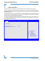
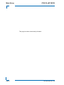
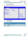
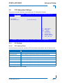
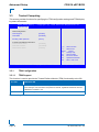
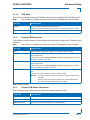
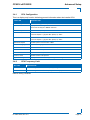
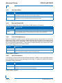
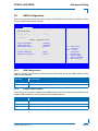
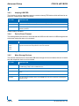
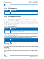
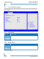
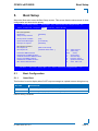
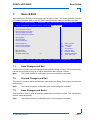
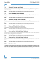
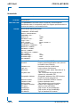
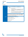
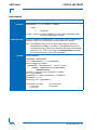
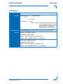
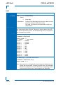
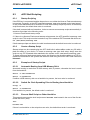
1
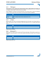
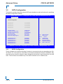
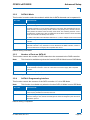
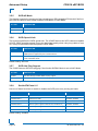
» User Guide « CP6016 uEFI BIOS Doc. ID: 1022-7205, Rev. 2.0 May 12, 2011 If it’s embedded, it’s Kontron. Preface CP6016 uEFI BIOS Revision History Publication Title: CP6016 uEFI BIOS uEFI BIOS User Guide Doc. ID: 1022-7205 Rev. Brief Description of Changes Date of Issue 1.0 Initial issue based on the uEFI BIOS version R13 2-Oct-2011 2.0 Added information about to the SATA port routing in Chapter 3.5.8. 12-May-2011 Imprint Kontron Modular Computers GmbH may be contacted via the following: MAILING ADDRESS TELEPHONE AND E-MAIL Kontron Modular Computers GmbH +49 (0) 800-SALESKONTRON Sudetenstraße 7 [email protected] D - 87600 Kaufbeuren Germany For further information about other Kontron products, please visit our Internet website: www.kontron.com. Disclaimer Copyright © 2011 Kontron AG. All rights reserved. All data is for information purposes only and not guaranteed for legal purposes. Information has been carefully checked and is believed to be accurate; however, no responsibility is assumed for inaccuracies. Kontron and the Kontron logo and all other trademarks or registered trademarks are the property of their respective owners and are recognized. Specifications are subject to change without notice. Page ii ID 1022-7205, Rev. 2.0 CP6016 uEFI BIOS Preface Table of Contents Revision History .........................................................................................................ii Imprint ........................................................................................................................ii Disclaimer ..................................................................................................................ii Table of Contents ...................................................................................................... iii 1. Starting uEFI BIOS Setup ....................................................... 1 - 3 1.1 Main Setup Menu .................................................................................... 1 - 4 2. Main Setup ............................................................................... 2 - 9 2.1 BIOS Information ..................................................................................... 2 - 9 2.2 Memory Information ................................................................................ 2 - 9 2.3 System Language ................................................................................. 2 - 10 2.4 System Date .......................................................................................... 2 - 10 2.5 System Time ......................................................................................... 2 - 10 2.6 Access Level ......................................................................................... 2 - 10 3. Advanced Setup .................................................................... 3 - 13 3.1 Legacy OpROM .................................................................................... 3 - 13 3.1.1 Launch PXE OpROM .................................................................... 3 - 13 3.1.2 Use Device for PXE ...................................................................... 3 - 14 3.1.3 Launch Storage OpROM .............................................................. 3 - 14 3.1.4 Boot Video .................................................................................... 3 - 14 3.2 PCI Subsystem Settings ....................................................................... 3 - 15 3.2.1 PCI Settings .................................................................................. 3 - 15 3.2.1.1 PCI Latency Timer ............................................................... 3 - 15 3.3 Trusted Computing ................................................................................ 3 - 16 3.3.1 TPM Configuration ........................................................................ 3 - 16 3.3.1.1 TPM Support ........................................................................ 3 - 16 3.3.1.2 TPM State ............................................................................ 3 - 17 3.3.2 Pending TPM Operation ............................................................... 3 - 17 ID 1022-7205, Rev. 2.0 Page iii PRELIMINARY 1.2 Navigation ............................................................................................... 1 - 5 Preface 3.3.3 CP6016 uEFI BIOS Current TPM Status Information ....................................................3 - 17 PRELIMINARY 3.4 CPU Configuration .................................................................................3 - 18 3.4.1 CPU Configuration ........................................................................3 - 19 3.4.2 CPU Frequency Limit ....................................................................3 - 19 3.4.3 Intel SpeedStep .............................................................................3 - 20 3.4.4 Execute Disable Bit .......................................................................3 - 20 3.4.5 Limit CPUID Maximum ..................................................................3 - 20 3.4.6 Intel Virtualization ..........................................................................3 - 20 3.4.7 TM Support ...................................................................................3 - 21 3.4.8 C-States ........................................................................................3 - 21 3.4.9 Enhanced C1 ................................................................................3 - 21 3.5 SATA Configuration ...............................................................................3 - 22 3.5.1 SATA Configuration .......................................................................3 - 22 3.5.2 SATA #1 Mode ..............................................................................3 - 23 3.5.3 Number of Ports on SATA #1 ........................................................3 - 23 3.5.4 SATA #1 Programming Interface ...................................................3 - 23 3.5.5 SATA #2 Mode ..............................................................................3 - 24 3.5.6 SATA Speed Limit .........................................................................3 - 24 3.5.7 SATA Hot Plug Support .................................................................3 - 24 3.5.8 Serial-ATA Ports 0..5 .....................................................................3 - 24 3.6 USB Configuration .................................................................................3 - 25 3.6.1 USB Configuration ........................................................................3 - 25 3.6.2 Legacy USB Support .....................................................................3 - 25 3.6.3 Hotplug USB FDD .........................................................................3 - 26 3.6.4 Device Reset Timeout ...................................................................3 - 26 3.6.5 Mass Storage Devices ..................................................................3 - 26 3.7 Serial Port Console Redirection .............................................................3 - 27 3.7.1 3.7.1.1 Console Redirection .............................................................3 - 27 3.7.1.2 Console Redirection Settings ...............................................3 - 27 3.7.2 COM1 ............................................................................................3 - 28 3.7.2.1 Console Redirection .............................................................3 - 28 3.7.2.2 Console Redirection Settings ...............................................3 - 28 3.7.3 Page iv COM0 ............................................................................................3 - 27 Serial Port for Out-of-Band Management/Windows EMS .............3 - 28 ID 1022-7205, Rev. 2.0 CP6016 uEFI BIOS 3.7.3.1 Console Redirection ............................................................. 3 - 28 3.7.3.2 Out-of-Band Mgmt Port ........................................................ 3 - 28 3.7.3.3 Data Bits ............................................................................... 3 - 28 3.7.3.4 Parity .................................................................................... 3 - 28 3.7.3.5 Stop Bits ............................................................................... 3 - 29 3.7.3.6 Terminal Type ....................................................................... 3 - 29 Console Redirection Settings ....................................................... 3 - 30 3.7.4.1 Terminal Type ....................................................................... 3 - 30 3.7.4.2 Bits per second .................................................................... 3 - 30 3.7.4.3 Data Bits ............................................................................... 3 - 31 3.7.4.4 Parity .................................................................................... 3 - 31 3.7.4.5 Stop Bits ............................................................................... 3 - 31 3.7.4.6 Flow Control ......................................................................... 3 - 31 3.7.4.7 Terminal Resolution .............................................................. 3 - 31 Chipset Setup ........................................................................ 4 - 35 4.1 SouthBridge Configuration .................................................................... 4 - 36 4.1.1 ICH9R Device Configuration ......................................................... 4 - 36 4.1.1.1 4.1.2 High Precision Event Timer Configuration .................................... 4 - 37 4.1.2.1 4.1.3 5. Azalia HD Audio ................................................................... 4 - 36 High Precision Event Timer .................................................. 4 - 37 USB Configuration ........................................................................ 4 - 37 4.1.3.1 UHCI Configuration .............................................................. 4 - 37 4.1.3.2 UHCI Controller 1..3 ............................................................. 4 - 37 4.1.3.3 UHCI Controllers 4..6 ........................................................... 4 - 38 4.1.3.4 USB 2.0 (EHCI 1) Support ................................................... 4 - 38 4.1.3.5 USB 2.0 (EHCI 2) Support ................................................... 4 - 38 Boot Setup ............................................................................. 5 - 41 5.1 Boot Configuration ................................................................................ 5 - 41 5.1.1 Quiet Boot ..................................................................................... 5 - 41 5.1.2 Setup Prompt Timeout .................................................................. 5 - 42 5.1.3 Bootup NumLock State ................................................................. 5 - 42 5.1.4 Option ROM Messages ................................................................ 5 - 42 ID 1022-7205, Rev. 2.0 Page v PRELIMINARY 3.7.4 4. Preface Preface 5.1.5 CP6016 uEFI BIOS Interrupt 19 Capture ......................................................................5 - 42 5.2 Boot Option Priorities .............................................................................5 - 43 6. 5.2.1 Boot Option #1..2 ..........................................................................5 - 43 5.2.2 Hard Drive/Network Device/CD/DVD ROM Drive BBS Prior./etc..5 - 43 Security Setup ....................................................................... 5 - 47 6.1 Administrator Password .........................................................................5 - 48 6.2 User Password ......................................................................................5 - 48 PRELIMINARY 6.3 Remember the Password ......................................................................5 - 48 7. Save & Exit ............................................................................. 5 - 51 7.1 Save Changes and Exit .........................................................................5 - 51 7.2 Discard Changes and Exit .....................................................................5 - 51 7.3 Save Changes and Reset ......................................................................5 - 51 7.4 Discard Changes and Reset ..................................................................5 - 52 7.5 Save Changes (Save Options) ..............................................................5 - 52 7.6 Discard Changes (Save Options) ..........................................................5 - 52 7.7 Restore Defaults (Save Options) ...........................................................5 - 52 7.8 Save as User Defaults (Save Options) ..................................................5 - 52 7.9 Restore User Defaults (Save Options) ..................................................5 - 52 7.10 Boot Override .........................................................................................5 - 52 8. uEFI Shell ............................................................................... 5 - 55 8.1 Introduction, Basic Operation ................................................................5 - 55 8.1.1 Shell Startup ..................................................................................5 - 55 8.2 Kontron Shell Commands ......................................................................5 - 55 8.3 uEFI Shell Scripting ...............................................................................5 - 63 8.3.1 Startup Scripting ............................................................................5 - 63 8.3.2 Create a Startup Script ..................................................................5 - 63 8.3.3 Examples of Startup Scripts ..........................................................5 - 63 Page vi 8.3.3.1 Automatic Booting from USB Memory Stick .........................5 - 63 8.3.3.2 Switch On Clock Spreading Prior to Booting from Harddrive 5 - 63 8.3.3.3 Execute Shell Script on Other Harddrive ..............................5 - 63 ID 1022-7205, Rev. 2.0 Starting uEFI BIOS Setup Chapter 1 Starting uEFI BIOS Setup ID 1022-7205, Rev. 2.0 Page 1 PRELIMINARY CP6016 uEFI BIOS PRELIMINARY Starting uEFI BIOS Setup CP6016 uEFI BIOS This page has been intentionally left blank. Page 2 ID 1022-7205, Rev. 2.0 CP6016 uEFI BIOS 1. Starting uEFI BIOS Setup Starting uEFI BIOS Setup The CP6016 is provided with a Kontron-customized, pre-installed and configured version of Aptio® (referred to as uEFI BIOS in this manual), AMI’s next generation BIOS firmware based on the Unified Extensible Firmware Interface (uEFI) specification and the Intel® Platform Innovation Framework for EFI. This uEFI BIOS provides a variety of new and enhanced functions specifically tailored to the hardware features of the CP6016. To take advantage of these functions, the uEFI BIOS comes with a Setup program which provides quick and easy access to the individual function settings for control or modification of the uEFI BIOS configuration. To start the uEFI BIOS Setup program, follow the steps below: 1. 2. 3. 4. Power on the board. Wait until the first characters appear on the screen (POST messages or splash screen). Press the <F2> key. If the uEFI BIOS is password-protected, a window such as the one below will appear: Enter Password Enter either the User password or the Administrator password (refer to chapter 6, Security Setup for further information), press <RETURN>, and proceed with step 2. 5. A Setup menu with the following token attributes will appear. The currently active menu and the currently active uEFI BIOS Setup item are highlighted in white. ID 1022-7205, Rev. 2.0 Page 3 PRELIMINARY The Setup program allows the accessing of various menus which provide functions or access to sub-menus with more specific functions of their own. The individual menus and the configurable functions are described in this guide. Starting uEFI BIOS Setup 1.1 CP6016 uEFI BIOS Main Setup Menu The Main setup menu is the first screen that appears after starting the Setup program. At the top of this screen and all of the other major screens, there is a setup menu selection bar, which permits access to all of the other major setup menus. These menus are selected via the left-right arrow keys. All setup menu screens have two main frames. The left frame displays all the functions that can be configured. They are displayed in blue. Functions displayed in gray provide information about the status or the operational configuration. The right frame displays the key legend. Above the key legend there is an area reserved for a text message. When an function is selected in the left frame, it is displayed in white. Often a text message will accompany it. PRELIMINARY Aptio Setup Utility - Copyright (C) 2007 American Megatrends, Inc. Ma in A d v a n c e d C h ips e t Boot Security Title (black) Read only field (grey) value Setup item (blue) [value] Save & Exit Pointer to a subordinate menu : Select Screen : Select Item Enter: +/-: F1: F2: F3 F4: Select Change Opt. General Help Previous Values Optimized Defaults Save ESC: Exit Ve r s i o n 1 . 2 3 . 11 0 9 . C o p y r i g h t ( C ) 2 0 0 7 A m e r i c a n M e g a t r e n d s , I n c . Page 4 ID 1022-7205, Rev. 2.0 CP6016 uEFI BIOS 1.2 Starting uEFI BIOS Setup Navigation The CP6016 uEFI BIOS setup program uses a hot key-based navigation system. A hot key legend is located in the right frame on most setup screens.The following table provides information concerning the usage of these hot keys. HOT KEY DESCRIPTION <F1> The <F1> key is used to invoke the General Help window. <F2> The <F2> key is used to restore the previous values. <F3> The <F3> key is used to load the defaults. <F4> The <F4> key is used to save the current settings and exit the uEFI BIOS Setup. Left/Right The Left and Right <Arrow> keys are used to select a major Setup screen. For example: Main Screen, Advanced Screen, Chipset Screen, etc. Up/Down The Up and Down <Arrow> keys are used to select a Setup function or a sub-screen. + - Plus/Minus The Plus and Minus <Arrow> keys are used to change the field value of a particular Setup function, for example, system date and time. <ESC> The <ESC> key is used to exit a menu or the uEFI BIOS Setup. Pressing the <ESC> key in a sub-menu causes the next higher menu level to be displayed. When the <ESC> key is pressed in a major Setup menu, the uEFI BIOS Setup is terminated without saving any changes made. <Enter> The <Enter> key is used to execute a command or select a menu. ID 1022-7205, Rev. 2.0 Page 5 PRELIMINARY PRELIMINARY Starting uEFI BIOS Setup CP6016 uEFI BIOS This page has been intentionally left blank. Page 6 ID 1022-7205, Rev. 2.0 Main Setup Chapter 21 Main Setup ID 1022-7205, Rev. 2.0 Page 7 PRELIMINARY CP6016 uEFI BIOS PRELIMINARY Main Setup CP6016 uEFI BIOS This page has been intentionally left blank. Page 8 ID 1022-7205, Rev. 2.0 CP6016 uEFI BIOS 2. Main Setup Main Setup Upon entering the uEFI BIOS Setup program, the Main setup screen is displayed. This screen provides very basic system information as well as functions for setting the system time and date. In addition, the remaining major setup menus can be accessed from this screen. This screen can also be selected from any other major setup screen by using the Main tab. Aptio Setup Utility - Copyright (C) 2007 American Megatrends, Inc. C h i ps e t Boot S e c u r it y Save & Exit BIOS Information BIOS Vendor Core Version Project Version Build Date American Megatrends 4.6.3.1 6016R10 x64 07/01/2008 09:51:22 Memory Information Total Memory 2048 MB (DDR2) System Language [English] : Select Screen : Select Item System Date System Time [Wed 07/02/2008] [19:03:54] Access Level Administrator Enter: +/-: F1: F2: F3 F4: Select Change Opt. General Help Previous Values Optimized Defaults Save ESC: Exit Ve r s i o n 1 . 2 3 . 11 0 9 . C o p y r i g h t ( C) 2 0 0 7 A m e r i c a n M e g a t r e n d s , I n c . 2.1 BIOS Information This function provides display-only information concerning the uEFI BIOS. 2.2 Memory Information This function provides display-only information concerning the system memory. ID 1022-7205, Rev. 2.0 Page 9 PRELIMINARY Main Advanced Main Setup 2.3 CP6016 uEFI BIOS System Language SETTING DESCRIPTION English Use this function to select the system language. Currently, only English is supported. 2.4 System Date SETTING DESCRIPTION <MM/DD/YYYY> Use this function to change the system date. PRELIMINARY Select System Date using the Up and Down <Arrow> keys. Enter the new values through the keyboard. Press the Left and Right <Arrow> keys to move between fields. 2.5 System Time SETTING DESCRIPTION <HH:MM:SS> Use this function to change the system time. Select System Time using the Up and Down <Arrow> keys. Enter the new values through the keyboard. Press the Left and Right <Arrow> keys to move between fields. Note: The time is in 24-hour format. For example, 5:30 A.M. appears as 05:30:00, and 5:30 P.M. as 17:30:00. 2.6 Access Level This function provides display-only information concerning the uEFI BIOS Setup accessibility for the current Setup session. Depending on the type of password protection used, one of the following settings is displayed: SETTING DESCRIPTION Administrator This setting indicates that read/write access to all setup options is available. User This setting indicates that only a limited subset of all setup options is modifiable. Note: Page 10 If no password is set, the access setup is Administrator. ID 1022-7205, Rev. 2.0 Advanced Setup Chapter 31 Advanced Setup ID 1022-7205, Rev. 2.0 Page 11 PRELIMINARY CP6016 uEFI BIOS PRELIMINARY Advanced Setup CP6016 uEFI BIOS This page has been intentionally left blank. Page 12 ID 1022-7205, Rev. 2.0 CP6016 uEFI BIOS 3. Advanced Setup Advanced Setup Select the Advanced tab to enter the Advanced Setup screen. This screen lists the advanced configuration sub-screens. Aptio Setup Utility - Copyright (C) 2007 American Megatrends, Inc. C h i ps e t Boot Legacy OpROM Support Launch PXE OpRom Use device for PXE Launch Storage OpROM Boot Video S e c u r it y Save & Exit [Disabled] [All] [Enabled] [PCI/Onboard] PCI Subsystem Settings Trusted Computing CPU Configuration SATA Configuration USB Configuration Serial Port Console Redirection : Select Screen : Select Item Enter: +/-: F1: F2: F3 F4: Select Change Opt. General Help Previous Values Optimized Defaults Save ESC: Exit Ve r s i o n 1 . 2 3 . 11 0 9 . C o p y r i g h t ( C) 2 0 0 7 A m e r i c a n M e g a t r e n d s , I n c . 3.1 Legacy OpROM 3.1.1 Launch PXE OpROM SETTING DESCRIPTION Disabled Use this setting to ignore all PXE Option ROMs. Enabled Use this setting to load PXE Option ROMs. To limit the PXE support to particular devices, use the function Use device for PXE. Default setting: Disabled ID 1022-7205, Rev. 2.0 Page 13 PRELIMINARY Main Advanced Advanced Setup 3.1.2 CP6016 uEFI BIOS Use Device for PXE This function is used to select the Ethernet devices for booting via PXE. This reduces the boot time if network boot is needed only on one particular device, not on all devices. PRELIMINARY Note: This function is available only when the function Launch PXE OpROM is set to Enabled. SETTING DESCRIPTION All Use this setting to provide PXE support for the Ethernet connectors GbE A, GbE B, GbE C and GbE D. 01:00.0 Use this setting to provide PXE support only for the Ethernet connector GbE C. 01.00.1 Use this setting to provide PXE support only for the Ethernet connector GbE D. 02:00.0 Use this setting to provide PXE support only for the Ethernet connector GbE A. 02.00.1 Use this setting to provide PXE support only for the Ethernet connector GbE B. Default setting: All Note: There is no PXE support for the Ethernet connector GbE E. 3.1.3 Launch Storage OpROM SETTING DESCRIPTION Disabled Use this setting to disable this function. Enabled Use this setting to specify that legacy PCI option ROMs for PCI storage devices are to be loaded and executed, if found. Typical examples of PCI storage devices include SCSI or similar devices. Default setting: Enabled 3.1.4 Boot Video This function is used to select the preferred boot video device for the POST output. SETTING DESCRIPTION PCI/Onboard Use this setting to specify that an external PCI video device is to be used for POST output, if present. If no PCI video device is present, the onboard video device will to be used for the POST output. Onboard Use this setting to specify that the onboard video device is to be used for the POST output. Default setting: PCI/Onboard Page 14 ID 1022-7205, Rev. 2.0 CP6016 uEFI BIOS 3.2 Advanced Setup PCI Subsystem Settings This screen provides functions for specifying the PCI Subsystem Settings. Aptio Setup Utility - Copyright (C) 2007 American Megatrends, Inc. C h i ps e t PCI Settings PCI Latency Timer Boot S e c u r it y Save & Exit [32 PCI Bus Clocks] : Select Screen : Select Item Enter: +/-: F1: F2: F3 F4: Select Change Opt. General Help Previous Values Optimized Defaults Save ESC: Exit Ve r s i o n 1 . 2 3 . 11 0 9 . C o p y r i g h t ( C) 2 0 0 7 A m e r i c a n M e g a t r e n d s , I n c . 3.2.1 PCI Settings 3.2.1.1 PCI Latency Timer Use this function to select the number of PCI bus clocks to be used for the PCI latency timer. SETTING DESCRIPTION 32 PCI Bus Clocks Use this setting to program the PCI latency timer to 32 PCI bus clocks. 64 PCI Bus Clocks Use this setting to program the PCI latency timer to 64 PCI bus clocks. 96 PCI Bus Clocks Use this setting to program the PCI latency timer to 96 PCI bus clocks. 128 PCI Bus Clocks Use this setting to program the PCI latency timer to 128 PCI bus clocks. 160 PCI Bus Clocks Use this setting to program the PCI latency timer to 160 PCI bus clocks. 192 PCI Bus Clocks Use this setting to program the PCI latency timer to 192 PCI bus clocks 224 PCI Bus Clocks Use this setting to program the PCI latency timer to 224 PCI bus clocks. 248 PCI Bus Clocks Use this setting to program the PCI latency timer to 248 PCI bus clocks. Default setting: 32 PCI Bus Clocks ID 1022-7205, Rev. 2.0 Page 15 PRELIMINARY Main Advanced Advanced Setup 3.3 CP6016 uEFI BIOS Trusted Computing This screen provides functions for specifying the TPM configuration settings and TPM displaying status information. Aptio Setup Utility - Copyright (C) 2007 American Megatrends, Inc. PRELIMINARY Ma in A d v a n c e d C h ips e t Boot Security TPM Configuration TPM Support TPM State [Enable] [Enabled] Pending TPM operation [None] Current TPM Status Information TPM Enabled Status TPM Active Status TPM Owner Status [Enabled] [Activated] [Owned] Save & Exit : Select Screen : Select Item Enter: +/-: F1: F2: F3 F4: Select Change Opt. General Help Previous Values Optimized Defaults Save ESC: Exit Ve r s i o n 1 . 2 3 . 11 0 9 . C o p y r i g h t ( C ) 2 0 0 7 A m e r i c a n M e g a t r e n d s , I n c . 3.3.1 TPM Configuration 3.3.1.1 TPM Support This function is used to provide the Trusted Platform Module (TPM) functionality to the OS. SETTING DESCRIPTION Disable Use this setting to disable the TPM support. If this setting is used, the TPM is not present for the OS, regardless whether the function TPM State is enabled or not. Enable Use this setting to enable the TPM support. Default setting: Disable Page 16 ID 1022-7205, Rev. 2.0 CP6016 uEFI BIOS 3.3.1.2 Advanced Setup TPM State This function is used to select the TPM State command to be issued to the TPM after POST. Note: This function is available only when the function TPM Support is set to Enable. SETTING DESCRIPTION Disabled Use this setting to disable the TPM after POST. If this setting is used, the TPM is present for the OS but its functionality is locked. Enabled Use this setting to enable the TPM after POST. Default setting: Disabled Pending TPM Operation This function is used to select a TPM command to be issued once against the TPM during the next boot. Note: This function is available only when the function TPM Support is set to Enable. SETTING DESCRIPTION None Use this setting to prevent the system from issuing any TPM commands. Enable Take Ownership Use this setting to alow the system to issue an Enable Take Ownership command during the next boot. If this setting is used, the Take Ownership command is enabled, which allows the OS to take ownership of the TPM. Disable Take Ownership Use this setting to allow the system to issue a Disable Take Ownership command during the next boot. If this setting is used, the Take Ownership command is disabled, which prevents the OS from taking ownership of the TPM. TPM Clear Use this setting to allow the system to issue a TPM Clear command during the next boot. If this setting is used, the TPM is reset to the factory default. Warning: Use of this setting also deletes any keys and passwords stored within the TPM. Always ensure that encryption software such as Microsoft BitLocker, etc. are deactivated prior to selecting this setting. Default setting: None 3.3.3 Current TPM Status Information This is a display-only function providing status information about the TPM. FUNCTION DESCRIPTION TPM Enabled Status Displays if the TPM device is enabled. TPM Active Displays if the TPM has been activated by the OS. TPM Owner Status Displays if the OS has taken ownership of the TPM device. ID 1022-7205, Rev. 2.0 Page 17 PRELIMINARY 3.3.2 Advanced Setup 3.4 CP6016 uEFI BIOS CPU Configuration This screen provides basic information about the CPU and functions for specifying CPU configuration settings. Aptio Setup Utility - Copyright (C) 2007 American Megatrends, Inc. Ma in A d v a n c e d C h ips e t Boot Security Save & Exit PRELIMINARY CPU Configuration Processor Type EMT64 Processor Speed Ratio Status Actual Ratio System Bus Speed Processor Stepping Microcode Revision L1 Cache RAM L2 Cache RAM Processor Core Hyper-Threading Genuine Intel(R) CPU Supported 2531 MHz 9.5 9.5 1066 MHz 10674 1029 64 k 6144 k Dual Not Supported CPU frequency limit Intel SpeedStep Execute Disable Bit Limit CPUID Maximum Intel Virtualization TM support C-States Enhanced C1 [Disabled] [Enabled] [Enabled] [Disabled] [Disabled] [Enabled] [Enabled] [Enabled] : Select Screen : Select Item Enter: +/-: F1: F2: F3 F4: Select Change Opt. General Help Previous Values Optimized Defaults Save ESC: Exit Ve r s i o n 1 . 2 3 . 11 0 9 . C o p y r i g h t ( C ) 2 0 0 7 A m e r i c a n M e g a t r e n d s , I n c . Page 18 ID 1022-7205, Rev. 2.0 CP6016 uEFI BIOS 3.4.1 Advanced Setup CPU Configuration This is a display-only function indicating general information about the installed CPU. FUNCTION DESCRIPTION Processor Type CPU brand string provided by the CPU EMT64 Displays if the CPU supports the EMT64 extension to the x86 feature set. This is also known as x86_64 or AMD64 extension. Processor Speed Current CPU frequency in MHz Ratio Status Maximum FSB divisor Processor Speed == ((System Bus Speed) /4) * Ratio Actual Ratio Current FSB divisor System Bus Speed Current speed of front side bus in MHz Processor Stepping CPU ID and stepping in hexadecimal Microcode Revision Microcode revision in hexadecimal L1 Cache RAM Amount of L1 cache present in KiB L2 Cache RAM Amount of L2 cache present in KiB Processor Core Number of CPU cores present Hyper-Threading Displays if the current CPU supports Hyper-Threading 3.4.2 PRELIMINARY Processor Speed == ((System Bus Speed) /4) * Ratio CPU Frequency Limit SETTING DESCRIPTION Disabled Use this setting to disable the CPU frequency limiting. Enabled Use this setting to limit the CPU frequency to a thermally optimized value. Default setting: Disabled ID 1022-7205, Rev. 2.0 Page 19 Advanced Setup 3.4.3 CP6016 uEFI BIOS Intel SpeedStep SETTING DESCRIPTION Disabled Use this setting to prevent the system from controlling the CPU frequency via the Intel® SpeedStep™ function. The CPU will run at maximum speed. Enabled Use this setting to allow the operating system to control the CPU speed via the Intel® SpeedStep™ function. The BIOS will start with high CPU speed. Default setting: Enabled 3.4.4 Execute Disable Bit PRELIMINARY The Execute Disable Bit feature is also known as NX feature or XD feature. SETTING DESCRIPTION Disabled Use this setting to disable the Execute Disable Bit function. Enabled Use this setting to prevent malicious buffer overflow attacks when combined with a supporting OS (Windows 2003 SP1, Windows XP SP2, all modern Linux distributions). Default setting: Enabled 3.4.5 Limit CPUID Maximum When the computer is booted up, the operating system queries the processor to find out the highest input value CPUID recognized. Older processors until the Pentium IV returned 3 here, newer CPUs support more information. Some older operating systems such as Windows 98 fail for CPUID levels greater than 3. This function is used to limit the return value for the maximum CPUID input value to 03h when queried. SETTING DESCRIPTION Disabled Use this setting to obtain the processor’s current CPUID input value when queried. Enabled Use this setting to limit the processor’s maximum CPUID input value to 03h when queried, even if the processor supports a higher CPUID input value. Default setting: Disabled 3.4.6 Intel Virtualization This function is used to enable a Virtual Machine Manager (VMM) to utilize the additional hardware capabilities provided by the Vanderpool Technology. To change the state of this function, a hardware reset is necessary. SETTING DESCRIPTION Disabled Use this setting to disable the Intel Virtualization. Enabled Use this setting to enable the Intel Virtualization. A VMM can utilize the additional hardware capabilities provided by the Vanderpool Technology. Default setting: Disabled Page 20 ID 1022-7205, Rev. 2.0 CP6016 uEFI BIOS 3.4.7 Advanced Setup TM Support This function is used to specify the Thermal Monitor feature. When Enabled is selected, the CPU speed will be automatically reduced if the maximum die temperature of 105°C is reached. It is highly recommended to leave this function enabled. When Disabled is selected, the CPU temperature may exceed 105°C in case of insufficient cooling. This will reduce the CPU’s life time, and may cause system instabilities. SETTING DESCRIPTION Disabled Use this setting to disable the CPU Thermal Monitor function. Enabled Use this setting to enable the CPU Thermal Monitor function. 3.4.8 C-States Modern CPUs can be put into a deeper sleeping state when idle at the cost of longer wake-up times. This function is used to prevent the OS from putting the CPU in a deeper sleep state than C1. SETTING DESCRIPTION Disabled Use this setting to prevent the OS from using any C-State except C1. Enabled Use this setting to allow all supported C-States. Default setting: Disabled 3.4.9 Enhanced C1 When the CPU is idle, the OS can put the CPU into a halt state. This function is used to exchange the normal halt state 1 (C1) by the extended one that also lowers the CPU voltage (C1E). SETTING DESCRIPTION Use standard C1 Use this setting to select the normal C1 state. Use C1E Use this setting to select the enhanced C1 state. Default setting: Use C1E ID 1022-7205, Rev. 2.0 Page 21 PRELIMINARY Default Setting: Enabled Advanced Setup 3.5 CP6016 uEFI BIOS SATA Configuration This screen provides information about SATA ports installed as well as functions for specifying the SATA configuration settings. Aptio Setup Utility - Copyright (C) 2007 American Megatrends, Inc. Ma in A d v a n c e d C h ips e t Boot Security Save & Exit SATA Configuration PRELIMINARY SATA SATA SATA SATA SATA SATA Port0 Port1 Port2 Port3 Port4 Port5 Not Not Not Not Not Not Present Present Present Present Present Present SATA #1 Mode Number of Ports on SA SATA #1 Programming I SATA #2 Mode SATA speed limit SATA Hot Plug Support [IDE Mode] [4 Ports] [Compatible] [Enabled] [No Limit] [Enabled] Serial-ATA Serial-ATA Serial-ATA Serial-ATA Serial-ATA Serial-ATA [Enabled] [Enabled] [Enabled] [Enabled] [Enabled] [Enabled] Port Port Port Port Port Port 0 1 2 3 4 5 : Select Screen : Select Item Enter: +/-: F1: F2: F3 F4: Select Change Opt. General Help Previous Values Optimized Defaults Save ESC: Exit Ve r s i o n 1 . 2 3 . 11 0 9 . C o p y r i g h t ( C ) 2 0 0 7 A m e r i c a n M e g a t r e n d s , I n c . 3.5.1 SATA Configuration This is a display-only function indicating if a device is connected to the corresponding port (SATA Ports 0..5). If no device is connected, the functions indicate Not Present. Otherwise, they show the device’s built-in reference name followed by the device’s size if the device is a hard drive. The functions are available only if the SATA controller is not in RAID mode. Page 22 ID 1022-7205, Rev. 2.0 CP6016 uEFI BIOS 3.5.2 Advanced Setup SATA #1 Mode This function is used to select the modes in which the six SATA channels can be operated in. SETTING DESCRIPTION Disabled Use this setting to disable all SATA channels. IDE Mode When this setting is used, the following applies: The SATA channels 0 to 3 are logically attached to one legacy ATA compatible PCI device where channel 0 forms the primary master, channel 1 the primary slave, channel 2 the secondary master and channel 3 the secondary slave device. The remaining channels 4 and 5 are attached to another legacy ATA compatible PCI device where channel 4 forms the tertiary master and channel 5 the tertiary slave device. AHCI Mode Use this setting to attach all six SATA channels to one AHCI-compatible PCI mass storage controller. RAID Mode Use this setting to specify that either all six channels or channels 0 to 3 are attached to one RAID PCI controller. If only channels 0 to 3 are attached to the RAID controller, channel 4 and 5 are attached to one legacy ATA compatible PCI device. Default setting: IDE Mode 3.5.3 Number of Ports on SATA #1 This function controls the number of SATA channels to be connected to the RAID controller. Note: This function is available only when the function SATA #1 Mode is set to RAID Mode. SETTING DESCRIPTION 4 Ports Use this setting to specify that the SATA channels 0 to 3 are connected to the RAID controller and the SATA channels 4 and 5 are connected to the second legacy IDE-compatible controller. 6 Ports Use this setting to specify that all six SATA channels are connected to the RAID controller. Default setting: 4 Ports 3.5.4 SATA #1 Programming Interface This function controls the resource of the SATA controller 1 if it is in IDE Mode. Note: This function is available only when the function SATA #1 Mode is set to IDE Mode. SETTING DESCRIPTION Compatible Use this setting to specify that the IDE controller is to behave like a standard ISA IDE controller requiring dedicated IO and IRQ resources. Enhanced Use this setting to specify that the IDE controller is to behave like any other PCI device. When this setting is used, the IDE controller gets its resources assigned by the normal PCI initialization process. Default setting: Compatible ID 1022-7205, Rev. 2.0 Page 23 PRELIMINARY For further information about the Serial ATA Ports 0..5, refer to Chapter 3.5.8 in this manual. Advanced Setup 3.5.5 CP6016 uEFI BIOS SATA #2 Mode This function controls the presence of the second legacy IDE-compatible PCI device if the function SATA #1 Mode is set to either Disabled, IDE Mode, or RAID Mode. SETTING DESCRIPTION Disabled Use this setting to disable this function. Enabled Use this setting to enable this function. Default setting: Enabled PRELIMINARY 3.5.6 SATA Speed Limit This function specifies the SATA speed limit. The ICH9R features six SATA channels capable of SATA GEN2 operating speed. Due to the bad signal quality when using long cables or rear I/O, it may be required to limit the speed to SATA GEN1. SETTING DESCRIPTION No Limit Use this setting to specify that all six SATA channels are allowed to operate up to SATA GEN2 speed if supported by the connected device. GEN1 Rate Use this setting to specify that all six channels are limited to SATA GEN1 speed regardless of the connected device. Default setting: No Limit 3.5.7 SATA Hot Plug Support The ICH9R features SATA hot plugging if the function SATA#1 Mode is set to AHCI Mode. SETTING DESCRIPTION Disabled Use this setting to disable SATA hot plug support. Enabled Use this setting to enable SATA hot plug support. Default setting: Enabled 3.5.8 Serial-ATA Ports 0..5 Use one of these functions to enable or disable the SATA ports on a port-by-port basis. FUNCTION ROUTING SETTING Serial-ATA Port 0 Onboard SATA connector Disabled / Enabled Serial-ATA Port 1 Onboard 2.5” HDD Disabled / Enabled Serial-ATA Port 2 Rear I/O (HT3:x signal on the rear I/O connector J5) Disabled / Enabled Serial-ATA Port 3 Rear I/O (HT2:x signal on the rear I/O connector J5) Disabled / Enabled Serial-ATA Port 4 Rear I/O (HT1:x signal on the rear I/O connector J5) Disabled / Enabled Serial-ATA Port 5 Rear I/O (HT0:x signal on the rear I/O connector J5) Disabled / Enabled Default setting: Enabled Page 24 ID 1022-7205, Rev. 2.0 CP6016 uEFI BIOS 3.6 Advanced Setup USB Configuration This screen provides information about support for USB devices as well as functions for specifying the USB configuration settings. Aptio Setup Utility - Copyright (C) 2007 American Megatrends, Inc. M a i n A d v a n c e d C h i ps e t B o o t S e c u r it y S a v e & E x i t USB Configuration Module Version 08.07.15 USB Devices: Legacy USB Support Hotplug USB FDD Device Reset timeout [Enabled] [Disabled] [20 sec] Mass Storage Devices: SanDisk uSSD 5000 SanDisk U3 Cruzer Mic [Auto] [Auto] : Select Screen : Select Item Enter: +/-: F1: F2: F3 F4: Select Change Opt. General Help Previous Values Optimized Defaults Save ESC: Exit Ve r s i o n 1 . 2 3 . 11 0 9 . C o p y r i g h t ( C) 2 0 0 7 A m e r i c a n M e g a t r e n d s , I n c . 3.6.1 USB Configuration This is a display-only function providing general information about the USB module and the USB devices detected. SETTING DESCRIPTION Module Version Displays the version of the USB module as provided by AMI. USB Devices Shows a summary of detected USB devices. 3.6.2 Legacy USB Support This function is required for booting from USB devices and for operating systems which do not support USB themselves (mainly DOS and some BootLoaders). SETTING DESCRIPTION Disabled Use this setting to disable legacy USB support. Enabled Use this setting to enable legacy USB support. Auto Use this setting to enable legacy USB support if there are USB devices present. Default setting: Enabled ID 1022-7205, Rev. 2.0 Page 25 PRELIMINARY 2 Drives, 1 Keyboard, 1 Hub Advanced Setup 3.6.3 CP6016 uEFI BIOS Hotplug USB FDD This function is used to allow the system to create a dummy FDD device which will later be assigned to a hotplugged USB FDD device. SETTING DESCRIPTION Disabled Use this setting to prevent the system from creating a dummy FDD device. Enabled Use this setting to allow the system to create a dummy FDD device. Auto Use this setting to allow the system to only create a dummy device if no other USB FDD device is present. Default setting: Disabled PRELIMINARY 3.6.4 Device Reset Timeout This setting selects the timeout in seconds that the USB core will wait for a USB storage device to become ready after start unit command. SETTING DESCRIPTION 10 sec 20 sec Use one of these settings to specify how long the USB core will wait for a USB mass storage device to become ready after the start unit command. 30 sec 40 sec Default setting: 20 sec 3.6.5 Mass Storage Devices This function shows a list of connected USB mass storage devices and allows the user to select how the respective device is to be treated. SETTING DESCRIPTION Auto Use this setting to specify that devices with a capacity smaller than 128 MB will be treated as USB floppy, larger ones as USB hard drive. Floppy Use this setting to specify that the device is treated as floppy, regardless of its size. Forced FDD Use this setting to force the device to be booted as floppy, even if it is formatted as hard drive. Hard Disk Use this setting to treat the device as hard disk, regardless of its size. CD-ROM Use this setting to treat the device as CD-ROM even if its class code does not identify the device as such. Page 26 ID 1022-7205, Rev. 2.0 CP6016 uEFI BIOS 3.7 Advanced Setup Serial Port Console Redirection This screen provides information about functions for specifying the Serial Port Console Redirection configuration settings. Console redirection can be used to remotely operate system settings and the EFI console. Aptio Setup Utility - Copyright (C) 2007 American Megatrends, Inc. C h i ps e t Boot S e c u r it y COM0 Console Redirection Console Redirection Settings [Enabled] COM1 Console Redirection Console Redirection Settings [Enabled] Serial Port for Out-of-Band Management/ Windows Emergency Management Services (EMS) Console Redirection [Disabled] Out-of-Band Mgmt Port [COM0] Data Bits 8 Parity None Stop Bits 1 Terminal Type [VT-UTF8] Save & Exit : Select Screen : Select Item Enter: +/-: F1: F2: F3 F4: Select Change Opt. General Help Previous Values Optimized Defaults Save ESC: Exit Ve r s i o n 1 . 2 3 . 11 0 9 . C o p y r i g h t ( C) 2 0 0 7 A m e r i c a n M e g a t r e n d s , I n c . 3.7.1 COM0 3.7.1.1 Console Redirection SETTING DESCRIPTION Disabled Use this setting to disable console redirection for the serial port 0. Enabled Use this setting to enable console redirection for the serial port 0. Default setting: Enabled 3.7.1.2 Console Redirection Settings For information about this function, refer to Chapter 3.7.4 in this manual. ID 1022-7205, Rev. 2.0 Page 27 PRELIMINARY Main Advanced Advanced Setup 3.7.2 COM1 3.7.2.1 Console Redirection CP6016 uEFI BIOS SETTING DESCRIPTION Disabled Use this setting to disable console redirection for the serial port 1. Enabled Use this setting to enable console redirection for the serial port 1. Default setting: Enabled 3.7.2.2 Console Redirection Settings For information about this function, refer to Chapter 3.7.4 in this manual. PRELIMINARY 3.7.3 Serial Port for Out-of-Band Management/Windows Emergency Management Services (EMS) The following functions control the presence and content of the ACPI serial port redirection table (SPCR). This table is mainly used by the Windows server variants to provide Windows Emergency Management Services (EMS). This functionality is totally independent from serial redirection of other console output. 3.7.3.1 Console Redirection SETTING DESCRIPTION Disabled Use this setting to prevent the system from adding the SPCR table to the ACPI tables. Enabled Use this setting to add the SPCR table to the ACPI tables. The OS can further use the information provided for serial redirection services. Default setting: Disabled 3.7.3.2 Out-of-Band Mgmt Port This function is used to select the serial port intended for use with Out-of-Band Management. This functionality is independent from serial redirection of other console output. SETTING DESCRIPTION COM0 Use this setting to specify that the serial port 0 is to be used with Out-of-Band Management. COM1 Use this setting to specify that the serial port 1 is to be used with Out-of-Band Management. Default setting: COM0 3.7.3.3 Data Bits This is a display-only function providing information about the frame width for the Out-of-Band Management. 3.7.3.4 Parity This is a display-only function providing information about the parity for Out-of-Band Management. Page 28 ID 1022-7205, Rev. 2.0 CP6016 uEFI BIOS 3.7.3.5 Advanced Setup Stop Bits This is a display-only function providing information about the number of stop bits for Out-ofBand Management. 3.7.3.6 Terminal Type SETTING DESCRIPTION VT100 Use one of these settings to select the terminal type for out-of-band management. VT100+ VT-UTF8 ANSI PRELIMINARY Default setting: VT-UTF8 ID 1022-7205, Rev. 2.0 Page 29 Advanced Setup 3.7.4 CP6016 uEFI BIOS Console Redirection Settings This screen provides information about functions for specifying the Console Redirection configuration settings for the serial port 0 and the serial port 1. Each serial port can be independently configured. Aptio Setup Utility - Copyright (C) 2007 American Megatrends, Inc. Ma in A d v a n c e d C h ips e t Boot Security Save & Exit PRELIMINARY COM0 Console Redirection Settings Terminal Type Bits per second Data Bits Parity Stop Bits Flow Control Terminal Resolution [ANSI] [115200] [8] [None] [2] [None] [80x25] : Select Screen : Select Item Enter: +/-: F1: F2: F3 F4: Select Change Opt. General Help Previous Values Optimized Defaults Save ESC: Exit Ve r s i o n 1 . 2 3 . 11 0 9 . C o p y r i g h t ( C ) 2 0 0 7 A m e r i c a n M e g a t r e n d s , I n c . 3.7.4.1 Terminal Type SETTING DESCRIPTION VT100 Use one of these settings to select the terminal type to be emulated. VT100+ VT-UTF8 ANSI Default setting: ANSI 3.7.4.2 Bits per second SETTING DESCRIPTION 9600 Use one of these settings to select the baud rate of the serial port. 19200 57600 115200 Default setting: 115200 Page 30 ID 1022-7205, Rev. 2.0 CP6016 uEFI BIOS 3.7.4.3 Advanced Setup Data Bits SETTING DESCRIPTION 7 Use one of these settings to specify the number of data bits per frame. 8 Default setting: 8 3.7.4.4 Parity SETTING DESCRIPTION None Use one of these settings to select the parity for the serial port. Odd Mark Space Default setting: None 3.7.4.5 Stop Bits SETTING DESCRIPTION 1 Use one of these settings to specify the number of stop bits for the serial port. 2 Default setting: 1 3.7.4.6 Flow Control SETTING DESCRIPTION None Use one of these settings to specify the type of flow control to be used for this serial port. Hardware RTS/CTS Software Xon/Xoff Default setting: None 3.7.4.7 Terminal Resolution SETTING DESCRIPTION 80x25 Use one of these settings to select the resolution of the emulated terminal for serial console redirection. 100x31 Default setting: 80x25 ID 1022-7205, Rev. 2.0 Page 31 PRELIMINARY Even PRELIMINARY Advanced Setup CP6016 uEFI BIOS This page has been intentionally left blank. Page 32 ID 1022-7205, Rev. 2.0 Chipset Setup Chapter 41 Chipset Setup ID 1022-7205, Rev. 2.0 Page 33 PRELIMINARY CP6016 uEFI BIOS PRELIMINARY Chipset Setup CP6016 uEFI BIOS This page has been intentionally left blank. Page 34 ID 1022-7205, Rev. 2.0 CP6016 uEFI BIOS 4. Chipset Setup Chipset Setup Select the Chipset tab to enter the Chipset Setup screen. This screen lists the chipset configuration sub-screens. Aptio Setup Utility - Copyright (C) 2007 American Megatrends, Inc. Main Advanced C h i ps e t Boot S e c u r it y Save & Exit : Select Screen : Select Item Enter: +/-: F1: F2: F3 F4: Select Change Opt. General Help Previous Values Optimized Defaults Save ESC: Exit Ve r s i o n 1 . 2 3 . 11 0 9 . C o p y r i g h t ( C) 2 0 0 7 A m e r i c a n M e g a t r e n d s , I n c . ID 1022-7205, Rev. 2.0 Page 35 PRELIMINARY South Bridge Chipset Setup 4.1 CP6016 uEFI BIOS SouthBridge Configuration This screen provides functions for specifying the SouthBridge configuration settings. Aptio Setup Utility - Copyright (C) 2007 American Megatrends, Inc. Ma in A d v a n c e d C h ips e t ICH9R Device Configuration Azalia HD Audio Boot Security Save & Exit [Disabled] PRELIMINARY High Precision Event Timer Configuration High Precision Timer [Enabled] USB Configuration UHCI Configuration UHCI Controller 1 UHCI Controller 2 UHCI Controller 3 UHCI Controller 4 UHCI Controller 5 UHCI Controller 6 USB 2.0 (EHCI 1) Suppo USB 2.0 (EHCI 2) Suppo [6x6] [Enabled] [Enabled] [Enabled] [Enabled] [Enabled] [Enabled] [Enabled] [Enabled] : Select Screen : Select Item Enter: +/-: F1: F2: F3 F4: Select Change Opt. General Help Previous Values Optimized Defaults Save ESC: Exit Ve r s i o n 1 . 2 3 . 11 0 9 . C o p y r i g h t ( C ) 2 0 0 7 A m e r i c a n M e g a t r e n d s , I n c . 4.1.1 ICH9R Device Configuration 4.1.1.1 Azalia HD Audio This function is used to configure the presence of the chipset’s internal HD audio controller. Currently, there is no HD audio codec present on the CP6016. Therefore, this option is reserved for future use. SETTING DESCRIPTION Disabled Use this setting to disable the Azalia HD Audio function. Enabled Use this setting to enable the Azalia HD Audio function. Default setting: Disabled Page 36 ID 1022-7205, Rev. 2.0 CP6016 uEFI BIOS Chipset Setup 4.1.2 High Precision Event Timer Configuration 4.1.2.1 High Precision Event Timer This function is used to control the presence of the high-precision event timer ACPI description table (HPET). This table is required for a modern OS (Linux) to make use of the high-precision event timer. SETTING DESCRIPTION Disabled Use this setting to disable the high-precision event timer. Enabled Use this setting to enable the high-precision event timer. 4.1.3 USB Configuration 4.1.3.1 UHCI Configuration This function is used to configure the mapping of the UHCI port to the EHCI controller. The ICH9R supports two USB2.0 controllers (EHCI) and up to 6 UHCI companions with two physical USB ports each. The UHCI controllers 1 to 3 are always mapped to the EHCI controller 1. The UHCI controllers 4 and 5 are always mapped to the EHCI controller 2. The UHCI controller 6 can be mapped either to the EHCI controller 1 or the EHCI controller 2. SETTING DESCRIPTION 6x6 Use this setting to map the UHCI controller 6 to the EHCI controller 2. This results in six physical ports per EHCI controller. 8x4 Use this setting to map the UHCI controller 6 to the EHCI controller 1. This results in eight physical ports on the EHCI controller 1 and four on the EHCI controller 2. Note: If the USB2.0 (EHCI 2) support is set to Disabled, the configuration is always 6x0. This means that six physical ports on the EHCI controller 1 and none on the EHCI controller 2 are available since EHCI 2 is disabled. 4.1.3.2 UHCI Controller 1..3 Use these functions to configure the presence of the UHCI controllers 1..3 and their connected physical ports. SETTING DESCRIPTION Disabled Use this setting to disable the UHCI controllers 1..3. Enabled Use this setting to enable the UHCI controllers 1..3. Default setting: Enabled Mapping of the UHCI Controllers 1..3 to the USB port: UHCI CONTROLLER USB PORT NUMBER CONNECTOR 1 0, 1 Front USB, Free 2 2, 3 Front USB, Free 3 4, 5 Rear I/O, Rear I/O ID 1022-7205, Rev. 2.0 Page 37 PRELIMINARY Default setting: Enabled Chipset Setup 4.1.3.3 CP6016 uEFI BIOS UHCI Controllers 4..6 Use these functions to configure the presence of the UHCI controllers 4..6 and their connected physical ports. Note: This function is available only if USB 2.0 (EHCI 2) Support is set to Enabled. SETTING DESCRIPTION Disabled Use this setting to disable the UHCI controllers 4..6. Enabled Use this setting to enable the UHCI controllers 4..6. Default setting: Enabled PRELIMINARY Mapping of the UHCI Controllers 4..6 to the USB port: UHCI CONTROLLER PORT NUMBERS CONNECTORS 4 6,7 Onboard Flash, Free 5 8,9 Rear I/O, Rear I/O 6 10, 11 Free, Free 4.1.3.4 USB 2.0 (EHCI 1) Support SETTING DESCRIPTION Disabled Use this setting to disable the USB 2.0 EHCI 1 controller. Enabled Use this setting to enable the USB 2.0 EHCI 1 controller. Default setting: Enabled 4.1.3.5 USB 2.0 (EHCI 2) Support Note: Disabling the USB 2.0 (EHCI 2) controller also disables the UHCI controllers 4..6. SETTING DESCRIPTION Disabled Use this setting to disable the USB 2.0 EHCI 2 controller. Enabled Use this setting to enablethe USB 2.0 EHCI 2 controller. Default setting: Enabled Page 38 ID 1022-7205, Rev. 2.0 Boot Setup Chapter 51 Boot Setup ID 1022-7205, Rev. 2.0 Page 39 PRELIMINARY CP6016 uEFI BIOS PRELIMINARY Boot Setup CP6016 uEFI BIOS This page has been intentionally left blank. Page 40 ID 1022-7205, Rev. 2.0 CP6016 uEFI BIOS 5. Boot Setup Boot Setup Select the Boot tab to enter the Boot Setup screen. This screen lists the sub-screens for boot configuration and boot device priority. Aptio Setup Utility - Copyright (C) 2007 American Megatrends, Inc. C h i ps e t Boot S e c u r it y Boot Configuration Quiet Boot Setup Prompt Timeout [Disabled] 1 Bootup NumLock State Option ROM Messages Interrupt 19 Capture [On] [Force BIOS] [Disabled] Boot Option Priorities Boot Option #1 Boot Option #2 [Built-in EFI Shell] [SanDisk uSSD 5000 ...] Hard Drive BBS Priorities Network Device BBS Priorities CD/DVD ROM Drive BBS Priorities Floppy Drive BBS Priorities Network Device BBS Priorities BEV Device BBS Priorities Save & Exit : Select Screen : Select Item Enter: +/-: F1: F2: F3 F4: Select Change Opt. General Help Previous Values Optimized Defaults Save ESC: Exit Ve r s i o n 1 . 2 3 . 11 0 9 . C o p y r i g h t ( C) 2 0 0 7 A m e r i c a n M e g a t r e n d s , I n c . 5.1 Boot Configuration 5.1.1 Quiet Boot This function is used to display either POST output messages or a splash screen during boot-up. SETTING DESCRIPTION Disabled Use this setting to display POST output messages during boot-up. Enabled Use this setting to display a splash screen during boot-up. Default setting: Disabled ID 1022-7205, Rev. 2.0 Page 41 PRELIMINARY Main Advanced Boot Setup 5.1.2 CP6016 uEFI BIOS Setup Prompt Timeout This integer function is used to set an additional time the POST should wait for the operator to press the key to enter setup. The time is entered in seconds. SETTING DESCRIPTION 1 Use one of these settings to specify the setup prompt timeout. .. . 65535 Default setting: 1 5.1.3 Bootup NumLock State PRELIMINARY This function is used to set the state of the keyboard’s numlock function after POST. SETTING DESCRIPTION On Use this setting to switch on the keyboard’s numlock function after POST. Off Use this setting to switch off the keyboard’s numlock function after POST. Default setting: On 5.1.4 Option ROM Messages This function is used to control the messages of the loaded PCI option ROMs. SETTING DESCRIPTION Force BIOS Use this setting to force to a BIOS-compatible output. This will show the option ROM messages. Keep Current Use this setting to keep the current video mode. This will suppress option ROM messages. Option ROMs requiring interactive inputs may not work properly in this mode. Default setting: Force BIOS 5.1.5 Interrupt 19 Capture This function is used to specify if legacy PCI option ROMs are allowed to capture software interrupt 19h. SETTING DESCRIPTION Disabled Use this setting to prevent legacy PCI option ROMs from capturing software interrupt 19h. Enabled Use this setting to allow legacy PCI option ROMs to capture software interrupt 19h. Default setting: Disabled Page 42 ID 1022-7205, Rev. 2.0 CP6016 uEFI BIOS 5.2 Boot Option Priorities 5.2.1 Boot Option #1..2 Boot Setup These functions are used to form the boot order and are dynamically generated. They represent either a legacy BBS (BIOS Boot Specification) class of devices or a native EFI boot entry. Press Return on each option to select the BBS class / EFI boot entry desired. 5.2.2 Hard Drive/Network Device/CD/DVD ROM Drive BBS Priorities/ Network Device BBS Priorities/BEV Device BBS Priorities PRELIMINARY These functions lead to sub-menus that allow configuring the boot order for a specific device class. These options are only visible if at least one device for this class is present. These functions are dynamically generated. ID 1022-7205, Rev. 2.0 Page 43 PRELIMINARY Boot Setup CP6016 uEFI BIOS This page has been intentionally left blank. Page 44 ID 1022-7205, Rev. 2.0 Security Setup Chapter 61 Security Setup ID 1022-7205, Rev. 2.0 Page 45 PRELIMINARY CP6016 uEFI BIOS PRELIMINARY Security Setup CP6016 uEFI BIOS This page has been intentionally left blank. Page 46 ID 1022-7205, Rev. 2.0 CP6016 uEFI BIOS 6. Security Setup Security Setup Select the Security tab to enter the Security Setup screen. This screen provides information about the passwords and functions for specifying the security settings. Aptio Setup Utility - Copyright (C) 2007 American Megatrends, Inc. Main Advanced C h i ps e t Boot S e c u r it y Save & Exit If ONLY the Administrator’s password is set, then this only limits access to Setup and is only asked for when entering Setup. If ONLY the User’s password is set, then this is a power on password and must be entered to boot or enter Setup. In Setup the User will have Administrator rights. Administrator Password User Password : Select Screen : Select Item Enter: +/-: F1: F2: F3 F4: Select Change Opt. General Help Previous Values Optimized Defaults Save ESC: Exit Ve r s i o n 1 . 2 3 . 11 0 9 . C o p y r i g h t ( C) 2 0 0 7 A m e r i c a n M e g a t r e n d s , I n c . The following modes of security are provided:. SETTING DESCRIPTION No password is set Booting the system as well as entering the setup is unsecured. Only Administrator password is set Booting the system is unsecured. Only User password is set The password is required for booting the system as well as for entering the Setup menu. On every startup, the user will be asked for the password. Both User and Administrator passwords are set Booting the system is unsecured. For entering the Setup, the Administrator password is required. For entering the Setup, a password is required. If the User password is entered here, most of the Setup entries are read only; only entries related to the boot sequence can be modified. Entering the Administrator password provides full access to all Setup entries. ID 1022-7205, Rev. 2.0 Page 47 PRELIMINARY Password Description Security Setup 6.1 CP6016 uEFI BIOS Administrator Password This function is used to set, change or delete the Administrator password. If there is already a password installed, the system asks for this first. To clear a password, simply enter nothing and acknowledge by pressing Return. To set a password, enter it twice and acknowledge by pressing Return. Note: The password is case sensitive. 6.2 User Password PRELIMINARY This function is used to set, change or delete the User password. If there is already a password installed, the system asks for this first. To clear a password, simply enter nothing and acknowledge by pressing Return. To set a password, enter it twice and acknowledge by pressing Return. Note: The password is case sensitive. 6.3 Remember the Password It is highly recommended to keep a record of all passwords in a safe place. Forgotten passwords may lead to being completely locked out of the system. Booting may not be possible, and in worst case the uEFI BIOS Setup program will also not be accessible. If the system cannot be booted because neither the User password nor the Administrator password are known, refer to Chapter 4.1 in the CP6016 User Guide for information about clearing the uEFI BIOS settings, or contact Kontron for further assistance. Page 48 ID 1022-7205, Rev. 2.0 Save & Exit Chapter 71 Save & Exit ID 1022-7205, Rev. 2.0 Page 49 PRELIMINARY CP6016 uEFI BIOS PRELIMINARY Save & Exit CP6016 uEFI BIOS This page has been intentionally left blank. Page 50 ID 1022-7205, Rev. 2.0 CP6016 uEFI BIOS 7. Save & Exit Save & Exit Select the Save & Exit tab to enter the Save & Exit menu screen. This screen provides functions for handling changes made to the uEFI BIOS settings and the exiting of the Setup program. Aptio Setup Utility - Copyright (C) 2007 American Megatrends, Inc. Main Advanced C h i ps e t Boot S e c u r it y Save & Exit Save Options Save Changes Discard Changes : Select Screen : Select Item Restore Defaults Save as User Defaults Restore User Defaults Boot Override Built-in EFI Shell SanDisk uSSD 5000 0.1 Enter: +/-: F1: F2: F3 F4: Select Change Opt. General Help Previous Values Optimized Defaults Save ESC: Exit Ve r s i o n 1 . 2 3 . 11 0 9 . C o p y r i g h t ( C) 2 0 0 7 A m e r i c a n M e g a t r e n d s , I n c . 7.1 Save Changes and Exit This function is used to save all changes made within the Setup to Flash. This function continues the boot process as long as no option was altered that requires a reboot. Note: The Setup will ask for confirmation prior to executing this command. 7.2 Discard Changes and Exit This function is used to discard all changes made within the Setup. This function continues the boot process. Note: The Setup will ask for confirmation prior to executing this command. 7.3 Save Changes and Reset This function is used to save all changes made within the Setup to Flash. This function performs a reboot afterwards. Note: The Setup will ask for confirmation prior to executing this command. ID 1022-7205, Rev. 2.0 Page 51 PRELIMINARY Save Changes and Exit Discard Changes and Exit Save Changes and Reset Discard Changes and Reset Save & Exit 7.4 CP6016 uEFI BIOS Discard Changes and Reset This function is used to discard all changes made within the Setup. This function performs a reboot afterwards. Note: The Setup will ask for confirmation prior to executing this command. 7.5 Save Changes (Save Options) PRELIMINARY This function is used to save all changes made within the Setup to Flash. This function returns to Setup. Note: The Setup will ask for confirmation prior to executing this command. 7.6 Discard Changes (Save Options) This function is used to discard all changes made within the Setup. This function returns to Setup. Note: The Setup will ask for confirmation prior to executing this command. 7.7 Restore Defaults (Save Options) This function is used to restore all tokens to factory default. Note: The Setup will ask for confirmation prior to executing this command. 7.8 Save as User Defaults (Save Options) This function is used to save all current settings as user default. The current setup state can later be restored using Restore User Defaults. Note: The Setup will ask for confirmation prior to executing this command. 7.9 Restore User Defaults (Save Options) This function is used to restore all tokens to settings previously stored by Save as User Defaults. Note: The Setup will ask for confirmation prior to executing this command. 7.10 Boot Override This group of functions includes a list of tokens, each of them corresponding to one device within the boot order. Select a drive to immediately boot that device regardless of the current boot order. If booting to EFI Shell this way, an exit from the shell returns to Setup. Page 52 ID 1022-7205, Rev. 2.0 uEFI Shell Chapter 81 uEFI Shell ID 1022-7205, Rev. 2.0 Page 53 PRELIMINARY CP6016 uEFI BIOS PRELIMINARY uEFI Shell CP6016 uEFI BIOS This page has been intentionally left blank. Page 54 ID 1022-7205, Rev. 2.0 CP6016 uEFI BIOS 8. uEFI Shell uEFI Shell The Kontron uEFI BIOS features a built-in and enhanced version of the uEFI Shell. For a detailed description of the available standard shell scripting refer to the EFI Shell User’s Guide. For a detailed description of the available standard shell commands, refer to the Shell Command Manual 1.0. Both documents can be downloaded from the EFI and Framework Open Source Community homepage (https://efi-shell.tianocore.org) under the “Documents and Files” section. Please note that not all shell commands described in the Shell Command Manual 1.0 are provided by the Kontron uEFI BIOS. Introduction, Basic Operation The uEFI shell forms an entry into the uEFI boot order and is the first boot option by default. It is simply started by putting the uEFI shell first in boot and running the board as usual. 8.1.1 Shell Startup If the shell is executed, it displays its signon message followed by a list of detected devices. The output produced by the device mapping table can vary depending on the board’s configuration. EFI Shell version 2.00 [4.631] Current running mode 1.1.2 Device mapping table fs0 :Removable HardDisk - Alias hd33b0b0b blk0 Acpi(PNP0A03,0)/Pci(1D|7)/Usb(1, 0)/Usb(1, 0)/HD(Part1,Sig17731773) fs1 :Removable BlockDevice - Alias f33b0c0 blk1 Acpi(PNP0A03,0)/Pci(1D|7)/Usb(1, 0)/Usb(2, 0) blk0 :Removable HardDisk - Alias hd33b0b0b fs0 Acpi(PNP0A03,0)/Pci(1D|7)/Usb(1, 0)/Usb(1, 0)/HD(Part1,Sig17731773) blk1 :Removable BlockDevice - Alias f33b0c0 fs1 Acpi(PNP0A03,0)/Pci(1D|7)/Usb(1, 0)/Usb(2, 0) blk2 :HardDisk - Alias (null) Acpi(PNP0A03,0)/Pci(1F|2)/Ata(Primary,Master)/HD(Part1,SigC811D18D) blk3 :BlockDevice - Alias (null) Acpi(PNP0A03,0)/Pci(1F|2)/Ata(Primary,Master) blk4 :Removable BlockDevice - Alias (null) Acpi(PNP0A03,0)/Pci(1D|7)/Usb(1, 0)/Usb(1, 0) Press the ESC key within 5 seconds to skip startup.nsh, and any other key to continue. If the ESC key is pressed before the 5-second timeout has elapsed, the shell prompt is shown: Shell> 8.2 Kontron Shell Commands The Kontron uEFI implementation provides a number of additional commands that are related to the specific HW features of the Kontron system. The following tables provide information concerning Kontron-specific commands. The command response values indicated can vary depending on the board’s configuration. ID 1022-7205, Rev. 2.0 Page 55 PRELIMINARY 8.1 uEFI Shell CP6016 uEFI BIOS kboardinfo FUNCTION: SYNTAX: DESCRIPTION: USAGE: Shows board identification data kboardinfo The kboardinfo command shows a summary of board-specific identification data. It is especially useful for support queries because it contains this data in a concentrated form. Shows board identification data COMMAND / RESPONSE: PRELIMINARY Shell> kboardinfo KOMaOEMF rev.: Board ID: Hardware rev.: Logic rev.: Boot flash: In system slot: Geographic Address: Material number: Hardware index: Serial number: EFI Material number: EFI index: NorthBridge.: SouthBridge.: RIO Module: KOMaOEMF rev.: Board ID: Hardware rev.: Logic rev.: Boot flash: In system slot: Geographic Address: Material number: Hardware index: Serial number: EFI Material number: EFI index: NorthBridge.: SouthBridge.: RIO Module: Page 56 1 0xAD 0x0 0x9 Boot flash 0 No 3 10 0x90 0x2 11x1 Revision of KOMaOEMF protocol Kontron board identification value (should be 0xAD for the CP6016) Hardware revision of this board Logic revision of this board Current boot flash: either “Boot flash 0” or “Boot flash 1” “Yes” if the board is plugged into the system slot, otherwise “No”. Geographic address of the CPCI slot the board is currently plugged into Kontron hardware reference number Kontron hardware index This board’s unique serial number Kontron uEFI reference number Version of this uEFI BIOS Chip revision of the NorthBridge Chip revision of the SouthBridge Type of attached RIO module ID 1022-7205, Rev. 2.0 CP6016 uEFI BIOS uEFI Shell kboot SYNTAX: Boot a legacy OS Not to be used for uEFI BootLoaders! kboot [-?|-d|-p|-p <path>|-n <name>|-t <type>] where: ? -d -p <path> -n <name> -t <type> DESCRIPTION: USAGE: Show online help Boot default order Specify the path to the device to boot from Specify the device name to boot from Specify the device type to boot from Available types are: floppy harddrive cdrom network usb-floppy usb-harddrive usb-cdrom The kboot command boots a legacy OS. Boot device can be selected in a very flexible way. If the requested device is not present, boot returns to shell. The kboot command cannot boot native uEFI operating systems. But since these are bootable from shell by calling their bootloader, this is not necessary either. If a requested device is present but not bootable, uEFI continues to boot with the next bootable device in the boot order. Show all connected devices: COMMAND / RESPONSE: fs0:\> kboot ____BBS_TABLE____ 00002 network “IBA GE Slot 0100 v1300” 00003 network “IBA GE Slot 0101 v1300” 00004 network “IBA GE Slot 0200 v1300” 00005 network “IBA GE Slot 0201 v1300” 00002 usb-harddrive “SanDisk uSSD 5000 0.1” Device path: Acpi(PNP0A03,0)/Pci(1A|7)/Usb(1,0) 0001 usb-harddrive “KingstonDataTraveler 2.04.10” Device path: Acpi(PNP0A03,0)/Pci(1D|7)/Usb(1,0) Boot from device containing the string “Kingston”: fs0:\> kboot -n Kingston Boot from the first device found that is of type floppy: fs0:\> kboot -t floppy ID 1022-7205, Rev. 2.0 Page 57 PRELIMINARY FUNCTION: uEFI Shell CP6016 uEFI BIOS kbootnsh FUNCTION: SYNTAX: Manages the startup script stored in the flash kbootnsh [-?|-g <filename>|-p <filename>|-d] where: -? -g <filename> PRELIMINARY -p <filename> -d DESCRIPTION: USAGE: Show online help Store the current boot script to disk. If there is no physical disk drive present, the kmkramdisk command may be used. Store the shell script pointed to by filename to flash. Note: The shell script cannot be larger then 400 bytes. Delete the current startup script from flash. The kbootnsh command manages the flash stored startup script. If the shell is launched by the boot process, it executes a shell script stored in the flash. If the shell script terminates, the shell executes a kboot -d command to continue the boot process. However, the shell script can of course contain any other boot command. Get current startup script to file named boot.nsh kbootnsh -g boot.nsh Store file named boot.nsh to flash: kbootnsh -p boot.nsh Delete startup script: kbootnsh -d Page 58 ID 1022-7205, Rev. 2.0 CP6016 uEFI BIOS uEFI Shell kclsp FUNCTION: SYNTAX: Configure clock spreading kclsp [-?|-d|-e] where: -? -d -e USAGE: The kclsp command enables or disables clock spreading on the onboard core clock generator. Clock spreading can be used to reduce system EMI. Get help: COMMAND / RESPONSE: Shell> kclsp -? Kontron Clock Spreading Configuration for ICS9LPRS365 -d disable clock spreading -e enable clock spreading ID 1022-7205, Rev. 2.0 Page 59 PRELIMINARY DESCRIPTION: show help disable clock spreading enable clock spreading uEFI Shell CP6016 uEFI BIOS kmkramdisk FUNCTION: SYNTAX: Create RAMdisk drives kmkramdisk [-?|-s <size> <name>] where: -? show help -s <size> <name> create a RAMdisk of given size in Megabytes with the mount point name <name> DESCRIPTION: Creates a RAMdisk of variable size. Can be very useful to perform file operations when no real filesystem is connected to the system. PRELIMINARY Note: The RAMdisk loses its mount point name after all drives are remapped by the map -r command. The RAMdisk will then be enumerated as any other connected drive and gain a mount point name like “fs0”. This is not a bug of the kmkramdisk command but a normal function of the uEFI framework. USAGE: Create RAMdisk: COMMAND / RESPONSE: rd:\> kmkramdisk -s 5 myramdisk Device mapping table myramdisk :BlockDevice - Alias (null) VenMsg’(93B5F448-127A-4B29-B3065BE8AAC4826E) Success - Force file system to mount rd:\> myramdisk: myramdisk:\> echo testfile > testfile myramdisk:\> ls Directory of: myramdisk:\ 05/24/08 04:39a 1 File(s) 0 Dir(s) Page 60 22 testfile 22 bytes ID 1022-7205, Rev. 2.0 CP6016 uEFI BIOS uEFI Shell kresetconfig FUNCTION: SYNTAX: Control the board reset behavior kresetconfig [-?|<parameter>] where: <parameter> DESCRIPTION: USAGE: Show help One of pcislave [on|off] Controls if the board shall react on a PCI backplane reset if it is used as slave board in a peripheral slot. It has no effect if the board is located within a PCI master slot. The kresetconfig command controls the board’s reset behavior. Enable PCI backplane reset: COMMAND / RESPONSE: Shell> kresetconfig pcislave on Reset from system master is enabled Disable PCI backplane reset: COMMAND / RESPONSE: Shell> kresetconfig pcislave off Reset from system master is disabled ID 1022-7205, Rev. 2.0 Page 61 PRELIMINARY -? uEFI Shell CP6016 uEFI BIOS kwdt FUNCTION: SYNTAX: Configure the Kontron onboard Watchdog kwdt [-?|-t <timeindex>] where: -? -t <timeindex> Show help Configure the Watchdog with the time related to timeindex and activate it with reset routing Call kwdt -h to obtain a list of timeindex values and related times PRELIMINARY DESCRIPTION: USAGE: The kwdt command allows to enable the Kontron onboard Watchdog with reset target before OS boot. This can be used to detect if the OS fails to boot and react by reset. The OS Watchdog driver is required for this functionality to operate. Get help: COMMAND / RESPONSE: Shell> kwdt -t [time] value 0 = value 1 = value 2 = value 3 = value 4 = value 5 = value 6 = value 7 = value 8 = value 9 = value 10 = value 11 = -? - set Timer 125ms 250ms 500ms 1s 2s 4s 8s 16s 32s 64s 128s 256s Set Watchdog to 16 seconds and activate it COMMAND / RESPONSE (none): Shell> kwdt -t 7 Note: Because there is no application which triggers the Watchdog, the system will be reset after 16 seconds in this case. This command should be invoked from a script, followed by an operating system boot, and the OS then has to start triggering the Watchdog. Page 62 ID 1022-7205, Rev. 2.0 CP6016 uEFI BIOS 8.3 uEFI Shell Scripting 8.3.1 Startup Scripting uEFI Shell If the ESC key is not pressed and the timeout is run out, either the Kontron Flash-stored startup is executed, if present, or the uEFI specified startup.nsh script located under \efi\boot\ on any of the attached drives is executed. If none of the startup scripts is present, or the startup script terminates, the default boot order is continued. If the shell is started with no interaction, it tries to execute some startup scripts automatically. It searches for scripts in the following order: 2. If there is no Kontron Flash-stored startup script present, the uEFI specified startup.nsh script is used. This script must be located on any of the attached FAT formatted disk drives under \efi\boot\startup.nsh. If both startup scripts are absent, the shell terminates and the default boot order is continued. 8.3.2 Create a Startup Script Startup scripts can be created using the uEFI shell built-in editor edit or under any OS with a plain text editor of your choice. To create a startup.nsh type shell script, simply save the script on any FAT-formatted drive attached to the system under \efi\boot\startup.nsh. To create a Kontron flash-stored startup script, the script is to be saved anywhere on a FAT-formatted drive attached to the system and stored to flash using the built-in uEFI shell command kbootnsh. 8.3.3 Examples of Startup Scripts 8.3.3.1 Automatic Booting from USB Memory Stick Automatic booting is made from a USB memory stick, if present, otherwise the boot is made from the harddrive. kboot -t usb-harddrive kboot -t harddrive If neither a USB memory stick nor a harddrive is present, the boot order is continued. 8.3.3.2 Switch On Clock Spreading Prior to Booting from Harddrive kclsp -e kboot -t harddrive If no harddrive is present, the default order is continued. 8.3.3.3 Execute Shell Script on Other Harddrive This example executes the shell script named bootme.nsh located in the root of the first detected disc drive (fs0). fs0: bootme.nsh If there is no harddrive or the script does not exist, the default boot order is continued. ID 1022-7205, Rev. 2.0 Page 63 PRELIMINARY 1. Kontron Flash-stored startup script PRELIMINARY uEFI Shell CP6016 uEFI BIOS This page has been intentionally left blank. Page 64 ID 1022-7205, Rev. 2.0