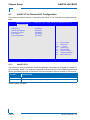
1
AM5030 uEFI BIOS Doc. ID: 1037-1209, Rev. 1.0 August 27, 2010 If it’s embedded, it’s Kontron. PRELIMINARY » User Guide « Preface AM5030 Revision History Publication Title: AM5030 uEFI BIOS User Guide Doc. ID: 1037-1209 Rev. PRELIMINARY 1.0 Brief Description of Changes Date of Issue Initial issue based on the uEFI BIOS version R12 27-Aug-2010 Imprint Kontron Modular Computers GmbH may be contacted via the following: MAILING ADDRESS TELEPHONE AND E-MAIL Kontron Modular Computers GmbH +49 (0) 800-SALESKONTRON Sudetenstraße 7 [email protected] D - 87600 Kaufbeuren Germany For further information about other Kontron products, please visit our Internet web site: www.kontron.com. Disclaimer Copyright © 2010 Kontron AG. All rights reserved. All data is for information purposes only and not guaranteed for legal purposes. Information has been carefully checked and is believed to be accurate; however, no responsibility is assumed for inaccuracies. Kontron and the Kontron logo and all other trademarks or registered trademarks are the property of their respective owners and are recognized. Specifications are subject to change without notice. Page ii ID 1037-1209, Rev. 1.0 AM5030 uEFI BIOS Preface Table of Contents Revision History .........................................................................................................ii Imprint ........................................................................................................................ii Disclaimer ..................................................................................................................ii Table of Contents ...................................................................................................... iii 1. Starting uEFI BIOS Setup .............................................................3 1.1 Main Setup Menu ......................................................................................... 4 2. Main Setup .....................................................................................9 2.1 BIOS Information .......................................................................................... 9 2.2 Memory Information ..................................................................................... 9 2.3 System Language ...................................................................................... 10 2.4 System Date ............................................................................................... 10 2.5 System Time .............................................................................................. 10 2.6 Access Level .............................................................................................. 10 3. Advanced Setup ..........................................................................13 3.1 Trusted Computing ..................................................................................... 14 3.1.1 TPM Configuration ............................................................................. 14 3.1.1.1 TPM Support ............................................................................. 14 3.2 USB Configuration ..................................................................................... 15 3.2.1 USB Configuration ............................................................................. 15 3.2.2 Legacy USB Support ......................................................................... 15 3.2.3 EHCI Hand-Off ................................................................................... 16 3.2.4 USB Transfer Timeout ....................................................................... 16 3.2.5 Device Reset Timeout ....................................................................... 16 3.2.6 Device Power Delay .......................................................................... 17 3.2.7 Mass Storage Devices ....................................................................... 17 3.3 Serial Port Console Redirection ................................................................. 18 3.3.1 COM0 ................................................................................................ 18 ID 1037-1209, Rev. 1.0 Page iii PRELIMINARY 1.2 Navigation .................................................................................................... 5 Preface 3.3.1.1 Console Redirection ..................................................................18 3.3.1.2 Console Redirection Settings ....................................................18 3.3.2 PRELIMINARY COM4 .................................................................................................19 3.3.2.1 Console Redirection ..................................................................19 3.3.2.2 Console Redirection Settings ....................................................19 3.3.3 Serial Port for Out-of-Band Management/Windows EMS ..................19 3.3.3.1 Console Redirection ..................................................................19 3.3.3.2 Out-of-Band Mgmt Port ..............................................................19 3.3.3.3 Data Bits ....................................................................................19 3.3.3.4 Parity ..........................................................................................20 3.3.3.5 Stop Bits .....................................................................................20 3.3.3.6 Terminal Type ............................................................................20 3.3.4 4. AM5030 uEFI BIOS Console Redirection Settings .............................................................21 3.3.4.1 Terminal Type ............................................................................21 3.3.4.2 Bits per second ..........................................................................21 3.3.4.3 Data Bits ....................................................................................22 3.3.4.4 Parity ..........................................................................................22 3.3.4.5 Stop Bits .....................................................................................22 3.3.4.6 Flow Control ...............................................................................22 3.3.4.7 Resolution 100x31 .....................................................................22 3.3.4.8 Legacy OS Redirection ..............................................................22 Chipset Setup ............................................................................. 25 4.1 Intel® VT for Directed I/O Configuration .....................................................26 4.1.1 Intel(R) VT-d .......................................................................................26 4.1.2 Interrupt Remapping ..........................................................................27 4.1.3 Coherency Support ............................................................................27 4.1.4 ATS Support .......................................................................................27 4.1.5 Pass-through DMA .............................................................................28 4.2 NorthBridge Configuration ..........................................................................29 5. Boot Setup .................................................................................. 33 5.1 Boot Configuration ......................................................................................33 Page iv ID 1037-1209, Rev. 1.0 AM5030 uEFI BIOS Preface 5.1.1 Quiet Boot .......................................................................................... 33 5.1.2 Fast Boot ........................................................................................... 34 5.1.3 Setup Prompt Timeout ....................................................................... 34 5.1.4 Bootup NumLock State ...................................................................... 34 5.1.5 CSM16 Module Version ..................................................................... 34 5.1.6 GateA20 Active .................................................................................. 34 5.1.7 Option ROM Messages ..................................................................... 35 5.1.8 Interrupt 19 Capture ........................................................................... 35 6. 5.2.1 Boot Option #1..2 ............................................................................... 36 5.2.2 Hard Drive/Network Device/CD/DVD ROM Drive/etc. ..................... 36 5.2.3 Add New Boot Option ........................................................................ 36 5.2.4 Delete Boot Option ............................................................................ 36 Security Setup .............................................................................39 6.1 Administrator Password ............................................................................. 40 6.2 User Password ........................................................................................... 40 6.3 Remember the Password ........................................................................... 40 7. Save & Exit ...................................................................................43 7.1 Save Changes and Exit .............................................................................. 43 7.2 Discard Changes and Exit .......................................................................... 43 7.3 Save Changes and Reset .......................................................................... 43 7.4 Discard Changes and Reset ...................................................................... 44 7.5 Save Changes (Save Options) ................................................................... 44 7.6 Discard Changes (Save Options) ............................................................... 44 7.7 Restore Defaults (Save Options) ................................................................ 44 7.8 Save as User Defaults (Save Options) ....................................................... 44 7.9 Restore User Defaults (Save Options) ....................................................... 44 7.10 Boot Override ............................................................................................. 44 8. The uEFI Shell ..............................................................................47 ID 1037-1209, Rev. 1.0 Page v PRELIMINARY 5.2 Boot Option Priorities ................................................................................. 36 Preface AM5030 uEFI BIOS 8.1 Introduction, Basic Operation .....................................................................47 8.1.1 Shell Startup .......................................................................................47 8.2 Kontron Shell Commands ...........................................................................48 PRELIMINARY 8.3 uEFI Shell Scripting ....................................................................................62 9. 8.3.1 Startup Scripting .................................................................................62 8.3.2 Create a Startup Script .......................................................................62 8.3.3 Examples of Startup Scripts ...............................................................62 8.3.3.1 Automatic Booting from USB Memory Stick ..............................62 8.3.3.2 Switch On Clock Spreading Prior to Booting from Harddrive ....62 8.3.3.3 Execute Shell Script on Other Harddrive ...................................62 Updating the uEFI BIOS ............................................................. 65 9.1 BIOS Redundancy Strategy ........................................................................65 9.2 Updating Strategy .......................................................................................65 9.3 Fallback Mechanism ...................................................................................65 9.4 Flash Selection by IPMI Command ............................................................65 9.5 Flash Selection by DIP Switch ....................................................................66 9.6 Determining the Active Flash ......................................................................66 Page vi ID 1037-1209, Rev. 1.0 Starting uEFI BIOS Setup Chapter 1 Starting uEFI BIOS Setup ID 1037-1209, Rev. 1.0 Page 1 PRELIMINARY AM5030 uEFI BIOS PRELIMINARY Starting uEFI BIOS Setup AM5030 uEFI BIOS This page has been intentionally left blank. Page 2 ID 1037-1209, Rev. 1.0 AM5030 uEFI BIOS 1. Starting uEFI BIOS Setup Starting uEFI BIOS Setup The AM5030 is provided with a Kontron-customized, pre-installed and configured version of Aptio® (referred to as uEFI BIOS in this manual), AMI’s next generation BIOS firmware based on the Unified Extensible Firmware Interface (uEFI) specification and the Intel® Platform Innovation Framework for EFI. This uEFI BIOS provides a variety of new and enhanced functions specifically tailored to the hardware features of the AM5030. This user guide reflects the uEFI BIOS version R12. To take advantage of these functions, the uEFI BIOS comes with a Setup program which provides quick and easy access to the individual function settings for control or modification of the uEFI BIOS configuration. To start the uEFI BIOS Setup program, follow the steps below: 1. 2. 3. 4. Power on the board. Wait until the first characters appear on the screen (POST messages or splash screen). Press the <F2> key. If the uEFI BIOS is password-protected, a window such as the one below will appear: Enter Password Enter either the User password or the Administrator password (refer to Chapter 6, Security Setup, for further information), press <RETURN>, and proceed with step 2. 5. A Setup menu with the following token attributes will appear. The currently active menu and the currently active uEFI BIOS Setup item are highlighted in white. ID 1037-1209, Rev. 1.0 Page 3 PRELIMINARY The Setup program allows the accessing of various menus which provide functions or access to sub-menus with more specific functions of their own. The individual menus and the configurable functions are described in this guide. Starting uEFI BIOS Setup 1.1 AM5030 uEFI BIOS Main Setup Menu The Main setup menu is the first screen that appears after starting the Setup program. At the top of this screen and all of the other major screens, there is a setup menu selection bar, which permits access to all of the other major setup menus. These menus are selected via the left-right arrow keys. All setup menu screens have two main frames. The left frame displays all the functions that can be configured. They are displayed in blue. Functions displayed in gray provide information about the status or the operational configuration. The right frame displays the key legend. Above the key legend there is an area reserved for a text message. When a function is selected in the left frame, it is displayed in white. Often a text message will accompany it. PRELIMINARY Aptio Setup Utility - Copyright (C) 2009 American Megatrends, Inc. Main Advanced C h i ps e t Boot Title (black) Read only field (grey) value Setup item (blue) [value] Security Save & Exit Pointer to a subordinate menu : Select Screen : Select Item Enter: +/-: F1: F2: F3 F4: Select Change Opt. General Help Previous Values Optimized Defaults Save ESC: Exit Ve r s i o n 2 . 0 0 . 1 2 0 1 . C o p y r i g h t ( C ) 2 0 0 9 A m e r i c a n M e g a t r e n d s , I n c . Page 4 ID 1037-1209, Rev. 1.0 AM5030 uEFI BIOS 1.2 Starting uEFI BIOS Setup Navigation The AM5030 uEFI BIOS setup program uses a hot key-based navigation system. A hot key legend is located in the right frame on most setup screens.The following table provides information concerning the usage of these hot keys. HOT KEY DESCRIPTION <F1> The <F1> key is used to invoke the General Help window. <F2> The <F2> key is used to restore the previous values. <F3> The <F3> key is used to load the defaults. <F4> The <F4> key is used to save the current settings and exit the uEFI BIOS Setup. Left/Right The Left and Right <Arrow> keys are used to select a major Setup screen. For example: Main Screen, Advanced Screen, Chipset Screen, etc. ↑ ↓ Up/Down The Up and Down <Arrow> keys are used to select a Setup function or a sub-screen. + - Plus/Minus The Plus and Minus <Arrow> keys are used to change the field value of a particular Setup function, for example, system date and time. <ESC> The <ESC> key is used to exit a menu or the uEFI BIOS Setup. Pressing the <ESC> key in a sub-menu causes the next higher menu level to be displayed. When the <ESC> key is pressed in a major Setup menu, the uEFI BIOS Setup is terminated without saving any changes made. <Enter> The <Enter> key is used to execute a command or select a menu. ID 1037-1209, Rev. 1.0 Page 5 PRELIMINARY → ← PRELIMINARY Starting uEFI BIOS Setup AM5030 uEFI BIOS This page has been intentionally left blank. Page 6 ID 1037-1209, Rev. 1.0 Main Setup Chapter 21 Main Setup ID 1037-1209, Rev. 1.0 Page 7 PRELIMINARY AM5030 uEFI BIOS PRELIMINARY Main Setup AM5030 uEFI BIOS This page has been intentionally left blank. Page 8 ID 1037-1209, Rev. 1.0 AM5030 uEFI BIOS 2. Main Setup Main Setup Upon entering the uEFI BIOS Setup program, the Main setup screen is displayed. This screen lists the main setup sub-screens and provides very basic system information as well as functions for setting the system time and date. In addition, the remaining major setup menus can be accessed from this screen. This screen can also be selected from any other major setup screen by using the Main tab. Aptio Setup Utility - Copyright (C) 2009 American Megatrends, Inc. Advanced C h ips e t Bo ot S e c u r it y Sa v e & E xi t BIOS Information BIOS Vendor Core Version Project Version Build Date American Megatrends 4.6.3.7 B3801 12.00 x64 08/17/2010 11:13:10 Memory Information Total Memory 2048 MB (DDR3: 1067 MHz) System Language [English] : Select Screen : Select Item System Date System Time [Thu 08/26/2010] [15:23:54] Access Level Administrator Enter: +/-: F1: F2: F3 F4: Select Change Opt. General Help Previous Values Optimized Defaults Save ESC: Exit Ve r s i o n 2 . 0 0 . 1 2 0 1 . C o p y r i g h t ( C ) 2 0 0 9 A m e r i c a n M e g a t r e n d s , I n c . 2.1 BIOS Information This function provides display-only information concerning the uEFI BIOS. 2.2 Memory Information This function provides display-only information concerning the system memory. ID 1037-1209, Rev. 1.0 Page 9 PRELIMINARY Main Main Setup 2.3 AM5030 uEFI BIOS System Language SETTING DESCRIPTION English Use this function to select the system language. Currently, only English is supported. 2.4 System Date SETTING DESCRIPTION <MM/DD/YYYY> Use this function to change the system date. PRELIMINARY Select System Date using the Up and Down <Arrow> keys. Enter the new values through the keyboard. Press the Left and Right <Arrow> keys to move between fields. 2.5 System Time SETTING DESCRIPTION <HH:MM:SS> Use this function to change the system time. Select System Time using the Up and Down <Arrow> keys. Enter the new values through the keyboard. Press the Left and Right <Arrow> keys to move between fields. Note: The time is in 24-hour format. For example, 5:30 A.M. appears as 05:30:00, and 5:30 P.M. as 17:30:00. 2.6 Access Level This function provides display-only information concerning the uEFI BIOS Setup accessibility for the current Setup session. Depending on the type of password protection used, one of the following settings is displayed: SETTING DESCRIPTION Administrator This setting indicates that read/write access to all setup options is available. User This setting indicates that only a limited subset of all setup options is modifiable. Note: Page 10 If no password is set, the access setup is Administrator. ID 1037-1209, Rev. 1.0 Advanced Setup Chapter 31 Advanced Setup ID 1037-1209, Rev. 1.0 Page 11 PRELIMINARY AM5030 uEFI BIOS PRELIMINARY Advanced Setup AM5030 uEFI BIOS This page has been intentionally left blank. Page 12 ID 1037-1209, Rev. 1.0 AM5030 uEFI BIOS 3. Advanced Setup Advanced Setup Select the Advanced tab to enter the Advanced Setup screen. This screen lists the advanced configuration sub-screens. Aptio Setup Utility - Copyright (C) 2007 American Megatrends, Inc. Main Advanced C h i ps e t Boot S e c u r it y Save & Exit : Select Screen : Select Item Enter: +/-: F1: F2: F3 F4: Select Change Opt. General Help Previous Values Optimized Defaults Save ESC: Exit Ve r s i o n 1 . 2 3 . 11 0 9 . C o p y r i g h t ( C) 2 0 0 7 A m e r i c a n M e g a t r e n d s , I n c . ID 1037-1209, Rev. 1.0 Page 13 PRELIMINARY Trusted Computing USB Configuration Serial Port Console Redirection Advanced Setup 3.1 AM5030 uEFI BIOS Trusted Computing This screen provides functions for specifying the TPM configuration settings and TPM displaying status information. Aptio Setup Utility - Copyright (C) 2009 American Megatrends, Inc. Advanced TPM Configuration TPM Support [Disable] PRELIMINARY Current TPM Status Information TPM SUPPORT OFF : Select Screen : Select Item Enter: +/-: F1: F2: F3 F4: Select Change Opt. General Help Previous Values Optimized Defaults Save ESC: Exit Ve r s i o n 2 . 0 0 . 1 2 0 1 . C o p y r i g h t ( C ) 2 0 0 9 A m e r i c a n M e g a t r e n d s , I n c . 3.1.1 TPM Configuration 3.1.1.1 TPM Support This function is used to provide the Trusted Platform Module (TPM) functionality to the OS. SETTING DESCRIPTION Disable Use this setting to disable TPM support. If this setting is used, the TPM is not present for the OS, regardless whether the function TPM State is enabled or not. Enable Use this setting to enable TPM support. Default setting: Disable Page 14 ID 1037-1209, Rev. 1.0 AM5030 uEFI BIOS 3.2 Advanced Setup USB Configuration This screen provides information about support for USB devices as well as functions for specifying the USB configuration settings. Aptio Setup Utility - Copyright (C) 2009 American Megatrends, Inc. Advanced USB Configuration Legacy USB Support EHCI Hand-Off [Enabled] [Enabled] USB hardware delays a USB transfer time-out Device reset time-out Device power-up delay [20 sec] [20 sec] [Auto] Mass Storage Devices: USB DISK 26X PMAP [Auto] : Select Screen : Select Item Enter: +/-: F1: F2: F3 F4: Select Change Opt. General Help Previous Values Optimized Defaults Save ESC: Exit Ve r s i o n 2 . 0 0 . 1 2 0 1 . C o p y r i g h t ( C ) 2 0 0 9 A m e r i c a n M e g a t r e n d s , I n c . 3.2.1 USB Configuration This is a display-only function providing general information about the USB devices detected. 3.2.2 Legacy USB Support This function is required for booting from USB devices and for operating systems which do not support USB themselves (mainly DOS and some BootLoaders). SETTING DESCRIPTION Disabled Use this setting to disable legacy USB support. Enabled Use this setting to enable legacy USB support. Auto Use this setting to enable legacy USB support if there are USB devices present. Default setting: Enabled ID 1037-1209, Rev. 1.0 Page 15 PRELIMINARY USB Devices: 1 Drives, 1 Keyboard, 1 Mouse, 3 Hub Advanced Setup 3.2.3 AM5030 uEFI BIOS EHCI Hand-Off This function is used to enable a workaround for operating systems without EHCI Hand-Off support. The EHCI ownership change should be claimed by the EHCI driver. Note: It is recommended to leave this function at the default setting. For operating systems without USB2.0 support this function must be left at the default setting. SETTING DESCRIPTION Disabled Use this setting to disable EHCI Hand-Off support. Enabled Use this setting to enable EHCI Hand-Off support. PRELIMINARY Default setting: Enabled 3.2.4 USB Transfer Timeout This setting selects the timeout in seconds that the USB core will wait for a USB Control, Bulk and Interrupt transfer. SETTING DESCRIPTION 1 sec Use one of these settings to specify how long the USB core will wait for a USB Control, Bulk and Interrupt transfer. 5 sec 10 sec 20 sec Default setting: 20 sec 3.2.5 Device Reset Timeout This setting selects the timeout in seconds that the USB core will wait for a USB storage device to become ready after start unit command. SETTING DESCRIPTION 10 sec Use one of these settings to specify how long the USB core will wait for a USB mass storage device to become ready after the start unit command. 20 sec 30 sec 40 sec Default setting: 20 sec Page 16 ID 1037-1209, Rev. 1.0 AM5030 uEFI BIOS 3.2.6 Advanced Setup Device Power Delay SETTING DESCRIPTION Auto Use this setting to automatically select the maximum time the device will take before it properly reports itself to the host controller. The default value for a root port is 100 ms. For a hub port, the delay is taken from the hub descriptor. Manual Use this setting to manually select the maximum time the device will take before it properly reports itself to the host controller. The delay range is 1..40 seconds in one second increments. Default setting: Auto Mass Storage Devices This function shows a list of connected USB mass storage devices and allows the user to select how the respective device is to be treated. ID 1037-1209, Rev. 1.0 Page 17 PRELIMINARY 3.2.7 Advanced Setup 3.3 AM5030 uEFI BIOS Serial Port Console Redirection This screen provides information about functions for specifying the Serial Port Console Redirection configuration settings. Console redirection can be used to remotely operate system settings and the EFI console. Aptio Setup Utility - Copyright (C) 2009 American Megatrends, Inc. Advanced COM0 Console Redirection Console Redirection Settings [Enabled] PRELIMINARY COM4 (PCI Dev0, Func0) (Disabled) Console Redirection [Port Is Disabled] Serial Port for Out-of-Band Management/ Windows Emergency Management Services (EMS) Console Redirection [Disabled] Out-of-Band Mgmt Port [COM0] Data Bits 8 Parity None Stop Bits 1 Terminal Type [VT-UTF8] : Select Screen : Select Item Enter: +/-: F1: F2: F3 F4: Select Change Opt. General Help Previous Values Optimized Defaults Save ESC: Exit Ve r s i o n 2 . 0 0 . 1 2 0 1 . C o p y r i g h t ( C ) 2 0 0 9 A m e r i c a n M e g a t r e n d s , I n c . 3.3.1 COM0 The COM0 port (serial port 0) corresponds to the serial port on the front panel of the AM5030. 3.3.1.1 Console Redirection SETTING DESCRIPTION Disabled Use this setting to disable console redirection for the serial port 0. Enabled Use this setting to enable console redirection for the serial port 0. Default setting: Enabled 3.3.1.2 Console Redirection Settings For information about this function, refer to Chapter 3.4.4 in this manual. Page 18 ID 1037-1209, Rev. 1.0 AM5030 uEFI BIOS 3.3.2 Advanced Setup COM4 COM4 is available only if the MicroTCA system provides a serial port via PCI Express. 3.3.2.1 Console Redirection SETTING DESCRIPTION Disabled Use this setting to disable console redirection for a PCIe serial port. Enabled Use this setting to enable console redirection for a PCIe serial port. Default setting: Enabled 3.3.2.2 Console Redirection Settings 3.3.3 Serial Port for Out-of-Band Management/Windows Emergency Management Services (EMS) The following functions control the presence and content of the ACPI serial port redirection table (SPCR). This table is mainly used by the Windows server variants to provide Windows Emergency Management Services (EMS). This functionality is totally independent from serial redirection of other console output. 3.3.3.1 Console Redirection SETTING DESCRIPTION Disabled Use this setting to prevent the system from adding the SPCR table to the ACPI tables. Enabled Use this setting to add the SPCR table to the ACPI tables. The OS can further use the information provided for serial redirection services. Default setting: Disabled 3.3.3.2 Out-of-Band Mgmt Port This function is used to select the serial port intended for use with Out-of-Band Management. This functionality is independent from serial redirection of other console output. SETTING DESCRIPTION COM0 Use this setting to specify that the serial port 0 is to be used with Out-of-Band Management. COM4 Use this setting to specify that a PCIe serial port is to be used with Out-of-Band Management. Default setting: COM0 3.3.3.3 Data Bits This is a display-only function providing information about the frame width for the Out-of-Band Management. ID 1037-1209, Rev. 1.0 Page 19 PRELIMINARY For information about this function, refer to Chapter 3.4.4 in this manual. Advanced Setup 3.3.3.4 AM5030 uEFI BIOS Parity This is a display-only function providing information about the parity for Out-of-Band Management. 3.3.3.5 Stop Bits This is a display-only function providing information about the number of stop bits for Out-ofBand Management. 3.3.3.6 Terminal Type SETTING DESCRIPTION VT100 Use one of these settings to select the terminal type for out-of-band management. PRELIMINARY VT100+ VT-UTF8 ANSI Default setting: VT-UTF8 Page 20 ID 1037-1209, Rev. 1.0 AM5030 uEFI BIOS 3.3.4 Advanced Setup Console Redirection Settings This screen provides information about functions for specifying the Console Redirection configuration settings for the serial port 0 and a PCIe serial port. Each serial port can be independently configured. Aptio Setup Utility - Copyright (C) 2009 American Megatrends, Inc. Main Boot S e c u r it y S a v e & E x it Terminal Type Bits per second Data Bits Parity Stop Bits Flow Control Resolution 100x31 Legacy OS Redirection [ANSI] [115200] [8] [None] [1] [None] [Disabled] [80x24] : Select Screen : Select Item Enter: +/-: F1: F2: F3 F4: Select Change Opt. General Help Previous Values Optimized Defaults Save ESC: Exit Ve r s i o n 2 . 0 0 . 1 2 0 1 . C o p y r i g h t ( C ) 2 0 0 9 A m e r i c a n M e g a t r e n d s , I n c . 3.3.4.1 Terminal Type SETTING DESCRIPTION VT100 Use one of these settings to select the terminal type to be emulated. VT100+ VT-UTF8 ANSI Default setting: ANSI 3.3.4.2 Bits per second SETTING DESCRIPTION 9600 Use one of these settings to select the baud rate of the serial port. 19200 57600 115200 Default setting: 115200 ID 1037-1209, Rev. 1.0 Page 21 PRELIMINARY COM0 Console Redirection Settings Advanced Setup 3.3.4.3 AM5030 uEFI BIOS Data Bits SETTING DESCRIPTION 7 Use one of these settings to specify the number of data bits per frame. 8 Default setting: 8 3.3.4.4 Parity SETTING DESCRIPTION None Use one of these settings to select the parity for the serial port. Even PRELIMINARY Odd Mark Space Default setting: None 3.3.4.5 Stop Bits SETTING DESCRIPTION 1 Use one of these settings to specify the number of stop bits for the serial port. 2 Default setting: 1 3.3.4.6 Flow Control SETTING DESCRIPTION None Use one of these settings to specify the type of flow control to be used for this serial port. Hardware RTS/CTS Default setting: None 3.3.4.7 Resolution 100x31 SETTING DESCRIPTION Disabled Use this setting the disable extended terminal resolution. Enabled Use this setting the enable extended terminal resolution. Default setting: Disabled 3.3.4.8 Legacy OS Redirection SETTING DESCRIPTION 80x24 Use one of these settings to select the number of rows and columns for legacy OSredirection. 80x25 Default setting: 80x24 Page 22 ID 1037-1209, Rev. 1.0 Chipset Setup Chapter 41 Chipset Setup ID 1037-1209, Rev. 1.0 Page 23 PRELIMINARY AM5030 uEFI BIOS PRELIMINARY Chipset Setup AM5030 uEFI BIOS This page has been intentionally left blank. Page 24 ID 1037-1209, Rev. 1.0 AM5030 uEFI BIOS 4. Chipset Setup Chipset Setup Select the Chipset tab to enter the Chipset Setup screen. This screen indicates the NorthBridge sub-screen. Aptio Setup Utility - Copyright (C) 2007 American Megatrends, Inc. Main Advanced C h i ps e t Boot S e c u r it y Save & Exit : Select Screen : Select Item Enter: +/-: F1: F2: F3 F4: Select Change Opt. General Help Previous Values Optimized Defaults Save ESC: Exit Ve r s i o n 1 . 2 3 . 11 0 9 . C o p y r i g h t ( C) 2 0 0 7 A m e r i c a n M e g a t r e n d s , I n c . ID 1037-1209, Rev. 1.0 Page 25 PRELIMINARY Intel(R) VT for Directed I/O Configuration North Bridge Chipset Setup 4.1 AM5030 uEFI BIOS Intel® VT for Directed I/O Configuration This screen provides functions for specifying the Intel® VT for Directed I/O configuration settings. Aptio Setup Utility - Copyright (C) 2009 American Megatrends, Inc. Advanced PRELIMINARY Intel(R) VT-d Interrupt Remapping Coherency Support ATS Support Pass-through DMA [Enabled] [Enabled] [Disabled] [Enabled] [Enabled] : Select Screen : Select Item Enter: +/-: F1: F2: F3 F4: Select Change Opt. General Help Previous Values Optimized Defaults Save ESC: Exit Ve r s i o n 2 . 0 0 . 1 2 0 1 . C o p y r i g h t ( C ) 2 0 0 9 A m e r i c a n M e g a t r e n d s , I n c . 4.1.1 Intel(R) VT-d This function is used to enable the Intel® Virtualization Technology for Directed I/O (Intel® VTd) functionality. Intel® VT-d supports remapping of direct memory access (DMA) transfers and device generated interrupts on hardware level, which helps to improve isolation of I/O devices. SETTING DESCRIPTION Disable Use this setting to disable Intel(R) VT-d support. Enable Use this setting to enable Intel(R) VT-d support. Default setting: Disabled Page 26 ID 1037-1209, Rev. 1.0 AM5030 uEFI BIOS 4.1.2 Chipset Setup Interrupt Remapping This function allows for reductions in interrupt virtualization overhead for assigned devices. Interrupt requests specify a requester ID and an interrupt ID, and remap hardware transforms these requests to a physical interrupt using a software-programmed Interrupt Remap Table structure in memory. Note: This function is available only when the function Intel(R) VT-d is set to Enabled. SETTING DESCRIPTION Disable Use this setting to disable Interrupt Remapping. Enable Use this setting to enable Interrupt Remapping. 4.1.3 Coherency Support This function is used to indicate to the hardware to either snoop or not snoop the DMA / Interrupt table structures in memory (root/context/pd/pt/irt). Note: This function is available only when the function Intel(R) VT-d is set to Enabled. SETTING DESCRIPTION Disable Use this setting to disable Coherency Support. Enable Use this setting to enable Coherency Support. Default setting: Disabled 4.1.4 ATS Support This function is used for keeping VT-D I/O TLB and translation cache in sync from allowed devices. To facilitate scaling of address translation caches, PCI Express protocol extensions (referred to as Address Translation Services) are being standardized by the PCI Special Interest Group (PCI-SIG). ATS consists of a set of PCI transactions that allow the optimization of VT-d address translations These extensions enable I/O devices to request translations from the root complex and for the root complex to return responses for each translation request. Note: This function is available only when the function Intel(R) VT-d is set to Enabled. SETTING DESCRIPTION Disable Use this setting to disable ATS Support. Enable Use this setting to enable ATS Support. Default setting: Enabled ID 1037-1209, Rev. 1.0 Page 27 PRELIMINARY Default setting: Enabled Chipset Setup 4.1.5 AM5030 uEFI BIOS Pass-through DMA This function is used to enable/disable VT-d engine pass-through DMA support. DMA request with untranslated addresses are processed as pass-through and will cause a DMA draining. Note: This function is available only when the function Intel(R) VT-d is set to Enabled. SETTING DESCRIPTION Disable Use this setting to disable Pass-through DMA support. Enable Use this setting to enable Pass-through DMA support. PRELIMINARY Default setting: Enabled Page 28 ID 1037-1209, Rev. 1.0 AM5030 uEFI BIOS 4.2 Chipset Setup NorthBridge Configuration This screen provides display-only information concerning the memory, which is integrated in the Intel® Xeon® LC5518 processor. Aptio Setup Utility - Copyright (C) 2007 American Megatrends, Inc. Main Advanced Processor SKU: C h i ps e t Boot S e c u r it y Save & Exit 7 Total Memory Current Memory Mode Current Memory Speed Mirroring Sparing 2048 MB (DDR3) Independent 1067 MHz Not Possible Not Possible : Select Screen : Select Item Enter: +/-: F1: F2: F3 F4: Select Change Opt. General Help Previous Values Optimized Defaults Save ESC: Exit Ve r s i o n 1 . 2 3 . 11 0 9 . C o p y r i g h t ( C) 2 0 0 7 A m e r i c a n M e g a t r e n d s , I n c . ID 1037-1209, Rev. 1.0 Page 29 PRELIMINARY Memory Information PRELIMINARY Chipset Setup AM5030 uEFI BIOS This page has been intentionally left blank. Page 30 ID 1037-1209, Rev. 1.0 Boot Setup Chapter 51 Boot Setup ID 1037-1209, Rev. 1.0 Page 31 PRELIMINARY AM5030 uEFI BIOS PRELIMINARY Boot Setup AM5030 uEFI BIOS This page has been intentionally left blank. Page 32 ID 1037-1209, Rev. 1.0 AM5030 uEFI BIOS 5. Boot Setup Boot Setup Select the Boot tab to enter the Boot Setup screen. This screen lists the sub-screens for boot configuration and boot device priority. Aptio Setup Utility - Copyright (C) 2009 American Megatrends, Inc. Advanced C h ips e t Bo ot S e c u r it y Boot Configuration Quiet Boot Fast Boot Setup Prompt Timeout [Disabled] [Disabled] 1 Bootup NumLock State [On] CSM16 Module Version 07.63 GateA20 Active Option ROM Messages Interrupt 19 Capture [Upon Request] [Force BIOS] [Disabled] Boot Option Priorities Boot Option #1 Boot Option #2 [Built-in EFI Shell] [SanDisk uSSD 5000 ...] Hard Drive BBS Priorities Network Device BBS Priorities CD/DVD ROM Drive BBS Priorities Floppy Drive BBS Priorities BEV Device BBS Priorities Add New Boot Option Delete Boot Option Sa v e & E xi t : Select Screen : Select Item Enter: +/-: F1: F2: F3 F4: Select Change Opt. General Help Previous Values Optimized Defaults Save ESC: Exit Ve r s i o n 2 . 0 0 . 1 2 0 1 . C o p y r i g h t ( C ) 2 0 0 9 A m e r i c a n M e g a t r e n d s , I n c . 5.1 Boot Configuration 5.1.1 Quiet Boot This function is used to display either POST output messages or a splash screen during boot-up. SETTING DESCRIPTION Disabled Use this setting to display POST output messages during boot-up. Enabled Use this setting to display a splash screen during boot-up. Default setting: Disabled ID 1037-1209, Rev. 1.0 Page 33 PRELIMINARY Main Boot Setup 5.1.2 AM5030 uEFI BIOS Fast Boot This function is used to enable or disable boot with initialization of a minimal set of devices required to launch active boot option.. SETTING DESCRIPTION Disabled Use this setting to disable fast boot. Enabled Use this setting to enable fast boot. Default setting: Disabled 5.1.3 Setup Prompt Timeout PRELIMINARY This integer function is used to set an additional time the POST should wait for the operator to press the key to enter setup. The time is entered in seconds. SETTING DESCRIPTION 1 Use one of these settings to specify the setup prompt timeout. .. . 65535 Default setting: 1 5.1.4 Bootup NumLock State This function is used to set the state of the keyboard’s numlock function after POST. SETTING DESCRIPTION On Use this setting to switch on the keyboard’s numlock function after POST. Off Use this setting to switch off the keyboard’s numlock function after POST. Default setting: On 5.1.5 CSM16 Module Version This function provides display-only information concerning the CSM Module and is intended for internal use only. 5.1.6 GateA20 Active This function is used to enable or disable GateA20. SETTING DESCRIPTION Upon Request Use this setting to disable GA20 in the uEFI BIOS. Always Use this setting to prevent the system from disabling GA20. Default setting: Upon Request Page 34 ID 1037-1209, Rev. 1.0 AM5030 uEFI BIOS 5.1.7 Boot Setup Option ROM Messages This function is used to control the messages of the loaded PCI option ROMs. SETTING DESCRIPTION Force BIOS Use this setting to force to a BIOS-compatible output. This will show the option ROM messages. Keep Current Use this setting to keep the current video mode. This will suppress option ROM messages. Option ROMs requiring interactive inputs may not work properly in this mode. Default setting: Force BIOS Interrupt 19 Capture This function is used to specify if legacy PCI option ROMs are allowed to capture software interrupt 19h. SETTING DESCRIPTION Disabled Use this setting to prevent legacy PCI option ROMs from capturing software interrupt 19h. Enabled Use this setting to allow legacy PCI option ROMs to capture software interrupt 19h. Default setting: Disabled ID 1037-1209, Rev. 1.0 Page 35 PRELIMINARY 5.1.8 Boot Setup 5.2 Boot Option Priorities 5.2.1 Boot Option #1..2 AM5030 uEFI BIOS These functions are used to form the boot order and are dynamically generated. They represent either a legacy BBS (BIOS Boot Specification) class of devices or a native EFI boot entry. Press Return on each option to select the BBS class / EFI boot entry desired. 5.2.2 Hard Drive/Network Device/CD/DVD ROM Drive/Floppy Drive/ BEV Device BBS Priorities PRELIMINARY These functions lead to sub-menus that allow configuring the boot order for a specific device class. These options are only visible if at least one device for this class is present. These functions are dynamically generated. 5.2.3 Add New Boot Option This function is used to create a native uEFI boot option. Refer to the user manual for the respective native uEFI operating system further information about creating a boot option. 5.2.4 Delete Boot Option This function is used to delete a native uEFI boot option. Refer to the user manual for the respective native uEFI operating system further information about deleting a boot option. Note: Page 36 Do not delete the “Built-in EFI Shell” boot option as this would remove the uEFI Shell from the boot order. In case the uEFI Shell got removed, use “Save & Exit” / “Boot Override” / “Built-in EFI Shell” to recover. ID 1037-1209, Rev. 1.0 Security Setup Chapter 61 Security Setup ID 1037-1209, Rev. 1.0 Page 37 PRELIMINARY AM5030 uEFI BIOS PRELIMINARY Security Setup AM5030 uEFI BIOS This page has been intentionally left blank. Page 38 ID 1037-1209, Rev. 1.0 AM5030 uEFI BIOS 6. Security Setup Security Setup Select the Security tab to enter the Security Setup screen. This screen provides information about the passwords and functions for specifying the security settings. Aptio Setup Utility - Copyright (C) 2009 American Megatrends, Inc. Main Advanced C h ips e t Bo ot S e c u r it y Sa v e & E xi t If ONLY the Administrator’s password is set, then this only limits access to Setup and is only asked for when entering Setup. If ONLY the User’s password is set, then this is a power on password and must be entered to boot or enter Setup. In Setup the User will have Administrator rights. Administrator Password User Password : Select Screen : Select Item Enter: +/-: F1: F2: F3 F4: Select Change Opt. General Help Previous Values Optimized Defaults Save ESC: Exit Ve r s i o n 2 . 0 0 . 1 2 0 1 . C o p y r i g h t ( C ) 2 0 0 9 A m e r i c a n M e g a t r e n d s , I n c . The following modes of security are provided:. SETTING DESCRIPTION No password is set Booting the system as well as entering the Setup is unsecured. Only Administrator password is set Booting the system is unsecured. Only User password is set The password is required for booting the system as well as for entering the Setup menu. On every startup, the user will be asked for the password. Both User and Administrator passwords are set Booting the system is unsecured. For entering the Setup, the Administrator password is required. For entering the Setup, a password is required. If the User password is entered here, most of the Setup entries are read only; only entries related to the boot sequence can be modified. Entering the Administrator password provides full access to all Setup entries. ID 1037-1209, Rev. 1.0 Page 39 PRELIMINARY Password Description Security Setup 6.1 AM5030 uEFI BIOS Administrator Password This function is used to set, change or delete the Administrator password. If there is already a password installed, the system asks for this first. To clear a password, simply enter nothing and acknowledge by pressing Return. To set a password, enter it twice and acknowledge by pressing Return. Note: The password is case sensitive. 6.2 User Password PRELIMINARY This function is used to set, change or delete the User password. If there is already a password installed, the system asks for this first. To clear a password, simply enter nothing and acknowledge by pressing Return. To set a password, enter it twice and acknowledge by pressing Return. Note: The password is case sensitive. 6.3 Remember the Password It is highly recommended to keep a record of all passwords in a safe place. Forgotten passwords may lead to being completely locked out of the system. Booting may not be possible, and in worst case the uEFI BIOS Setup program will also not be accessible. If the system cannot be booted because neither the User password nor the Administrator password are known, refer to Chapter 4.1 in the AM5030 User Guide for information about clearing the uEFI BIOS settings, or contact Kontron for further assistance. Page 40 ID 1037-1209, Rev. 1.0 Save & Exit Chapter 71 Save & Exit ID 1037-1209, Rev. 1.0 Page 41 PRELIMINARY AM5030 uEFI BIOS PRELIMINARY Save & Exit AM5030 uEFI BIOS This page has been intentionally left blank. Page 42 ID 1037-1209, Rev. 1.0 AM5030 uEFI BIOS 7. Save & Exit Save & Exit Select the Save & Exit tab to enter the Save & Exit menu screen. This screen provides functions for handling changes made to the uEFI BIOS settings and the exiting of the Setup program. Aptio Setup Utility - Copyright (C) 2009 American Megatrends, Inc. Main Advanced C h ips e t Bo ot S e c u r it y Sa v e & E xi t Save Options Save Changes Discard Changes : Select Screen : Select Item Restore Defaults Save as User Defaults Restore User Defaults Boot Override Built-in EFI Shell SanDisk uSSD 5000 0.1 Enter: +/-: F1: F2: F3 F4: Select Change Opt. General Help Previous Values Optimized Defaults Save ESC: Exit Ve r s i o n 2 . 0 0 . 1 2 0 1 . C o p y r i g h t ( C ) 2 0 0 9 A m e r i c a n M e g a t r e n d s , I n c . 7.1 Save Changes and Exit This function is used to save all changes made within the Setup to Flash. This function continues the boot process as long as no option was altered that requires a reboot. Note: The Setup will ask for confirmation prior to executing this command. 7.2 Discard Changes and Exit This function is used to discard all changes made within the Setup. This function continues the boot process. Note: The Setup will ask for confirmation prior to executing this command. 7.3 Save Changes and Reset This function is used to save all changes made within the Setup to Flash. This function performs a reboot afterwards. Note: The Setup will ask for confirmation prior to executing this command. ID 1037-1209, Rev. 1.0 Page 43 PRELIMINARY Save Changes and Exit Discard Changes and Exit Save Changes and Reset Discard Changes and Reset Save & Exit 7.4 AM5030 uEFI BIOS Discard Changes and Reset This function is used to discard all changes made within the Setup. This function performs a reboot afterwards. Note: The Setup will ask for confirmation prior to executing this command. 7.5 Save Changes (Save Options) PRELIMINARY This function is used to save all changes made within the Setup to Flash. This function returns to Setup. Note: The Setup will ask for confirmation prior to executing this command. 7.6 Discard Changes (Save Options) This function is used to discard all changes made within the Setup. This function returns to Setup. Note: The Setup will ask for confirmation prior to executing this command. 7.7 Restore Defaults (Save Options) This function is used to restore all tokens to factory default. Note: The Setup will ask for confirmation prior to executing this command. 7.8 Save as User Defaults (Save Options) This function is used to save all current settings as user default. The current setup state can later be restored using Restore User Defaults. Note: The Setup will ask for confirmation prior to executing this command. 7.9 Restore User Defaults (Save Options) This function is used to restore all tokens to settings previously stored by Save as User Defaults. Note: The Setup will ask for confirmation prior to executing this command. 7.10 Boot Override This group of functions includes a list of tokens, each of them corresponding to one device within the boot order. Select a drive to immediately boot that device regardless of the current boot order. If booting to EFI Shell this way, an exit from the shell returns to Setup. Page 44 ID 1037-1209, Rev. 1.0 The uEFI Shell Chapter 81 The uEFI Shell ID 1037-1209, Rev. 1.0 Page 45 PRELIMINARY AM5030 uEFI BIOS PRELIMINARY The uEFI Shell AM5030 uEFI BIOS This page has been intentionally left blank. Page 46 ID 1037-1209, Rev. 1.0 AM5030 uEFI BIOS 8. The uEFI Shell The uEFI Shell The Kontron uEFI BIOS features a built-in and enhanced version of the uEFI Shell. For a detailed description of the available standard shell scripting refer to the EFI Shell User’s Guide. For a detailed description of the available standard shell commands, refer to the Shell Command Manual 1.0. Both documents can be downloaded from the EFI and Framework Open Source Community homepage (https://efi-shell.tianocore.org) under the “Documents and Files” section. Please note that not all shell commands described in the Shell Command Manual 1.0 are provided by the Kontron uEFI BIOS. Introduction, Basic Operation The uEFI Shell forms an entry into the uEFI boot order and is the first boot option by default. It is simply started by putting the uEFI Shell first in boot and running the board as usual. 8.1.1 Shell Startup If the shell is executed, it displays its signon message followed by a list of detected devices. The output produced by the device mapping table can vary depending on the board’s configuration. EFI Shell version 2.00 [4.637] Current running mode 1.1.2 Device mapping table fs0 :Removable HardDisk - Alias hd33b0b0b blk0 Acpi(PNP0A03,0)/Pci(1D|7)/Usb(1, 0)/Usb(1, 0)/HD(Part1,Sig17731773) fs1 :Removable BlockDevice - Alias f33b0c0 blk1 Acpi(PNP0A03,0)/Pci(1D|7)/Usb(1, 0)/Usb(2, 0) blk0 :Removable HardDisk - Alias hd33b0b0b fs0 Acpi(PNP0A03,0)/Pci(1D|7)/Usb(1, 0)/Usb(1, 0)/HD(Part1,Sig17731773) blk1 :Removable BlockDevice - Alias f33b0c0 fs1 Acpi(PNP0A03,0)/Pci(1D|7)/Usb(1, 0)/Usb(2, 0) blk2 :HardDisk - Alias (null) Acpi(PNP0A03,0)/Pci(1F|2)/Ata(Primary,Master)/HD(Part1,SigC811D18D) blk3 :BlockDevice - Alias (null) Acpi(PNP0A03,0)/Pci(1F|2)/Ata(Primary,Master) blk4 :Removable BlockDevice - Alias (null) Acpi(PNP0A03,0)/Pci(1D|7)/Usb(1, 0)/Usb(1, 0) Press the ESC key within 5 seconds to skip startup.nsh, and any other key to continue. If the ESC key is pressed before the 5-second timeout has elapsed, the shell prompt is shown: Shell> ID 1037-1209, Rev. 1.0 Page 47 PRELIMINARY 8.1 The uEFI Shell 8.2 AM5030 uEFI BIOS Kontron Shell Commands The Kontron uEFI implementation provides the following additional commands related to the specific HW features of the Kontron system: PRELIMINARY • • • • • • • • • • kboardconfig kboardinfo kboot kbootnsh kclearnvram kclsp kipmi kmkramdisk kpassword kwdt The following tables provide information concerning these Kontron-specific commands. The command response values indicated can vary depending on the board’s configuration. Page 48 ID 1037-1209, Rev. 1.0 AM5030 uEFI BIOS The uEFI Shell kboardconfig FUNCTION: SYNTAX: Configure the non-volatile board settings kboardconfig kboardconfig [-?|<device>|<setting>] where: ? <device> <setting> USAGE: The kboardconfig command enables the PXE feature or sets the front/ rear I/O configuration of the dedicated device. Show all possible configurations COMMAND / RESPONSE: Shell> kboardconfig Control nonvolatile board settings Example: kboardconfig hyperThreading: Enable Hyper Threading technology (disabled [enabled]) pxe: config ([disabled] all gbe_a gbe_b amc_a amc_b xaui_a xaui_b) sataMode: SATA controller config (disabled [ide] ahci raid) amcport_2: SATA Port config ([e-keying] forced_on) amcport_3: SATA Port config ([e-keying] forced_on) amcport_12: SATA Port config ([e-keying] forced_on) amcport_13: SATA Port config ([e-keying] forced_on) storageOrom: Launch Storage PCI OpROM (disabled [enabled]) vga: VGA Port Configuration (disabled [enabled]) bootvideo: Select preferred boot video device (amc [onboard]) wr_prot_eeprom: System EEprom write protection ([disabled] enabled) wr_prot_sata: Onboard Sata flash write protection ([disabled] enabled) wr_prot_spi: EFI spi flash write protection ([disabled] enabled) Show allowed settings e.g. for “bootvideo”: Shell> kboardconfig bootvideo bootvideo: Select preferred boot video device bootvideo == onboard Allowed options: amc, onboard SETTINGS hyperThreading: Enable/Disable Hyper-Threading Technology ID 1037-1209, Rev. 1.0 Page 49 PRELIMINARY DESCRIPTION: Show online help Specify device from list Select configuration type The uEFI Shell AM5030 uEFI BIOS kboardconfig SETTINGS: pxe: Select PXE boot network adapter disabled: No PXE boot available [all]: Try all Ethernet devices round robin for PXE boot gbe_a: Try only front port a for PXE boot gbe_b: Try only front port b for PXE boot amc_a: Try only AMC port a for PXE boot amc_b: Try only AMC port b for PXE boot xaui_a: Try only XAUI port a for PXE boot xaui_b: Try only XAUI port b for PXE boot PRELIMINARY SATAMode: Determines how SATA controllers operate disabled: Disable the SATA ports [ide]: SATA ports operate as two IDE controllers ahci: SATA ports operate as one 6-port AHCI controller raid: SATA ports form a RAID device amcport_2: Select SATA port configuration on AMC port 2 [e-keying]: Enable/disable AMC port 2 via e-keying forced_on: AMC port 2 is always enabled amcport_3: Select SATA port configuration on AMC port 3 [e-keying]: Enable/disable AMC port 3 via e-keying forced_on: AMC port 3 is always enabled amcport_12: Select SATA port configuration on AMC port 12 [e-keying]: Enable/disable AMC port 12 via e-keying forced_on: AMC port 12 is always enabled Note: For non-standard MicroTCA racks, this function must be set to forced_on in order to be able to use the SATA ports. amcport_13: Select SATA port configuration on AMC port 13 [e-keying]: Enable/disable AMC port 13 via e-keying forced_on: AMC port 13 is always enabled Note: For non-standard MicroTCA racks, this function must be set to forced_on in order to be able to use the SATA ports. storageOrom: Launch Storage PCI Option ROMs disabled: Do not launch storage PCI option ROMs. This includes the onboard RAID option ROM. [enabled]: Launch storage option ROMs, if present Page 50 ID 1037-1209, Rev. 1.0 AM5030 uEFI BIOS The uEFI Shell kboardconfig SETTINGS: vga: VGA port configuration disabled: Disable VGA port configuration [enabled]: Enable VGA port configuration bootvideo: Select preferred boot video device amc: Use video on the AMC port onboard: Use onboard graphics wr_prot_sata: Onboard SATA Flash write protection [disabled]: Do not write protect the onboard SATA Flash Warning! The SATA Flash module is factory-configured to disabled. Do not change this setting. enabled: This setting is reserved for factory purposes. Do not use this setting. wr_prot_spi: EFI SPI Flash write protection [disabled]: Do not write protect the EFI SPI Flash enabled: The EFI SPI Flash is write-protected after POST ID 1037-1209, Rev. 1.0 Page 51 PRELIMINARY wr_prot_eeprom: System EEPROM write protection [disabled]: Do not write protect the system EEPROM enabled: System EEPROM is write-protected after POST The uEFI Shell AM5030 uEFI BIOS kboardinfo FUNCTION: SYNTAX: DESCRIPTION: USAGE: Show board identification data kboardinfo The kboardinfo command shows a summary of board-specific identification data. It is especially useful for support queries because it contains this data in a concentrated form. Show board identification data COMMAND / RESPONSE: PRELIMINARY Shell> kboardinfo KOMaOEMF rev.: Board ID: Hardware rev.: Logic rev.: Boot flash: Geographic address: Material number: Hardware index: Serial number: EFI article name: EFI material number: EFI index: EFI build time: EFI build date: NorthBridge rev.: SouthBridge rev.: Microcode: CPU ID: CPU Branding: Page 52 3 0xB380 0x0 0x1 Boot flash 0 3 SK-EFI-B3801 1036-5132 12, standard 11:13:10 08/17/2010 0x10 0x6 0xFFFF0002 0x106E4 Intel(R) Xeon(R)CPU C5518 @ 1.73 GHz ID 1037-1209, Rev. 1.0 AM5030 uEFI BIOS The uEFI Shell SETTINGS: KOMaOEMF rev.: Board ID: Hardware rev.: Logic rev.: Boot flash: Geographic Address: Material number: Hardware index: Serial number: EFI article name: EFI material number: EFI index: EFI build time: EFI build date: NorthBridge rev.: SouthBridge rev.: Microcode: CPU ID: CPU Branding: ID 1037-1209, Rev. 1.0 Revision of KOMaOEMF protocol Kontron board identification value (should be 0xB380 for the AM5030) Hardware revision of this board Logic revision of this board Current boot Flash: either “Boot flash 0” or “Boot flash 1” Geographic address of the MicroTCA backplane slot the board is currently plugged into Kontron hardware reference number Kontron hardware index This board’s unique serial number Kontron uEFI reference name Kontron uEFI reference number Version of this uEFI BIOS Build time of this uEFI BIOS Build date of this uEFI BIOS Chip revision of the NorthBridge Chip revision of the SouthBridge (Intel ® 3420) Currently loaded microcode CPUID CPU identification string Page 53 PRELIMINARY kboardinfo The uEFI Shell AM5030 uEFI BIOS kboot FUNCTION: SYNTAX: Boot a legacy OS Not to be used for uEFI BootLoaders! kboot [-?|-d|-p|-p <path>|-n <name>|-t <type>] PRELIMINARY where: ? -d -p <path> -n <name> -t <type> DESCRIPTION: USAGE: Show online help Boot default order Specify the path to the device to boot from Specify the device name to boot from Specify the device type to boot from Available types are: floppy harddrive cdrom network usb-floppy usb-harddrive usb-cdrom The kboot command boots a legacy OS. Boot device can be selected in a very flexible way. If the requested device is not present, boot returns to shell. The kboot command cannot boot native uEFI operating systems. But since these are bootable from shell by calling their bootloader, this is not necessary either. If a requested device is present but not bootable, uEFI continues to boot with the next bootable device in the boot order. Show all connected devices: COMMAND / RESPONSE: fs0:\> kboot ____BBS_TABLE____ 00002 network “IBA GE Slot 0100 v1300” 00003 network “IBA GE Slot 0101 v1300” 00004 network “IBA GE Slot 0200 v1300” 00005 network “IBA GE Slot 0201 v1300” 00002 usb-harddrive “SanDisk uSSD 5000 0.1” Device path: Acpi(PNP0A03,0)/Pci(1A|7)/Usb(1,0) 0001 usb-harddrive “KingstonDataTraveler 2.04.10” Device path: Acpi(PNP0A03,0)/Pci(1D|7)/Usb(1,0) Boot from device containing the string “Kingston”: fs0:\> kboot -n Kingston Boot from the first device found that is of type floppy: fs0:\> kboot -t floppy Page 54 ID 1037-1209, Rev. 1.0 AM5030 uEFI BIOS The uEFI Shell kbootnsh FUNCTION: SYNTAX: Manage the startup script stored in the Flash kbootnsh [-b][-?|-g <filename>|-p <filename>|-d] -b -? -g <filename> -p <filename> -d DESCRIPTION: USAGE: Display output page by page Show online help Store the current boot script to disk. If there is no physical disk drive present, the kmkramdisk command may be used. Store the shell script pointed to by filename to Flash. Note: The shell script cannot be larger then 400 bytes. Delete the current startup script from Flash. The kbootnsh command manages the Flash stored startup script. If the shell is launched by the boot process, it executes a shell script stored in the Flash. If the shell script terminates, the shell executes a kboot -d command to continue the boot process. However, the shell script can of course contain any other boot command. Get current startup script to file named boot.nsh kbootnsh -g boot.nsh Store file named boot.nsh to Flash: kbootnsh -p boot.nsh Delete startup script: kbootnsh -d ID 1037-1209, Rev. 1.0 Page 55 PRELIMINARY where: The uEFI Shell AM5030 uEFI BIOS kclearnvram FUNCTION: SYNTAX: Clear the NVRAM to restore the system’s default settings kclearnvram No parameters required. For safety reasons this command must be confirmed by pressing “c”. PRELIMINARY DESCRIPTION: The kclearnvram command allows to clear the system NVRAM. Since all EFI settings are stored inside the NVRAM, the default settings are loaded afterwards. kclsp FUNCTION: SYNTAX: Configure clock spreading kclsp [-?|-d|-e] where: -? -d -e DESCRIPTION: USAGE: show help disable clock spreading enable clock spreading The kclsp command enables or disables clock spreading on the onboard core clock generator. Clock spreading can be used to reduce system EMI. Get help: COMMAND / RESPONSE: Shell> kclsp -? Kontron Clock Spreading Configuration for ICS9LPRS365 -d disable clock spreading -e enable clock spreading Page 56 ID 1037-1209, Rev. 1.0 AM5030 uEFI BIOS The uEFI Shell kipmi FUNCTION: SYNTAX: Read or configure available Board Management Controller parameters kipmi [-?|-b|parameters] -? -b parameters DESCRIPTION: USAGE: show online help display output page by page fru -- display fru data ipmb -- ipmb bus settings: ipmb [redundant/single] irq -- irq [number]: get/set KCS IRQ mode -- set ipmi controller mode: mode [bmc/smc] net -- display and change mode SOL network settings sel -- handle system event log raw -- execute raw ipmi command rawsendmessage -- execute rawsendmessage ipmi command info -- show information about the device and firmware The kipmi command can read event logs or can set the Board Management Controller IRQ configuration. This shell application can also be used to set up raw command to the Board Management Controller. Read or configure available Board Management Controller parameters COMMAND / RESPONSE: Display fru kipmi fru -b Clear all sel entries kipmi sel clear Display sel entry number 3 in hex kipmi sel raw 0x03 Execute raw command. Ex: Get selftest results kipmi raw 0x06 0x00 0x04 Change IRQ kipmi irq 10 Show IRQ configuration kipmi irq ID 1037-1209, Rev. 1.0 Page 57 PRELIMINARY where: The uEFI Shell AM5030 uEFI BIOS kipmi SETTINGS: fru [<Fru device ID>]: Displays FRU data Options: Fru device ID: Numeric FRU device ID. 0 if FRU is omitted. FRU device 0 is the baseboard’s own FRU. ipmb: Displays IPMB bus settings ipmb redundant: Switch IPMB bus to redundant mode ipmb single: Switch IPMB bus to single mode PRELIMINARY Irq <number>: Display/Set the IRQ number of the KCS interface Options: 0: KCS uses no IRQ 10: KCS uses IRQ 10 11: KCS uses IRQ 11 The board must be reset for the settings to apply. Mode <mode>: Display/Set the IPMI controller operating mode Options: bmc: IPMI controller operates in BMC mode smc: IPMI controller operates in SMC mode Net: Set Serial-over-LAN parameters Sel: Display system event log Note: The AM5030 does not have a system event log. Sensor list|read: Show board sensor data Options: list: Display an overview of all available board sensors read: Display specific sensor data Raw [<bytes> <...>]: Execute raw IPMI command Syntax: raw [NetFn] [LUN] [COMMAND] ... Rawsendmesage [<bytes> <...>]: Bridge raw IPMI command Syntax: raw [rsSA] [Channel] [NetFnm] [Lun] [function]... Info: Display IPMI firmware information Page 58 ID 1037-1209, Rev. 1.0 AM5030 uEFI BIOS The uEFI Shell kmkramdisk FUNCTION: SYNTAX: Create RAMdisk drives kmkramdisk [-?|-s <size> <name>] where: -? show help -s <size> <name> create a RAMdisk of given size in Megabytes with the mount point name <name> Creates a RAMdisk of variable size. Can be very useful to perform file operations when no real filesystem is connected to the system. Note: The RAMdisk loses its mount point name after all drives are remapped by the map -r command. The RAMdisk will then be enumerated as any other connected drive and gain a mount point name like “fs0”. This is not a bug of the kmkramdisk command but a normal function of the uEFI framework. USAGE: Create RAMdisk: COMMAND / RESPONSE: rd:\> kmkramdisk -s 5 myramdisk Device mapping table myramdisk :BlockDevice - Alias (null) VenMsg’(93B5F448-127A-4B29-B3065BE8AAC4826E) Success - Force file system to mount rd:\> myramdisk: myramdisk:\> echo testfile > testfile myramdisk:\> ls Directory of: myramdisk:\ 05/24/08 04:39a 1 File(s) 0 Dir(s) ID 1037-1209, Rev. 1.0 22 testfile 22 bytes Page 59 PRELIMINARY DESCRIPTION: The uEFI Shell AM5030 uEFI BIOS kpassword FUNCTION: SYNTAX: Control EFI setup and shell passwords kpassword [-u|-s] Control EFI setup and shell passwords DESCRIPTION: USAGE: The kpassword command is used to get and set the EFI shell and setup passwords. Both user and superuser (Administrator) passwords can be controlled. kpassword [-u|-s] PRELIMINARY Control EFI setup and shell passwords Parameters: -u Install or change user password -s Install or change superuser password Call without parameters to get current password status Note: Old passwords must be verified if set. Entering an empty password disables the password. Page 60 ID 1037-1209, Rev. 1.0 AM5030 uEFI BIOS The uEFI Shell kwdt FUNCTION: SYNTAX: Configure the Kontron onboard Watchdog kwdt [-?|-t <timeindex>] where: -? -t <timeindex> Show help Configure the Watchdog with the time related to timeindex and activate it with reset routing DESCRIPTION: USAGE: The kwdt command allows to enable the Kontron onboard Watchdog with reset target before OS boot. This can be used to detect if the OS fails to boot and react by reset. The OS Watchdog driver is required for this functionality to operate. Get help: COMMAND / RESPONSE: Shell> kwdt -t [time] value 0 = value 1 = value 2 = value 3 = value 4 = value 5 = value 6 = value 7 = value 8 = value 9 = value 10 = value 11 = value 12 = value 13 = value 14 = value 15 = -? - set Timer 125ms 250ms 500ms 1s 2s 4s 8s 16s 32s 64s 128s 256s 512s 1024s 2048s 4096s Set Watchdog to 16 seconds and activate it COMMAND / RESPONSE (none): Shell> kwdt -t 7 Note: Because there is no application which triggers the Watchdog, the system will be reset after 16 seconds in this case. This command should be invoked from a script, followed by an operating system boot, and the OS then has to start triggering the Watchdog. ID 1037-1209, Rev. 1.0 Page 61 PRELIMINARY Call kwdt -h to obtain a list of timeindex values and related times The uEFI Shell 8.3 uEFI Shell Scripting 8.3.1 Startup Scripting AM5030 uEFI BIOS If the ESC key is not pressed and the timeout is run out, either the Kontron Flash-stored startup is executed, if present, or the uEFI specified startup.nsh script located under \efi\boot\ on any of the attached drives is executed. If none of the startup scripts is present, or the startup script terminates, the default boot order is continued. If the shell is started with no interaction, it tries to execute some startup scripts automatically. It searches for scripts in the following order: PRELIMINARY 1. Kontron Flash-stored startup script 2. If there is no Kontron Flash-stored startup script present, the uEFI specified startup.nsh script is used. This script must be located on any of the attached FAT formatted disk drives under \efi\boot\startup.nsh. If both startup scripts are absent, the shell terminates and the default boot order is continued. 8.3.2 Create a Startup Script Startup scripts can be created using the uEFI Shell built-in editor edit or under any OS with a plain text editor of your choice. To create a startup.nsh type shell script, simply save the script on any FAT-formatted drive attached to the system under \efi\boot\startup.nsh. To create a Kontron Flash-stored startup script, the script is to be saved anywhere on a FATformatted drive attached to the system and stored to Flash using the built-in uEFI Shell command kbootnsh. 8.3.3 Examples of Startup Scripts 8.3.3.1 Automatic Booting from USB Memory Stick Automatic booting is made from a USB memory stick, if present, otherwise the boot is made from the harddrive. kboot -t usb-harddrive kboot -t harddrive If neither a USB memory stick nor a harddrive is present, the boot order is continued. 8.3.3.2 Switch On Clock Spreading Prior to Booting from Harddrive kclsp -e kboot -t harddrive If no harddrive is present, the default order is continued. 8.3.3.3 Execute Shell Script on Other Harddrive This example executes the shell script named bootme.nsh located in the root of the first detected disc drive (fs0). fs0: bootme.nsh Page 62 ID 1037-1209, Rev. 1.0 Updating the uEFI BIOS Chapter 91 Updating the uEFI BIOS ID 1037-1209, Rev. 1.0 Page 63 PRELIMINARY AM5030 uEFI BIOS PRELIMINARY Updating the uEFI BIOS AM5030 uEFI BIOS This page has been intentionally left blank. Page 64 ID 1037-1209, Rev. 1.0 AM5030 uEFI BIOS 9. Updating the uEFI BIOS Updating the uEFI BIOS BIOS updates are typically delivered as an update CD ISO image. This ISO image needs just to be burned to a CD and booted. Follow the menu for updating the uEFI BIOS. For further information refer to the update CD documentation. 9.1 BIOS Redundancy Strategy The AM5030 has two sets of EFI Flash chips to form an EFI redundancy strategy. Basic idea behind that is to always have at least one working EFI available regardless if there have been any flashing errors or not. Updating Strategy To always maintain at least one EFI Flash correct, the update CD uses the following update procedure: 1. Switch to the second Flash. Since the update CD always changes the Flash chip prior to doing any updates, the uEFI BIOS that was used to actually boot the board and is therefore known to be good is preserved for backup. 2. Update the second Flash. This flash is now selected as active boot Flash. The update CD will not allow to flash both chips at a time. Flashing both chips would destroy the backup version and therefore break the redundancy. If you want to have the same BIOS version on both Flash chips, then simply run the update CD twice. 9.3 Fallback Mechanism In case of one EFI being corrupted and therefore the board not starting up, the IPMI controller automatically switches to the other Flash and resets the board. The board should now come up successfully from the other not corrupted image. The flashing procedure can now be restarted to restore the broken image. 9.4 Flash Selection by IPMI Command Usually the active Flash is selected by the IPMI controller. The Flash bank can be switched via an IPMI OEM command. This command is used by the update CD. See the IPMI manual for further information. ID 1037-1209, Rev. 1.0 Page 65 PRELIMINARY 9.2 Updating the uEFI BIOS 9.5 AM5030 uEFI BIOS Flash Selection by DIP Switch On some cases it may be necessary to force the board to boot from the other Flash without using the appropriate IPMI command to switch the Flash chips. In this case, the onboard DIP switch SW3, switch 2, is used to toggle the active Flash. Note that this switch does not “select” one Flash chip. It toggles the currently active Flash. Therefore, the IPMI controller will still switch the flashes by command or in case of the active Flash is defective. Note that using this DIP switch does not change the way the update CD handles the update procedure. Refer to the AM5030 user guide for further information. 9.6 Determining the Active Flash PRELIMINARY Sometimes it may be necessary to check which Flash is active. On the AMI Aptio-based uEFI BIOS, the information is available using the EFI shell command “kboardinfo”. For further information, refer to the “kboardinfo” section in the uEFI Shell chapter of this document. Page 66 ID 1037-1209, Rev. 1.0