1
REDUNDANT SYSTEMS
6
6.3 REDUNDANCY SYSTEM CONNECTIONS
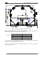
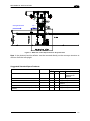
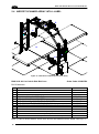
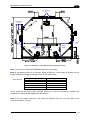
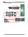
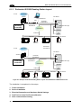
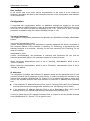
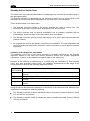
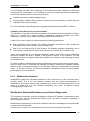
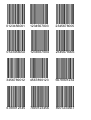
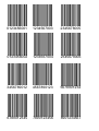
Reliability and robustness of the system can be improved by connecting scanners together in
a particular way. In case of failure for the redundancy cable, which connects the two PWOs
together, the active device only sees the scanners physically attached to the relative PWO.
In this case, the best result will be achieved if the scanners in question read as much as
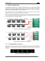
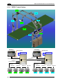
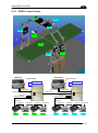
possible over the entire reading area. A possible solution to meet this request is to connect
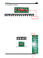
scanners alternatively, see pictures in the next pages.
6.3.1
DIP Switch Settings
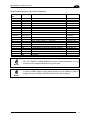
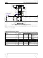
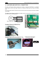
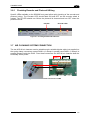
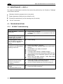
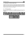
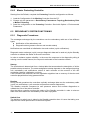
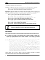
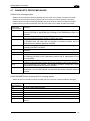
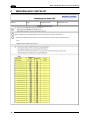
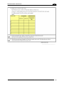
Decide which SC6000/PWO group will be the Working Controller and which will be the
Protecting Controller. Consequently set the switches in each PWO-480 as shown in the
following table.
Topology
Role
Working
Protecting
LON TERM
IN3
REDUNDANCY
SRC
ON
ON
PWR PWR
1
1
1
1
1
1
RE
RE
STD
STD
ON
ON
PWR PWR
1
1
1
1
1
1
RE
RE
REV
REV
Scanners
8K TERM
8K BYP
8K only
ON
ON
OFF
OFF
6K only
OFF
OFF
ON
ON
Both 6K and 8K
OFF
OFF
OFF
OFF
SEL
45