1
Program Timing and Execution
When programming the multimeter at the register level, the structure of the
program will generally be as follows:
– resetting the multimeter
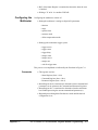
– configuring the multimeter
– retrieving the measurements
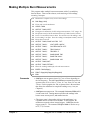
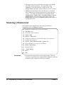
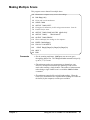
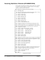
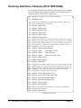
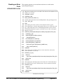
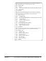
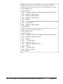
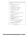
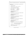
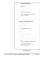
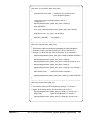
This section contains generalized flowcharts and comments for performing
these and other procedures. The flowcharts identify the registers used and
the status bits monitored to ensure execution of the program.
Resetting the
Multimeter
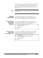
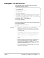
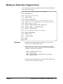
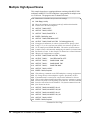
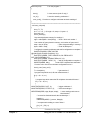
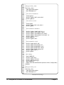
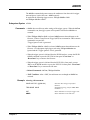
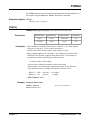
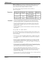
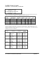
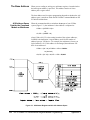
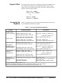
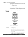
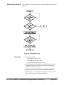
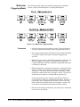
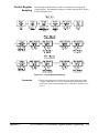
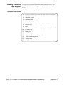
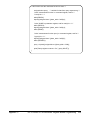
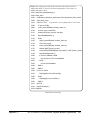
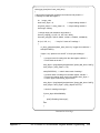
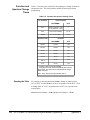
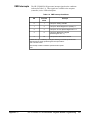
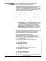
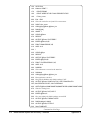
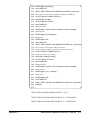
The multimeter is reset as indicated in Figure C-3.
Figure C-3. Resetting the Multimeter
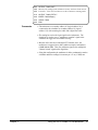
Comments
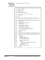
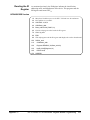
• The registers used are:
– Control Register (base + 0416)
– Status Register (base + 0416)
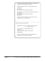
• Writing a "1" to bit 1 prevents the multimeter from asserting the
SYSFAIL line when the multimeter is reset. (If SYSFAIL is enabled
when a reset occurs, the multimeter is taken off-line by the system
Resource Manager.)
• Writing a "1" to bits 1 and 0 keeps SYSFAIL disabled and resets the
multimeter. This condition must remain for at least 2 µs for the reset
to complete. Writing a "0" to bit 0 turns the reset function off.
210
HP E1326B/E1411B Multimeter Register-Based Programming
Appendix C