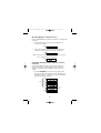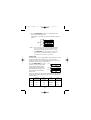
1
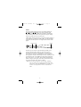
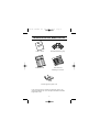
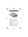
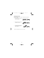
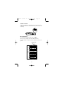
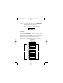
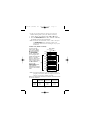
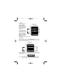
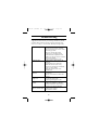
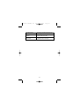
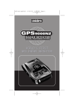
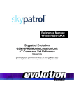
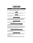
GLOBAL POSITIONING SYSTEM AND 360˚ LASER DETECTOR
Uniden’s GPSRD radar detector provides
patented artificial intelligence technology
which calculates your driving patterns
to eliminate falsing.
UTILIZES MILITARY SATELLITE TECHNOLOGY
Manual del usuario
UTILIZA LA TECNOLOGÍA MILITAR DE SATÉLITE
El detector de radar GPSRD de Uniden le
provee una tecnología de inteligencia
artificial patentada, la cual calcula sus
hábitos de conducción para eliminar las
señales falsas (falsing).
SISTEMA DE POSICIÓN GLOBAL Y DETECTOR LÁSER DE 360˚
GPSRD OM Eng&Spn cover
9/4/01
13:50
Page i
US076Z (GPSRD) OM
9/4/01
13:38
Page iii
Precautions
Important:
The GPSRD was not designed to help you
disobey the law. Safe drivers always obey the
posted speed limit and legal driving methods at
all times.
Federal and Local Regulations
The FCC passed the Communications Act in 1934 to give all
citizens the right to receive any type of radio transmission. The
same radio frequencies used by police radar are also used by
other devices, such as automatic door openers, burglar alarms,
and some amateur radio equipment. Since the GPSRD is just a
radio receiver tuned to a specific portion of the public radio
spectrum, it is protected under this act.
Some local, state, and federal regulations may prohibit the use of
this detection device. Please check with authorities regarding the
use of this device before operating it.
Since the GPSRD determines its positioning from GPS (Global
Positioning System), a navigational positioning system whose
operation is controlled by the Department of Defense (USA), its
performance may be limited by the operational conditions
controlled.
Operation Notice
Safety Warning Systems
You have purchased the newest technology designed for Radar,
Laser and Safety Warning System detection and alert. You
should be aware that Safety Warning transmitters (the device that
alerts your detector for safety warning alerts) will be available
for use throughout the United States. However, these transmitters
may not be used in all areas.
While this detector is designed to warn you of road hazards, it is
not designed as a substitute for safe, attentive driving
procedures. Drivers are reminded to remain alert for road
hazards at all times.
US076Z (GPSRD) OM
9/4/01
13:38
Page iv
Operation Notice of GPS
GPS signal reception can be affected by the location of satellites,
tall buildings, tunnels, bridges, etc. If the GPSRD is not
receiving a signal, you will need to change your location until a
signal is received.
The GPSRD will only receive satellite broadcasts from satellites
that have an elevation above the horizon of 5 degrees or more.
For optimal GPS signal reception the GPSRD should be
mounted on the lower part of the windshield.
The latitude, longitude, and altitude indications on the display
are based on WGS-84 Datum, and usable in North America and
Canada only. These indications may not be accurate in other
areas, and the altitude indication may not appear even in North
America and Canada depending on the signal conditions from
GPS satellites.
GPS Warnings
* For safety reasons it is not recommended that the driver
change any settings while in motion. Please come to a
complete stop or have a passenger make changes if
necessary.
* The Global Positioning System is operated and maintained
by the US Government. The US Government is completely
responsible for the accuracy of the Global Positioning
System.
* The US Government reserves the right to make changes to
the Global Positioning System in accordance with the
Department of Defense civil GPS user policy and the
Federal Radionavigation plan. These changes along with
poor satellite geometry could cause inaccurate readings.
* This device is excellent for navigation, however it does not
replace the need for good judgment and common sense.
* All information provided is for reference only. The user
assumes all responsibility and risks when operating this
product.
US076Z (GPSRD) OM
9/4/01
13:38
Page v
Contents
Introduction . . . . . . . . . . . . . . . . . . . . . . . . . . . . . . . . . . . . 1
Feature Highlights . . . . . . . . . . . . . . . . . . . . . . . . . . . 3
Speed Detection Systems . . . . . . . . . . . . . . . . . . . . . . . . . . 4
Radar . . . . . . . . . . . . . . . . . . . . . . . . . . . . . . . . . . . . . 4
Laser. . . . . . . . . . . . . . . . . . . . . . . . . . . . . . . . . . . . . . 5
Included with Your Radar Detector . . . . . . . . . . . . . . . . . . . 6
Controls and Functions . . . . . . . . . . . . . . . . . . . . . . . . . . . . 7
Installation . . . . . . . . . . . . . . . . . . . . . . . . . . . . . . . . . . . . . 9
Helpful Tips . . . . . . . . . . . . . . . . . . . . . . . . . . . . . . . . 9
Adjusting the Windshield Mounting Clip . . . . . . . . . 10
Connecting the Power . . . . . . . . . . . . . . . . . . . . . . . . . . . . 11
Using the Cigarette Lighter Adapter . . . . . . . . . . . . . 11
Replacing the Fuse . . . . . . . . . . . . . . . . . . . . . . . . . . 12
Operation . . . . . . . . . . . . . . . . . . . . . . . . . . . . . . . . . . . . . 13
Power On . . . . . . . . . . . . . . . . . . . . . . . . . . . . . . . . . 13
Volume Control. . . . . . . . . . . . . . . . . . . . . . . . . . . . . 14
Menu Function . . . . . . . . . . . . . . . . . . . . . . . . . . . . . 14
1. Navigate. . . . . . . . . . . . . . . . . . . . . . . . . . . . . . . 15
2. Mark Loc (Mark Location). . . . . . . . . . . . . . . . . 17
3. Speeds . . . . . . . . . . . . . . . . . . . . . . . . . . . . . . . . 18
4. Position . . . . . . . . . . . . . . . . . . . . . . . . . . . . . . . 18
5. Database. . . . . . . . . . . . . . . . . . . . . . . . . . . . . . . 19
6. Alrt Lvl (Alert Level) . . . . . . . . . . . . . . . . . . . . . 19
7. Option . . . . . . . . . . . . . . . . . . . . . . . . . . . . . . . . 19
Warning Feature . . . . . . . . . . . . . . . . . . . . . . . . . . . . 19
City/Highway Mode . . . . . . . . . . . . . . . . . . . . . . . . . 20
False Area. . . . . . . . . . . . . . . . . . . . . . . . . . . . . . . . . 21
Trap Point . . . . . . . . . . . . . . . . . . . . . . . . . . . . . . . . . 23
Mute Operation. . . . . . . . . . . . . . . . . . . . . . . . . . . . . 24
Audio/Dimmer Operation . . . . . . . . . . . . . . . . . . . . . 24
Care and Maintenance. . . . . . . . . . . . . . . . . . . . . . . . . . . . 25
Troubleshooting . . . . . . . . . . . . . . . . . . . . . . . . . . . . . . . . 26
Specifications . . . . . . . . . . . . . . . . . . . . . . . . . . . . . . . . . . 28
One Year Limited Warranty. . . . . . . . . . . . . . . . . . . . . . . . 29
US076Z (GPSRD) OM
9/4/01
13:38
Page 1
Introduction
Welcome to the world of sophisticated, early warning laser/radar
detection with GPS (Global Positioning System). You have
purchased one of the most advanced laser/radar detectors
available. The GPSRD is a completely integrated laser/radar
detector. It responds to the X, K, and Ka band radar in use today
and also provides 360º detection of the latest speed monitoring
system − the laser gun. And the built-in Safety Warning System
(SWS™) is capable of detecting hazardous warning signals
transmitted on the K-band.
The GPSRD provides distinct visual and audio alerts to warn
you of the presence of X, K, and Ka band radar signals as well
as IR laser signals.
The GPSRD uses the new D.R.O. (Dielectric Resonant
Oscillator) and E.D.I.T. (Electronic Data Interference
Terminator) circuitry, giving more reliable performance.
GPS Features/Descriptions
■ Anti-Falling Database
a) Learning: Detects false alarm signals emitted from the door
sensors of buildings then stores their frequencies and the
location of these signals.
b) False alarm prevention: Deactivates its beep alert if it
receives signals having the same frequencies and locations
as those that are stored in memory.
The above learning and false alarm prevention are performed
automatically, and as a result, a great number of false alarms are
eliminated. Alarms will still occur under the following
circumstances:
• When receiving different frequency signals other than the
ones stored in memory.
• When receiving signals stronger than the level set in the
menu function. (See “False Area” on page 21)
Frequencies and locations stored in memory can be deleted by
1
US076Z (GPSRD) OM
9/4/01
13:38
Page 2
the following methods:
• When no driving is made in the same area for 1~2 months
after learning.
• When no interference signal of the same frequency exists
for 1~2 months after learning.
• User deletes stored information manually.
Note: A maximum of 5,000 locations can be stored in
memory. Once the memory is full the oldest data will
be deleted to make space for the new data collection.
■ Trap key
Pressing the Trap key will store the present location for an
automatic alert. This feature can be used to mark common speed
trap locations for advanced notice.
■ Alert Key
Pressing the Alert key will cancel a stored location caused by
actual police radar use. Press the Alert key when an actual police
gun is in use so that the location will not be stored as a falsing
location.
■ Navigation Feature
Navigational information such as time to go, latitude, longitude,
altitude, and a directional arrow for your destination will be
shown on the 8 digit LED display. For details regarding the
navigation feature, refer to page 15.
■ Preprogrammed City Database
Over 1,200 city coordinates are preprogrammed for user
selection. Simply choose your destination and the GPSRD will
show you the direction, time to go, average speed, etc. while
traveling to the city of choice.
We are certain that you will enjoy the GPSRD, and to ensure
that you get the most from its features, please read this
Operating Guide carefully before installing and operating
the unit.
2
US076Z (GPSRD) OM
9/4/01
13:38
Page 3
Feature Highlights
GPS Features
• Latitude & Longitude Display
• Elevation Display
• Top Speed Display
• Preprogrammed City Coordinates
• Electronic Compass
• Direction to Destination Arrow
• Average Speed Display
• Travel Timer
• Distance to Go
Radar Features
• 360º Laser Detection
• Anti-Falsing Database
• L2/L3™ Detection
• X, K, Ka Superwide Band Detection
• SWS™ Alert
• Auto Memory Retention Mode
• Mute Mode
• Text Message Readout
• City/Highway Modes
• Audio Only Mode
Other Features
• Language display changeable (English/Spanish/French)
• Unit display changeable (mile-feet/km-m)
3
US076Z (GPSRD) OM
9/4/01
13:38
Page 4
Speed Detection Systems
A speed detection device (often called a radar gun) sends out
either a microwave signal or beam of light. When this signal
reaches its target, part of the signal is reflected or bounced back
toward the emitting gun. The time required for the signal to
leave the gun, bounce off an object, and return is used to
determine a vehicle’s distance and speed.
Radar
Radar (Radio Detection and Ranging) is a microwave system for
detecting the speed of moving objects by reflected pulses of high
frequency radio waves. There are three radar bands (microwave
frequencies): X-band (10.49 to 10.56GHz), K-band (24.04 to
24.26 GHz), and Ka-band (34.4 GHz to 34.8 GHz).
The X-band was the first used for traffic, followed by the
K-band which is harder to detect (most instant-on radar is
K-band). The Ka-band was introduced in 1987. The GPSRD
monitors all current radar bands including laser.
The radar beam is cone shaped − the narrower the beam, the
greater the resolution. A moving vehicle reflects radar signals
back towards the radar gun. The GPSRD can detect the signals
emitted by radar guns, and it will sound an audio alarm and flash
a warning indicator.
For continuously transmitting radar, use the GPSRD to get
accurate detection from a safe distance. Weak signals cause the
audio and visual alarms to sound intermittently, but as the signal
gets stronger (the closer you get to the radar gun), both alarms
increase in intensity.
Instant-on transmitters fire a short radar pulse beam at a vehicle.
When detected at a distance, you will hear a few beeps and see
the strength meter begin to light. Instant-On radar signals are the
most difficult to detect at a safe distance because they are
transmitted only when directed at you or at a vehicle directly
ahead of you.
4
US076Z (GPSRD) OM
9/4/01
13:38
Page 5
Laser
The Laser Speed Detection System, also called LIDAR (for
Light Detection and Ranging), uses a laser gun that emits
infrared light pulses just outside the spectrum of visible light.
Each reflected pulse measures the speed of the object coming
toward, or going away from, the laser gun.
Unlike radar, the laser gun emits a very narrow beam of light, so
it can pinpoint a speeding car within traffic. The infrared beam
spreads out, but slowly and over a longer distance than a radar
signal.
0.25 miles 0.5 miles
1.55 miles
4.9 feet wide 9.8 feet wide
29.5 feet wide
The laser gun can acquire a speed reading as quickly as 0.3
seconds, sometimes less. However, since it isn’t easy to
accurately aim at and hit a moving target, an operator often
moves the laser gun in several directions to get a reading. So
laser signals are emitted continuously for a few seconds for each
speed measurement. The GPSRD can detect these light pulses
from as far away as 1.55 miles, which is about four times the
effective range of a laser gun (0.39 miles), and about ten times
its average operating range (0.09-0.16 miles).
Note: To be safe, do not ignore any warnings. Although
there are other types of radar signals that may cause
interference, when the GPSRD detects a signal, be on
the alert. It is important to exercise caution at all
times.
5
US076Z (GPSRD) OM
9/4/01
13:38
Page 6
Included with Your Radar Detector
Owner’s Guide
Windshield Mounting Clip
Printed Material
Extra Fuse and
Mounting Accessories
Coiled Cigarette Lighter Cord
If any of these items are missing or damaged, contact your
dealer immediately. Be sure to complete and mail the Product
Registration Card.
6
US076Z (GPSRD) OM
9/4/01
13:38
Page 7
Controls and Functions
1
2
3
4
5
6
12
7
11
10
8
9
1.
360º Laser Detection Lenses − For 360º detection of laser
signals.
2.
Clip Release − Press the clip release button to set or remove
the GPSRD from the windshield mounting clip.
3.
CITY Key − With each press, the level to cut out weak
signals changes from 0 (min) to 4 (max). The level is set at
0 (Highway) initially and it is used to help reduce false
alarms while driving in the city.
4.
EXIT/ALERT Key − Press this key to leave portions of the
programming menu.
5.
MUTE Key − Press this key to set the audio mute feature
on/off. The detector sounds different alert tones according to
the mute mode setting.
6.
SELECT/TRAP Key − Press this key when using the
programming menu to choose your selection. Pressing this
key will also store commonly used areas for speed traps.
Once you have marked a location as a speed trap, the
GPSRD will alert you every time you drive near this marked
area.
7
US076Z (GPSRD) OM
9/4/01
13:38
Page 8
7.
▲ / ▼ Key − Press these keys to toggle through the
programming menu to view choices.
8.
LED Display − LED displays LASER/RADAR alerts, signal
strength, operation mode, and GPS information such as
direction, distance, etc.
9.
On-Off/Volume Control − Turns the power on (with a click)
and adjusts the audio alert volume.
10. 12V DC Power Input − Connect the DC power cord here.
Use only a Uniden® supplied power cord or its replacement.
11. Speaker − Sounds audio alerts. There are different alert
tones which distinguish each type of signal received.
12. GPS Antenna Window – Under this window is the GPS
antenna.
8
US076Z (GPSRD) OM
9/4/01
13:38
Page 9
Installation
The GPSRD uses a highly sensitive horn-type antenna and IR
laser sensor to receive radar/laser signals. Its sensitivity and
range depend on the method of installation and the direction of
the antenna/sensor in relation to the signal source. The inherent
nature of radar waves makes them reflect off metallic surfaces.
This is why these waves are so useful for measuring the speed of
a vehicle. The IR laser light may reflect only from shiny
surfaces. Both radar waves and IR laser light will, however, pass
through plastic or glass.
Before you decide where to put your radar detector, please keep
in mind these three important factors:
• For safety, do not mount the GPSRD in a location where it
will obstruct your driving vision.
• Most vehicles have the top part of the windshield tinted.
Mounting the GPSRD behind tinted or mirrored glass may
reduce the effectiveness of laser detection by reducing the
amount of laser light received by the detector.
• Do not mount the GPSRD in the path of an airbag.
Helpful Tips
The antenna and the forward looking
sensor are located behind the rear
panel of the unit, (and the rear- and
side-looking sensors are located on
top of the unit), directly behind the
mode selection keys. The antenna and sensors should not be
obstructed by metal or metallic surfaces and should be pointed at
the horizon for accurate long-range detection.
• Do not mount the unit behind the windshield wiper blades,
radio antenna, tinted glass area, or mirrored glass. Be sure
the unit is free from obstruction by seat backs, rear view
mirror, sun visors, or the ceiling of the automobile.
• Do not mount the unit in front of the heater or defroster vents.
• Make sure that the GPS antenna window has a clear view of
the sky.
9
US076Z (GPSRD) OM
9/4/01
13:38
Page 10
• Do not leave the unit in direct sunlight or in the glove
compartment of a closed car for long periods of time, as
extreme changes in temperature may cause internal damage.
Also, removing the unit from the windshield makes you less
susceptible to break-in and theft.
Adjusting the Windshield Mounting Clip
1.
The metal portion of the
bracket locks into the
plastic portion at three
different positions. These
positions can be used for
vehicles with different
vertical windshield angles.
The back position can be
used for vehicles with
windshields that are
slanted back.
2.
For optimum laser
detection, bend the angled
portion of the windshield
mounting bracket so that
the GPSRD is parallel to
the road surface. Be sure
the GPSRD is mounted so
it is free of obstructions
from seat backs, rear view
mirror, sun visors, or the
ceiling of the automobile.
There must be a clear 360º
line of sight to the outside
of the vehicle.
To mount the GPSRD:
1.
Insert the windshield clip into the GPSRD.
2.
Place the bracket and the GPSRD in the proper location on
the windshield of your vehicle, and press the suction cups
firmly against the windshield.
10
US076Z (GPSRD) OM
9/4/01
13:38
Page 11
Connecting the Power
Using the Cigarette Lighter Adapter
A coiled power cord provided with the unit has a cigarette
lighter socket plug at one end and a small connector at the other.
1.
Insert the small connector into the 12V DC power input on
the side of the unit.
2.
Insert the other end into the cigarette lighter socket of your
vehicle.
When installing the power cord, make sure that:
• The socket is clean to allow proper contact.
• The power cord does not block the antenna area.
Your unit also comes with ten power cord mounting clips. You
can use these clips to attach the power cord to the window frame
or other parts of the vehicle, keeping it neat and out of the way.
Use the double-sided foam tape squares to attach each clip. Slip
the power cord into the clip to hold it securely in place.
11
US076Z (GPSRD) OM
9/4/01
13:38
Page 12
Replacing the Fuse
The cigarette lighter plug contains a 1-ampere fuse to protect it
from power surges.
1.
To replace the fuse, unscrew
the top of the plug.
2.
Remove the fuse and replace
it with the same type.
3.
To replace the top, push in on
the two metal contacts and
twist into place.
Note: Your GPSRD comes with an extra fuse.
12
US076Z (GPSRD) OM
9/4/01
13:38
Page 13
Operation
You are now ready to enjoy the convenience and security of your
GPSRD. Please read this section of the Operating Guide carefully
to familiarize yourself with the basic operation of this unit.
Power On
Turn the Volume Control knob to turn power on. The GPSRD is
set to Demo mode and it performs a series of self-tests on its
radar detection displays and alert tones. After the self-tests of X,
K, Ka, Laser, L2, L3, VG2, and SWS, the display shows
“Welcome to Uniden GPSRD” scrolling as follows.
RED
RED
When all the characters on the display have been scrolled
through after the self-tests, the detector sets the modes that were
used last.
The display will then scroll, (searching for satellite). This will
indicate that the GPSRD is trying to acquire satellite
information.
The upper LED lights red during Demo mode and turns to green
when the detector receives signals from GPS satellites.
Note: • The detector stops Demo mode if it receives radar
signals, laser or GPS signals, approaches the
destination or Trap Point, or any one of its buttons
is pressed.
• You can operate all buttons even if the detector
cannot receive signals from the satellite, but some
functions won’t be available and will sound an
error tone.
13
US076Z (GPSRD) OM
9/4/01
13:38
Page 14
Volume Control
Adjust the Volume to a comfortable alarm tone level for your
vehicle. The volume level does not have any effect on the unit’s
sensitivity.
Increase
Volume
Off
Menu Function
To enter into the Menu function, press the ▲ key.
There are seven setting modes in the Menu function;
Navigate, Mark Loc, Speeds, Position, Database, Alrt Lvl, and
Option.
"Normal Mode"
[ ]SW
[EXIT/ALERT]SW
[ ]SW
[ ]SW
[ ]SW
[ ]SW
[ ]SW
[ ]SW
[ ]SW
[ ]SW
[ ]SW
[ ]SW
[ ]SW
[ ]SW
[ ]SW
[ ]SW
[ ]SW
[ ]SW
GREEN
GREEN
GREEN
GREEN
GREEN
GREEN
14
US076Z (GPSRD) OM
9/4/01
13:38
Page 15
Note: • To exit from the Menu function, press the EXIT/ALERT
key. If no key is pressed within 30 seconds, the
GPSRD will return to the display screen.
• If the detector cannot receive signals from the GPS
satellite, “-” and “?” may appear on the display.
RED
No GPS Satellite Signals
1. Navigate
To enter into this mode, select “Navigate” using the ▲ or ▼
keys. Press the SELECT/TRAP key. Use the ▲ or ▼ keys to select
the location you wish to program. Once the desired location is
displayed press the SELECT/TRAP key to program the location.
The display will confirm your choice with the readout of
“Selected”. The detector will display the distance, expected
necessary time, and etc. from the location where you are now.
"Menu Mode"
[SELECT/TRAP]SW
[EXIT/ALERT]SW
GREEN
[SELECT/TRAP]SW
GREEN
[ ]SW
[ ]SW
[ ]SW
[ ]SW
[ ]SW
[ ]SW
[ ]SW
[ ]SW
[ ]SW
[ ]SW
[ ]SW
[ ]SW
[ ]SW
[ ]SW
[ ]SW
[ ]SW
GREEN
GREEN
GREEN
[ ]SW
GREEN
[ ]SW
GREEN
GREEN
GREEN
GREEN
15
US076Z (GPSRD) OM
9/4/01
13:38
Page 16
• In the case of City, Dallas for example
1.
2.
3.
4.
5.
6.
7.
8.
Select “Navigate” using the ▲ or ▼ key.
Press the SELECT/TRAP key.
Select “City” using the ▲ or ▼ key.
Press the SELECT/TRAP key to indicate the states.
Select “Texas” using the ▲ or ▼ key.
Press the SELECT/TRAP key to indicate the cities.
Select “Dallas” using the ▲ or ▼ key.
Press the SELECT/TRAP key. After “Selected” indication,
GPS information such as the distance to the destination, etc.
appears on the display (Normal mode).
GREEN
[ ]SW
[ ]SW
[ ]SW
[ ]SW
GREEN
GREEN
[SELECT/TRAP]SW
GREEN
[ ]SW
[ ]SW
GREEN
[SELECT/TRAP]SW
GREEN
2sec later
Advancing direction
Speed
GREEN
[ ]SW
GREEN
[ ]SW
Distance to miles
GREEN
2.5sec later
[ ]SW
GREEN
Goal direction ( ↑ )
Expected neccesary time
16
US076Z (GPSRD) OM
9/4/01
13:39
Page 17
• In any case of other than City, you have to register the
latitude and longitude at first. (See Mark Loc Section)
1. Select “Home”, for example, using the ▲ or ▼ button.
2.
Press the SELECT/TRAP button. After “Selected” indication,
the display returns to the Normal mode.
Note: To deselect the destination, choose “OFF” then press
the SELECT/TRAP button. Choosing “OFF” will
eliminate the direction arrow showing the way to your
destination.
2. Mark Loc (Mark Location)
To enter into this
mode, select “Mark
Loc” using the ▲ or
▼ button, and press
the SELECT/TRAP
button. At this mode,
you can register the
latitude and longitude
data for 7 specific
points as shown in fig.
Select the point you
want to register using
the ▲ or ▼ button,
and press the
SELECT/TRAP button.
After “Marked”
indication, the display
returns to the Normal
mode.
"Menu Mode"
[SELECT/TRAP]SW
[EXIT/ALERT]SW
GREEN
[SELECT/TRAP]SW
GREEN
[ ]SW
[ ]SW
[ ]SW
[ ]SW
[ ]SW
[ ]SW
[ ]SW
[ ]SW
[ ]SW
[ ]SW
[ ]SW
[ ]SW
[ ]SW
[ ]SW
GREEN
GREEN
GREEN
[ ]SW
[ ]SW
GREEN
GREEN
GREEN
Note: If the Status Indicator is red, you will not be able to
program your location. Move to a different location in
order to receive better satellite reception.
When you approach the location, the detector sounds alert tones
in 3 levels as follows.
Level 1
Level 2
Level 3
Distance
(Radius/Mile)
1.0
0.5
0.1
Alert
Tone Time
3 sec
3 sec
3 sec
17
Alert
Display Time
3 sec
3 sec
3 sec
US076Z (GPSRD) OM
9/4/01
13:39
Page 18
3. Speeds
Select “Speeds” and
press the SELECT/
TRAP button. In this
mode, the detector
displays the maximum
or average speed data
stored in the GPS
module.
"Menu Mode"
[SELECT/TRAP]SW
[EXIT/ALERT]SW
GREEN
[SELECT/TRAP]SW
GREEN
[ ]SW
[ ]SW
GREEN
[ ]SW
Use the ▲ or ▼ keys [ ]SW
[ ]SW
[ ]SW
to toggle between the
GREEN
maximum and average
display. To delete the
[SELECT/TRAP]SW
GREEN
data, select “Delete?”
and press the SELECT/
2sec later
TRAP button.
“Deleted” will display to confirm that you have deleted both
maximum and average speed data.
4. Position
Select “Position” and press the SELECT/TRAP button. At this
mode, the detector displays the latitude, longitude, and altitude
data for your present location.
"Menu Mode"
[SELECT/TRAP]SW
[EXIT/ALERT]SW
GREEN
[SELECT/TRAP]SW
GREEN
[ ]SW
Latitude
[ ]SW
[ ]SW
[ ]SW
[ ]SW
GREEN
Longitude
GREEN
[ ]SW
Altitude
Use the ▲ or ▼ button to toggle between the displays. If GPS
satellite signals are not strong enough, the altitude display may
appear as follows.
GREEN
Note: If the Status Indicator is red, you will not be able to
view your location or altitude. Move to a different
location in order to receive better satellite reception.
18
US076Z (GPSRD) OM
9/4/01
13:39
Page 19
5. Database
Select “Database” and press the SELECT/TRAP key. In this mode,
you can delete the data for False Alerts and Trap Locations
programmed in the GPS module.
Select “False” or “Trap” with the ▲ or ▼ button, and press the
SELECT/TRAP button if you want to delete the data. The display
will show “Delete?”. After pressing SELECT/TRAP the display
will show “Cleaning”, then “Deleted” to confirm that the
database has been cleared.
As to the False Area and Trap Point, refer to pages 21 and 23 for
details.
Note: • “Cleaning” indication may last for a while until all
stored data is cleared. After all stored data is
cleared, the display indicates “Deleted” and
confirmation tone sounds
• The unit will immediately begin collecting data
again after cleaning the database.
6. Alrt Lvl (Alert Level)
Select “Alrt Lvl” and press the SELECT/TRAP button. In this
mode, you can set the level to sound the alert tone while driving
in the False Area.
The level is set at 2 initially and it is adjustable in 6 levels.
Refer to False Lockout Area on page 21 for details.
7. Option
Select “Option” and press the SELECT/TRAP button. In this mode,
you can change the unit and language on the display as follows.
Use the ▲ or ▼ key to display the language you wish, then
press the SELECT/TRAP key to confirm your choice.
Warning Feature
When the GPSRD detects a radar, laser, or safety warning signal,
it emits a distinct warning tone respectively. The detected band
name appears on the display as X, K, Ka, SW, VG, L, L2 or L3
along with its signal strength and speed indication. When the
signal gets stronger, more signal strength portions light up the
signal strength meter. You can use this meter to judge the
distance from the signal source as it gives you instant
information about the signal being detected.
19
US076Z (GPSRD) OM
9/4/01
13:39
Page 20
Example: X Band
GREEN
Signal LV 1
GREEN
Signal LV 2
GREEN
Signal LV 3
GREEN
Signal LV 4
GREEN
Signal LV 5
GREEN
Signal LV 6-7
Note: • The alert tones for the radar, laser, and SWS are all
different.
• The warning feature won’t be functional if you are
driving less than 10 MPH.
City/Highway Mode
You can change the detector’s sensitivity to activate its warning
feature according to your driving area.
Press the CITY key and
GREEN
the current setting level
[ CITY ]SW
will appear on the
GREEN
[ CITY ]SW
display. To change the
[ CITY ]SW
level, press the CITY key
again within 2 sec. The
GREEN
level is set at 0
(Highway) initially and
you may choose to increase the city mode from level 1 to 4
based on how sensitive you wish to set the detector.
Level 0
: This is the most sensitive setting. The
(Highway) detector will be more sensitive to distant
signals, but it also is more likely to false alarms.
Level 1~4 : The detector filters out weaker signals to reduce
(City)
false alarms, however you will not receive Audio
Warnings until you get closer to the source.
Note: Setting the city level to 4 greatly reduces the range for
receiving an audio alert.
20
US076Z (GPSRD) OM
9/4/01
13:39
Page 21
False Area
In highly populated areas, you may encounter many devices that
use the same frequencies as radar signals, such as motion
detectors, automatic doors, and intrusion alarms.
These devices may trigger an effect called “falsing”. To reduce
false alarms, the GPSRD is equipped with a newly developed
Anti-Falsing database (Common Falsing Area). While driving in
the city, the detector stores encountered interference signal
information automatically. When you drive in the same area at a
later time, the detector’s alert tone feature won’t be activated by
those signals unless their strength exceeds the predefined level
set as follows.
To adjust the level to sound the alert tone in the false area, select
“Alrt Lvl” and press the SELECT/TRAP key from the menu. The
present alert level appears on the display and it is adjustable in 6
levels.
Level 0: The alert tone sounds by all signals received.
Level 6: The alert tone sounds by strong signals only.
GREEN
[ ]SW
[ ]SW
[ ]SW
[ ]SW
[ ]SW
[ ]SW
GREEN
[ ]SW
[ ]SW
GREEN
Change the level with the ▲ or ▼ keys and press the
SELECT/TRAP button.
Note: • The alert level is effective in the false area only, and
the warning feature is active for all signals in other
areas.
• The detector stores approx. 5,000 areas. The stored
information is deleted automatically if you don’t
drive in the same area for a long time.
• Once the detectors memory is full, the detector will
delete one oldest data to make space for new
information.
21
US076Z (GPSRD) OM
9/4/01
13:39
Page 22
Warning Display in the False Area
When the GPSRD detects signals in the false area, it displays the
following:
1.
If the signal strength is less than the predefined level.
(No alert tone sounds.)
GREEN
2.
If the signal strength is more than the predefined level.
(Alert tone sounds.) Your current speed is displayed.
GREEN
Note: The display changes as shown if the detector cannot
receive signals from the GPS satellite.
RED
Switching On/Off the False Alarm Preventive
Function
Since the GPSRD stores false area information itself and
deactivates its alert tone automatically, you may want to be
alerted by all signals received regardless of the alert level
setting.
1.
Press the EXIT/ALERT key while receiving signals when
driving in the false area for the first time. The false alarm
preventive function is switched on or off, and the display
changes accordingly as follows:
GREEN
[ EXIT/ALERT ]SW
ON
OFF
GREEN
2 sec later
GREEN
[ EXIT/ALERT ]SW
GREEN
OFF
2 sec later
GREEN
22
ON
US076Z (GPSRD) OM
2.
9/4/01
13:39
Page 23
Press the EXIT/ALERT key while receiving signals when
driving in the same false area.
The function is switched on/off, and the display changes as
follows:
GREEN
[ EXIT/ALERT ]SW
ON
OFF
GREEN
2 sec later
GREEN
Note: • If the signal strength is more than the predefined
level, the vehicle speed will be indicated on the
display instead of the right 3 characters “STP”.
• The EXIT/ALERT key functions only at the present
false area to switch from GPSRD operation to
conventional radar detector operation.
Trap Point
The Trap Point is a user programmable location that can be used
to mark a common speed trap location. Once a location is
marked, the next time you approach the location, an alarm will
sound. You can mark up to 1,000 locations.
Press the SELECT/TRAP key at the
location you want to mark. After
“Trap” and the marked number
indication disappears from the
LED display, the display returns
to the Normal mode marked as
shown below.
GREEN
[ SELECT/TRAP ]SW
GREEN
2sec later
GREEN
When you approach the previously marked location, the detector
sounds alert tones and changes the LED color on the display in 3
levels as follows.
Distance
(Radius/Mile)
Level 1
0.5
Level 2
0.25
Level 3
0.1
Alert
Tone Time
3 sec
3 sec
3 sec
23
LED
Color
GREEN
ORANGE
RED
Alert
Display Time
3 sec
3 sec
3 sec
US076Z (GPSRD) OM
9/4/01
13:39
Page 24
Example:
GREEN
GREEN
Level 1
Note: • “TrapFULL” appears on the display with an error
tone if memory space for marking “Traps” is full.
• To clear the marked location, press the
SELECT/TRAP button while driving within the Level
3 “Trap” area. “CLR Trap” appears on the display.
Mute Operation
The detector changes its alert tones when the audio mute feature
is activated.
Press the MUTE button to indicate the mute mode set presently.
To toggle the mode, press the MUTE button again within
2 seconds.
GREEN
[ MUTE ]SW
GREEN
When the detector receives radar signals with the mute mode on,
it reduces the volume of the alert tones after emitting normal
alert tones for 3 seconds. Also, the alert tones emitted when
approaching a Trap Point or Mark Loc. are reduced in volume
with the default for mute mode is OFF.
Note: The default for mute mode is off.
Audio/Dimmer Operation
Press the CITY and the MUTE buttons simultaneously to select
one of the following modes.
Dimmer Off: Display lights normally
Dimmer On Middle: Display is dimmed
Dimmer On Low: Display is at its darkest level
Note: The default mode for dimmer is off.
24
US076Z (GPSRD) OM
9/4/01
13:39
Page 25
Care and Maintenance
The GPSRD is designed to give you years of trouble-free
service. There are no user-serviceable parts inside, and, except
for the fuse, no maintenance is required. To keep your detector
in new condition, follow these important suggestions:
• Never leave the GPSRD on the windshield when you park
your vehicle. The temperature in the vehicle in summer can
reach levels above what is considered safe for this unit.
• To make you less susceptible to break in and in theft,
remove the unit from your windshield when you leave
your vehicle.
• Do not expose the unit to moisture. Rain, dew, road splash,
or other liquids that can damage the internal components
and reduce sensitivity of the GPSRD.
25
US076Z (GPSRD) OM
9/4/01
13:39
Page 26
Troubleshooting
If your GPSRD does not perform to your expectations, try the
suggestions listed below. If you cannot get satisfactory results,
call the Uniden Customer Service Center at (800) 297-1023,
8:00 a.m. to 5:00 p.m. Central Time, Monday through Friday.
Unit does not operate: • Check the power cord. Be sure the
connectors are properly installed.
• Be sure ignition key is ON or in the
accessory position.
• Fuse out. Check and replace.
• Check power to lighter socket.
• Vehicle electrical problem exists.
• Make sure that the volume control is
in the ON position.
• Clean cigarette lighter socket.
Weak detection.
• Check angle of unit. Point to the
horizon.
• Antenna/Sensor is obstructed.
Relocate the unit clear of any
obstruction outside the windshield,
such as a wiper blade.
• Relocate the unit clear of the
window tint.
Inaccurate or erratic
• Loose power cord. Check both
detection:
connectors.
• Power cord is broken. Check and
replace.
Beeps over bumps or • Check that the power cord is
rough road.
connected at both ends.
• Clean cigarette lighter socket.
Beeps at same
• Up the Alert level. (See page 19)
location.
• Mount the GPSRD in a location
where the detector cannot receive
signals from the GPS Satellite.
Signal strength meter • Press the CITY button to adjust the
registers, but no audio. setting level properly.
• Increase the volume.
26
US076Z (GPSRD) OM
9/4/01
13:39
Page 27
The unit bounces
• Reposition so that the bumpers are
against the windshield. firmly against the windshield
If you still have a
• Call Uniden Customer Service
problem.
Center, (800) 297-1023.
No satellite
• Relocate to an area with a less
information.
obstructed view of the sky.
27
US076Z (GPSRD) OM
9/4/01
13:39
Page 28
Specifications
General
Dimensions:
Weight:
Power Requirement:
Temperature Range:
360º Laser Detector
Receiver Type:
Sensor Front End:
Detector Type:
Receiver Bandwidth:
Spectral Response:
Alert Hold Time:
Radar Detector
Receiver Type:
Detector Type:
Antenna Type:
Sensitivity:
Frequency of
Operation:
7.2 cm (W) × 12.1 cm (D) × 3.5 cm (H)
140 g
13.8 VDC
Operating: -5ºF to 160ºF
(-20ºC to 70ºC)
Storage: -40ºF to 185ºF
(-40ºC to 85ºC)
Pulse Laser Signal Receiver
Convex Condenser Lens
Pulse Width Discriminator
30 MHz
800 - 1100 nm
3 seconds
Double Conversion Superheterodyne
Self-Contained Antenna
Scanning Frequency Discriminator
Linear polarized, E vector vertical
X-band = -114 dBm/cm2
K-band = -104 dBm/cm2
Ka-band = -100 dBm/cm2
10.490 - 10.560 GHz (X-band)
24.040 - 24.260 GHz (K-band)
34.400 - 34.800 GHz (Ka-band)
GPS Navigator
Receiver Type
Parallel 12 channels spread spectrum
signal receiver
Antenna Type
Circular polarized dielectric patch
antenna
Positioning Accuracy 100 m (Probability 95%)
Features, specifications, and availability of optional accessories are all
subject to change without notice.
28
US076Z (GPSRD) OM
9/4/01
13:39
Page 29
One Year Limited Warranty
Important:
Please keep your sales docket as it provides
evidence of warranty. Warranty is only valid in
the country where the product has been
purchased.
WARRANTOR: Uniden America Corporation (“Uniden”)
ELEMENTS OF WARRANTY: Uniden warrants, for one year, to the original retail
owner, this Uniden Product to be free from defects in materials and craftsmanship
with only the limitations or exclusions set out below.
WARRANTY DURATION: This warranty to the original user shall terminate and be
of no further effect 12 months after the date of original retail sale. This warranty is
invalid if the product is: (A) Damaged or not maintained as reasonable or necessary,
(B) Modified, altered or used as part of any conversion kits, subassemblies, or any
configurations not sold by Uniden, (C) Improperly installed, (D) Serviced or repaired
by someone other than an authorized Uniden service center for a defect or malfunction
covered by this warranty, (E) Used in conjunction with any equipment or parts or as
part of any system not manufactured by Uniden, or (F) Installed or programmed by
anyone other than as detailed by the Operating Guide for this product.
STATEMENT OF REMEDY: In the event that the product does not conform to this
warranty at any time while this warranty is in effect, warrantor will repair the defect
and return it to you without charge for parts, service, or any other cost (except
shipping and handling) incurred by warrantor or its representatives in connection with
the performance of this warranty. THE LIMITED WARRANTY SET FORCE ABOVE
IS THE SOLE AND ENTIRE WARRANTY PERTAINING TO THE PRODUCT
AND IS IN LIEU OF AND EXCLUDES ALL OTHER WARRANTIES OF ANY
NATURE WHATSOEVER, WHETHER EXPRESS, IMPLIED OR ARISING BY
OPERATION OF LAW, INCLUDING, BUT NOT LIMITED TO ANY IMPLIED
WARRANTIES OF MERCHANTABILITY OR FITNESS FOR A PARTICULAR
PURPOSE. THIS WARRANTY DOES NOT COVER OR PROVIDE FOR THE
REIMBURSEMENT OR PAYMENT OF INCIDENTAL OR CONSEQUENTIAL
DAMAGES. Some states do not allow this exclusion or limitation of incidental or
consequential damages so the above limitation or exclusion may not apply to you.
LEGAL REMEDIES: This warranty gives you specific legal rights, and you may
also have other rights which vary from state to state. This warranty is void outside the
United States of America.
PROCEDURE FOR OBTAINING PERFORMANCE OF WARRANTY: If, after
following the instructions in this Operating Guide you are certain that the Product is
defective, pack the Product carefully (preferably in its original packaging). Include
evidence of original purchase and a note describing the defect that has caused you to
return it. The Product should be shipped freight prepaid by traceable means, or
delivered, to warrantor at:
Uniden America Corporation
Parts and Service
4700 Amon Carter Blvd.
Fort Worth, TX 76155
(800) 297-1023, 8:00 a.m. to 5:00 p.m. Central Time, Monday through Friday
29
GPSRD OM Eng&Spn cover
9/4/01
13:50
Page iii
!Gracias por la compra de un detector de rada de Uniden!
USZZ01076ZZ
Uniden® es una marca comercial registrada de Uniden America
Corporation.
4,698,632
5,315,302
6,169,511
4,709,407
5,469,287
4,791,420
5,579,012
4,831,498
5,835,052
Protegido por una o más de las siguientes patentes de EE.UU.
©2001 Uniden America Corporation, Fort Worth, Texas.
Todos los derechos reservados. Impreso en las Filipinas.
©2001 Uniden America Corporation, Fort Worth, Texas.
All rights reserved. Printed for Uniden in the Philippines.
Covered under one or more of the following U.S. patents.
4,698,632
5,315,302
6,169,511
4,709,407
5,469,287
4,791,420
5,579,012
4,831,498
5,835,052
Uniden® is a registered trademark of Uniden America Corporation.
USZZ01076ZZ
THANK YOU FOR PURCHASING A UNIDEN PRODUCT!