1
DTMF-16c
Touchtone® Decoder
CircuitWerkes
Technical Manual
CircuitWerkes
2805 NW 6th Street · Gainesville, FL 32609
(352) 335-6555 · Fax (352) 380-0230
http://www.circuitwerkes.com
© 1992-2003 CircuitWerkes All Rights Reserved. All information contained within is proprietary.
No part of this manual may be reproduced or copied without the express written consent of CircuitWerkes.
Touchtone ® is a registered trademark of AT&T.
1
2
Description
The CircuitWerkes DTMF-16 is an integrated Touch Tone detector and sixteen output decoder, offering
an optoisolated Darlington output for each of the sixteen standard DTMF tones. Seperate emitters and
collectors are available for each of the twelve "common" DTMF tones, 1-9, 0, *, and #. Seperate
Collectors and a common emitter are brought out for DTMF Tones A, B, C, and D. The open collector
Darlington outputs provide 5000 volts of isolation and are capable of sinking up to 150mA continuously
(emitter-collector voltage should not exceed 30 volts). These outputs along with 12 volts DC
(unregulated), and various internal test and interface signals are available at the unit's D-SUB 37 pin
connector. When interfacing the DTMF-16's outputs to low Voltage dc lines such as computer inputs,
etc the optocouplers provide greater isolation and do not contain mechanical parts to wear out as with
relays. It is not normally necessary or suggested to use external relays unless you are planning to switch AC
Voltages or audio signals. Correct polarity must be observed for the optocouplers to work.
Installation & Operation
Setup
The DTMF-16 comes from the factory ready to use, just hook up an audio source to the tip and ring (the
sleeve is left floating) on the DTMF-16's 1/4" audio input jack, connect your equipment to the supplied
DB37 male connector, plug in the power supply and it's ready. Typical hookup diagrams are supplied in
the schematics section at the end of this manual. The DTMF-16 has several user configurable options that
are set via internal jumpers.
The Mode jumper (J1) when "OPEN" selects momentary decoder operation. The momentary output is
activated only for the duration of the incoming DTMF tone. When the mode jumper is closed the decoder
is in (interlocked) latching mode. When in latching mode the selected output remains activated until
another output is selected. The second jumper (J2) enables the acknowledge beep when installed. The
acknowledge beep is fed back down the audio line & and is intended to provide an audible signal to the
operator when the DTMF-16 is used in conjunction with a telephone coupler to make a remote control.
The beep jumper is normally shipped in the open (off) mode when the DTMF-16 operates by itself .
The filter mode selectors allow you to configure your DTMF-16 for two alternate momentary modes.
In the "norm" position, the decoder provides quick detection of DTMF tones. If you are using the
interlocked latching mode, the jumper must be in the "norm" position. One of the most common trouble
calls that we get is from users who have gotten a decoder with the filter jumper (J3) set to either position
2 or 3. If you're having trouble with your unit, check J3's position first.
When set to the 2T position, the two tone sequence decoder is selected. In this mode, a specific "attention"
tone must be sent before each command. For instance, if the * key is selected as the attention tone and
you wanted to activate the number 1 output you would send {*1} to the decoder. You can select any of
the 16 standard DTMF tones to act as the attention signal by placing a jumper on the appropriate pins of
the 2x16 jumpers (J4) located between U3-6 and U2. The two tone mode provides three possible
advantages over the normal fast mode. First, it improves reliability by preventing false tripping from
transient audio passages. Second, it allows you to add up to 15 decoders to an audio line, each using
seperate attention tones. Lastly, the two-tone mode provides a slight level of security when used with
telephone couplers. The two-tone mode can not be used if the DTMF-16 is in the interlocked latching
mode. Do not jumper more than one tone at a time. While that usually won't damage anything, the
decoder also won't work properly, if at all. The second alternate mode delays detection of the DTMF tones
for a fraction of a second. The delay prevents the decoder from detecting transient audio passages
3
containing valid DTMF frequencies from being decoded. This anti-falsing delay provides reliable detection of
single DTMF tones that last for at least 1/2 second. Several satellite news/sports networks use long DTMF
tones for signalling affiliate breaks and cues. Neither filter mode is compatible with the latching output mode
because the filters disable the outputs after a few seconds.
The remaining four jumpers, labelled A-D hex data, are simply in the paths of the TTL level hexidecimal
data outputs of the decoder; they are normally installed in the open position at the factory. In the closed
position, the hex outputs appear on the D-37F output connector. If needed, the jumpers can be removed
and the corresponding four pins of the D-37F output connector can be accessed via the jumper/header
pins for other purposes. For example, special ComboLok options can be interfaced to the outside through
these pins.
Mounting
The basic DTMF-16 can be either desk or wall mounted. Keyhole cutouts on the ears of the enclosure
are provided for wall mounting. Two optional rack mounts, the RM-01 and RM-02 are also available
for those who would like to mount one or two DTMF-16s in a 19 inch rack cabinet.
Basic Operation
The DTMF-16 requires no operator intervention. It monitors an audio source until a valid DTMF tone
or combination sequence occurs, then energizes the tone's corresponding (Darlington output) optocoupler.
The resulting open collector output appears on the unit's db37 connector.
Connections
The power connection is made via 2.1 mm coaxial jack and will accept from 8 to 18 Vac. A power supply
is provided with each DTMF-16; however, if you wish to supply your own, it must be able to provide at
least 150ma.
The DTMF-16's audio connection is made via the 1/4 inch jack located next to the power connector. The
connector is a tip, ring & sleeve type with the tip & ring making the audio path. The audio input is an
unbalanced input with an input impedance of approximately 10kOhms.
Audio input level should be between 0.1 and 5 volts peak to peak
Each DTMF digit is assigned to an optocoupler. For the 12 standard tones, each optocoupler's emitter
& collector is available at the D37f connector. The emitters of tones A-D share a common output pin.
When a tone is detected, the resistance of the optocoupler drops to a few ohms which emulates a contact
closure for most dc applications. Most low or medium powered switching can be done directly from the
optocouplers. Computer or logic inputs can also be directly driven from the optocoupler outputs. For
higher Voltage/higher current loads, the optocouplers can drive most external relays. A sample hookup
diagram of a computer/logic connection and a relay connection can be found on page 9 of this manual.
The optocouplers are polarity sensitive and will conduct in one direction only, so the emitter should
always be closer to negative (or ground) than the collector. As with relay closures, the individual
optocouplers may be tied together in parallel if desired.
Care & Feeding
Generally, the DTMF-16 may be placed anywhere other electrical equipment is in operation. As
always, it is best to avoid extreme temperatures, immersion, or high impacts.
If you wish to clean the outside of the DTMF-16, use a damp cloth soaked in a mild soap and water
solution. Detergents, alcohol, or solvents may remove the screen printing or mar the case.
4
Theory of operation
Input audio is capacitor coupled to the Motorola 145436 low power DTMF receiver. The MC145436
requires only one resistor and one crystal for frequency reference. The hexadecimal coded output is
decoded by the CMOS 4514 4 to 16 line decoder. The hex-coded BCD data is connected directly to the
4514 decoder; but the data valid (strobe) pulse from the MC145436 drives the bases of two npn switching
transistors, q1 and q2. q2's sole purpose in life is to be an inverter/buffer of the DV pulse for the accessory
header (2x4 pin header) located beside the 4514 chip and the DV LED. Q1, more importantly, pulls up
the Follow pin (pin 1 a.k.a. strobe) on the 4514 and turns on transistor q3 during the DV pulse. When
q3 is thus energized, it pulls the INHibit pin (pin 23) of the 4514 low, enabling the chip to place a high
on the output selected by the MC145436's hex-coded BCD data. The high going outputs of the 4514 drive
optocouplers u3 through u6. Diodes d2 and d3 connect the base of q4 and q3 to the enable/disable pin
of the 2 by 5 header and the disable pin of the d37f connector. When either pin is grounded, the decoder
is disabled.
Q1's high-going (trailing) edge triggers the DTMF acknowledge beep circuit. After Q1 turns off, r8 pulls
the the line low through Q5. Q5 is a gate controlled by Q4 so that no beeps occur until the second tone
of a 2-tone sequence or if the unit is disabled by the combination lock option. The 4093's pin 1 (u7a) goes
low for a short period of time (determined by c9 and r12) after q1's high-going edge occurs which gates
the oscillator (formed by u7d, u7c, c8, r10, and r11) for the duration of the pulse. The resluting short burst
of mdirange square waves is cap coupled to the audio input via jumper J2 so that any valid DTMF tones
is followed by a brief acknowledge beep. If the DTMF-16 is not being used in a situation where a
confirmation that the DTMF tone was decoded is desired, jumper J2 or J2b can be pulled to disable the
beep.
When the decoder is set (via jumper 1) to interlocked latching mode, the base of transistor q3 is held high
which pulls the INHibit pin of the 4514 low, keeping the last-selected output activated until a new DV
pulse (accompanied by new BCD data) occurs. Diode d1 prevents Vcc through r9 from flowing back
through the buffered DV circuit when J1 is on.
The filter select jumper allows the user to select between normal operations, a two tone sequence decoder
or an anti-falsing delay filter. When the filter select jumper, J-3, is set to the normal mode (position 1),
transistor q4 is always on, enabling the outputs. Q4's primary function is to turn the outputs off when J3
is set to either of the two filter modes until the appropriate signals or timing have occurred. Q4 controls
the operation of all optocouplers by sinking the cathode buss to ground. When J3 is set to the 2T mode
(position 2), the high going output of the 4514 chip must be sent via the tone select jumper (J4) to c11,
a .1uF capacitor. C11 charges during the output pulse, but then suddenly discharges at the end of the pulse
pulling u7b's input momentarily low. U7b inverts the signal and causes u8's output to drop low, quickly
discharging c12 via d6 & r19. When c12 is discharged, u8c goes high, turning on q4 & enabling the
optocouplers.. Q4 remains on for a few seconds while c12 slowly charges via r18. When the filter select
jumper is set to AF (position 3), buffered high going DV from q1 is fed to the inputs of u8a causing its
output to go low, slowly discharging c7 through r20. When c7 is discharged, the output of u8d goes high
enabling the optocouplers through q4.
The 4514 directly drives the 16 darlington optocouplers to saturation. The Optocouplers are quad
packaged for higher density board designs. A PC Board silk screen legend shows which optocouplers are
associated with their tones. An onboard 5 volt regulated supply easily handles the circuit's power needs.
5
Trouble Shooting
Problem:
Solution:
No outputs function and there is no BCD data on pins 1, 2, 13, or 14 of the 145436.
No DV LED.
Power supply failure (check bridge first), improper audio input (check the audio input
jack to see if it's making proper contact with your plug. Sometimes the jack's pins
get bent out of place when plugging in.), bad MC145436 or damaged crystal
Problem:
Solution:
DTMF-16 outputs test good but won't activate my equipment.
Polarities may be reversed. Optocouplers will conduct in one direction only. In
some computer related cases, a different version of the DTMF-16 output chip may be
required, replacements are available free from the factory. Adding an external relay
can also solve this problem.
Problem:
Cause:
One or more outputs do not operate with an incoming tone. Beep & DV LED work.
Failed optocoupler(s), failed 4514, bad, q3 or d1 zotched. Is J3 in the right position
for your situation? Try setting it to the normal mode (pos. 1). Distorted DTMF tone.
Problem:
Cause:
No outputs will operate with an incoming tone, no beep. DV LED works.
Q1 is fried.
Problem:
None of the outputs function with incoming tones; 4514 outputs go high
(approx 1-2 V) during appropriate tones. DV LED lights during tones.
Incorrectly wired output connector, bad q4 or r14 open - missing,
improperly placed or missing filter select jumper.
Cause:
Problem:
Cause:
Problem
Cause:
None of the outputs function with incoming tones; BCD data (during incoming tone)
good at pins 1, 18, 17, 16 of the but, no output of 4514.
Incorrectly wired output connector (pin 1 grounded), bad 4514, bad q1, q3 or r3/r4
open, missing.
No beep. Outputs functioning properly on db37.
4093 failed Q5 blown or "beep" jumper removed.
The DTMF-16c has a red LED marked DV that should light whenever a tone is detected. If you have
problems, check that LED for operation during a tone. If it's not operating, then there's an audio input
problem with input jack/plug or your wiring or the MC145436 chip/ associated circuit is bad. If you have
an amplified speaker, listen to your source audio at the jack's wiring connector to verify that the audio is
getting that far. If the light does come on, then hook up your external connectors in the normal way that
they will be used and, using a D.C. Voltmeter (preferrably analog), look at the two pins associated with
the tone that you are using. When there is no tone, you should see Voltage from whatever source you're
trying to switch. Verify that the collector pin is high and that the emitter is low. If they are reversed, the
unit will not work. If there's no Voltage from your source, then either your source is bad or your wiring
is faulty. If there is Voltage, then verify that it's not more than 30 Volts and wait for a tone. During the
tone, the Voltage should fall to nearly zero. If it does, then the decoder is working. If not, then there is
a problem with the 4514 chip, an output chip or an internal jumper such as J3. If you suspect an output
chip, there are 4 identical chips, each containing 4 optocouplers. You can swap them around to test any
particular output.
Note: Excessive current or Voltage
through the emitter collector junction of
the NEC optocouplers will destroy them.
6
Options
The Silencer option board, combined with your DTMF-16 lets you recieve DTMF control signals
while completely removing the tones from your audio path. Your talent or producer in the field can
fire ID's, start breaks, fully automated remote broadcasts, light up an attention flasher, or control just
about anything else right in the program path, without getting any tones on the air. On channel,
Silenced, DTMF tones easily allow for sophisticated network control without the expense of
additional control channels. The Silencer can be field retrofitted in this version of the DTMF-16.
Contact your CircuitWerkes Dealer for more information on CircuitWerkes products.
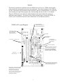
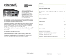
J2 - Acknowledge beep
On - Enable acknowledge tone
Off - Disable acknowledge tone
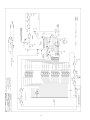
DTMF-16C Layout Diagram
Audio Input Connector.
Tip (+) and Ring (Gnd).
Sleave is not used.
10k unbalanced input.
Power LED
Valid DTMF tone
detected LED
J1 - Mode Jumper
On - Latching (see text)
Off - Momentary
Power input. 7 to 24V ac or dc.
10 pin accessory header
Attention tone selector (J4)- Used in
conjunction with the two-tone filter
jumper to select which DTMF tone
will enable the decoder. DO NOT
jumper more than 1 tone at a time.
37 pin D-sub
output connector
Filter Set Jumper(J3)- Selects between
normal (fast response) mode, two-tone
mode or anti-falsing delay mode.
Hex data/Db-37 output jumpers/header
Normally jumpered, can be removed
(disabling the hex data outputs)
so that the corresponding D-Sub
pins (2, 3, 4, & 23) can be used by other
assemblies in the product enclosure,
like the optional Silencer.
7
8
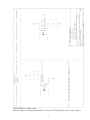
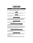
Typical DTMF-16 output wiring.
Specific examples for interfacing the DTMF-16 to relays and TTL/CMOS inputs can be found on page 9.
9
C
D
10
5
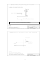
Regulated 5Vdc at up to 70mA is available at pin 22 for powering external devices such as relays.
Pin 21 is ground. Larger external relays must be powered from an external supply.
11
REPAIR OR SERVICE
INFORMATION
In the event of the need for service or
repair, call CircuitWerkes at (352) 3356555 for a Return Merchandise Authorization number (RMA). Then carefully
package the unit along with a note of the
problem and send it to the address below.
Clearly indicate the RMA number on the
outside of the box. We cannot accept
returns without an RMA. Be sure to
include your address (not a PO box),
telephone number and best time to call.
CircuitWerkes
ATTN: CUSTOMER SERVICE DEPT.
2805 NW 6th Street
GAINESVILLE, FL 32609
CircuitWerkes Limited Warranty
This product is warranted against defects for two years from date of
purchase from CircuitWerkes and CircuitWerkes authorized distributors.
Within this period, we will repair it without charge for parts and labor.
Proof of purchase-date required. Warranty does not cover
transportation costs, or a product subjected to misuse, accidental
damage, alteration (except as authorized by CircuitWerkes),
improper installation, or consequential damages.
Except as provided herein, CircuitWerkes makes no warranties, express
or implied, including warranties of merchantability and fitness for a
particular purpose. Some states do not permit limitation or exclusion
of implied warranties; therefore, the aforesaid limitation(s) or
exclusion(s) may not apply to the purchaser. This warranty gives you
specific legal rights and you may also have other rights which vary from
state to state.
12