1
RoamAbout ®
Switch Manager
User’s Guide
Version 5.0
P/N 9034144-04
Notice
Enterasys Networks reserves the right to make changes in specifications and other information contained in this document and its web site without prior notice. The reader should in all cases consult Enterasys Networks to determine whether any such changes have been made.
The hardware, firmware, or software described in this document is subject to change without notice.
IN NO EVENT SHALL ENTERASYS NETWORKS BE LIABLE FOR ANY INCIDENTAL, INDIRECT, SPECIAL, OR CONSEQUENTIAL DAMAGES WHATSOEVER (INCLUDING BUT NOT LIMITED TO LOST PROFITS) ARISING OUT OF OR RELATED TO THIS DOCUMENT, WEB SITE, OR THE INFORMATION CONTAINED IN THEM, EVEN IF ENTERASYS NETWORKS HAS BEEN ADVISED OF, KNEW OF, OR SHOULD HAVE KNOWN OF, THE POSSIBILITY OF SUCH DAMAGES.
Enterasys Networks, Inc.
50 Minuteman Road
Andover, MA 01810
© 2006 Enterasys Networks, Inc. All rights reserved.
Part Number: 9034144‐04 November 2006
ENTERASYS NETWORKS, ENTERASYS, ENTERASYS ROAMABOUT, ROAMABOUT and any logos associated therewith, are trademarks or registered trademarks of Enterasys Networks, Inc. in the United States and other countries. AirDefense is a trademark of AirDefense Incorporated.
Adobe, Acrobat, and Acrobat Reader are registered trademarks of Adobe Systems Incorporated.
Intel, Pentium, and Xeon are trademarks or registered trademark of Intel Corporation.
SUSE is a registered trademark of Novell, Inc.
Linux is a trademark of Linus Torvalds. Macintosh is a registered trademark of Apple.
Microsoft, Windows, and Windows NT are trademarks or registered trademarks of Microsoft Corporation.
Netscape is a registered trademark of Netscape Communications Corporation.
Red Hat is a registered trademark of Red Hat, Inc.
Solaris is a trademark of Sun MicroSystems, Inc.
UNIX is a registered trademark of The Open Group. All other product names mentioned in this manual may be trademarks or registered trademarks of their respective owners.
Documentation URL: http://www.enterasys.com/support/manuals
Documentacion URL: http://www.enterasys.com/support/manuals
Dokumentation im Internet: http://www.enterasys.com/support/manuals
i
Enterasys Networks, Inc.
Firmware License Agreement
BEFORE OPENING OR UTILIZING THE ENCLOSED PRODUCT,
CAREFULLY READ THIS LICENSE AGREEMENT.
This document is an agreement (“Agreement”) between the end user (“You”) and Enterasys Networks, Inc. on behalf of itself and its Affiliates (as hereinafter defined) (“Enterasys”) that sets forth Your rights and obligations with respect to the Enterasys software program/firmware installed on the Enterasys product (including any accompanying documentation, hardware or media) (“Program”) in the package and prevails over any additional, conflicting or inconsistent terms and conditions appearing on any purchase order or other document submitted by You. “Affiliate” means any person, partnership, corporation, limited liability company, or other form of enterprise that directly or indirectly through one or more intermediaries, controls, or is controlled by, or is under common control with the party specified. This Agreement constitutes the entire understanding between the parties, and supersedes all prior discussions, representations, understandings or agreements, whether oral or in writing, between the parties with respect to the subject matter of this Agreement. The Program may be contained in firmware, chips or other media.
BY INSTALLING OR OTHERWISE USING THE PROGRAM, YOU REPRESENT THAT YOU ARE AUTHORIZED TO ACCEPT THESE TERMS ON BEHALF OF THE END USER (IF THE END USER IS AN ENTITY ON WHOSE BEHALF YOU ARE AUTHORIZED TO ACT, “YOU” AND “YOUR” SHALL BE DEEMED TO REFER TO SUCH ENTITY) AND THAT YOU AGREE THAT YOU ARE BOUND BY THE TERMS OF THIS AGREEMENT, WHICH INCLUDES, AMONG OTHER PROVISIONS, THE LICENSE, THE DISCLAIMER OF WARRANTY AND THE LIMITATION OF LIABILITY. IF YOU DO NOT AGREE TO THE TERMS OF THIS AGREEMENT OR ARE NOT AUTHORIZED TO ENTER INTO THIS AGREEMENT, ENTERASYS IS UNWILLING TO LICENSE THE PROGRAM TO YOU AND YOU AGREE TO RETURN THE UNOPENED PRODUCT TO ENTERASYS OR YOUR DEALER, IF ANY, WITHIN TEN (10) DAYS FOLLOWING THE DATE OF RECEIPT FOR A FULL REFUND.
IF YOU HAVE ANY QUESTIONS ABOUT THIS AGREEMENT, CONTACT ENTERASYS NETWORKS, LEGAL DEPARTMENT AT (978) 684‐1000. You and Enterasys agree as follows:
1. LICENSE. You have the non‐exclusive and non‐transferable right to use only the one (1) copy of the Program provided in this package subject to the terms and conditions of this Agreement.
2. RESTRICTIONS. Except as otherwise authorized in writing by Enterasys, You may not, nor may You permit any third party to:
(i)
Reverse engineer, decompile, disassemble or modify the Program, in whole or in part, including for reasons of error correction or interoperability, except to the extent expressly permitted by applicable law and to the extent the parties shall not be permitted by that applicable law, such rights are expressly excluded. Information necessary to achieve interoperability or correct errors is available from Enterasys upon request and upon payment of Enterasys’ applicable fee.
(ii) Incorporate the Program, in whole or in part, in any other product or create derivative works based on the Program, in whole or in part.
(iii) Publish, disclose, copy, reproduce or transmit the Program, in whole or in part.
(iv) Assign, sell, license, sublicense, rent, lease, encumber by way of security interest, pledge or otherwise transfer the Program, in whole or in part.
(v) Remove any copyright, trademark, proprietary rights, disclaimer or warning notice included on or embedded in any part of the Program.
3. APPLICABLE LAW. This Agreement shall be interpreted and governed under the laws and in the state and federal courts of the Commonwealth of Massachusetts without regard to its conflicts of laws provisions. You accept the personal jurisdiction and venue of the Commonwealth of Massachusetts courts. None of the 1980 United Nations Convention on Contracts for the International Sale of Goods, the United Nations Convention on the Limitation Period in the International Sale of Goods, and the Uniform Computer Information Transactions Act shall apply to this Agreement. ii
4. EXPORT RESTRICTIONS. You understand that Enterasys and its Affiliates are subject to regulation by agencies of the U.S. Government, including the U.S. Department of Commerce, which prohibit export or diversion of certain technical products to certain countries, unless a license to export the Program is obtained from the U.S. Government or an exception from obtaining such license may be relied upon by the exporting party.
If the Program is exported from the United States pursuant to the License Exception CIV under the U.S. Export Administration Regulations, You agree that You are a civil end user of the Program and agree that You will use the Program for civil end uses only and not for military purposes.
If the Program is exported from the United States pursuant to the License Exception TSR under the U.S. Export Administration Regulations, in addition to the restriction on transfer set forth in Sections 1 or 2 of this Agreement, You agree not to (i) reexport or release the Program, the source code for the Program or technology to a national of a country in Country Groups D:1 or E:2 (Albania, Armenia, Azerbaijan, Belarus, Bulgaria, Cambodia, Cuba, Estonia, Georgia, Iraq, Kazakhstan, Kyrgyzstan, Laos, Latvia, Libya, Lithuania, Moldova, North Korea, the People’s Republic of China, Romania, Russia, Rwanda, Tajikistan, Turkmenistan, Ukraine, Uzbekistan, Vietnam, or such other countries as may be designated by the United States Government), (ii) export to Country Groups D:1 or E:2 (as defined herein) the direct product of the Program or the technology, if such foreign produced direct product is subject to national security controls as identified on the U.S. Commerce Control List, or (iii) if the direct product of the technology is a complete plant or any major component of a plant, export to Country Groups D:1 or E:2 the direct product of the plant or a major component thereof, if such foreign produced direct product is subject to national security controls as identified on the U.S. Commerce Control List or is subject to State Department controls under the U.S. Munitions List.
5. UNITED STATES GOVERNMENT RESTRICTED RIGHTS. The enclosed Program (i) was developed solely at private expense; (ii) contains “restricted computer software” submitted with restricted rights in accordance with section 52.227‐19 (a) through (d) of the Commercial Computer Software‐Restricted Rights Clause and its successors, and (iii) in all respects is proprietary data belonging to Enterasys and/or its suppliers. For Department of Defense units, the Program is considered commercial computer software in accordance with DFARS section 227.7202‐3 and its successors, and use, duplication, or disclosure by the Government is subject to restrictions set forth herein. 6. DISCLAIMER OF WARRANTY. EXCEPT FOR THOSE WARRANTIES EXPRESSLY PROVIDED TO YOU IN WRITING BY Enterasys, Enterasys DISCLAIMS ALL WARRANTIES, EITHER EXPRESS OR IMPLIED, INCLUDING BUT NOT LIMITED TO IMPLIED WARRANTIES OF MERCHANTABILITY, SATISFACTORY QUALITY, FITNESS FOR A PARTICULAR PURPOSE, TITLE AND NON‐ INFRINGEMENT WITH RESPECT TO THE PROGRAM. IF IMPLIED WARRANTIES MAY NOT BE DISCLAIMED BY APPLICABLE LAW, THEN ANY IMPLIED WARRANTIES ARE LIMITED IN DURATION TO THIRTY (30) DAYS AFTER DELIVERY OF THE PROGRAM TO YOU. 7. LIMITATION OF LIABILITY. IN NO EVENT SHALL ENTERASYS OR ITS SUPPLIERS BE LIABLE FOR ANY DAMAGES WHATSOEVER (INCLUDING, WITHOUT LIMITATION, DAMAGES FOR LOSS OF BUSINESS, PROFITS, BUSINESS INTERRUPTION, LOSS OF BUSINESS INFORMATION, SPECIAL, INCIDENTAL, CONSEQUENTIAL, OR RELIANCE DAMAGES, OR OTHER LOSS) ARISING OUT OF THE USE OR INABILITY TO USE THE PROGRAM, EVEN IF ENTERASYS HAS BEEN ADVISED OF THE POSSIBILITY OF SUCH DAMAGES. THIS FOREGOING LIMITATION SHALL APPLY REGARDLESS OF THE CAUSE OF ACTION UNDER WHICH DAMAGES ARE SOUGHT.
THE CUMULATIVE LIABILITY OF ENTERASYS TO YOU FOR ALL CLAIMS RELATING TO THE PROGRAM, IN CONTRACT, TORT OR OTHERWISE, SHALL NOT EXCEED THE TOTAL AMOUNT OF FEES PAID TO ENTERASYS BY YOU FOR THE RIGHTS GRANTED HEREIN. 8. AUDIT RIGHTS. You hereby acknowledge that the intellectual property rights associated with the Program are of critical value to Enterasys and, accordingly, You hereby agree to maintain complete books, records and accounts showing (i) license fees due and paid, and (ii) the use, copying and deployment of the Program. You also grant to Enterasys and its authorized representatives, upon reasonable notice, the right to audit and examine during Your normal business hours, Your books, records, accounts and hardware devices upon which the Program may be deployed to verify compliance with this Agreement, including the verification of the license fees due and paid Enterasys and the use, copying and deployment of the Program. Enterasys’ right of examination shall be exercised reasonably, in good faith and in a manner calculated to not unreasonably interfere with Your business. In the event such audit discovers non‐compliance with this Agreement, including copies of the Program made, used or deployed in breach of this Agreement, You shall promptly pay to Enterasys the appropriate license fees. Enterasys reserves the right, to be exercised in its sole discretion and without prior notice, to terminate this license, effective immediately, for failure to comply with this Agreement. Upon any such termination, You shall immediately cease all use of the Program and shall return to Enterasys the Program and all copies of the Program.
iii
9. OWNERSHIP. This is a license agreement and not an agreement for sale. You acknowledge and agree that the Program constitutes trade secrets and/or copyrighted material of Enterasys and/or its suppliers. You agree to implement reasonable security measures to protect such trade secrets and copyrighted material. All right, title and interest in and to the Program shall remain with Enterasys and/or its suppliers. All rights not specifically granted to You shall be reserved to Enterasys.
10. ENFORCEMENT. You acknowledge and agree that any breach of Sections 2, 4, or 9 of this Agreement by You may cause Enterasys irreparable damage for which recovery of money damages would be inadequate, and that Enterasys may be entitled to seek timely injunctive relief to protect Enterasys’ rights under this Agreement in addition to any and all remedies available at law. 11. ASSIGNMENT. You may not assign, transfer or sublicense this Agreement or any of Your rights or obligations under this Agreement, except that You may assign this Agreement to any person or entity which acquires substantially all of Your stock or assets. Enterasys may assign this Agreement in its sole discretion. This Agreement shall be binding upon and inure to the benefit of the parties, their legal representatives, permitted transferees, successors and assigns as permitted by this Agreement. Any attempted assignment, transfer or sublicense in violation of the terms of this Agreement shall be void and a breach of this Agreement.
12. WAIVER. A waiver by Enterasys of a breach of any of the terms and conditions of this Agreement must be in writing and will not be construed as a waiver of any subsequent breach of such term or condition. Enterasys’ failure to enforce a term upon Your breach of such term shall not be construed as a waiver of Your breach or prevent enforcement on any other occasion.
13. SEVERABILITY. In the event any provision of this Agreement is found to be invalid, illegal or unenforceable, the validity, legality and enforceability of any of the remaining provisions shall not in any way be affected or impaired thereby, and that provision shall be reformed, construed and enforced to the maximum extent permissible. Any such invalidity, illegality or unenforceability in any jurisdiction shall not invalidate or render illegal or unenforceable such provision in any other jurisdiction.
14. TERMINATION. Enterasys may terminate this Agreement immediately upon Your breach of any of the terms and conditions of this Agreement. Upon any such termination, You shall immediately cease all use of the Program and shall return to Enterasys the Program and all copies of the Program.
iv
Enterasys Networks, Inc. Software License Agreement
This document is an agreement (“Agreement”) between You, the end user, and Enterasys Networks, Inc. (“Enterasys”) that sets forth your rights and obligations with respect to the software contained in CD‐ROM or other media. BY UTILIZING THE ENCLOSED PRODUCT, YOU ARE AGREEING TO BECOME BOUND BY THE TERMS OF THIS AGREEMENT, WHICH INCLUDES THE LICENSE AND THE LIMITATION OF WARRANTY AND DISCLAIMER OF LIABILITY. IF YOU DO NOT AGREE TO THE TERMS OF THIS AGREEMENT, RETURN THE UNOPENED PRODUCT TO ENTERASYS OR YOUR DEALER, IF ANY, WITHIN TEN (10) DAYS FOLLOWING THE DATE OF RECEIPT FOR A FULL REFUND.
IF YOU HAVE ANY QUESTIONS ABOUT THIS AGREEMENT, CONTACT ENTERASYS NETWORKS, INC. (978) 684‐1000. ATTN: LEGAL DEPARTMENT.
Enterasys will grant You a non‐transferable, nonexclusive license to use the enclosed machine‐readable form of software (the “Licensed Software”) and the accompanying documentation (the Licensed Software, the media embodying the Licensed Software, and the documentation are collectively referred to in this Agreement as the “Licensed Materials”) on one single computer if You agree to the following terms and conditions:
1. TERM. This Agreement is effective from the date on which You open the package containing the Licensed Materials. You may terminate the Agreement at any time by destroying the Licensed Materials, together with all copies, modifications and merged portions in any form. The Agreement and your license to use the Licensed Materials will also terminate if You fail to comply with any term or condition herein.
2. GRANT OF SOFTWARE LICENSE. The license granted to You by Enterasys when You open this sealed package authorizes You to use the Licensed Software on any one, single computer only, or any replacement for that computer, for internal use only. A separate license, under a separate Software License Agreement, is required for any other computer on which You or another individual or employee intend to use the Licensed Software. YOU MAY NOT USE, COPY, OR MODIFY THE LICENSED MATERIALS, IN WHOLE OR IN PART, EXCEPT AS EXPRESSLY PROVIDED IN THIS AGREEMENT.
3. RESTRICTION AGAINST COPYING OR MODIFYING LICENSED MATERIALS. Except as expressly permitted in this Agreement, You may not copy or otherwise reproduce the Licensed Materials. In no event does the limited copying or reproduction permitted under this Agreement include the right to decompile, disassemble, electronically transfer, or reverse engineer the Licensed Software, or to translate the Licensed Software into another computer language.
The media embodying the Licensed Software may be copied by You, in whole or in part, into printed or machine readable form, in sufficient numbers only for backup or archival purposes, or to replace a worn or defective copy. However, You agree not to have more than two (2) copies of the Licensed Software in whole or in part, including the original media, in your possession for said purposes without Enterasys’ prior written consent, and in no event shall You operate more than one copy of the Licensed Software. You may not copy or reproduce the documentation. You agree to maintain appropriate records of the location of the original media and all copies of the Licensed Software, in whole or in part, made by You. You may modify the machine‐readable form of the Licensed Software for (1) your own internal use or (2) to merge the Licensed Software into other program material to form a modular work for your own use, provided that such work remains modular, but on termination of this Agreement, You are required to completely remove the Licensed Software from any such modular work. Any portion of the Licensed Software included in any such modular work shall be used only on a single computer for internal purposes and shall remain subject to all the terms and conditions of this Agreement.
You agree to include any copyright or other proprietary notice set forth on the label of the media embodying the Licensed Software on any copy of the Licensed Software in any form, in whole or in part, or on any modification of the Licensed Software or any such modular work containing the Licensed Software or any part thereof.
4.
TITLE AND PROPRIETARY RIGHTS. (a) The Licensed Materials are copyrighted works and are the sole and exclusive property of Enterasys, any company or a division thereof which Enterasys controls or is controlled by, or which may result from the merger or consolidation with Enterasys (its “affiliates”), and/or their suppliers. This Agreement conveys a limited right to operate the Licensed Materials and shall not be construed to convey title to the Licensed Materials to You. There are no implied rights. You shall not sell, lease, transfer, sublicense, dispose of, or otherwise make available the Licensed Materials or any portion thereof, to any other party.
(b) You further acknowledge that in the event of a breach of this Agreement, Enterasys shall suffer severe and irreparable damages for which monetary compensation alone will be inadequate. You therefore agree that in the event of a breach of this Agreement, Enterasys shall be entitled to monetary damages and its reasonable attorney’s fees and costs in enforcing this Agreement, as well as injunctive relief to restrain such breach, in addition to any other remedies available to Enterasys.
v
5. PROTECTION AND SECURITY. You agree not to deliver or otherwise make available the Licensed Materials or any part thereof, including without limitation the object or source code (if provided) of the Licensed Software, to any party other than Enterasys or its employees, except for purposes specifically related to your use of the Licensed Software on a single computer as expressly provided in this Agreement, without the prior written consent of Enterasys. You agree to use your best efforts and take all reasonable steps to safeguard the Licensed Materials to ensure that no unauthorized personnel shall have access thereto and that no unauthorized copy, publication, disclosure, or distribution, in whole or in part, in any form shall be made, and You agree to notify Enterasys of any unauthorized use thereof. You acknowledge that the Licensed Materials contain valuable confidential information and trade secrets, and that unauthorized use, copying and/or disclosure thereof are harmful to Enterasys or its Affiliates and/or its/their software suppliers.
6. MAINTENANCE AND UPDATES. Updates and certain maintenance and support services, if any, shall be provided to You pursuant to the terms of a Enterasys Service and Maintenance Agreement, if Enterasys and You enter into such an agreement. Except as specifically set forth in such agreement, Enterasys shall not be under any obligation to provide Software Updates, modifications, or enhancements, or Software maintenance and support services to You.
7. DEFAULT AND TERMINATION. In the event that You shall fail to keep, observe, or perform any obligation under this Agreement, including a failure to pay any sums due to Enterasys, Enterasys may, in addition to any other remedies it may have under law, terminate the License and any other agreements between Enterasys and You.
(a) Immediately after termination of the Agreement or if You have for any reason discontinued use of Software, You shall return to Enterasys the original and any copies of the Licensed Materials and remove the Licensed Software from any modular works made pursuant to Section 3, and certify in writing that through your best efforts and to the best of your knowledge the original and all copies of the terminated or discontinued Licensed Materials have been returned to Enterasys. (b) Sections 4, 5, 7, 8, 9, 10, 11, and 12 shall survive termination of this Agreement for any reason.
8. EXPORT REQUIREMENTS. You understand that Enterasys and its Affiliates are subject to regulation by agencies of the U.S. Government, including the U.S. Department of Commerce, which prohibit export or diversion of certain technical products to certain countries, unless a license to export the product is obtained from the U.S. Government or an exception from obtaining such license may be relied upon by the exporting party.
If the Licensed Materials are exported from the United States pursuant to the License Exception CIV under the U.S. Export Administration Regulations, You agree that You are a civil end user of the Licensed Materials and agree that You will use the Licensed Materials for civil end uses only and not for military purposes.
If the Licensed Materials are exported from the United States pursuant to the License Exception TSR under the U.S. Export Administration Regulations, in addition to the restriction on transfer set forth in Section 4 of this Agreement, You agree not to (i) reexport or release the Licensed Software, the source code for the Licensed Software or technology to a national of a country in Country Groups D:1 or E:2 (Albania, Armenia, Azerbaijan, Belarus, Bulgaria, Cambodia, Cuba, Estonia, Georgia, Iraq, Kazakhstan, Kyrgyzstan, Laos, Latvia, Libya, Lithuania, Moldova, North Korea, the People’s Republic of China, Romania, Russia, Rwanda, Tajikistan, Turkmenistan, Ukraine, Uzbekistan, Vietnam, or such other countries as may be designated by the United States Government), (ii) export to Country Groups D:1 or E:2 (as defined herein) the direct product of the Licensed Software or the technology, if such foreign produced direct product is subject to national security controls as identified on the U.S. Commerce Control List, or (iii) if the direct product of the technology is a complete plant o r any major component of a plant, export to Country Groups D:1 or E:2 the direct product of the plant or a major component thereof, if such foreign produced direct product is subject to national security controls as identified on the U.S. Commerce Control List or is subject to State Department controls under the U.S. Munitions List.
9. UNITED STATES GOVERNMENT RESTRICTED RIGHTS. The enclosed Product (i) was developed solely at private expense; (ii) contains “restricted computer software” submitted with restricted rights in accordance with section 52.227‐19 (a) through (d) of the Commercial Computer Software‐Restricted Rights Clause and its successors, and (iii) in all respects is proprietary data belonging to Enterasys and/or its suppliers. For Department of Defense units, the Product is considered commercial computer software in accordance with DFARS section 227.7202‐3 and its successors, and use, duplication, or disclosure by the Government is subject to restrictions set forth herein.
10. LIMITED WARRANTY AND LIMITATION OF LIABILITY. The only warranty Enterasys makes to You in connection with this license of the Licensed Materials is that if the media on which the Licensed Software is recorded is defective, it will be replaced without charge, if Enterasys in good faith determines that the media and proof of payment of the license fee are returned to Enterasys or the dealer from whom it was obtained within ninety (90) days of the date of payment of the license fee.
NEITHER ENTERASYS NOR ITS AFFILIATES MAKE ANY OTHER WARRANTY OR REPRESENTATION, EXPRESS OR IMPLIED, WITH RESPECT TO THE LICENSED MATERIALS, WHICH ARE LICENSED “AS IS”. THE LIMITED WARRANTY AND REMEDY PROVIDED ABOVE ARE EXCLUSIVE AND IN LIEU OF ALL OTHER WARRANTIES, INCLUDING vi
IMPLIED WARRANTIES OF MERCHANTABILITY OR FITNESS FOR A PARTICULAR PURPOSE, WHICH ARE EXPRESSLY DISCLAIMED, AND STATEMENTS OR REPRESENTATIONS MADE BY ANY OTHER PERSON OR FIRM ARE VOID. ONLY TO THE EXTENT SUCH EXCLUSION OF ANY IMPLIED WARRANTY IS NOT PERMITTED BY LAW, THE DURATION OF SUCH IMPLIED WARRANTY IS LIMITED TO THE DURATION OF THE LIMITED WARRANTY SET FORTH ABOVE. YOU ASSUME ALL RISK AS TO THE QUALITY, FUNCTION AND PERFORMANCE OF THE LICENSED MATERIALS. IN NO EVENT WILL ENTERASYS OR ANY OTHER PARTY WHO HAS BEEN INVOLVED IN THE CREATION, PRODUCTION OR DELIVERY OF THE LICENSED MATERIALS BE LIABLE FOR SPECIAL, DIRECT, INDIRECT, RELIANCE, INCIDENTAL OR CONSEQUENTIAL DAMAGES, INCLUDING LOSS OF DATA OR PROFITS OR FOR INABILITY TO USE THE LICENSED MATERIALS, TO ANY PARTY EVEN IF ENTERASYS OR SUCH OTHER PARTY HAS BEEN ADVISED OF THE POSSIBILITY OF SUCH DAMAGES. IN NO EVENT SHALL ENTERASYS OR SUCH OTHER PARTYʹS LIABILITY FOR ANY DAMAGES OR LOSS TO YOU OR ANY OTHER PARTY EXCEED THE LICENSE FEE YOU PAID FOR THE LICENSED MATERIALS.
Some states do not allow limitations on how long an implied warranty lasts and some states do not allow the exclusion or limitation of incidental or consequential damages, so the above limitation and exclusion may not apply to You. This limited warranty gives You specific legal rights, and You may also have other rights which vary from state to state.
11. JURISDICTION. The rights and obligations of the parties to this Agreement shall be governed and construed in accordance with the laws and in the State and Federal courts of the Commonwealth of Massachusetts, without regard to its rules with respect to choice of law. You waive any objections to the personal jurisdiction and venue of such courts. 12. GENERAL.
(a) This Agreement shall not be assignable by You without the express written consent of Enterasys. The rights of Enterasys and Your obligations under this Agreement shall inure to the benefit of Enterasys’ assignees, licensors, and licensees.
(b) Section headings are for convenience only and shall not be considered in the interpretation of this Agreement.
(c) The provisions of the Agreement are severable and if any one or more of the provisions hereof are judicially determined to be illegal or otherwise unenforceable, in whole or in part, the remaining provisions of this Agreement shall nevertheless be binding on and enforceable by and between the parties hereto.
(d) Enterasys’ waiver of any right shall not constitute waiver of that right in future. This Agreement constitutes the entire understanding between the parties with respect to the subject matter hereof, and all prior agreements, representations, statements and undertakings, oral or written, are hereby expressly superseded and canceled. No purchase order shall supersede this Agreement.
(e) Should You have any questions regarding this Agreement, You may contact Enterasys at the address set forth below. Any notice or other communication to be sent to Enterasys must be mailed by certified mail to the following address: ENTERASYS NETWORKS, INC., 50 Minuteman Road, Andover, MA 01810 Attn: Manager ‐ Legal Department.
vii
viii
Contents
Introducing the Enterasys Networks Mobility System
Enterasys Networks Mobility System ...............................................................................................................xv
Documentation .................................................................................................................................................xv
Planning, Configuration, and Deployment ..................................................................................................xv
Installation ................................................................................................................................................. xvi
Configuration and Management ................................................................................................................ xvi
Safety and Advisory Notices ..................................................................................................................... xvi
Text and Syntax Conventions ................................................................................................................... xvi
Getting Help .................................................................................................................................................... xvii
Chapter 1: Getting Started
Hardware Requirements for RASM Client ...................................................................................................... 1-1
Hardware Requirements for RASM Services ................................................................................................. 1-2
Software Requirements .................................................................................................................................. 1-4
Preparing for Installation ................................................................................................................................. 1-4
User Privileges ......................................................................................................................................... 1-4
Serial Number and License Key ............................................................................................................... 1-5
HP OpenView Network Node Manager .................................................................................................... 1-5
Resource Allocation ................................................................................................................................. 1-5
RASM Services Options ..................................................................................................................... 1-6
Installing RASM .............................................................................................................................................. 1-7
Unpacking Files ........................................................................................................................................ 1-7
Windows ............................................................................................................................................. 1-7
UNIX and Linux .................................................................................................................................. 1-7
Apple Macintosh ................................................................................................................................. 1-7
Using the Installation Wizard .................................................................................................................... 1-8
Starting RASM Services ........................................................................................................................... 1-8
Start the RASM Services on a Unix or Linux System ......................................................................... 1-9
Stop the RASM services on a UNIX or Linux System ........................................................................ 1-9
Configure RASM Services as a daemon ............................................................................................1-9
To Start/Stop RASM Services on Macintosh Systems ....................................................................... 1-9
Connect RASM Clients to RASM Services....................................................................................... 1-10
Configure RASM Services ................................................................................................................ 1-11
Monitoring Settings........................................................................................................................... 1-12
RASM Access Control ............................................................................................................................ 1-12
RASM Interface ............................................................................................................................................ 1-13
Display the Main Window ....................................................................................................................... 1-13
Using the Toolbar and Menu Bar ........................................................................................................... 1-14
Setting Preferences .......................................................................................................................... 1-14
Easy Configuration Using Wizards ......................................................................................................... 1-15
Getting Help ........................................................................................................................................... 1-16
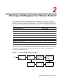
Chapter 2: Planning and Managing Your Wireless Network
Which Services to Provide? ............................................................................................................................ 2-2
Network Plan .................................................................................................................................................. 2-2
RF Coverage Area .......................................................................................................................................... 2-3
RF Auto-Tuning ........................................................................................................................................ 2-3
RF Auto-Tuning with Modelling ................................................................................................................ 2-3
RF Planning ............................................................................................................................................. 2-4
ix
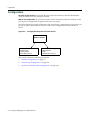
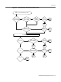
Which Planning Method Should I Use? .................................................................................................... 2-4
Configuration .................................................................................................................................................. 2-6
Wireless Configuration ............................................................................................................................. 2-7
AAA Security Configuration ...................................................................................................................... 2-8
Authentication..................................................................................................................................... 2-8
Authorization..................................................................................................................................... 2-10
Accounting........................................................................................................................................ 2-10
System and Administration Configuration .............................................................................................. 2-10
Configure Basic RoamAbout Switch Properties ............................................................................... 2-11
Configure RoamAbout Switch Connection Information .................................................................... 2-11
Configure Boot Information............................................................................................................... 2-11
Equipment Installation .................................................................................................................................. 2-12
Switch Installation .................................................................................................................................. 2-12
AP Installation ........................................................................................................................................ 2-12
Deployment .................................................................................................................................................. 2-12
Management and Monitoring ........................................................................................................................ 2-13
Network Status ....................................................................................................................................... 2-13
RF Monitoring ......................................................................................................................................... 2-13
Client Monitoring .................................................................................................................................... 2-14
Fault Management ................................................................................................................................. 2-14
Rogue Detection .................................................................................................................................... 2-15
Verification ............................................................................................................................................. 2-15
Reporting ................................................................................................................................................ 2-15
RF Plan Optimization .................................................................................................................................... 2-17
Chapter 3: Configuring Wireless Services
What Are Services? ........................................................................................................................................ 3-1
Configure Employee Access Services ............................................................................................................ 3-2
Task Table ............................................................................................................................................... 3-2
Step Summary ......................................................................................................................................... 3-4
Example: Configure Employee Access .................................................................................................... 3-5
Create a Radio Profile ........................................................................................................................ 3-5
Configure RADIUS Servers ................................................................................................................3-7
Create a Service Profile for 802.1X Access .....................................................................................3-10
View the Service Profile’s Access Rules .......................................................................................... 3-14
What’s Next? ................................................................................................................................................ 3-17
Configure Guest Access Services ................................................................................................................ 3-18
Task Table ............................................................................................................................................. 3-18
Step Summary ....................................................................................................................................... 3-19
Create a User Group and Guest Users ............................................................................................3-20
Create a Service Profile for Guest Access with Web Login.............................................................. 3-25
Optional: Configure Mobility Profiles ...................................................................................................... 3-31
What’s Next? ................................................................................................................................................ 3-32
Configure Voice over Wireless IP Service .................................................................................................... 3-33
Task Table ............................................................................................................................................. 3-33
Step Summary ....................................................................................................................................... 3-35
Create a Radio Profile for Voice ............................................................................................................. 3-36
Create a Service Profile for Voice .......................................................................................................... 3-36
Create a Service Profile for WMM VoWIP Devices .......................................................................... 3-37
Create a Service Profile for SVP VoWIP Devices ............................................................................ 3-40
Create a Service Profile for Avaya VoWIP Devices ......................................................................... 3-42
Create a Service Profile for Vocera VoWIP Devices ........................................................................ 3-44
Set Up a VLAN for VoWIP on RoamAbout Switches ....................................................................... 3-45
What’s Next? ................................................................................................................................................ 3-46
x
Chapter 4: Using RF Auto-Tuning
What Is RF Auto-Tuning? ............................................................................................................................... 4-1
Place Your Equipment .................................................................................................................................... 4-2
Configure Initial RoamAbout Switch Connectivity .......................................................................................... 4-2
Upload the RoamAbout Switch Configuration into a RASM Network Plan ..................................................... 4-2
Create a Service Profile .................................................................................................................................. 4-3
Create a Radio Profile and Map the Service Profile to It ................................................................................ 4-4
Create Your DAPs .......................................................................................................................................... 4-4
Apply a Radio Profile to Each Radio .............................................................................................................. 4-6
What’s Next? .................................................................................................................................................. 4-6
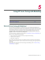
Chapter 5: Using RF Auto-Tuning with Modelling
What Is RF Auto-Tuning with Modelling? ....................................................................................................... 5-1
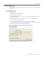
Add Site Information ....................................................................................................................................... 5-2
Adding Site information ............................................................................................................................ 5-2
Creating a Building ................................................................................................................................... 5-2
Adding a Floor to the Building .................................................................................................................. 5-3
Insert RF Obstacles ........................................................................................................................................ 5-5
Adding RF Obstacles ............................................................................................................................... 5-5
Create Your RF Coverage Area ..................................................................................................................... 5-6
Creating a Wiring Closet .......................................................................................................................... 5-6
Creating Your RF Coverage Area ............................................................................................................ 5-7
Add APs ................................................................................................................................................. 5-14
Associate APs to the Coverage Area ..................................................................................................... 5-14
What’s Next? ................................................................................................................................................ 5-15
Chapter 6: Using RF Planning
What is RF Planning? ..................................................................................................................................... 6-1
Prepare the Floor Drawings ............................................................................................................................ 6-2
Define Site Information ................................................................................................................................... 6-3
Create a Network Plan ............................................................................................................................. 6-3
Add Site Information ................................................................................................................................. 6-5
Create a Building ...................................................................................................................................... 6-6
Add a Floor to the Building ....................................................................................................................... 6-7
Import a Floor Plan ................................................................................................................................... 6-8
Import a Floor Drawing ....................................................................................................................... 6-8
Set the Scale ............................................................................................................................................ 6-9
Clean Layout ............................................................................................................................................ 6-9
Model RF Obstacles ..................................................................................................................................... 6-12
Import a Site Survey ..................................................................................................................................... 6-14
Plan RF Coverage ........................................................................................................................................ 6-14
Add Wiring Closets ................................................................................................................................. 6-14
Create Coverage Areas ......................................................................................................................... 6-15
Compute and Place APs ........................................................................................................................ 6-23
Assign Channel Settings ........................................................................................................................ 6-25
Calculate Optimal Power ........................................................................................................................ 6-26
Display Coverage ................................................................................................................................... 6-28
Generate a Work Order ................................................................................................................................ 6-28
Install the Equipment .................................................................................................................................... 6-29
What’s Next? ................................................................................................................................................ 6-30
xi
Chapter 7: Managing and Monitoring Your Network
What is Network Management? ..................................................................................................................... 7-1
What Is Network Monitoring? ......................................................................................................................... 7-1
Deploy Your Configuration ............................................................................................................................. 7-2
Immediately Deploying Local Changes .................................................................................................... 7-2
Scheduling Deployment of Local Changes .............................................................................................. 7-3
Verifying the Deployment ......................................................................................................................... 7-3
Accessing the Log .................................................................................................................................... 7-3
Perform Basic Administrative Tasks ............................................................................................................... 7-4
Configuring RoamAbout Switch Management Services .......................................................................... 7-4
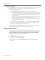
Distributing System Images ............................................................................................................................ 7-6
Using the Image Repository ..................................................................................................................... 7-6
Adding a System Image ..................................................................................................................... 7-6
Deleting a System Image ................................................................................................................... 7-6
Distributing System Images ..................................................................................................................... 7-7
Immediately Install an Image on RoamAbout Switches ..................................................................... 7-7
Schedule Installation of an Image on RoamAbout Switches .............................................................. 7-7
Saving Versions of Network Plans ........................................................................................................... 7-9
Saving a Version of a Network Plan ...................................................................................................7-9
Saving Network Plans Automatically .................................................................................................. 7-9
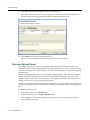
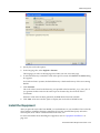
Importing and Exporting Switch Configuration Files ..................................................................................... 7-10
Importing a Configuration ....................................................................................................................... 7-10
Exporting a Configuration ....................................................................................................................... 7-11
Monitoring Examples .................................................................................................................................... 7-12
Monitor an Individual User ..................................................................................................................... 7-13
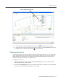
Finding the User ............................................................................................................................... 7-13
Locating the User ............................................................................................................................. 7-14
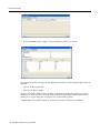
Displaying User Activity .................................................................................................................... 7-15
Viewing User Performance Statistics ............................................................................................... 7-17
Monitor a Group of Users ....................................................................................................................... 7-17
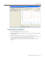
Viewing Performance Statistics for an Individual Radio ................................................................... 7-17
Viewing RF Trends for an Individual Radio ......................................................................................7-19
What’s Next? ................................................................................................................................................ 7-20
Chapter 8: Managing Alarms
What Is Fault Management? .......................................................................................................................... 8-1
Set Up the Fault Management System ........................................................................................................... 8-1
Classify and Organize Faults .......................................................................................................................... 8-3
Search Capabilities .................................................................................................................................. 8-3
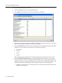
Manage Faults ................................................................................................................................................ 8-4
Alarm Summary ....................................................................................................................................... 8-5
Alarm Summary Details ...................................................................................................................... 8-5
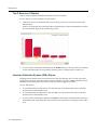
Top 5 Sources of Alarms .......................................................................................................................... 8-6
Intrusion Detection System (IDS) Alarms ................................................................................................. 8-6
Denial of Service (DoS) Alarms ............................................................................................................... 8-7
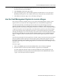
Store Faults and Retrieve Fault History .......................................................................................................... 8-7
Retrieving Fault History ............................................................................................................................ 8-7
Generate Alarm Reports ................................................................................................................................. 8-9
Alarm Summary Report ............................................................................................................................ 8-9
Alarm History Report .............................................................................................................................. 8-10
Security and Client OUI Reports ............................................................................................................ 8-10
Use the Fault Management System to Locate a Rogue ............................................................................... 8-11
Configuring Countermeasures.......................................................................................................... 8-14
What’s Next? ................................................................................................................................................ 8-17
xii
Chapter 9: Optimizing a Network Plan
Using RF Measurements from an Ekahau Site Survey .................................................................................. 9-2
Generating an Ekahau Site Survey Work Order ...................................................................................... 9-2
Importing RF Measurements from the Ekahau Site Survey ..................................................................... 9-4
Optimizing the RF Coverage Model ............................................................................................................... 9-6
Locating and Fixing Coverage Holes .............................................................................................................. 9-8
Displaying the RF Coverage Area ............................................................................................................ 9-8
Locking Down APs ................................................................................................................................... 9-9
Fixing a Coverage Hole ............................................................................................................................ 9-9
Computing and Placing New APs ............................................................................................................ 9-9
Replanning Your Network ........................................................................................................................ 9-9
What’s Next? ................................................................................................................................................ 9-10
Chapter A: Access Point 3000 Conversion
Preparing Deployed AP3000s for Conversion ................................................................................................A-1
Obtaining the Image .......................................................................................................................................A-2
Configuring the AP3000 .................................................................................................................................A-2
Returning to Standalone Mode .......................................................................................................................A-6
Chapter B: Access Point RBT-4102 Conversion
Preparing Deployed RBT-4102s for Conversion ............................................................................................B-1
Obtaining the Image .......................................................................................................................................B-2
Configuring the RBT-4102 ..............................................................................................................................B-2
Returning to Standalone Mode .......................................................................................................................B-5
Index
xiii
xiv
Introducing the Enterasys Networks Mobility System
This guide provides information about planning, configuring, deploying, and managing an Enterasys Networks Mobility System Wireless LAN (WLAN) using the RoamAbout Switch Manager (RASM) tool suite. Read this guide if you are a network administrator or a person responsible for managing a WLAN.
Enterasys Networks Mobility System
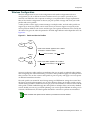
The Enterasys Networks Mobility System is an enterprise‐class WLAN solution that seamlessly integrates with an existing wired enterprise network. The Enterasys system provides secure connectivity to both wireless and wired users in large environments such as office buildings, hospitals, and university campuses and in small environments such as branch offices. The Enterasys Networks Mobility System fulfills the three fundamental requirements of an enterprise WLAN: It eliminates the distinction between wired and wireless networks, allows users to work safely from anywhere (secure mobility), and provides a comprehensive suite of intuitive tools for planning and managing the network before and after deployment, greatly easing the operational burden on IT resources.
The Enterasys Networks Mobility System consists of the following components:
•
RoamAbout Switch Manager tool suite—A full‐featured graphical user interface (GUI) application used to plan, configure, deploy, and manage a WLAN and its users
•
One or more RoamAbout® switches—Distributed, intelligent machines for managing user connectivity, connecting and powering access points, and connecting the WLAN to the wired network backbone
•
Multiple access points—Wireless access points (APs) that transmit and receive radio frequency (RF) signals to and from wireless users and connect them to a RoamAbout switch
•
Mobility System Software (MSS)—The operating system that runs all RoamAbout switches and access points in a WLAN. MSS is accessible through a command‐line interface (CLI), the WebView interface, or the RASM GUI
Documentation
Consult the following documents to plan, install, configure, and manage an Enterasys Networks Mobility System.
Planning, Configuration, and Deployment
RoamAbout Switch Manager User’s Guide. Instructions for planning, configuring, deploying, and managing the entire WLAN with the RASM tool suite. Read this guide to learn how to plan wireless services, how to configure and deploy Enterasys equipment to provide those services, and how to optimize and manage your WLAN.
RoamAbout Switch Manager Interface Reference Guide. Detailed instructions and information for all RASM planning, configuration, and management features. RoamAbout Switch Manager User’s Guide
xv
Installation
•
Regulatory Information. Important safety instructions and compliance information that you must read before installing Enterasys Networks products
•
RoamAbout Access Point Installation Guide. Instructions and specifications for installing an access point and connecting it to a RoamAbout switch
•
RoamAbout Switch Installation Guide. Instructions and specifications for installing a RoamAbout switch in an Enterasys Mobility System WLAN, and basic instructions for deploying a secure IEEE 802.11 wireless service
•
RoamAbout Mobility System Software Quick Start Guide. Instructions for performing basic setup of secure (802.1X) and guest (WebAAA™) access, and for configuring a Mobility Domain for roaming
Configuration and Management
•
RoamAbout Switch Manager Interface Reference Guide. Instructions for planning, configuring, deploying, and managing the entire WLAN with the RASM tool suite
•
RoamAbout Mobility System Software Configuration Guide. Instructions for configuring and managing the system through the MSS CLI
•
RoamAbout Mobility System Software Command Line Reference. Functional and alphabetic reference to all MSS commands supported on RoamAbout switches and access points
Safety and Advisory Notices
The following kinds of safety and advisory notices appear in this document. Note: This information is of special interest.
Caution: This situation or condition can lead to data loss or damage to the product or other
property.
Text and Syntax Conventions
Enterasys manuals use the following text and syntax conventions: xvi
Convention
Use
Monospace text
Sets off command syntax or sample commands and system responses.
Blue text
Indicates a hyperlink.
Bold text
Highlights commands that you enter, or items you select.
Italic text
Designates command variables that you replace with appropriate values, or
highlights publication titles or words requiring special emphasis.
Menu Name > Command
Indicates a menu item that you select. For example, File > New indicates
that you select New from the File menu.
[ ] (square brackets)
Enclose optional parameters in command syntax.
Introducing the Enterasys Networks Mobility System
Convention
Use
{ } (curly brackets)
Enclose mandatory parameters in command syntax.
| (vertical bar)
Separates mutually exclusive options in command syntax.
Getting Help
For additional support related to the product or this document, contact Enterasys Networks using one of the following methods:
World Wide Web
http://www.enterasys.com/services/support/
Phone
1-800-872-8440 (toll-free in U.S. and Canada) or 1-978-684-1000
For the Enterasys Networks Support toll-free number in your country:
http://www.enterasys.com/services/support/contact/
Internet mail
[email protected]
To expedite your message, please type [RoamAbout] in the subject line.
To send comments concerning this document to the Technical Publications Department:
[email protected]
To expedite your message, please include the document Part Number in the email message.
To expedite your service request, have the following information available when you call or write to GTAC for technical assistance:
•
Your Enterasys Networks service contract number
•
A description of the failure
•
A description of any action(s) already taken to resolve the problem (for example, changing mode switches or rebooting the unit)
•
The serial and revision numbers of all involved Enterasys Networks products in the network
•
A description of your network environment (such as layout, cable type, other relevant environmental information)
•
Network load and frame size at the time of trouble (if known)
•
The device history (for example, if you have returned the device before, or if this a recurring problem)
•
Any previous Return Material Authorization (RMA) numbers
•
Name, model, and serial number of the product(s) requiring service
•
Software version and release number
•
Output of the show tech‐support command
•
Wireless client information
•
License levels for RASM and RoamAbout Switch products
RoamAbout Switch Manager User’s Guide
xvii
xviii
Introducing the Enterasys Networks Mobility System
1
Getting Started
This section contains information about recommended system requirements you should meet for optimum RoamAbout Switch Manager (RASM) performance, installing RASM client and RASM Services software, and an introduction to using the RASM interface.
For information about...
Refer to page...
Hardware Requirements for RASM Client
1-1
Hardware Requirements for RASM Services
1-2
Preparing for Installation
1-4
Installing RASM
1-7
RASM Interface
1-13
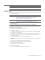
Hardware Requirements for RASM Client
Table 1‐1 lists the minimum and recommended requirements to run the RASM client on Windows and Linux platforms.
Table 1-1
Systems
Hardware Requirements for Running RASM Client on Windows and Linux
Minimum
Recommended
Processor
Intel Pentium 4 2 GHz or equivalent
Intel Pentium 4 3 GHz or equivalent
RAM
512 MB
1 GB
Hard drive space available
100 MB
200 MB
Monitor resolution
1024x768 pixels, 24-bit color
1600x1200 pixels, 32-bit color
CD-ROM drive
CD-ROM or equivalent
CD-ROM
RoamAbout Switch Manager User’s Guide
1-1
Hardware Requirements for RASM Services
Table 1‐2 shows the minimum requirements to run the RASM client on the Sun Solaris platform.
Table 1-2
Hardware Requirements for Running RASM Client on Solaris Systems
Minimum
Recommended
Processor
Sun UltraSPARC 10 or equivalent
Sun Blade 150, or equivalent
RAM
1 GB
2 GB
Hard drive space available
100 MB
200 MB
Monitor resolution
1024x768 pixels, 24-bit color
1600x1200 pixels, 32-bit color
CD-ROM drive
CD-ROM or equivalent
CD-ROM
Table 1‐3 shows the minimum and recommended requirements to run the RASM client on Apple Macintosh platforms.
Table 1-3
Hardware Requirements for Running RASM Client on Apple Macintosh Systems
Minimum
Recommended
Processor
G3 or greater
G3 or greater
RAM
OS 10.4x: 128 MB
OS 10.4x: 128 MB
Hard drive space available
100 MB
200 MB
Monitor resolution
1024x768 pixels, 24-bit color
1600x1200 pixels, 32-bit color
CD-ROM drive
CD-ROM or equivalent
CD-ROM
Hardware Requirements for RASM Services
Table 1‐4 shows the minimum and recommended requirements to run the RASM Services on Windows and Linux platforms.
Table 1-4
Systems
1-2
Getting Started
Hardware Requirements for Running RASM Services on Windows and Linux
Minimum
Recommended
Processor
Intel Pentium 4 2.4 GHz or
equivalent
Intel Pentium 4 3.6 GHz or
equivalent
RAM
1 GB
2 GB
Hard drive space available
1 GB
2 GB
Monitor resolution
1024x768 pixels, 24-bit color
1600x1200 pixels, 32-bit color
CD-ROM drive
CD-ROM or equivalent
CD-ROM
Hardware Requirements for RASM Services
Table 1‐5 shows the minimum requirements to run the RASM Services on the Sun Solaris platform.
Table 1-5
Hardware Requirements for Running RASM Services on Solaris Systems
Minimum
Recommended
Processor
Sun UltraSPARC 10 or equivalent
Sun UltraSPARC III or equivalent
RAM
1 GB
2 GB
Hard drive space available
1 GB
2 GB
Monitor resolution
1024x768 pixels, 24-bit color
1600x1200 pixels, 32-bit color
CD-ROM drive
CD-ROM or equivalent
CD-ROM
Table 1‐6 shows the minimum requirements to run the RASM Services on the Apple Macintosh platform.
Table 1-6
Systems
Hardware Requirements to Running RASM Services on Apple Macintosh
Minimum
Recommended
Processor
G3 or greater
G3 or greater
RAM
1 GB
2 GB
Hard drive space available
1 GB
2 GB
Monitor resolution
1024x768 pixels, 24-bit color
1600x1200 pixels, 32-bit color
CD-ROM Drive
CD-ROM or equivalent
CD-ROM
RoamAbout Switch Manager User’s Guide
1-3
Software Requirements
Software Requirements
RASM client and RASM Services are supported on the following operating systems:
•
Microsoft Windows Server 2003, Microsoft Windows XP with Service Pack 1 or higher, or Microsoft Windows 2000 with Service Pack 4 •
Sun Solaris 8 and Solaris 9 •
SUSE Linux 9.1 and Red Hat WS 3
•
Apple Macintosh OS 10.4x with Java 1.5
Note: You must use the English version of the operating system you select. Operating system
versions in other languages are not supported with RASM.
The following additional software is required for certain RASM features:
•
HP OpenView Network Node Manager 6.4—Must be installed prior to RASM if you plan to use RASM in your HP OpenView environment.
•
Adobe Acrobat Reader 5.x or later (or plug‐in)—For reading the RoamAbout Switch Manager Interface Reference and release notes.
•
Web browser (for example, Microsoft Internet Explorer 5.x or 6.x, or Netscape Navigator 6.x or 7.x)—For displaying RASM Help, work orders and inventory reports. Preparing for Installation
Before you install RASM, make sure you have the appropriate administrative privileges on the system, a serial number, and a license key if required. If you plan to install the HP OpenView plug‐in for RASM, which allows you to integrate RASM into an HP OpenView environment, make sure that HP OpenView is already installed.
User Privileges
Before you install RASM, make sure that you are logged in as a user who has permission to install software, or logged in as an administrator. If you are installing on a UNIX or Linux platform, you must log on with root privileges. After you install RASM, you can configure RASM access privileges for the user accounts on the machine. Likewise, you can configure access privileges for RASM Services, if installed. Access privileges for the RASM client are completely independent of access privileges for the monitoring service, and are configured separately. 1-4
Getting Started
Preparing for Installation
Serial Number and License Key
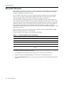
The serial number is included with your RASM software packaging. You must request a license key from Enterasys Networks for each host on which you plan to use site planning or monitoring. One license allows you to use RASM planning or install the monitoring service on one system. Depending on the license, you might also have restrictions on the number of access points you can manage using RASM.
You can use the serial number and a valid host name to request license keys for the following types of licenses:
•
RF Planning—Enables the RF modelling features of planning. With an RF Planning license, you can create RF obstacles, compute and place equipment, assign radio channels, and optimize radio power settings. Without an RF Planning license, you still can import or create floor plans and create coverage areas. •
RASM Services—Enables you to install RASM Services (the RASM server). When requesting a license key, you must provide your serial number and the hostname of the system on which RASM is to be installed. You must also indicate the feature(s) for which you want to have a license. Specify the host name of the host where the client (for RF Planning) or server (for RASM Services) will be installed. The host name you provide when you request the key must match the host name on the host where you install the product.
Depending on the license, you might also have restrictions on the number of RoamAbout Access Points you can manage using RASM. Enterasys Networks recommends that you request a license key through RASM after installation. If that is not possible, you can contact the Enterasys Networks Technical Assistance Center (TAC). (Refer to “Getting Help” on page xvii.)
HP OpenView Network Node Manager
If you already have an HP OpenView environment and want to integrate RASM into this environment, you have the option of installing the HP OpenView plug‐in required to use Network Node Manager with RoamAbout Switch Manager. Make sure that HP OpenView is already installed before installing RASM with the plug‐in.
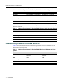
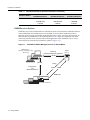
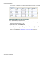
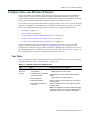
Resource Allocation
Table 1‐7 contains general recommended guidelines for hardware requirements and memory allocation based on the number of radios and RoamAbout switches your server will support. A larger number of RoamAbout switches suggests more connections and data processing, which will require more CPU power. A larger number of radios suggests more data (including client sessions) which requires more RAM and storage.
Table 1-7
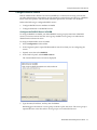
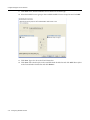
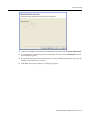
Recommended Server Hardware Allocation
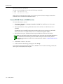
Number of Radios
1-25
RoamAbout Switches
25-50
RoamAbout Switches
50+
RoamAbout Switches
1 – 1000
2.4 MHz P4
2.8 MHz P4
3.2 MHz Xeon
500 MB RAM
500 MB RAM
1 GB RAM
1 GB HD
1 GB HD
1 GB HD
RoamAbout Switch Manager User’s Guide
1-5
Preparing for Installation
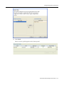
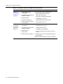
Table 1-7
Recommended Server Hardware Allocation (continued)
Number of Radios
1-25
RoamAbout Switches
25-50
RoamAbout Switches
50+
RoamAbout Switches
1000 – 2000
2.4 MHz P4
3.0 GHz P4
3.6 GHz Xeon
1000 MB RAM
1000 MB RAM
2 GB RAM
2 GB HD
2 GB HD
2 GB HD
RASM Services Options
RASM Services can be installed either in standalone mode or shared mode. Standalone mode is when RASM client and RASM Services are installed on one machine. Standalone mode is primarily used for trying out RASM, while shared mode is used in a working environment. In shared mode, the administrator sets up RASM Services on a single host (typically with more resources) and other hosts with the client RASM application share RASM Services to access network plans and monitoring information. (Refer to Figure 1‐1).
Figure 1-1
RoamAbout Switch Manager Services in Shared Mode
RASM Clients -Planning, Configuration and
Monitoring
Data from
Planning and Monitoring Services
HTTPS
HTTPS
Configuration
and
Monitoring Services
Polling
HTTPS
SNMP
SNMP Traps
Rst
Rst
Rst
Console
Console
Console
RoamAbout Switches
1-6
Getting Started
RASM
Services
Installing RASM
Installing RASM
The RASM installation program installs either RASM client, RASM Services, or both. This section contains information about the following topics:
•
“Using the Installation Wizard” on page 1‐8
•
“RASM Access Control” on page 1‐12
Unpacking Files
Windows
To unpack files on Windows systems:
1.
Insert the RASM CD into the CD‐ROM drive. If Autorun is enabled, wait briefly for the installation program to start. For more information about using the installation wizard, see “Using the Installation Wizard” on page 1‐8. If Autorun is disabled, follow these steps:
2.
a.
In Windows Explorer, navigate to your CD‐ROM drive.
b.
In the Windows\VM directory, double‐click install.exe. The Introduction page of the RASM installation wizard appears.
Click Next to display the Choose Installation Type page of the installation wizard, and go to “Using the Installation Wizard” on page 1‐8. UNIX and Linux
To unpack files on UNIX and Linux systems:
1.
Log in as superuser.
2.
Insert the RASM CD into the CD‐ROM drive.
3.
For the platform on which you are installing RASM, click the appropriate Installer link. 4.
Save the installation binary to a directory.
5.
Open a shell window.
6.
Use the cd command to go to the directory in which you saved the installation binary.
7.
In the shell window, type sh ./install.bin. The Introduction page of the RASM installation wizard appears.
8.
Click Next to display the Choose Installation Type page of the installation wizard, and go to “Using the Installation Wizard” on page 1‐8.
Apple Macintosh
To unpack files on Apple Macintosh systems:
1.
Insert the RASM CD into the CD‐ROM drive.
2.
Double‐click the RASM CD icon.
3.
Click Continue, then follow the on screen instructions to install the RASM software.
RoamAbout Switch Manager User’s Guide
1-7
Installing RASM
4.
When the installation is complete, restart the computer.
The installer does not make any path changes during installation. You might want to configure path information, to make RASM easy to start on your system. RASM must be run at the root level. Using the Installation Wizard
To use the installation wizard:
1.
On the Choose Installation Type page, select one of the following:
•
To install both the RASM server and the client, click the RASM Services icon.
•
To install only the RASM client, click the RASM client icon.
Note: For detailed installation instructions, see “Installing RASM” in the RoamAbout Switch
Manager Interface Reference.
2.
Near the end of the installation process, the installer displays the following service ports that RASM Services will use:
•
443—HTTPS server port
•
162—SNMP trap receiver port
You can change one or both port numbers to prevent conflicts with other applications on the same host.
Notes:
• Multiple applications cannot use the same UDP or TCP port on the same host. For example, port
443 is defined by the Internet Assigned Numbers Authority (IANA), as the well-known HTTPS
port. If the host on which you install RoamAbout Switch Manager Services uses its default
HTTPS port (443), and the same host also runs Microsoft Internet Information Services (IIS) on
its default HTTPS port (443), there will be a conflict over the port. RoamAbout Switch Manager
clients will not be able to communicate with RoamAbout Switch Manager Services.
• If you plan to use the remote configuration option to configure new switches, you must use port
443 for RoamAbout Switch Manager Services. When a switch requests its configuration from
RoamAbout Switch Manager Services, it sends the request to port 443.
Starting RASM Services
The method to start monitoring service depends on the platform on which the service is installed: 1-8
•
Windows systems—RASM Services are started automatically when you complete installation and starts automatically whenever you restart your system. •
Linux and UNIX systems—You can start and stop the RASM Services manually from the command line using a shell script that is installed when you install RASM Services. You also can configure the RASM Services to start and stop automatically.
•
Macintosh systems—RASM Services are not started automatically; you must start them manually.
Getting Started
Installing RASM
Start the RASM Services on a Unix or Linux System
To start RASM Services manually, type a command such as the following:
solaris# rm-services start
Stop the RASM services on a UNIX or Linux System
To stop RASM Services manually, type a command such as the following:
solaris# rm-services stop
Configure RASM Services as a daemon
The following examples assume that RASM Services is installed in the default location.
Configure RASM Services as a daemon on Solaris
To configure RASM Services to start automatically when Solaris starts, type the following command:
solaris# ln -s /opt/RASM/bin/rm-services /etc/rc3.d/S99rm-services
Make rm‐services the last script that runs at run level 3.
To configure RASM Services to stop automatically when Solaris shuts down, type the following command:
solaris# ln -s /opt/RASM/bin/rm-services /etc/rc0.d/K99rm-services
Make rm‐services the last script that runs at run level 0.
Configure RASM Services as a daemon on SUSE 9.1
The recommended way to add services to a SUSE 9.1 installation is with the insserv command. Enter commands such as the following (as root):
suse# cd /etc/init.d
suse# ln -s /opt/RASM/bin/rm-services rm-services
suse# insserv rm-services
Configure RASM Services as a daemon on Red Hat WS 3
The recommended way to add services to a Red Hat WS 3 system is with the chkconfig command. Enter commands such as the following (as root):
redhat# cd /etc/init.d
redhat# ln -s /opt/RASM/bin/rm-services rm-services
redhat# chkconfig --add rm-services
To Start/Stop RASM Services on Macintosh Systems
To start RASM Services manually, open a Terminal window, either by using the shortcut on the dock, or by browsing to the /Applications/Utilities directory and launching Terminal from there.
In the Terminal window, change to the bin directory in the RASM installation directory. By default, this is /Applications/RASM/bin. For example:
# cd /Applications/RASM/bin
To start RASM Services, enter the following command:
# sudo ./rm-services start
RoamAbout Switch Manager User’s Guide
1-9
Installing RASM
Enter the password, if prompted.
To stop or restart RASM Services, enter the following commands:
# sudo ./rm-services stop
# sudo ./rm-services restart
Either of these commands may require you to enter a password. These examples assume that RASM Services is installed in the default location.
Connect RASM Clients to RASM Services
To connect the client to services:
1.
Select Start > Programs > Enterasys Networks > RASM. The RASM Services Connection wizard is displayed.
2.
Enter the IP address or fully‐qualified hostname of the machine on which the service is installed. If RASM Services is installed on the same machine as the one you are using to run RASM client, enter 127.0.0.1 as the IP address. This is a standard IP loopback address. 3.
Specify the service port, if different from the port number in the Service Port list box. Note: The port number used by the monitoring service must not be used by another application on
the machine where the monitoring service is installed. If the port number is used by another
application, change the port number on the monitoring service. (Refer to Configure RASM Services
on page 1-11.)
4.
Click Next to connect to the server.
5.
If the Certificate Check dialog is displayed, click Accept.
If you left the Open Network Plan option on the RASM Services Connection dialog selected, the server opens a new (blank) network plan. 1-10
Getting Started
Installing RASM
Configure RASM Services
You can change the properties of RASM Services.
Note: If a firewall is enabled on the host where you install RASM Services, RASM Services will not
be able to communicate with RASM client or with RoamAbout switches unless the firewall is
configured to allow through traffic for the SSL and SNMP ports (443 and 162 by default).
To configure RASM Services:
1.
Select Services > Setup. RASM Services will open in your default browser
Note: By default, a username and password are not required to access RASM Services from RASM
client. You can configure user accounts for administrative, provisioning, and monitoring access.
(Refer to “RASM Access Control” on page 1-12.)
2.
Configure the following options by clicking Server Settings on the left of the browser window:
•
Enter the desired HTTPS Server Port in the HTTPS Server Port field. The HTTPS Server Port is the port on which RASM Services listens for requests from RoamAbout Switch Manager client.
•
Enter the desired HTTP Server Port in the SNMP field. The SNMP Server Port is the port on which SNMP traps are received. Select the trap type from which you want RoamAbout Switch Manager Services to receive RoamAbout Switches, SNMPv1 or SNMPv3.
Notes: On each switch in the network plan, you must enable notifications and configure
RoamAbout Switch Manager Services as a notification target (trap receiver).
RoamAbout Switch Manager Services does not start listening for SNMP notifications from switches
until you save the network plan.
RoamAbout Switch Manager User’s Guide
1-11
Installing RASM
•
From the Key Store area of the window, specify security settings.
The Auto‐Config IP Subnet Matching option is used for field replacement of RoamAbout Switches. For information, refer to “Configuring RoamAbout Switches Remotely” in the RoamAbout Switch Manager Interface Reference Guide.
Click Access Control on the left to define user accounts. For more information about access control, refer to “RASM Access Control” on page 1‐12.
Monitoring Settings
All monitoring options are enabled by default. You do not need to enable them and you do not need to specify the switches you want to monitor. However, for RASM Services to receive trap data from RoamAbout switches, SNMP notifications must be enabled on the switches.
To start gathering data for monitoring, deploy your configuration to the network. For information about deploying your configuration, refer to “Deploy Your Configuration” on page 7‐2.
RASM Access Control
You can create a user account with administrator, provision, or monitor privileges. Refer to Table 1‐8 for privilege definitions. For details, refer to “Restricting Access to RASM” in the “Getting Started” section of the RoamAbout Switch Manager Interface Reference Guide. Table 1-8
User Privilege Levels
Privilege Level
Access Control
Configuration
Monitoring
Administrator
yes
yes
yes
Provision
no
yes
yes
Monitor
no
no
yes
To configure access control:
1-12
1.
Select Services > Setup from the RASM main toolbar. RASM Services is displayed in your default Web browser. 2.
Select Access Control in the left pane.
3.
Click Enable login‐required. Enter a username and password for administrative access. Click OK. (You must configure an admin account before you can configure provisioning or monitoring users.)
4.
Enter the name under the Add User section. 5.
Select Administrator, Provisioning User, or Monitoring User in the Role field.
6.
Enter the password. Re‐enter the password.
7.
Click Save. The new account will appear in the Authorized Users section.
8.
To remove an account, click Delete.
9.
To reset a password, click Edit.
Getting Started
RASM Interface
RASM Interface
This section contains the following topics:
•
“Display the Main Window” on page 1‐13
•
“Using the Toolbar and Menu Bar” on page 1‐14
•
“Setting Preferences” on page 1‐14
•
“Easy Configuration Using Wizards” on page 1‐15
•
“Easy Configuration Using Wizards” on page 1‐15“Easy Configuration Using Wizards” on page 1‐15
Display the Main Window
When you start RASM client and log onto RASM Services, a network plan is displayed by the RASM client (see Figure 1‐2 on page 1‐14):
•
The Organizer panel displays a network tree representing your WLAN’s devices and configurations on those devices. You can use it to navigate to Policy configurations, equipment within your network, and network Sites.
•
When you select a device or configuration in the tree, the context‐sensitive information about the device or configuration is displayed to the right in the Content and Information panels. •
The Content panel displays context‐sensitive information about the device or configuration selected from the tree in the Organizer panel. From the Content panel, view Enterasys devices and their status, verify Enterasys device configurations in the network plan and in the network, and display event logs and Rogue detection results.
•
The Alerts panel displays a summary of alerts, including network and configuration verification, Rogue detection, and local and network changes. Click on a summary to display details.
•
The Task Panel displays additional context‐sensitive options related to your toolbar selection.
The Server icon indicates the status of the connection between the RoamAbout Switch Manager client and the host running RoamAbout Switch Manager Services.
RoamAbout Switch Manager User’s Guide
1-13
RASM Interface
Figure 1-2
RASM Main Window
Organizer panel
Content panel
Task panel
Toolbar
Alerts panel
Server Icon
Using the Toolbar and Menu Bar
The main RASM window has a toolbar that provides quick access to features and summary views. You can use the Back and Forward buttons to cycle through your display selections.
The menu bar (located above the toolbar) provides access to administrative options such as plan management and access to online help. For example, to examine recent activity, select
Tools > Events.
Setting Preferences
You can set network, user interface, save interval and autosave, certificate handling, RF monitoring, and logging.
1.
Select Tools > Preferences from the RASM main toolbar.
The Preferences wizard is displayed.
1-14
Getting Started
RASM Interface
2.
Select any of the tabs, make modifications in the fields, and select Reset All to reset preferences.
Easy Configuration Using Wizards
Wizards help walk administrators through configuration steps. There are many wizards in the RASM application. Enter the required fields and click Next at the bottom of the wizard to display the next step. Click Cancel to discard any changes made with the wizard. When you are done, click Finish or OK to save changes. You can right‐click (Macintosh: Control+click) on many objects to display the Insert option. Select Insert to create a new object that is a “child” of the selected object.
RoamAbout Switch Manager User’s Guide
1-15
RASM Interface
Getting Help
Click Help from the Main menu bar to access online help and other information:
1-16
1.
Select Help > Help to display HTML help about configuring and using RASM.
2.
Select Services > Licensing to open a browser window and view product licensing information, or to get access to Enterasys Networks product licensing server web page.
3.
Select Help > Report Problem to report a problem to Enterasys Technical Support.
4.
Select Help > About RASM to display information about RASM. You also can click Force GC (garbage collection) to free resources.
Getting Started
2
Planning and Managing Your Wireless Network
This section contains information about planning and managing your wireless network with RoamAbout Switch Manager (RASM). Planning your wireless network is highly recommended because it not only helps you configure and deploy it, but also aids in scaling and monitoring your network. Enterasys Networks provides you with flexible tools to assist with network planning.
For information about...
Refer to page...
Which Services to Provide?
2-2
Network Plan
2-2
RF Coverage Area
2-3
Configuration
2-6
Equipment Installation
2-12
Deployment
2-12
Management and Monitoring
2-13
RF Plan Optimization
2-17
Plan your wireless network to support the services you want to offer your employees, guests, or customers. Figure 2‐1 describes the process you will follow to establish services in your company or organization, beginning with determining the services you want to offer. Each step in the process is described in this section.
Figure 2-1
START
Process to Establish Wireless Services
Determine which
services to
provide
Configure
services
Optimize
services
Plan for network
equipment and
coverage
Generate work
order and install
equipment
Monitor
services
Deploy
services
RoamAbout Switch Manager User’s Guide
2-1
Which Services to Provide?
Which Services to Provide?
What is a service?: A service is a concept (not a selectable item in the RASM interface) that represents a set of options you configure and deploy on your wireless network. You configure services to support the different levels of network access you need to provide. For example, a service configured to support employee access will have different options configured to provide greater access to the network. In contrast, a service configured for guest access typically restricts users to limited or no internal network access, but easily provides a gateway connection to the Internet. A service can be fully isolated and independent of other services on the network (multi‐hosted access is typically isolated), or you can reuse part of a service configuration for another service you want to provide. Each service has potential authentications (802.1X, Web page, MAC address, or “last resort”) and potential encryptions (802.11i, WPA, WEP, or unencrypted).
Purpose of this section: To provide information about services that you can configure using RASM.
Why is this important?: Understanding the services you can configure with RASM is the first step in planning and configuring your network.
First, determine which services your organization requires. The three common types of services are as follows:
•
Employee access
•
Guest access
•
Voice over Wireless IP (VoWIP)
Employee access is typically secure, encrypted access to the wireless network. Guest access is access (possibly unencrypted) for visitors at your location. If you intend to resell services to other providers, you will need to provide multi‐hosted access.
Determining the services you will need at the beginning of the planning process results in configuration data. The configuration data is used to create service profiles and AAA rules for each service. A service profile is a subset of a radio profile. A radio profile is a common set of configuration parameters that can be applied to many AP radios.
Refer to “Create a Service Profile” on page 4‐3 for information about configuring services.
Network Plan
What is a network plan?: A network plan is the workspace in RASM you use to design a wireless network.
Why is this important?: You can better manage and visualize your network topology by creating a detailed and accurate network plan.
You can start by creating a device‐oriented (RoamAbout switches and APs) view of your network without any geographic information about your site—no floor dimensions, building material information, or RF obstacle information. You can go a step further and provide some geographic information by adding floor dimensions, your RF coverage area, and some attenuation information, such as elevator shafts or internal concrete walls. If you want to enjoy the full benefits of network monitoring and visualization, you can create a detailed network plan. This is done by importing detailed building and floor plans into RASM, defining RF obstacles, and defining the quality of coverage (traffic engineering parameters) you want for specific RF coverage areas. 2-2
Planning and Managing Your Wireless Network
RF Coverage Area
RF Coverage Area
What is an RF coverage area?: An RF coverage area is the geographical area in which IEEE 802.11 radios provide wireless services.
Purpose of this section: To describe the three techniques you can use for RF coverage.
Why is this important?: By understanding available RF coverage planning techniques, you can use the technique that meets your organization’s requirements.
There are three techniques you can use to start your wireless network:
•
RF Auto‐Tuning lets you use the default auto tuning feature to select power and channel settings for RF signals in your RF coverage area. You upload the RoamAbout switches into RASM, configure the APs, enable RF Auto‐Tuning, and deploy. •
RF Auto‐Tuning with Modelling, as with the RF Auto‐Tuning technique, lets you set the auto tuning feature to adjust power and channel settings to provide RF signals to the coverage area for your users. Enhance the auto tuning feature by providing modelling information about your geographic location. By providing some information about your buildings and floors, add enough details into RASM so that you can better visualize your network topology and support improved monitoring at your site. •
RF Planning is a technique you can use to create a detailed network plan that provides powerful monitoring and visualization benefits. Unlike RF Auto‐Tuning or RF Auto‐Tuning with Modelling, you do not rely on the auto tuning feature. Instead, you fully model your geographic location with detailed information about your floors, and specify your RF coverage areas and your RF obstacles. Each of these methods is described in the sections that follow.
RF Auto-Tuning
Perform the following steps to use the RF Auto‐Tuning technique:
1.
Physically place RoamAbout switches and the APs in their desired locations. 2.
Upload a RoamAbout switch configuration and deploy it.
3.
Enable the RF Auto‐Tuning feature.
This is a great way to install a RoamAbout switch and some APs, and observe how the network operates. The RF Auto‐Tuning plan is best suited to networks containing fewer APs.
RF Auto-Tuning with Modelling
To use the RF Auto‐Tuning with Modelling technique, you add to the RF Auto‐Tuning technique by providing some geographical modelling about your building, floors, and RF coverage area. You also add RF obstacle information for major obstacles (like concrete walls, windows, and elevator shafts) that affect attenuation—the quality of RF signals emitted from and received by the APs. By adding geographical modelling, you will be able to manage your network in the context of that geographical information. For example, you will be able to manage your network overlaid on a floor plan, versus managing an abstract logical group of switches and APs. RoamAbout Switch Manager User’s Guide
2-3
RF Coverage Area
RF Planning
To do RF Planning, you provide detailed information about your site and buildings by importing AutoCAD DXF™, AutoCAD DWG, JPEG, or GIF floor plan files of the buildings into RASM. As you import the floor plans, you can modify them to add or remove RF obstacles. You define RF obstacles by specifying the attenuation factor in decibels for the obstacle. In addition, RASM includes a library of attenuators for building obstacles. The library includes doors, walls, ceilings, and other physical obstructions that you can select. RASM factors in the impact these objects have on how the radio frequency (RF) signals flow through a given site.
If the network contains third‐party APs or pre‐installed APs, you can enter information for these APs so that RASM takes the APs into account when calculating the placement (and optionally, the channel and power settings) of the Enterasys APs. By using this technique, you receive the following benefits:
•
Instead of you making a “best guess” as to how many APs you require for the desired coverage and where APs should be placed, RASM automatically calculates how many APs you need and where to place APs for optimal positioning.
•
You can generate a deployable work order to help installers place RoamAbout switches and APs. •
You automatically receive a deployable configuration that includes optimum power and channel settings.
•
You enjoy more accurate monitoring options and network visualization based on the additional geographic modelling information loaded into RASM. Which Planning Method Should I Use?
The more detailed your network plan, the better you will be able to manage and monitor the network. However, there are other requirements that organizations should consider.
We suggest you use the RF Auto‐Tuning technique if you are installing APs without consideration to blanket coverage, throughput concerns, or the number of users for whom service will be provided. RF Auto‐Tuning is ideal for small areas; for example, coverage that only requires a few APs, or widely dispersed areas in a building, such as conference rooms.
Use the RF Auto‐Tuning with Modelling technique if you want to better monitor your wireless network in terms of buildings, floors, or coverage areas. You might be able to locate inaccurate or incomplete building and floor plans (perhaps only a JPEG file), but with even a bit more geographic modelling of your site, you boost your ability to manage and visualize your network. Use RF Planning when you want to use all the tools provided in RASM to deploy, manage, and monitor your network. You likely have multiple constituencies of users you need to consider; for example, sets of users that are mobile and wireless that have specific throughput and bandwidth needs. One group of users may be mobile and require high throughput performance (a higher bandwidth), while another group of users are more stationary and require less throughput. Additionally, you may be planning for future capacity, and need to add as much detailed information as you can about your site in order to plan for the future.
2-4
Planning and Managing Your Wireless Network
RF Coverage Area
Refer to Table 2‐1 for some guidelines to help you determine what planning technique is right for your organization.
Table 2-1
Planning Techniques to Use
Concern
If yes, use
If No, use
Do I have adequate time to add
geographic modelling and RF obstacle
information?
RF Auto-Tuning with Modelling
RF Auto-Tuning
Can I locate accurate building and
floor plans?
RF Planning or
RF Auto-Tuning with
Modelling
Do I need to plan for capacity of users
or quality of coverage (traffic
engineering concerns) for certain
users?
RF Planning
RF Auto-Tuning or RF
Auto-Tuning with Modelling
Do I need to visualize coverage
accurately?
RF Planning
RF Auto-Tuning or RF
Auto-Tuning with Modelling
Do I need to locate users?
RF Planning or RF Auto-Tuning with
Modelling
RF Auto-Tuning
Do I need to locate rogue APs?
RF Planning or RF Auto-Tuning with
Modelling
RF Auto-Tuning
Do I want to better monitor my wireless
network in terms of buildings, floors, or
coverage areas?
RF Planning or RF Auto-Tuning with
Modelling
RF Auto-Tuning
RF Auto-Tuning with Modelling
If RF Planning does not fit your requirements now, you can always use the RF Planning technique in the future when you have the need, the time, and the necessary floor plans available. You also can leverage the data in RF Auto‐Tuning and convert these RF measurements to configured baseline values for planning.
RoamAbout Switch Manager User’s Guide
2-5
Configuration
Configuration
Purpose of this section: To describe the main areas of the Enterasys Network (RoamAbout switch and DAPs) you will configure in RASM.
Why is this important?: To provide you with overview information about the software so that you can plan a configuration to support the services you require.
You will configure the wireless configuration and AAA security configuration for each service you provide on your wireless network. You also create a basic configuration for the RoamAbout switch. Figure 2-2
Configuration Required for Each Service
Wireless Service
Wireless Configuration
- Radio Profile
- Service Profile
- Encryption Choices
AAA Security Configuration
- AAA methods
- Rules
- Authentication choices
This section contains the following information:
2-6
•
“Wireless Configuration” on page 2‐7
•
“AAA Security Configuration” on page 2‐8
•
“System and Administration Configuration” on page 2‐10
Planning and Managing Your Wireless Network
Configuration
Wireless Configuration
Wireless configuration focuses on the configuration tasks (radio configuration and AAA configuration) you do to deliver the virtual wireless services you want to provide on your network. You enable the APs to operate according to your planned RF coverage requirements. Most of the wireless configuration is done as you plan your RF coverage and create your radio profiles and service profiles.
A radio profile is used to apply common settings to multiple radios, and each radio profile can support up to 32 service profiles, one for each service you want to support. You specify in the service profile an SSID for each service and the type of encryption mechanisms to be used by the AP radios. This gives the radio the potential to look like eight different and independent APs. See Figure 2‐3.
Figure 2-3
Radio and Service Profiles
Radio 1
AP 1
Radio 2
Radio 1
Radio Profile “default” applied to AP 1, Radio 1
and Radio 2 and AP 2, Radio 1
Service Profiles, 1-32
SSID
AP 2
Radio 2
Radio Profile “EBC” applied to AP 2, Radio 2
Service Profiles, 1-32
SSID
You must configure a radio profile to set attributes that you can apply to multiple radios. Rather than configuring each radio individually, you create a radio profile and apply it to multiple radios that you select. You can also create a radio profile as part of a policy and apply it to access points on different RoamAbout switches.
The radio profile can contain RF Auto‐Tuning settings and IEEE 802.11 settings that control how the data is received and transmitted. You can select RF Auto‐Tuning in the radio profile to apply AutoRF settings (enable or disable auto tuning of power and channels) to radios en masse via the radio profile. AutoRF enabled through the radio profile to multiple radios can be easily disabled as well, should you want to go to full RF planning. You can set specific IEEE 802.11 settings, such as beacon, DTIM intervals, and the fragment threshold to control how packets are transmitted. Note: A default radio profile named “default” is provided and cannot be deleted.
RoamAbout Switch Manager User’s Guide
2-7
Configuration
For each service you want to provide, you configure the following items in a service profile:
•
The SSID name
•
SSID advertisement (whether the SSID name is beaconed)
•
Whether the SSID name is encrypted or clear (not encrypted)
•
Web page (if using WebAAA)
•
Multiple encryption choices (Dynamic/static WEP, WPA, WEP + WPA, 802.11i)
Note: You also must configure AAA security configuration items for each service. For more
information, see “AAA Security Configuration” on page 2-8.
The encryption you use depends on the type of services you are offering. Employee access is typically encrypted, guest access is typically clear (no encryption), and multi‐host or “multiple virtualized services” service can be encrypted, with each SSID being matched with its own service profile. If services are being used for customer corporate entities (e.g. different airlines on an airport wireless net), then they would probably use 802.1X and strong encryption with web guest access for their airport club guests. If the services are being used to advertise multiple wireless service providers (WISP), such as T‐MobileTM, Wayport ®, and Boingo WirelessTM, then these services would probably be completely open. However, they would likely be assigned to their own dedicated subnet containing their proxy server/billing gateway.
AAA Security Configuration
An administrator can control the way in which users access the network. For each service you provide, you can configure unique authentication, authorization, and accounting (AAA) security features, creating an entirely virtualized wireless service. For each service, you configure the following items:
•
Multiple authentication choices (802.1X, Web, AAA, MAC authentication, Bonded Auth, open)
•
AAA methods (up to four RADIUS server groups, or a local database on the RoamAbout switch)
Authentication
Authentication is the method of determining whether a user is allowed access to your network. Users can be authenticated by a RADIUS server (pass‐through) or by the RoamAbout switch local database (local). The RoamAbout switch can also assist the RADIUS server by performing the Extensible Authentication Protocol (EAP) processing for the server (offload).
To authenticate users, you will need to configure users either in the local database or on RADIUS servers. Each user will have a username, password, and RADIUS and/or vendor‐specific attributes (VSAs). You will also need to configure authentication rules (802.1X, MAC, last‐resort, or web authentication).
Figure 2‐4 on page 2‐9 shows a flowchart representing the authentication process. Generally, 802.1X authentication is attempted first. If the user fails, then MAC authentication is attempted. If this fails, then last resort and web authentication is used. For a service profile, you specify either web authentication, last‐resort, or none in the auth‐fall‐thru box. You can only select one.
2-8
Planning and Managing Your Wireless Network
Configuration
Figure 2-4
Authentication Flowchart for Network Users
Client associates with Enterasys radio
Client requests
encrypted SSID?
Yes
802.1X rule that
matches SSID?
Client
responds
to 802.1X?
Yes
No
Yes
No
Authent.
Allow
succeeds? Yes Client
No
No
Refuse
Client
Authent.
Allow
succeeds? Yes Client
MAC rule that
matches SSID?
No
No
Use fallthru authentication
Last-resort rule that
matches SSID?
last-resort?
Yes
No
Yes
No
none?
Yes
No
No
Refuse
Client
Refuse
Client
Web Auth rule that
matches SSID?
web?
Yes
Authent.
Allow
succeeds? Yes Client
Yes
Authent.
Allow
succeeds? Yes Client
No
No
Refuse
Client
Refuse
Client
Refuse
Client
RoamAbout Switch Manager User’s Guide
2-9
Configuration
Authorization
Authorization is the method for providing users with specific rights to the network by associating attribute‐value (AV) pairs to the user. AAA authorization works by assembling a set of attributes that describe what the user is authorized to perform. These attributes are compared to the information contained in a local database or on a RADIUS server for a given user and the result is returned to the RoamAbout switch to determine the user’s actual capabilities and restrictions.
You can configure attributes, such as the time of day or specific VLAN access. You can also control access using security access control lists (ACLs), Mobility ProfilesTM, and Location Policies. Security ACLs permit or deny traffic based on IP protocol, IP addresses and, optionally, TCP or UDP port. They also can be used to set class‐of‐service (CoS) values in a packet. Mobility Profiles contain attributes to allow or deny access to specific parts of the network for a specific user or group of users. Location Policies are an ordered list of location policy rules based on a user glob, VLAN, and/or ports. A Location Policy can be configured if you need to override the configured AAA user authorization attributes locally for a specific RoamAbout switch.
Accounting
Accounting collects and sends information used for billing, auditing, and reporting—for example, user identities, connection start and stop times, the number of packets received and sent, and the number of bytes transferred. You can track sessions through accounting information stored locally or on a remote RADIUS server. As network users roam throughout the network, accounting records track them and their network usage. System and Administration Configuration
A Mobility Domain is a collection of RoamAbout switches that work together to support roaming users. One of the RoamAbout switches is defined as a seed device, which distributes information to the other RoamAbout switches defined in the Mobility Domain.
A Mobility Domain allows users to roam geographically from one RoamAbout switch to another without losing network connectivity. Users connect as a member of a VLAN through their authorized identities.
You can add switches to a network plan as members of a Mobility Domain or as standalone switches. After a switch is added, you can move it into or out of a Mobility Domain.
You can create the following types of RoamAbout switches:
•
RBT‐8400
•
RBT‐8200
•
RBT‐8100
•
RBT‐8110
Perform the following tasks to create and initially configure a RoamAbout switch:
2-10
1.
Configure basic RoamAbout switch properties.
2.
Configure RoamAbout switch connection information.
3.
Configure boot information.
Planning and Managing Your Wireless Network
Configuration
Configure Basic RoamAbout Switch Properties
To configure basic RoamAbout switch properties, you specify a name, select a model, select its location by wiring closet, and select the Mobility System Software (MSS) you want to run on the switch. Optionally, you can select an MSS image to download when you deploy changes to the RoamAbout switch. You also can specify if the switch is managed. A RoamAbout switch that is physically installed as well as configured can be managed. You can deploy configuration changes only to managed devices, and RASM periodically checks the managed RoamAbout switches in the network for changes. You also can fully configure a switch without it being physically installed (unmanaged). Having an unmanaged device in your network plan may be useful for predeployment purposes. Basic configuration also includes specifying how you will manage the switch. You can manage it through HTTPS, telnet, and Secure Shell (SSH). You also can enable monitoring using the Simple Network Management Protocol (SNMP) to exchange information about network activity between your network devices.
For more information about configuring basic RoamAbout switch properties, see “Perform Basic Administrative Tasks” on page 7‐4.
For detailed information about configuring basic RoamAbout switch properties, refer to the RoamAbout Mobility System Software Quick Start Guide.
Configure RoamAbout Switch Connection Information
You need to supply connection information for the RoamAbout switch on both the RoamAbout switch and in RASM when you make the RoamAbout switch a managed device. Connection information includes the IP address of the switch and how it will connect to the backbone; for example, by means of a VLAN or a port.
Configure Boot Information
You select the software image that the RoamAbout will use when reset, or optionally, the configuration file the RoamAbout will use when reset.
RoamAbout Switch Manager User’s Guide
2-11
Equipment Installation
Equipment Installation
Switch Installation
Perform the following steps to physically install a RoamAbout switch:
1.
Unpack and rack the RoamAbout switch in the wiring closet or data center location.
2.
Plug the RoamAbout switch electrical cord into a power outlet.
3.
Connect a network access cable from your existing network to one of the Ethernet ports on the switch (10/100 or Gigabit Ethernet, depending on the RoamAbout switch model and available interfaces on the network).
Note: Remember the port number you used. You will need to know this when performing the initial
setup of the switch.
4.
Connect a serial interface to the console port of the RoamAbout switch to access the console’s CLI for initial setup. AP Installation
Perform the following steps to physically install a RoamAbout AP:
1.
Instruct the cabling installer to run the Cat. 5 Ethernet cable from the closest wiring closet to intended location of the AP. 2.
Unpack the AP, and select the appropriate mounting kit for your installation location.
3.
Install the AP at the indicated location on the floor. 4.
Connect the Cat 5. Ethernet cable(s) to the AP.
5.
At the wiring closet plug the other cable end(s) to an available network port on the wiring closet switch. If the switch does not supply PoE, then either use a mid‐span PoE device is inserted in‐line with the connection or power the AP locally.
Deployment
What is deployment?: Sending the RoamAbout switch configuration information in the RASM network plan to your RoamAbout switch.
Purpose of this section: To describe how changes are made to RASM and deployed to your network.
Why is this important?: To understand best practices for sending and deploying configurations to your RoamAbout switch. Configuration changes are collected in RASM when you save them, but are not applied to RoamAbout switches until you send the changes to your network. Any changes you make to your network in RASM are saved, but not applied to your network until they are deployed. This method makes it easy to apply configurations simultaneously to multiple RoamAbout switches, or you can deploy changes to a single RoamAbout switch.
2-12
Planning and Managing Your Wireless Network
Management and Monitoring
Management and Monitoring
Purpose of this section: To provide an overview of the management and monitoring capabilities offered in RASM.
Why is this important?: Understanding the management and monitoring tools available in RASM can help you to quickly identify and correct problems in your wireless network, as well as to provide you with the statistics and reporting information you need to optimize your network.
This section talks about the following management and monitoring features:
•
“Network Status” on page 2‐13
•
“RF Monitoring” on page 2‐13
•
“Client Monitoring” on page 2‐14
•
“Fault Management” on page 2‐14
•
“Rogue Detection” on page 2‐15
•
“Verification” on page 2‐15
•
“Reporting” on page 2‐15
Network Status
RASM provides summary status on devices in the network at the mobility domain, switch or access point level. View the summary status as the initial step in monitoring. Summary status displays the operational status of RoamAbout switches, access points, and their radios (whether they are up or down).
In addition, RASM collects network statistics for devices, including system‐level events and statistics for the wired network. The Alerts panel in the bottom, left panel in RASM displays top‐level status information. The Alerts panel provides you with summary error and warning information for the following areas:
•
Config—indicates network plan configuration issues
•
Local changes—indicates changes in RASM that can be deployed to the network
•
Network changes—indicates configuration changes in the network
•
Alarms—shows the number and severity of alarms detected in the network
RF Monitoring
RF monitoring provides you with current and historical information about your radio health and activity. Statistics collected for the RF environment provides data on a per‐channel basis. You can view noise levels, cyclic redundancy check (CRC) and PHY errors, packet retransmissions and percent utilization.
Data collected for the RF neighborhood displays the neighboring radios. This information can be viewed as a list of radios heard by a particular radio, as well as a list of radios who can hear a particular radio. You also can display trending information on a per‐radio basis. Trending collects radio statistics and charts them on a time basis. For example, you could display average throughput rates for the RoamAbout Switch Manager User’s Guide
2-13
Management and Monitoring
previous 30 days, week, or day. You can display and print the charts from RASM, as well as generate a report.
Client Monitoring
Client monitoring provides current and historical information about the clients using your network, including client activity, watch list clients, current client sessions, and the ability to locate clients at your site. RASM displays the data that RoamAbout switches collect on user sessions—
either for a single user, users associated with an access point, users associated with a specific radio, or users added to a watch list. By viewing monitoring information for a user or a group of users, you can troubleshoot problems originating from bandwidth constraints or roaming patterns. You can collect statistics and view reports about the following:
•
Client associations, authentication, and authorization failures
•
Client activity, such as roaming and successful authorization
•
Current session status, location history, and statistics
•
Specifics on users over a period of time; information can be gathered up to 30 days for session status, location history, client errors, and client activity on users you place on the watch list
If you use RASM RF Planning, you also can display the approximate geographic locations of clients.
Fault Management
The Fault Management System is a feature included in RASM to make it easier to manage faults (alarms) that occur in the network. A fault or alarm (these two terms are used interchangeably) is generated by a trap, a rule, a status, or a threshold‐exceeded event. The Fault Management System monitors traps from Enterasys and OEM devices.
The Fault Management System also monitors certain traps for third‐party applications, and offers administrators the ability to add new trap support when necessary. The type of trap and IP source determine how new trap support should correlate with existing trap support.
RASM incorporates a powerful and flexible display interface for all alarms collected by the system. Alarms are stored on a per‐RoamAbout Switch basis and are collected continuously. Create custom filters to drill down to specific information in the event log database. You can filter alarms based on the following:
2-14
•
Category
•
Severity
•
Date and time ranges
•
RoamAbout switch
•
RASM client and services log
•
Specific text string matches
Planning and Managing Your Wireless Network
Management and Monitoring
Rogue Detection
A rogue AP is an access point that is not authorized to operate in or near your network. You can use RF countermeasures to deny service to or from a targeted rogue AP, and render them ineffective. Once a rogue AP is detected and reported, the closest RoamAbout access point is assigned to perform RF countermeasures. By spoofing various 802.11 control messages, the AP’s countermeasures disrupt association and authentication attempts to the rogue AP by any new clients. This also disrupts any active communications between any existing client and rogue AP. The Fault Management System allows you to collect statistics and view reports about the following:
•
Current rogue list, aggregated for the whole network
•
Current hour rogue list
•
Current day rogue list
•
30 days of rogue history, using best listener data
•
Rogue lifecycle events (when the rogue was first seen, by whom, and when it went away)
•
Counter‐measure activity
Verification
Both configuration verification and network verification rules are checked for any inconsistencies or problems. Verification rules include “instant fix” resolutions. Instant fix resolutions are errors that can be automatically fixed, or alternatively provide a hot link to the object containing the error.
You can selectively disable any rule. Disabling a rule is useful if you wish to ignore a warning and do not want it displayed. Reporting
RASM uses a database to collect and store client, RF, and other system dynamic data, such as statistics, status, events, and traps. You can generate reports from the monitoring and configuration data collected in the database. A report can have a selectable scope and a selectable time period and in some cases, query filter parameters. Refer to Table 2‐2 for a listing and description of the reports you can generate in RASM.
Table 2-2
RASM Reports
Report
Description
Configuration Reports
Inventory Report
Provides information about the RoamAbout Switches and APs
in your network.
Mobility domain configuration
Provides a configuration overview, providing data that spans
multiple RoamAbout Switches. For example, it contains
information about the AAA/RADIUS setup, SSIDs, and where
they are configured.
Mobility Exchange (RoamAbout)
Configuration
Provides details on a RoamAbout configuration.
RoamAbout Switch Manager User’s Guide
2-15
Management and Monitoring
Table 2-2
RASM Reports (continued)
Report
Description
Client Monitoring Reports
Client Session Summary
Displays summary data for sessions in the selected scope.
Client Session Details
Displays detailed session information.
Client Errors
Provides data on client-related health in the network over time;
for example, if there is a large number of association failures in
some area of the network.
RF Reports
Wireless Network Usage
Provides information about network resource usage and client
activity.
RF Summary
Provides information about overall network health using
selected radio statistics. It can be used to compare RF
environments across the network and isolate potential problem
areas.
Radio Details
Provides a detailed set of statistical information for each radio
in the selected AP.
Traffic Reports
Traffic
Provides details about the throughput rate and types of packets
passing through the network.
Rogue Reports
Rogue Details
Provides current and historical information for a selected rogue.
Rogue Summary
Provides information for all visible rogues for a selected time.
RF Planning Reports
Site Survey Order
Provides a map of your site that can be used to guide a site
survey.
Work Order
Provides information installers use to physically install
RoamAbout Switches and APs.
Alarm Reports
2-16
Alarm Summary
Provides the total number of current faults in the system and
identifies them by type, source, severity or state.
Alarm History
Provides a list of all faults in the system that were active within
a specified time period. Users can sort the faults by source,
severity, or category.
Security
Provides a report of Denial of Service (DoS) and Intrusion
Detection System (IDS) alarms.
Client OUI
Provides a list of alarms according to the Organizationally
Unique Identifier (OUI) of the client for which the alarms were
generated.
Planning and Managing Your Wireless Network
RF Plan Optimization
RF Plan Optimization
What is optimization?: Importing RF measurement data into an RF model to improve the accuracy of the model. Purpose of this section: Provides an overview of optimization methods. Why is this important?: A network plan contains the configuration settings that determine the performance of your wireless network. Optimization of the RF model leads to a more successful RF plan. The ultimate result is an accurate visualization of your RF coverage, better‐defined statistics for monitoring, and the ability to more accurately plan for and improve network performance.
Based on RF measurement data you gather in RASM to optimize the RF model of a floor, you can make configuration changes in the software to improve signal strength and coverage for groups or individuals, modify AP locations, or add additional equipment to your wireless network if statistics indicate your network has outgrown the support provided by its current deployment of RoamAbout switches and DAPs.
You also can import RF measurement data based on a site survey done outside of RASM. Refer to Chapter 9, ”Optimizing a Network Plan” for general guidelines about performing a site survey.
RoamAbout Switch Manager User’s Guide
2-17
RF Plan Optimization
2-18
Planning and Managing Your Wireless Network
3
Configuring Wireless Services
For information about...
Refer to page...
What Are Services?
3-1
Configure Employee Access Services
3-2
Configure Guest Access Services
3-18
Configure Voice over Wireless IP Service
3-33
What’s Next?
3-46
What Are Services?
A service is a concept that represents a set of options you configure and deploy on your wireless network; it is not a selectable item in the RASM interface. Services are configured to provide various levels of wireless network access to users, such as secure employee access, guest access, multi‐hosted access, or Voice over Wireless IP (VoWIP) access. You can configure a service to be independent of other services on your wireless network, or you can share configuration components among services. For example, multi‐hosted access is typically fully isolated from other services (no shared configuration), while services that provide for guest and employee access in a single corporation might share a common radio profile. In this way, you can reuse part of the service configuration for other services you want to provide. You could configure a service for employee access; then reuse part of the configuration to provide services for guest access. Each service has potential authentication types; for example, 802.1X, Web page, MAC address, or open access. Open Access is sometimes called last resort. Each service also has potential encryption types, such as 802.11i, WPA, WEP, or unencrypted.
This section contains examples to help you configure the following types of service sets:
•
Employee access (802.1X)
•
Guest access (Web Portal)
•
Voice over IP (MAC AAA)
Note: The configuration examples in this section take place on a RoamAbout Switch already in a
network plan. However, you also can preconfigure services in a policy and apply the policy to
RoamAbout Switches later.
RoamAbout Switch Manager User’s Guide
3-1
Configure Employee Access Services
Configure Employee Access Services
Services for Employee access are typically configured to provide secure, encrypted access to the wireless network.
The following sections provide information about how to configure Employee access:
•
“Task Table” on page 3‐2
•
“Step Summary” on page 3‐4
•
“Example: Configure Employee Access” on page 3‐5
Table 3‐1 contains the tasks you need to perform to create a service for employee access. For a summary of configurable items, refer to “Step Summary” on page 3‐4. For detailed steps about how to perform each of these tasks, refer to “Example: Configure Employee Access” on page 3‐5.
Task Table
Table 3‐1 contains the tasks you need to perform to create a service for employee access. For a summary of configurable items, refer to “Step Summary” on page 3‐4. For detailed steps about how to perform each of these tasks, refer to “Example: Configure Employee Access” on page 3‐5. Table 3-1
Creating a Service for Employee Access
Task
Path
Primary Parameters to Configure
“Create a
Radio Profile”
on page 3-5
1. Toolbar option: select Configuration.
From the Create Radio Profile wizard:
• Radio profile name: enter a name
2. Organizer panel: expand the
RoamAbout Switch.
3. Expand Wireless.
4. Click on Radio Profiles.
5. Select Radio Profile in the task list.
3-2
Configuring Wireless Services
After you create the service profile, you can
map it to the radio profile.
After you install the RoamAbout APs, you can
map their radios to the radio profile.
Note: The examples in this section configure
the radio profile first. However, you also can
configure the radio profile later as part of
service profile configuration.
Configure Employee Access Services
Table 3-1
Creating a Service for Employee Access (continued)
Task
Path
Primary Parameters to Configure
“Configure
RADIUS
Servers” on
page 3-7
1. Toolbar option: select Configuration.
From the Create RADIUS Server wizard:
• Name: enter server name
2. Organizer panel: expand the
RoamAbout Switch.
• IP Address: enter server IP address
3. Expand AAA.
• Key: enter key
4. Click RADIUS.
• Server group: allow the wizard to create it
5. Select RADIUS Server in the Task
List.
• On the RADIUS servers themselves,
configure the AAA backed (not in RASM):
• Set up each RoamAbout Switch as a
RADIUS client.
• Define the Enterasys vendor-specific
attributes (VSAs) in the RADIUS server’s
dictionary.
• Configure each user record with
authorization rules (username and
password).
• Configure each user with either the VlanName attribute (Enterasys VSA) or the
RADIUS Tunnel-Private-Group-ID to assign
users to VLANs.
• Configure authentication rules (802.1X,
MAC, Open Access, or Web Portal).
“Create a
Service Profile
for 802.1X
Access” on
page 3-10
1. Toolbar option: select Configuration.
2. Organizer panel: expand the
RoamAbout Switch.
3. Expand Wireless.
4. Click Wireless Services.
5. Select 802.1X Service Profile in the
Task List.
From the Create Service Profile wizard:
• Service profile name: edit name
• SSID name: enter name
• Security mode: select WPA (and deselect
Dynamic WEP)
• Encryption type: use TKIP (already selected)
• EAP Type: use External RADIUS Server
(already selected)
• RADIUS server group: select one
• SSID default VLAN: enter name
• Radio profile: select one
“Set Up a
VLAN for
VoWIP on
RoamAbout
Switches” on
page 3-45
1. Toolbar option: select Configuration.
2. Organizer panel: expand the
RoamAbout Switch.
From the Create VLAN wizard:
• VLAN Name: enter name
• VLAN ID: select number
3. Expand System.
• IP Address: enter IP Address
4. Click VLANs.
• Ports: select ports, and either move them
(use them only in the new VLAN) or add
them (share them with other VLANs)
5. Select VLAN in the Task List.
• If you add them, select Tag
RoamAbout Switch Manager User’s Guide
3-3
Configure Employee Access Services
Step Summary
The following list summarizes the fields selected or configuration items entered in the example that follows to configure Employee access:
1.
2.
Create a radio profile.
a.
From the Radio Profile wizard, enter RadioProfile1 as the name of the radio profile.
b.
Click Finish. Configure the RADIUS back end:
a.
Configure the RADIUS server for 802.1X. Use the recommended EAP method, PEAP + MS‐CHAPv2. b.
Set up each RoamAbout Switch as a RADIUS client.
c.
Define any desired Enterasys vendor‐specific attributes (VSAs).
d. Configure each user record with either the VLAN‐Name attribute or the RADIUS Tunnel‐
Private‐Group‐ID. e.
3.
4.
Configure 802.1X authentication rules.
Configure the RADIUS server in RASM:
a.
From the Create RADIUS wizard, enter sg1 as the Name of the server, the server’s IP address, and the Key. Allow the wizard to create the server group and place the server in it for you. b.
Click Finish. Create a service profile for 802.1X service.
a.
From the 802.1x Service Profile wizard, click Next and enter Secure‐802.1X‐Employees as the Name of the service profile and Employees as the SSID.
b.
Click Next. Select WPA and deselect Dynamic WEP.
c.
Click Next. Leave TKIP enabled. Click Next. Leave External RADIUS Server enabled. Select the RADIUS server group and click Add.
d. Click Next. Enter vlan‐mkt as the default VLAN to use if the VLAN is not assigned by RADIUS authorization. 5.
3-4
e.
Click Next. Select RadioProfile1 and click Add. Select default and click Remove.
f.
Click Finish.
Set up a VLAN on the RoamAbout Switches.
a.
From the Create VLAN wizard, enter vlan‐mkt as the VLAN name. b.
Click Next. Select the VLAN ports. Click Add to share them with other VLANs or Move to use them exclusively in this VLAN. If you click Add, then select Tag.
c.
Click Finish.
Configuring Wireless Services
Configure Employee Access Services
Example: Configure Employee Access
The following detailed steps provide an example of how to configure Employee services. You will:
•
“Create a Radio Profile” on page 3‐5
•
“Configure RADIUS Servers” on page 3‐7
•
“Create a Service Profile for 802.1X Access” on page 3‐10
•
“Set Up VLANs on RoamAbout Switches” on page 3‐15
In general, these same steps are required to configure other services, too. You can refer back to this section, using the summary list or the task table, with configuration options for “Configure Guest Access Services” on page 3‐18 or “Configure Voice over Wireless IP Service” on page 3‐33.
Create a Radio Profile
Configure a radio profile to set attributes that apply to multiple radios. Rather than configuring each radio individually, apply the radio profile to multiple radios. Service profiles are mapped to radio profiles. The radio profile can contain RF Auto‐Tuning settings and IEEE 802.11 settings that control how the data is received and transmitted. APs (and consequently, radios) need to be added to RASM after creating a radio profile. For more information about adding radios, refer to one of the following: •
Chapter 4, ”Using RF Auto‐Tuning”
•
Chapter 5, ”Using RF Auto‐Tuning with Modelling”
•
Chapter 6, ”Using RF Planning”
To create a Radio Profile:
1.
Select Configuration on the toolbar.
2.
In the Organizer panel, expand the RoamAbout Switch. 3.
Expand Wireless, then select Radio Profiles.
4.
In the Task List panel, select Radio Profile.
The Create Radio Profile wizard is displayed.
RoamAbout Switch Manager User’s Guide
3-5
Configure Employee Access Services
5.
Enter the name of the radio profile, then click Next at the bottom of the wizard. 6.
If APs are already configured, select the radios to map to the radio profile, then click Move. RoamAbout Switch Manager removes the radios from the radio profile they are in and places them in the new profile. If you have not configured the APs in RoamAbout Switch Manager yet, no radios are listed. You can map the radios to the radio profile later.
7.
Click Finish to save the changes and close the wizard.
The new radio profile appears in the Content panel.
3-6
Configuring Wireless Services
Configure Employee Access Services
Configure RADIUS Servers
Remote Authentication Dial‐In User Service (RADIUS) is a client‐server security protocol that provides authentication, authorization, and accounting for network users and devices. A RADIUS server stores user profiles, which include usernames, passwords, and other user attributes.
Perform the following to configure RADIUS servers:
•
Configure RADIUS server attributes in RASM
•
Configure attributes on the RADIUS server Configure the RADIUS Server in RASM
To configure RADIUS in RASM, you define RADIUS server groups (named sets of RADIUS servers). You must create at least one server group. RADIUS server groups can authenticate administrators and network users.
To configure the RADIUS server in RASM:
1.
Select Configuration on the toolbar.
2.
In the Organizer panel, expand the RoamAbout Switch on which you are configuring the service. 3.
Expand AAA, then select RADIUS.
4.
In the Task List panel, select RADIUS Server.
The Create RADIUS Server wizard is displayed.
5.
Type the name, IP address, and key, then click Next.
RASM suggests the name of a server group in which to place the server. The server group is required because AAA rules refer to server groups, not to individual servers.
RoamAbout Switch Manager User’s Guide
3-7
Configure Employee Access Services
6.
Click Finish to save the server and create the server group.
The new server and group appear in the Content panel.
3-8
Configuring Wireless Services
Configure Employee Access Services
Configure Attributes on the RADIUS Server
To authenticate users, configure users either in the local database or on RADIUS servers. To
configure services for Employee access, configure the following items configured on the RADIUS
server.
To configure the RADIUS server:
1.
Configure RADIUS server to perform 802.1X using the recommended EAP method PEAP + MSCHAPV2. 2.
Set up each RoamAbout Switch as a RADIUS client.
3.
Define any desired Enterasys vendor‐specific attributes (VSAs) in the RADIUS server’s dictionary.
The vendor‐specific attributes (VSAs) created by Enterasys Networks are embedded according to the procedure recommended in RFC 2865, with Vendor‐ID set to 14525. Table 3‐2 describes the Enterasys Networks VSAs, listed in order by vendor type number. Table 3-2
Enterasys Networks VSAs
Attribute
Type,
Vendor
ID, Vendor
Type
Rcv in
Access
Resp?
Sent in
Access
Reqst?
Sent in
Acct
Reqst?
Description
VLAN-Name
26, 14525,
1
Yes
No
Yes
Name of the VLAN to which the
client belongs.
Mobility-Profile
26, 14525,
2
Yes
No
No
Name of the Mobility Profile used
by the authorized client.
Encryption-Type
26, 14525,
3
Yes
No
No
Type of encryption used to
authenticate the client.
Time-Of-Day
26, 14525,
4
Yes
No
No
Day(s) and time(s) during which a
user can log into the network.
SSID
26, 14525,
5
Yes
No
Yes
Name of the SSID you want the
user to use. The SSID must be
configured in a service profile, and
the service profile must be used by
a radio profile assigned to
Enterasys radios in the Mobility
Domain.
End-Date
26, 14525,
6
Yes
No
No
Date and time after which the user
is no longer allowed to be on the
network. Use the following format:
YY/MM/DD-HH:MM
Start-Date
26, 14525,
7
Yes
No
No
Date and time at which the user
becomes eligible to access the
network. Use the following format:
YY/MM/DD-HH:MM
RoamAbout Switch Manager User’s Guide
3-9
Configure Employee Access Services
Table 3-2
Enterasys Networks VSAs (continued)
Attribute
URL
4.
Type,
Vendor
ID, Vendor
Type
26, 14525,
8
Rcv in
Access
Resp?
Sent in
Access
Reqst?
Sent in
Acct
Reqst?
Yes
No
No
Description
URL to which the user is redirected
after successful Web
authentication. Use the following
format:
http://www.example.com
Configure each user record with authorization rules (username and password) and with either the Vlan‐Name attribute (Enterasys VSA) or the RADIUS Tunnel‐Private‐Group‐ID to assign users to VLANs.
Other attributes are optional.
Create a Service Profile for 802.1X Access
A service profile contains the configuration for the service you want to offer, such as employee access, guest access, or VoWIP.
For more information about service profiles, refer to “Wireless Configuration” on page 2‐7. For more information about service sets, refer to “Which Services to Provide?” on page 2‐2.
To create an 802.1X service profile:
1.
Select Configuration on the toolbar.
2.
In the Organizer panel, expand the RoamAbout Switch. 3.
Expand Wireless, then select Wireless Services.
4.
In the Task List panel, select 802.1X Service Profile.
The 802.1X Service Profile wizard is displayed. 3-10
Configuring Wireless Services
Configure Employee Access Services
5.
Click Next. 6.
Change the service profile name to Secure‐802.1X‐Employees, and use the same name for the SSID. 7.
Click Next. Select WPA and deselect Dynamic WEP.
8.
Click Next. TKIP is already selected. RoamAbout Switch Manager User’s Guide
3-11
Configure Employee Access Services
9.
Click Next. Leave External RADIUS Server selected as the EAP Type. 10. Select the RADIUS server group in the Available RADIUS Server Groups list and click Add.
11. Click Next. Type vlan‐mkt in the VLAN Name box.
12. Click Next. Select RadioProfile1 in the Available Radio Profiles list and click Add. Select default in the Current Radio Profiles list and click Remove.
3-12
Configuring Wireless Services
Configure Employee Access Services
13. Click Finish.
The new service profile appears in the Content panel.
RoamAbout Switch Manager User’s Guide
3-13
Configure Employee Access Services
View the Service Profile’s Access Rules
Every service profile requires access rules. The access rules specify the usernames or MAC addresses that are allowed to access the SSID. The service profile wizards automatically create access rules that match on all usernames or, for VoWIP services, that match on all MAC addresses. To view an 802.1X service profile’s access rules:
1.
Select the service profile in the Wireless Service Profiles table (located in the Content panel)
A Setup group appears in the Task List panel.
2.
In the Task List panel, select 802.1X Access.
The Configure 802.1X Access wizard appears. The wizard displays the encryption settings, access rules, and AAA settings for the service profile and allows you to change them. You also can configure new access rules using the wizard.
3.
Click Next to page through the wizard until the 802.1X Access Rules page appears.
The 802.1X Access Rules page lists the access rules configured for the service profile. The userglob and SSID name are shown. The userglob can be a specific username, part of a username with a wildcard character (*), or two wildcard characters (**) to match on all usernames.
The 802.1X Service Profile wizard uses the ** userglob in the access rule. You can use this rule, modify it, or delete it and create a new one. You also can create additional rules. For syntax information, refer to the “Wireless Service Parameters” section in the “Configuring Wireless Parameters” chapter of the RoamAbout Switch Manager Interface Reference Guide.
3-14
Configuring Wireless Services
Configure Employee Access Services
Modify or Create Access Rules
Refer to the “Modifying SSID Encryption Settings and Access Rules” section in the “Configuring Wireless Parameters” chapter of the RoamAbout Switch Manager Interface Reference Guide.
Set Up VLANs on RoamAbout Switches
RoamAbout Switches in a Mobility Domain contain a user’s traffic within the VLAN to which the user is assigned. For example, if you assign a user to VLAN red, the RoamAbout Switches in the Mobility Domain contain the user’s traffic within VLAN red configured on the switches. The VLANs you configure for service sets support wireless users—they do not serve as management VLANs.
If a RoamAbout Switch is connected to the network by only one IP subnet, the RoamAbout Switch must have at least one VLAN configured. Optionally, each VLAN can have its own IP address. However, no two IP addresses on the switch can belong to the same IP subnet. Define user VLANs on at least one RoamAbout Switch within the Mobility Domain.
You can configure the Spanning Tree Protocol (STP) on a VLAN. STP is used to maintain a loop‐
free network; meaning, devices will recognize a loop in the topology and block one or more redundant paths, creating a loop‐free path.
The Mobility System Software (MSS) supports Per‐VLAN Spanning Tree protocol (PVST). PVST allows a separate spanning tree in each VLAN. STP, disabled by default on all VLANS, but it is configurable for individual VLANs. STP does not run on AP ports, or wired authentication ports, and does not affect traffic flow on these port types.
To set up a VLAN on a RoamAbout Switch:
1.
Select Configuration on the toolbar.
2.
In the Organizer panel, expand the RoamAbout Switch. 3.
Expand System, then select VLANs.
4.
In the Task List panel, select VLAN.
The Create VLAN wizard is displayed.
RoamAbout Switch Manager User’s Guide
3-15
Configure Employee Access Services
5.
Enter vlan‐mkt as the VLAN name and use the VLAN ID suggested by the wizard.
6.
Click Next. Select the ports you want to use in the VLAN and click Add or Move. •
The Add button adds the ports to the new VLAN without removing them from any other VLANs. •
The Move button removes the ports from all other VLANs, and places them in the new VLAN. The ports appear in the Current Members list.
To tag ports in the VLAN, select Tag and edit the tag value. (Tagging is required if you click Add, because the ports are then members of multiple VLANs.)
7.
Click Next. (Optional) To assign an IP interface to the VLAN, edit the IP address or select DHCP Client. To enable the IP interface, select Interface Enabled.
8.
Click Finish. The new VLAN appears in the Content panel.
3-16
Configuring Wireless Services
What’s Next?
What’s Next?
After you create Employee services, you can create additional services.
For information about configuring additional services, refer to:
•
“Configure Guest Access Services” on page 3‐18
•
“Configure Voice over Wireless IP Service” on page 3‐33
After you have created additional services, you can create your RF environment, deploy the configuration, and enable monitoring. For information about creating the RF environment, refer to:
•
Chapter 4, ”Using RF Auto‐Tuning”
•
“Using RF Auto‐Tuning with Modelling” on page 5‐1
•
“Using RF Planning” on page 6‐1
For information about deploying the configuration and enabling network monitoring, refer to “Managing and Monitoring Your Network” on page 7‐1.
RoamAbout Switch Manager User’s Guide
3-17
Configure Guest Access Services
Configure Guest Access Services
Guest access is access for visitors at your location, and is typically clear (no encryption).
This section contains the following information about how to configure Guest access services:
•
“Task Table” on page 3‐18
•
“Step Summary” on page 3‐19
•
“Optional: Configure Mobility Profiles” on page 3‐31
Table 3‐3 on page 3‐18 contains the tasks to configure Guest access services. The “Step Summary” provides the configurable options to set. The table contains references to the “Example: Configure Employee Access” on page 3‐5. The references are provided in case you want to refer back to detailed steps. However, be sure to use the configurable options for Guest access services set forth in the “Step Summary” on page 3‐19. Optionally, you can configure mobility profiles for your Guest access services to limit access based on criteria, such as RF coverage area or time of day.
Task Table
Table 3‐3 contains the tasks you need to perform to create Guest access services. For a summary of configurable items, refer to “Step Summary” on page 3‐19.
Table 3-3
Creating a Service for Guest Access
Task
Path
Primary Parameters to Configure
“Create a Radio
Profile” on
page 3-5
1. Toolbar option: select
Configuration.
From the Create Radio Profile wizard:
• Radio profile name: enter a name
2. Organizer panel: expand the
RoamAbout Switch.
After you create the service profile, you can map it
to the radio profile.
After you install the APs, you can map their radios
to the radio profile.
Note: The examples in this section configure the
radio profile first. However, you also can configure
the radio profile later as part of service profile
configuration.
3. Expand Wireless.
4. Click Radio Profiles.
5. Select Radio Profile in the Task
List.
“Create a User
Group and
Guest Users”
on page 3-20
1. Toolbar option: select
Configuration.
From the Create Named User wizard:
• Username: enter name
2. Organizer panel: expand the
RoamAbout Switch.
• Password: enter password
3. Expand AAA.
4. Click Local User Database.
5. Select User in the Task List.
3-18
Configuring Wireless Services
• Authorization attributes: configure the end-date,
to specify when the account expires
Configure Guest Access Services
Table 3-3
Creating a Service for Guest Access (continued)
Task
Path
Primary Parameters to Configure
“Create a
Service Profile
for Guest
Access with
Web Login” on
page 3-25
1. Toolbar option: select
Configuration.
From the Create Service Profile wizard:
• Service profile name: edit name
2. Organizer panel: expand the
RoamAbout Switch.
• SSID name: enter name
3. Expand Wireless.
4. Click Wireless Services.
5. Select Web Portal Service Profile
in the Task List.
“Set Up VLANs
on RoamAbout
Switches” on
page 3-15
• VLAN Name: enter name
• Authentication server: select LOCAL or a
RADIUS server group
• Radio profile: select one
1. Toolbar option: select
Configuration.
From the Create VLAN wizard:
• VLAN Name: enter name
2. Organizer panel: expand the
RoamAbout Switch.
• VLAN ID: select number
3. Expand System.
4. Click VLANs.
5. Select VLAN in the Task List.
“Optional:
Configure
Mobility
Profiles” on
page 3-31
• SSID Type: use Clear (unencrypted)
• IP Address: enter IP Address
• Ports: select ports and either move them (use
them only in the new VLAN) or add them (share
them with other VLANs)
• If you add ports, select Tag
1. Toolbar option: select
Configuration.
From the Create Mobility Profile wizard:
• Profile Name: enter one
2. Organizer panel: expand the
RoamAbout Switch.
• Ports: use Selected
3. Expand AAA.
• Select the ports or Distributed APs
4. Click Mobility Profiles.
5. Select Mobility Profile in the Task
List.
Step Summary
The following list summarizes the fields selected or configuration items entered to configure Guest access.
1.
2.
Create a radio profile.
a.
From the Radio Profile wizard, enter RadioProfile1 as the name of the radio profile.
b.
Click Finish. Configure users in the local database:
a.
From the Create Named User wizard, enter guest1 as username and guest1pass as the password.
b.
Configure the end‐date authorization attribute to specify when the account expires.
c.
Allow the wizard to create a server group or select a configured server group.
d. Click Finish. RoamAbout Switch Manager User’s Guide
3-19
Configure Guest Access Services
3.
Create a Web‐Portal service profile.
a.
From the Web‐Portal Service Profile wizard, click Next and enter Web‐Portal‐Guests as the Name of the service profile and Guests as the SSID.
b.
Click Next. Enter guest_vlan.
c.
Click Next. Click Next again. Select LOCAL and click Add.
d. Click Next. Click Next again. Select RadioProfile1 and click Add. Select default and click Remove.
e.
4.
5.
Click Finish.
Set up a VLAN on the RoamAbout Switches.
a.
From the Create VLAN wizard, enter guest‐vlan as the VLAN name. b.
Click Next. Select the VLAN ports. Click Add to share them with other VLANs or Move to use them exclusively in this VLAN. If you click Move, then select Tag.
c.
Click Finish. Optional: Configure a Mobility Profile.
a.
From the Create Mobility Profile wizard, enter the Profile Name.
b.
Choose “Selected”. c.
Choose the Ports or Distributed APs to which you’ll restrict guest users to certain geographic areas of your network. d. Click Finish.
For detailed information about the steps, refer to the “Task Table” on page 3‐2. New configuration items that were not part of the example “Configure Employee Access Services” on page 3‐2 are included in the following sections. Create a User Group and Guest Users
One way to administer guest user accounts is to configure a guest user group and add users to the group. Create Users
To create users:
3-20
1.
Select Configuration on the toolbar.
2.
In the Organizer panel, expand the RoamAbout Switch. 3.
Expand AAA, then select Local User Database.
4.
In the Task List panel, select User.
Configuring Wireless Services
Configure Guest Access Services
5.
Enter the username and password.
Leave the User Group unassigned. (You can add the user to the group when you create the group.)
Leave the VLAN name unassigned. Note: For Web Portal access, you specify the VLAN name when you configure the guest
service profile. (refer to Step 8 on page 3-22.)
6.
Click Next. The wizard lists the authorization attributes you can configure for the user. A very useful authorization attribute for guest users is the end‐date, which specifies the date and time when the user’s network access expires. 7.
Click in the Value column next to end‐date and specify the ending date and time for this user’s guest access. Use the following format: YY/MM/DD‐HH:MM
RoamAbout Switch Manager User’s Guide
3-21
Configure Guest Access Services
8.
Click Finish.
The new user appears in the Content panel.
3-22
Configuring Wireless Services
Configure Guest Access Services
Create a User Group and Add Users to the Group
To create a user group and add users to the group:
1.
In the Task List panel, select User Group.
2.
Type a name for the group in the name box, and click Next. The wizard lists the authorization attributes you can configure for the group. For this example, leave the attributes unconfigured. Note: If attributes are configured for a user and also for the group the user is in, the attributes
assigned to the individual user take precedence for that user.
3.
Click Next. The users configured in the local database are listed. Select the guest users in the Available Users list and click Add. RoamAbout Switch Manager User’s Guide
3-23
Configure Guest Access Services
4.
Click Finish.
The new group appears in the Content panel.
3-24
Configuring Wireless Services
Configure Guest Access Services
Create a Service Profile for Guest Access with Web Login
To create a Web‐Portal service profile:
1.
Select Configuration on the toolbar.
2.
In the Organizer panel, expand the RoamAbout Switch. 3.
Expand Wireless, then select Wireless Services.
4.
In the Task List panel, select Web‐Portal Service Profile.
The Web‐Portal Wireless Service wizard is displayed. 5.
Click Next. RoamAbout Switch Manager User’s Guide
3-25
Configure Guest Access Services
6.
Change the service profile name to Web‐Portal‐Guests, and use the name Guests for the SSID. 7.
Select one of the following SSID types:
•
Encrypted—Traffic on the SSID is encrypted.
•
Clear—Traffic on the SSID is unencrypted.
For this example, Clear is selected.
8.
Click Next. Type, or select, the name of the VLAN you want to place your guests users in. For this example, use guest‐vlan. Notes: Typing the VLAN name here does not actually configure the VLAN. To configure a
VLAN, refer to “Set Up VLANs on RoamAbout Switches” on page 3-15.
3-26
Configuring Wireless Services
Configure Guest Access Services
9.
Click Next. The wizard displays the ACL that will automatically be added to the configuration by the wizard. The ACL restricts users to DHCP traffic only while the users are in the portal and are being authenticated. After successful authentication, the user is allowed through the portal and the ACL no longer applies to the user session.
RoamAbout Switch Manager User’s Guide
3-27
Configure Guest Access Services
10. Click Next. Select the location of the user information and click Add:
•
LOCAL—The switch’s local database
•
RADIUS server group—group of external RADIUS servers
(For a server group to be available in the wizard, the group must already be configured. Refer to “Configure RADIUS Servers” on page 3‐7.)
For this example, LOCAL is selected.
11. Click Next. The wizard shows the user names configured in the local database.
3-28
Configuring Wireless Services
Configure Guest Access Services
The users created in “To create users:” on page 3‐20 are listed. If you need to add users, click Create in the wizard.
12. Click Next. Select RadioProfile1 in the Available Radio Profiles list. To create a new radio profile, click on the Create new Radio Profile checkbox and follow the wizard’s instructions.
13. Click Finish.
RoamAbout Switch Manager User’s Guide
3-29
Configure Guest Access Services
The new service profile appears in the Content panel. View the Service Profile’s Access Rules.
Viewing a Web-Portal Service Profile’s Access Rules
To view a Web‐Portal service profile’s access rules:
1.
Select the service profile in the Wireless Service Profiles table (located in the Content panel).
A Setup group appears in the Task List panel.
2.
In the Task List panel, select Web Portal Access.
The Configure 802.1X Access wizard appears. The wizard displays the encryption settings, access rules, and AAA settings for the service profile and allows you to change them. You can also can configure new access rules using the wizard.
The wizard is similar to the 802.1X Access wizard, but shows access information for the Web‐
Portal service profile. Refer to “View the Service Profile’s Access Rules” on page 3‐14.
3-30
Configuring Wireless Services
Configure Guest Access Services
Optional: Configure Mobility Profiles
Mobility Profile™ attributes allow or deny access to the network for a specific user or group of users. When you create a Mobility Profile, you specify which AP ports, Distributed APs, or wired authentication ports are to be included. Typically, you include ports that are defined as AP ports or Distributed APs. You can specify that all or no ports are included, or you can specify a list of ports to be included.
When you apply the Mobility Profile, guests have access only through specific areas of your WLAN—if they roam outside of a designated area supported by a RoamAbout Switch or certain APs, they no longer have access to the Internet.
After creating a Mobility Profile, assign that profile to users created in the local RoamAbout Switch user database, or to users who are authenticated and authorized by a RADIUS server. To assign the profile to users in the RoamAbout Switch user database, add the Mobility Profile name when creating or modifying a user or user group. To add the profile on a RADIUS server, assign the name of the Mobility Profile by using the Mobility‐Profile RADIUS attribute, which is a Enterasys vendor‐specific attribute (VSA).
To create a Mobility Profile:
1.
Select Configuration on the toolbar.
2.
In the Organizer panel, expand the RoamAbout Switch. 3.
Expand AAA, then select Mobility Profiles.
4.
In the Task List panel, select Mobility Profile.
The Create Mobility Profiles wizard appears. 5.
In the Profile Name box, type the name of the Mobility Profile.
The name can be up to 16 alphanumeric characters, and it cannot contain tabs.
Notes: The Mobility Profile Name has to be defined as an authorization attribute in the defined
users or user groups in the local database.
6.
In the Ports list, specify ports to include in the Mobility Profile:
•
All—Include all AP or wired authentication ports. Go to step 10.
•
Selected—Include a selected list of ports. Go to the step 7.
•
None—Include no ports. Go to step 10.
7.
Select the ports to be included in the Mobility Profile and click Add. 8.
Click Next. In the Distributed APs list, specify the Distributed APs to include in the Mobility Profile:
9.
•
All—Include all Distributed APs. Go to step 10.
•
Selected—Include a selected list of Distributed APs. Go to step 9.
•
None—Include no Distributed APs. Go to step 10.
Select the Distributed APs to be included in the Mobility Profile and click Add.
10. Click Finish to save the changes and close the wizard. RoamAbout Switch Manager User’s Guide
3-31
What’s Next?
What’s Next?
After you create Guest services, you can create another service. For information about configuring an additional service, refer to:
•
“Configure Voice over Wireless IP Service” on page 3‐33
For information about creating your RF environment, refer to:
•
Chapter 4, ”Using RF Auto‐Tuning”
•
Chapter 5, ”Using RF Auto‐Tuning with Modelling”
•
Chapter 6, ”Using RF Planning”
For information about deploying your configuration and enabling monitoring your network, refer to:
•
3-32
Chapter 7, ”Managing and Monitoring Your Network”
Configuring Wireless Services
Configure Voice over Wireless IP Service
Configure Voice over Wireless IP Service
Voice over Wireless IP (VoWIP) is a new technology, merging VoIP (Voice over IP) with 802.11 wireless LANs to create a wireless telephone system. Organizations that add VoWIP to their wireless LANs can deploy and manage voice and data over a single wireless backbone, reserving some portion of network bandwidth to support real‐time voice communications. For a VoWIP service (sometimes also referred to simply as VoIP, or Voice over IP), you can configure either local or RADIUS server authentication, and add Access Lists (ACLs) to restrict user access.
This section contains the following information about how to configure VoWIP services:
•
“Task Table” on page 3‐33
•
“Step Summary” on page 3‐35
•
“Create a Service Profile for WMM VoWIP Devices” on page 3‐37
•
“Create a Service Profile for SVP VoWIP Devices” on page 3‐40
•
“Create a Service Profile for Avaya VoWIP Devices” on page 3‐42
Table 3‐4 contains the tasks you must perform to configure Guest access services. The table contains references to the section “Example: Configure Employee Access” on page 3‐5. The references are provided in case you want to refer back to detailed steps. However, be sure to use the configurable options for VoWIP access services set forth in the “Step Summary” on page 3‐35. The “Step Summary” provides the configurable options you should set.
Task Table
Table 3‐4 contains the tasks you need to perform to create VoWIP access services. For a summary of configurable items, refer to “Step Summary” on page 3‐35. Table 3-4
Creating a Service for VoWIP Access
Task
Path
Primary Parameters to Configure
“Create a Radio
Profile” on
page 3-5
1. Toolbar option: select
Configuration.
From the Create Radio Profile wizard:
• Radio profile name: enter a name
2. Organizer panel: expand the
RoamAbout Switch.
For SpectraLink, from the Radio Profile Properties
dialog:
• 802.11 attributes: change DTIM to 3
3. Expand Wireless.
4. Click Radio Profiles.
5. Select Radio Profile in the
Task List.
After you create the service profile, you can map it to
the radio profile.
After you install the APs, you can map their radios to
the radio profile.
Note: The examples in this section configure the radio
profile first. However, you also can configure the radio
profile later as part of service profile configuration.
RoamAbout Switch Manager User’s Guide
3-33
Configure Voice over Wireless IP Service
Table 3-4
Creating a Service for VoWIP Access (continued)
Task
Path
Primary Parameters to Configure
“Create a
Service Profile
for Voice” on
page 3-36
1. Toolbar option: select
Configuration.
From the Create Service Profile wizard:
• Service profile name: edit name
2. Organizer panel: expand the
RoamAbout Switch.
• SSID name: enter name
3. Expand Wireless.
4. Click Wireless Services.
“Set Up a VLAN
for VoWIP on
RoamAbout
Switches” on
page 3-45
• SSID Type: use Clear (unencrypted)
• VLAN Name: enter name
• Authentication server: select LOCAL
5. Select Voice Service Profile
in the Task List.
• Radio profile: select one
1. Toolbar option: select
Configuration.
From the Create VLAN wizard:
• VLAN Name: enter name
2. Organizer panel: expand the
RoamAbout Switch.
• VLAN ID: select number
3. Expand System.
4. Click VLANs.
5. Select VLAN in the Task List.
• IP Address: enter IP Address
• Ports: select ports and move them to the voice
VLAN
For SpectraLink, from the VLAN Properties dialog:
• IGMP: disable
Note: SVP requires IGMP snooping to be disabled.
3-34
Configuring Wireless Services
Configure Voice over Wireless IP Service
Step Summary
The following list summarizes the fields selected or configuration items entered in the example that follows to configure VoWIP access:
1.
Create a radio profile.
a.
From the Radio Profile wizard, enter RadioProfileVoice as the Name of the radio profile.
b.
Click Finish. c.
Select the radio profile and click Properties.
d. Select the 802.11 Attributes and change the DTIM Period to 3.
e.
2.
Click OK. Create a Voice Service Profile.
a.
From the Voice Service Profile wizard, click Next, and enter Voice‐WMM, Voice‐SVP, Voice‐
Avaya, or Voice‐Vocera as the Name of the service profile and WMM, SVP, Avaya, or Vocera as the SSID.Select the Vendor (SpectraLink, Avaya, or Other).
b.
Select the Vendor (SpectraLink, Avaya, Vocera, or Other).
c.
Click Next. Select the access type. (The examples in this section use Open Access.)
d. Click Next. Select the data encryption method. (The examples in this section use WPA and disable Static WEP.)
e.
Click Next. Leave TKIP enabled and click Next.
f.
Click Next. Type a passphrase from 8 to 63 characters long in the Pre‐shared Key box and click Generate.
g.
Click Next. Type voice‐vlan as the VLAN name to place voice users in. h. Click Next. (If the device supports WMM, select WMM.)
3.
i.
Click Next. Select RadioProfileVoic in the Radio Profiles list.
j.
Click Finish.
Set up a VLAN on the RoamAbout Switches.
a.
From the Create VLAN wizard, enter voice‐vlan as the VLAN name. b.
Click Next. Select the VLAN ports. Click Move to use them exclusively in this VLAN. c.
Click Finish.
d. Select the VLAN and click Properties.
e.
Select IGMP and deselect Enabled to disable IGMP snooping.
RoamAbout Switch Manager User’s Guide
3-35
Configure Voice over Wireless IP Service
Create a Radio Profile for Voice
This procedure is similar to the procedure in “Create a Radio Profile” on page 3‐5, but has additional steps to change the delivery traffic indication map (DTIM) interval to 3. To create a radio profile for voice service:
1.
Select Configuration on the toolbar.
2.
In the Organizer panel, expand the RoamAbout Switch. 3.
Expand Wireless, then select Radio Profiles.
4.
In the Task List panel, select Radio Profile.
The Create Radio Profiles wizard is displayed.
5.
Enter the name of the radio profile (for example, RadioProfileVoic), then click Next at the bottom of the wizard. 6.
If APs are already configured, select the radios to map to the radio profile, then click Move. RoamAbout Switch Manager removes the radios from the radio profile they are in and places them in the new profile. If you have not configured the APs in RoamAbout Switch Manager yet, no radios are listed. You can map the radios to the radio profile later.
7.
Click Finish to save the changes and close the wizard.
The new radio profile appears in the Content panel.
8.
If you are configuring voice service for SpectraLink devices, perform the following steps:
a.
Select the radio profile in the Radio Profiles table and click Properties.
b.
Click the 802.11 Attributes tab.
c.
In the DTIM Period box, change the value to 3.
d. Click OK.
Create a Service Profile for Voice
The Voice Service Profile wizard tailors its options based on the vendor you select. The wizard has the following vendor options:
•
SpectraLink (SVP)
•
Avaya
•
Vocera
•
Other
The SpectraLink, Avaya, and Vocera options configure service for proprietary VoWIP solutions from these vendors. If you are configuring VoWIP for devices that use the Wi‐Fi Multimedia (WMM) standard, or a proprietary solution other than one of the listed vendors, use the Other option.
3-36
Configuring Wireless Services
Configure Voice over Wireless IP Service
Create a Service Profile for WMM VoWIP Devices
1.
Select Configuration on the toolbar.
2.
In the Organizer panel, expand the RoamAbout Switch. 3.
Expand Wireless, then select Wireless Services.
4.
In the Task List panel, select Voice Service Profile.
The Voice Service Profile wizard is displayed. 5.
Click Next. 6.
Change the service profile name to Voice‐WMM, and use the name WMM for the SSID. 7.
Select Other from the Vendor drop‐down list.
8.
Click Next. Select Open Access and deselect MAC Access.
RoamAbout Switch Manager User’s Guide
3-37
Configure Voice over Wireless IP Service
9.
Click Next. Select WPA and deselect Static WEP.
10. Click Next. Leave TKIP enabled and click Next.
3-38
Configuring Wireless Services
Configure Voice over Wireless IP Service
11. Click Next. Type a passphrase from 8 to 63 characters long in the Pre‐shared Key box, and click Generate.
12. Click Next. Type or select the name of the VLAN you want to place voice users in. For this example, use voice‐vlan.
Note: Typing the VLAN name here does not actually configure the VLAN. To configure a VLAN,
refer to “Set Up VLANs on RoamAbout Switches” on page 3-15.
RoamAbout Switch Manager User’s Guide
3-39
Configure Voice over Wireless IP Service
13. Click Next. Select Enable WMM.
14. Click Next. Select a MAC Address user from the list, or click Create to create one. If you choose not to use a MAC Address, click Next.
15. Click Next. Select RadioProfileVoic in the Radio Profiles list.
16. Click Finish.
Create a Service Profile for SVP VoWIP Devices
1.
Select Configuration on the toolbar.
2.
In the Organizer panel, expand the RoamAbout Switch. 3.
Expand Wireless, then select Wireless Services.
4.
In the Task List panel, select Voice Service Profile.
The Voice Service Profile wizard is displayed. 5.
Click Next. 6.
Change the service profile name to Voice‐SVP, and use the name SVP for the SSID. 7.
Leave SpectraLink selected in the Vendor drop‐down list.
8.
Click Next. Select Open Access and deselect MAC Access.
9.
Click Next. Select WPA and deselect Static WEP.
10. Click Next. Leave TKIP enabled, and click Next.
11. Click Next. Type a passphrase from 8 to 63 characters long in the Pre‐shared Key box, and click Generate.
3-40
Configuring Wireless Services
Configure Voice over Wireless IP Service
12. Click Next. Type, or select, the name of the VLAN you want to place SVP users in. For this example, use voice‐vlan. Note: Typing the VLAN name here does not actually configure the VLAN. To configure a VLAN,
refer to “Set Up VLANs on RoamAbout Switches” on page 3-15.
13. Click Next. 14. Click Next. The wizard displays the ACL that will automatically be added to the configuration by the wizard. The first rule in the ACL provides high ‐priority treatment of SVP traffic by marking IP protocol 119 (SVP) packets with CoS 7. The second rule permits all other traffic in the VLAN.
15. Click Next. Select RadioProfileVoic in the Radio Profiles list.
16. Click Next. Select a MAC Address user from the list, or click Create to create one. If you choose not to use a MAC Address, click Finish.
RoamAbout Switch Manager User’s Guide
3-41
Configure Voice over Wireless IP Service
Create a Service Profile for Avaya VoWIP Devices
1.
Select Configuration on the toolbar.
2.
In the Organizer panel, expand the RoamAbout Switch. 3.
Expand Wireless, then select Wireless Services.
4.
In the Task List panel, select Voice Service Profile.
The Voice Service Profile wizard is displayed. 5.
Click Next. 6.
Change the service profile name to Voice‐Avaya, and use the name Avaya for the SSID. 7.
Select Avaya in the Vendor drop‐down list.
8.
Click Next. Select Open Access and deselect MAC Access.
9.
Click Next. Select WPA and deselect Static WEP.
10. Click Next. Leave TKIP enabled, and click Next.
11. Click Next. Type a passphrase from 8 to 63 characters long in the Pre‐shared Key box, and click Generate.
12. Click Next. Type, or select, the name of the VLAN you want to place Avaya users in. For this example, use voice‐vlan. Notes: Typing the VLAN name here does not actually configure the VLAN. To configure a
VLAN, refer to “Set Up VLANs on RoamAbout Switches” on page 3-15.
13. Click Next. 3-42
Configuring Wireless Services
Configure Voice over Wireless IP Service
14. Click Next. The wizard displays the ACL that will automatically be added to the configuration by the wizard. 15. Click Next. Select a MAC Address user from the list, or click Create to create one. If you choose not to use a MAC Address, click Next.
RoamAbout Switch Manager User’s Guide
3-43
Configure Voice over Wireless IP Service
16. Click Next. Select RadioProfileVoic in the Radio Profiles list.
17. Click Finish.
Create a Service Profile for Vocera VoWIP Devices
1.
Select Configuration on the toolbar.
2.
In the Organizer panel, expand the RoamAbout Switch. 3.
Expand Wireless, then select Wireless Services.
4.
In the Task List panel, select Voice Service Profile.
The Voice Service Profile wizard is displayed. 5.
Click Next. 6.
Change the service profile name to Voice‐Vocera, and use the name VoceraBadges for the SSID. 7.
Select Vocera in the Vendor drop‐down list.
8.
Click Next. Leave MAC Access selected.
9.
Click Next. Leave Static WEP selected.
10. Specify the WEP keys. •
For each key (up to four), type the key value in the corresponding key box.
•
By default, data in unicast and multicast packets are encrypted using WEP key 1. To use another key for either type of packet, select the key number in the WEP Unicast Key Index or WEP Multicast Key Index box. 11. Click Next. Type or select the name of the VLAN you want to place SVP users in. For this example, use voice‐vlan. Note: Typing the VLAN name here does not actually configure the VLAN. To configure a VLAN,
refer to “Set Up VLANs on RoamAbout Switches” on page 3-15.
12. Click Create to add MAC users to the switch’s local database.
a.
In the User MAC Address box, type the MAC address for the user device, using colons (:) as delimiters. You must specify all 6 bytes of the MAC address.
b.
In the MAC User Group list, select the MAC user group that the user device belongs to, if the group is already configured. c.
In the VLAN Name box, select or type the name of the VLAN that the user device belongs to (1 to 16 alphanumeric characters, with no spaces or tabs). The RoamAbout Switch will authorize the user for that VLAN.
d. Click Next. In the attribute row you want to configure, click the Attribute Value column. (Refer to the “Authorization Attributes” section in the “Configuring Authentication, Authorization, and Accounting Parameters” chapter of the RoamAbout Switch Manager Interface Reference Guide.)
e.
Click Finish.
13. Click Next. Select RadioProfileVoic in the Radio Profiles list.
14. Click Finish.
3-44
Configuring Wireless Services
Configure Voice over Wireless IP Service
Set Up a VLAN for VoWIP on RoamAbout Switches
This procedure is similar to the procedure in “Set Up VLANs on RoamAbout Switches” on page 3‐15, except IGMP snooping is disabled on the VLAN.
To set up a VLAN for VoWIP on a RoamAbout Switch:
1.
Select Configuration on the toolbar.
2.
In the Organizer panel, expand the RoamAbout Switch. 3.
Expand System, then select VLANs.
4.
In the Task List panel, select VLAN.
The Create VLAN wizard is displayed.
5.
Enter a name such as vlan‐voice and use the VLAN ID suggested by the wizard.
6.
Click Next. Select the ports you want to use in the VLAN and click Add or Move. •
The Add button adds the ports to the new VLAN without removing them from any other VLANs. •
The Move button removes the ports from all other VLANs, and places them in the new VLAN. The ports appear in the Current Members list.
To tag ports in the VLAN, select Tag and edit the tag value. (Tagging is required if you click Add, because the ports are then members of multiple VLANs.)
7.
Click Next. (Optional) To assign an IP interface to the VLAN, edit the IP address or select DHCP Client. To enable the IP interface, select Interface Enabled.
8.
Click Finish. The new VLAN appears in the Content panel.
For SVP, continue with the following steps, to disable IGMP snooping. For VoWIP types that do not require IGMP to be disabled, you can stop here.
9.
Select the VLAN in the VLANs table and click Properties.
10. Click the IGMP tab.
11. Deselect Enabled, to disable IGMP snooping on the VLAN.
12. Click OK.
RoamAbout Switch Manager User’s Guide
3-45
What’s Next?
What’s Next?
After you create VoWIP access services, you can create another service. For information about configuring an additional service, refer to the following:
•
“Configure Guest Access Services” on page 3‐18
For information about creating your RF environment, refer to the following:
•
Chapter 4, ”Using RF Auto‐Tuning”
•
Chapter 5, ”Using RF Auto‐Tuning with Modelling”
•
Chapter 6, ”Using RF Planning”
For information about deploying your configuration and enabling monitoring your network, refer to the following:
•
3-46
Chapter 7, ”Managing and Monitoring Your Network”
Configuring Wireless Services
4
Using RF Auto-Tuning
For information about...
Refer to page...
What Is RF Auto-Tuning?
4-1
Place Your Equipment
4-2
Configure Initial RoamAbout Switch Connectivity
4-2
Upload the RoamAbout Switch Configuration into a RASM Network Plan
4-2
Create a Service Profile
4-3
Create a Radio Profile and Map the Service Profile to It
4-4
Create Your DAPs
4-4
Apply a Radio Profile to Each Radio
4-6
What’s Next?
4-6
What Is RF Auto-Tuning?
RF Auto‐Tuning is a technique you can use to configure your RF (radio) network. RF Auto‐Tuning is a quick method that requires minimal configuration and no RF planning or site surveys, and instead, relies on the AutoTune feature to set AP channels and power settings.
This is a great way to quickly install a RoamAbout switch and APs, and observe how the network operates. The RF Auto‐Tuning technique is best suited to networks containing fewer APs.
To learn more about the benefits of RF Auto‐Tuning, refer to “RF Auto‐Tuning” on page 2‐3.
To use this technique:
1.
Physically place your equipment (RoamAbout switches and APs) in the desired locations. 2.
Configure initial RoamAbout switch connectivity (configure IP addresses).
3.
Upload the RoamAbout switch configuration into a RoamAbout Switch Manager (RASM) network plan.
4.
Create a service profile.
5.
Create a radio profile (or use the default radio profile).
6.
Map the service profile to your radio profile.
7.
Create APs.
8.
Apply a radio profile to each radio on an AP.
9.
Deploy the configuration.
RoamAbout Switch Manager User’s Guide
4-1
Place Your Equipment
Place Your Equipment
Unpack and physically install the RoamAbout switches and APs. For information about installing the equipment, refer to “Equipment Installation” on page 2‐12. Configure Initial RoamAbout Switch Connectivity
After installing a RoamAbout switch, prepare it for RASM configuration and management by configuring IP connectivity between the RoamAbout Switch and RASM. Use the Web Quick Start (if available), or enter the quickstart command at the CLI prompt. For more information about configuring initial RoamAbout Switch connectivity, refer to the RoamAbout Mobility System Software Quick Start Guide.
The RoamAbout Switch also requires an administrative certificate to enable RASM management access. If the switch does not already have certificates, MSS automatically generates them during the first system boot time using MSS Version 4.2 or later. You do not need to install certificates unless you want to replace those automatically generated by MSS. (For more information, refer to the “Certificates Automatically Generated by MSS” section in the “Managing Keys and Certificates” chapter of the RoamAbout Mobility System Software Configuration Guide.)
Upload the RoamAbout Switch Configuration into a RASM
Network Plan
Retrieve the basic configuration information you added to the RoamAbout switch and upload it into RASM.
To upload the RoamAbout switch configuration into a RASM network plan
1.
Select the Configuration toolbar option.
2.
In the Task List panel, select Upload Mobility Exchange.
3.
In the IP Address box, type the IP address for the RoamAbout Switch.
4.
In the Enable Password box, type the enable password for the RoamAbout Switch.
This password must match the enable password that was defined using the CLI command set enablepass. For more information, refer to the RoamAbout Mobility System Software Configuration Guide.
5.
Click Next. The uploading progress is shown. 6.
After the Successfully uploaded device message is displayed, click Next.
RoamAbout Switch Manager uses its verification rules to check the switch’s configuration. If an item in the configuration generates an error or warning, RoamAbout Switch Manager displays the error or warning message. 7.
Review the verification messages to determine whether you will need to make changes to the switch’s configuration after uploading it into RoamAbout Switch Manager.
8.
Click Next.
9.
Click Finish.
10. If RoamAbout Switch Manager displayed error or warning messages, select the Verification toolbar option. (Refer to the “Verifying Configuration Changes” chapter in the RoamAbout Switch Manager Interface Reference Guide.)
4-2
Using RF Auto-Tuning
Create a Service Profile
Create a Service Profile
A service profile contains the configuration for the service you want to offer, such as employee access, guest access, or multi‐hosted access.
For more information about service profiles, refer to “Wireless Configuration” on page 2‐7. For more information about wireless services, refer to “Which Services to Provide?” on page 2‐2.
To create a service profile:
1.
Select the Configuration toolbar option.
2.
In the Organizer panel, click the plus sign next to the RoamAbout Switch. 3.
Click the plus sign next to Wireless.
4.
Select Wireless Services.
5.
In the Task List panel, select one of the following:
•
802.1X Service Profile—Provides wireless access to 802.1X clients.
•
Voice Service Profile—Provides wireless access to Voice over IP (VoIP) devices. •
Web‐Portal Service Profile—Provides wireless access to clients who log in using a web page.
•
Open Access Service Profile—Provides wireless access to clients without requiring them to log in.
•
Custom Service Profile—Provides wireless access based on the combination of option you choose. (Use this option only if none of the other options applies to the type of service you want to offer.)
A wizard for configuring the service profile appears.
6.
Read the first page of the wizard, and click Next.
7.
Edit the service profile, and type an SSID name.
8.
Edit additional settings as applicable to the type of service profile you are creating. For information, refer to the following:
9.
•
Chapter 3, ”Configuring Wireless Services”
•
“Viewing and Configuring Wireless Services” section in the “Configuring Wireless Parameters” chapter of the RoamAbout Switch Manager Interface Reference Guide.
Click Finish.
Notes: Authentication is attempted in the following order: 802.1X authentication, MAC
authentication, then fall through authentication. For more information about authentication, refer
to “AAA Security Configuration” on page 2-8.
RoamAbout Switch Manager User’s Guide
4-3
Create a Radio Profile and Map the Service Profile to It
Create a Radio Profile and Map the Service Profile to It
To create a radio profile and map a service profile to that profile:
1.
Select the Configuration toolbar option.
2.
In the Organizer panel, click the plus sign next to the RoamAbout Switch. 3.
Click the plus sign next to Wireless.
4.
Select Radio Profiles.
5.
In the Task List panel under Create, select Radio Profile. 6.
In the Name box, type the name of the radio profile (1 to 16 characters, with no spaces or tabs).
7.
Click Next. Click Next again.
8.
To map the radio profile to a service profile, select the service profile in the Available Service Profiles list and click Add.
9.
Click Finish.
Create Your DAPs
You need to create a Distributed AP (DAP) in your network plan in RASM. A DAP is an access point connected to the RoamAbout Switch indirectly through other Layer 2 or Layer 3 wired networking devices.
To create a DAP in RASM:
1.
Access the Create Distributed AP wizard:
a.
Select the Configuration toolbar option.
b.
In the Organizer panel, click the plus sign next to the RoamAbout Switch. c.
Click the plus sign next to Wireless.
d. Select Access Points.
e.
4-4
In the Task List panel, select Distributed AP. 2.
In the Name box, type a name (1 to 16 alphanumeric characters, with no spaces or tabs).
3.
In the DAP Number box, specify the connection number for the RoamAbout Switch’s connection to this AP. The range of valid connection numbers depends on the RoamAbout Switch model.
4.
In the Serial Number box, type the serial number of the AP.
5.
In the Fingerprint box, type the 16‐digit hexadecimal number of the AP’s encryption fingerprint. Use either of the following formats:
•
11:22:33:44:55:66:77:88:99:aa:bb:cc:dd:ee:ff:00
•
1122:3344:5566:7788:99aa:bbcc:ddee:ff00
Using RF Auto-Tuning
Create Your DAPs
An AP’s fingerprint is the hash value of the AP’s public encryption key. The fingerprint is displayed on a label on the back of the AP, and is labeled RSA key. If the AP is already installed and operating, use the CLI command show dap status command to display the fingerprint.
Note: The fingerprint is used for secure communication between the RoamAbout Switch and
the AP, and applies only to Distributed APs.
6.
Click Next.
7.
Select the AP model from the AP Model list.
8.
To select the radio type for a single‐radio model, click the AP Radio Type box and select the radio types:
9.
•
11a—802.11a
•
11b—802.11b only
•
11g—802.11b/g Click Next.
10. Configure the radios:
a.
To enable the radio, select Enabled.
b.
In the Channel Number list, select the channel number for the radio.
Notes: If RF Auto-Tuning for channel configuration is enabled, setting this value has no effect.
The channel number is controlled by RF Auto-Tuning.
c.
In the Transmit Power box, specify the transmit power for the radio.
Notes: If RF Auto-Tuning for power configuration is enabled, setting this value has no effect.
The power level is controlled by RF Auto-Tuning.
d. If the AP has two radios, click Next and go back to step 10. Otherwise, go to step 11.
11. Click Finish.
RoamAbout Switch Manager User’s Guide
4-5
Apply a Radio Profile to Each Radio
Apply a Radio Profile to Each Radio
When you create a DAP, a new radio (or radios, depending upon the type of DAP created) is added into RASM. The radios use the default radio profile in RASM unless you create a new radio profile and apply it to each radio on the AP. For more information about creating a radio profile, refer to “Create a Radio Profile and Map the Service Profile to It” on page 4‐4. For more information about creating a DAP, refer to “Create Your DAPs” on page 4‐4.
To apply a radio profile to a radio:
1.
Select the Configuration toolbar option.
2.
In the Organizer panel, click the plus sign next to the RoamAbout Switch. 3.
Click the plus sign next to Wireless.
4.
Select Radio Profiles.
5.
In the Radio Profiles table, select the radio profile.
6.
Click Properties.
7.
Click the Radio Selection tab.
8.
Select the radios in the Available Members list and click Move.
9.
Click OK.
You have completed the necessary steps for configuring your RF environment. What’s Next?
After you create your services (Chapter 3, ”Configuring Wireless Services”) and following the instructions in this section to create your RF environment, deploy the configuration, and enable monitoring. Optionally, you can improve your network monitoring options by modelling your floor and defining RF obstacles.
4-6
•
For information about monitoring your network, refer to Chapter 7, ”Managing and Monitoring Your Network”.
•
For information about enhancing RF Auto‐Tuning with modelling to better define your site and improve monitoring options, refer to Chapter 5, ”Using RF Auto‐Tuning with Modelling”.
Using RF Auto-Tuning
5
Using RF Auto-Tuning with Modelling
For information about...
Refer to page...
What Is RF Auto-Tuning with Modelling?
5-1
Add Site Information
5-2
Insert RF Obstacles
5-5
Create Your RF Coverage Area
5-6
What’s Next?
5-15
What Is RF Auto-Tuning with Modelling?
RF Auto‐Tuning with modelling is a technique you can use to configure and implement your network. This technique builds on the RF Auto‐Tuning method. You will still use RF Auto‐Tuning (auto tuning) to adjust power and channel settings which provide RF signals to the coverage area. You’ll then enhance the auto tuning feature by providing modelling information about your geographic location. After using RF Auto‐Tuning, provide modelling information about your geographic location to enhance the auto tuning feature.
To use this technique, complete the tasks described in “Using RF Auto‐Tuning with Modelling” on page 5‐1. Then, complete the following steps: 1.
Add site information (buildings and floors) or import a floor drawing
2.
Add RF obstacles (optional)
3.
Add an RF coverage area
By providing some information about your buildings and floors, RoamAbout Switch Manager (RASM) gains the information to better visualize your network topology and support improved monitoring.
To learn more about the benefits of RF Auto‐Tuning with modelling, refer to “RF Auto‐Tuning with Modelling” on page 2‐3.
RoamAbout Switch Manager User’s Guide
5-1
Add Site Information
Add Site Information
By adding minimal information about your buildings and floors at your site, you support improved monitoring for your network. You can manually add building and floor information, or you can import a floor plan. For information about importing a floor plan, refer to “Import a Floor Plan” on page 6‐8.
Adding Site information
To add site information:
1.
Select the RF Planning toolbar option.
2.
In the Organizer panel, click the name of the network plan. 3.
Select Create Site in the Task List panel. The Create Site wizard, a series of dialog boxes, prompts you for information about the new site.
4.
In the Site Name box, type a name for the site (1 to 80 alphanumeric characters, with no spaces or tabs), and click Next.
5.
To change the Country Code, select the country where the network is to be deployed in the Country Code list.
6.
In the Channel Set (802.11b/g) list, select the set of operating channels for any 802.11b/g AP radios you plan to use (if different from the default), and click Next.
7.
In the Number Of Buildings box, specify how many buildings are in your site, and click Finish.
When you specify the number of buildings a site contains, RoamAbout Switch Manager creates each building using the default settings. You can edit the buildings RoamAbout Switch Manager creates or you can add new buildings.
Creating a Building
To create a building:
5-2
1.
In the Organizer panel, click the site name. 2.
Select Create Building in the Task List panel. The Create Building wizard prompts you for information about the new building.
Using RF Auto-Tuning with Modelling
Add Site Information
3.
In the Building Name box, type the name of the building (1 to 30 alphanumeric characters, with no spaces or tabs), and click Next.
4.
In the Number Of Floors box, specify how many floors the building has.
When you specify the number of floors a building contains, RoamAbout Switch Manager creates each floor using the default settings. You can edit the floors RoamAbout Switch Manager creates or you can add new floors.
5.
In the Starting Floor Level box, specify the floor number of the first floor in the building. To start with a subterranean floor, you can specify 0 or a negative floor number. 6.
In the Skip Floor Levels box, specify floor numbers you want to skip. Skipping floors is useful when you want to model only certain floors in a building. Use commas to separate the floor
numbers in a list; for example: 1,3,7. Use a hyphen when entering a range; for example: 8-12.
7.
Click Finish to close the wizard.
Adding a Floor to the Building
To add a floor to the building:
1.
In the Organizer panel, click the building name. 2.
Select Create Floor in the Task List panel. The Create Floor wizard prompts you for information about the new floor.
3.
In the Floor Name box, type the name of the floor (1 to 60 alphanumeric characters, with no spaces or tabs), and click Next.
4.
To change the default attenuation for radios, type the number of dB in the 802.11a (dB) box or 802.11b/g (dB) box.
5.
In the Height of the Ceiling box, type the number of feet or meters from the floor to the ceiling (1 to 1000 feet or meters). 6.
Click Finish to close the wizard.
7.
When you click on the floor’s name in the Organizer panel, a view of the floor plan is displayed in the Content panel. Click on the ruler icon to set the scale of your floor. RoamAbout Switch Manager User’s Guide
5-3
Add Site Information
5-4
Using RF Auto-Tuning with Modelling
Insert RF Obstacles
Insert RF Obstacles
Add major RF obstacles that will affect the placement of your APs, such as solid walls, barriers, or elevator shafts. Adding RF Obstacles
To add RF obstacles:
1.
Display the floor plan in the Content panel.
2.
In the Task List panel, click Tools.
3.
In the RF Obstacle area under Layout, click one of the icons that most closely matches the RF obstacle you wish to place.
4.
Click and drag the mouse to draw the location and shape of the RF obstacle on the floor.
The Create RF Obstacle wizard is displayed.
5.
Enter a description of the RF obstacle, and select the Obstacle Type from the list.
A default attenuation factor is displayed for the object type, or, you can select an attenuation factor that you believe more closely matches the RF obstacle. 6.
Click Finish. The RF obstacle is added to your floor layout.
RoamAbout Switch Manager User’s Guide
5-5
Create Your RF Coverage Area
Create Your RF Coverage Area
To create your RF coverage area, create a wiring closet (not mandatory), designate an area for RF coverage, and add APs to the coverage area. Distributed APs are indirectly attached through intermediate Layer 2 or Layer 3 devices. Creating a Wiring Closet
To add the location of a wiring closet to the floor plan: 5-6
1.
Display the floor plan in the Content panel.
2.
In the Task List panel, click Tools.
3.
In the Wiring Closer/Misc area under Coverage Area, click the (Wiring Closet) icon. 4.
Click in the floor display where you want to place the wiring closet. The Create Wiring Closet wizard appears.
5.
In the Name box, type the name of the wiring closet (1 to 60 characters, with no tabs).
6.
Click on a RoamAbout Switch in the Available Devices box, then click the Add button to move it to the Current Devices box.
7.
Click Finish to save the changes. The wiring closet is displayed on your floor plan. Using RF Auto-Tuning with Modelling
Create Your RF Coverage Area
Creating Your RF Coverage Area
To create your RF coverage area:
1.
Display the floor plan in the Content panel.
2.
In the Task List panel, click Tools.
3.
In the Create area under Coverage Area, click one of the icons and draw the RF coverage area you want to add to the floor by clicking and dragging the mouse. The Create Coverage Area wizard appears.
4.
Select one or more technologies to use in the coverage area and click Next. The wizard presents properties and association pages for the technology you chose in step 3.
5.
In the Name box for each technology, type a name for the coverage area (1 to 60 characters long, with no tabs).
RoamAbout Switch Manager User’s Guide
5-7
Create Your RF Coverage Area
6.
In the Rate [Mb/s] list for each technology, select the average desired association rate for typical clients in this coverage area. 7.
For 802.11g, to prevent the association of 802.11b clients to any radio in this coverage area, select Exclude 802.11b clients. To allow 802.11b clients to associate to radios in the coverage area, clear Exclude 802.11b clients. Note: Even when association of 802.11b clients is disabled, if an 802.11b/g radio detects a
beacon from an 802.11b network, the radio enters protection mode to protect against
interference.
8.
Click Next. The Floor Properties page appears.
9.
To change the ceiling height, specify the new height in the Height of the Ceiling box.
10. To change the height where APs are mounted, specify the new mounting height in the AP Placement Height box.
11. Click Next. The Default Device Settings page appears.
5-8
Using RF Auto-Tuning with Modelling
Create Your RF Coverage Area
12. To change the default RoamAbout Switch model, select the model from the RoamAbout Model list.
13. To change the default AP model, select the model from the Default AP Model list.
14. To change the AP connection type, select one of the following types from the AP Connection Type list:
•
Distributed—APs can be indirectly attached through intermediate Layer 2 or Layer 3 devices.
•
Distributed (Auto)—APs can be indirectly attached through intermediate Layer 2 or Layer 3 devices. RASM automatically configures the APs using a profile that assigns a Distributed AP number and name to the AP from among the unused valid AP numbers available on the switch.
15. Click Next. If you selected Distributed in the AP Connection Type list, the Redundant Connections page appears; go to step 16. If you selected Distributed (Auto) in the AP Connection Type list, the Capacity Planning for Data page appears; go to step 20.
RoamAbout Switch Manager User’s Guide
5-9
Create Your RF Coverage Area
16. To plan for redundant AP connections to RoamAbout Switches, select Compute Redundancy. 17. To change the AP connection type for the redundant connection, select Distributed from the AP Connection Type list. 18. To change the number of redundant connections for the distributed connection type, enter the number in the Redundancy Level box. 19. Click Next. The Optional: Capacity Planning for Data page appears.
5-10
Using RF Auto-Tuning with Modelling
Create Your RF Coverage Area
20. To calculate AP placement and configuration based on both coverage and on capacity, enable Use Capacity Calculation for Data. Otherwise, click Next and go to step 24.
By default, RoamAbout Switch Manager performs only the coverage calculation. If you enable the Use Capacity Calculation for Data option, RoamAbout Switch Manager performs both calculations.
21. In the Per Station Throughput list, specify the throughput (combined transmit and receive) in kilobytes per second (Kbps) for a station. 22. In the Expected Station Count list, specify the number of clients you expect to be in the coverage area.
23. In the Station Oversubscription Ratio list, select the ratio for the average transmit behavior of the stations.
The station oversubscription ratio is the ratio of active clients compared to total clients. For example, the ratio 5:1 indicates that, statistically, 20 percent of the clients are active at any given time.
24. Click Next. The Optional: Capacity Planning for Voice page appears.
RoamAbout Switch Manager User’s Guide
5-11
Create Your RF Coverage Area
25. To calculate AP placement and configuration based on both coverage and capacity for voice over IP, enable Use Capacity Calculation for Voice. Otherwise, click Next and go to step 31.
By default, RoamAbout Switch Manager performs only the coverage calculation. If you enable the Use Capacity Calculation for Voice option, RoamAbout Switch Manager performs both calculations.
26. In the Active Call Bandwidth list, specify the amount of bandwidth in kilobytes per second (Kbps) that you expect for each call.
27. In the Active Handsets per AP list, specify the number of voice over IP phones that you want each AP to handle.
28. In the Expected Handset Count list, specify the number of voice over IP phones you expect to be in the coverage area.
29. In the Handset Oversubscription Ratio list, select the ratio for the average transmit behavior of the voice over IP phones.
The handset oversubscription ratio is the ratio of active handsets compared to total handsets. For example, the ratio 4:1 indicates that, statistically, 25 percent of the voice over IP phones are active at any given time.
30. Click Next. The Optional: Mobility Domain, Radio Profile, Wiring Closet(s) page appears.
5-12
Using RF Auto-Tuning with Modelling
Create Your RF Coverage Area
31. In the Mobility Domain list, select the Mobility Domain that contains the APs used for this coverage area.
32. In the Radio Profile list, select the radio profile used for this coverage area.
The profiles available depend on the Mobility Domain you selected in step 31. The profile you select applies to all radios associated with the coverage area. If you type the name of a radio profile that does not already exist, RoamAbout Switch Manager creates it.
33. In the Wiring Closet list, select the wiring closet that contains the RoamAbout Switch or switches to be connected to the shared AP access points. A wiring closet is not required. 34. In the Redundant Wiring Closet list, select the wiring closet that will provide redundant connection to the AP access points. This is not required.
35. Click Finish to complete the wizard and create the coverage area. The coverage area is now displayed on your floor.
RoamAbout Switch Manager User’s Guide
5-13
Create Your RF Coverage Area
Add APs
Add your distributed APs to your network.
To add distributed APs to your network:
1.
If you have not already done so, create a wiring closet (optional) and associate your RoamAbout Switches to the closet. For more information, see “Creating a Wiring Closet” on page 5‐6.
2.
Go to “Create Your DAPs” on page 4‐4 for information about adding distributed APs to your network. Once created, APs can be associated with a coverage area and added to the floor plan.
Associate APs to the Coverage Area
Associate your APs to a coverage area on the floor. To associate APs to the coverage area:
5-14
1.
Select the RF Planning toolbar option.
2.
In the Content panel, display the floor plan where the APs are to be installed.
3.
In the Organizer panel, click on Coverage Areas.
4.
Right‐click (Macintosh: Control+click) the Coverage Area to which the APs are to be associated, and select Edit Properties from the menu. The Coverage Area Properties dialog for the selected coverage area appears.
5.
Click the Associations tab to display area associations information for the coverage area.
6.
In the Available Access Points box, select one or more available APs to use in the coverage area, then click Add to move the APs to the Current Access Points box. Using RF Auto-Tuning with Modelling
What’s Next?
7.
Click OK to close the dialog box.
8.
In the Organizer panel, click on Objects to Place. A list of the APs you created is displayed in the panel.
9.
Click on the AP icon, then click on the location where you installed the AP. The AP icon moves from the Objects To Place panel to its location on the floor. What’s Next?
Refer to the following sections for additional tasks:
•
Chapter 6, ”Using RF Planning”
•
Chapter 7, ”Managing and Monitoring Your Network”
RoamAbout Switch Manager User’s Guide
5-15
What’s Next?
5-16
Using RF Auto-Tuning with Modelling
6
Using RF Planning
For information about...
Refer to page...
What is RF Planning?
6-1
Prepare the Floor Drawings
6-2
Define Site Information
6-3
Model RF Obstacles
6-12
Import a Site Survey
6-14
Plan RF Coverage
6-14
Generate a Work Order
6-28
Install the Equipment
6-29
What’s Next?
6-30
What is RF Planning?
RF Planning is a technique used to import detailed information about your site into RASM. In addition, you can use RF Planning to add RF obstacle information and third‐party APs and configure your RF coverage area at a finer level than is possible using the RF Auto‐Tuning with modelling technique
By defining sites, buildings, and floors, you provide RASM with the necessary information to modularly manage large networks based on geographical or organizational boundaries. For example, a network plan can represent a campus‐wide network. Enterasys Networks recommends that you limit a network plan to a single campus or Mobility Domain. A network plan is also limited to one country, since a network plan only supports one common country code for the RoamAbout switches contained in it.
Perform the following steps to use the RF planning technique:
1.
Prepare your floor plan graphic files
2.
Add site information
3.
Add RF obstacles 4.
Add an RF coverage area 5.
Create a work order
6.
Install your equipment
7.
Deploy your configuration Task Table
To learn more about the benefits of RF Planning, refer to “RF Planning” on page 2‐4.
RoamAbout Switch Manager User’s Guide
6-1
Prepare the Floor Drawings
Prepare the Floor Drawings
Note: If your floor drawings are contained in JPEG or GIF files, this step does not apply. Go directly
to “Define Site Information” on page 6-3.
If you plan to import AutoCAD DXF™ or AutoCAD DWG files into RASM, you should perform some “clean up” work before importing the files. Doing this work before you import the files into RASM creates a more compact file, requiring less storage space. Typically, the more CAD diagram cleanup that is done within the CAD software, the more smoothly the drawing will import into RASM. Perform the following steps to clean up the AutoCAD file:
1.
Perform an audit
2.
Turn on, unlock, and unfreeze all layers
3.
Remove unnecessary notations
4.
Purge unused blocks, line types, and layers
Typically, based on the drawing technique chosen when the drawing file was created in AutoCAD or TurboCAD, a single object might be drawn with more than one line; for example, walls. When such an object is imported, it results in more than one object in RASM. To avoid the actual object being defined as more than one obstacle, delete parallel lines within a certain distance.
Another method you can use to achieve the same result is to group all the lines into one object. For example, you might group four lines that form an office or conference room to create one attenuation factor for that entire area. Or, group multiple lines that were drawn in the floor plan to create a bigger line.
Grouping lines is not always recommended. For example, grouping lines into one object does not work well with polylines. Grouped polylines are recognized by the planning tool in RASM as a single, monolithic obstacle. This causes incorrect results when viewing RF coverage.
Note: Objects must not be RF Obstacles or Groups before Clean Layout is performed.
After you import the file into RASM, you have the opportunity to remove any unnecessary objects overlooked during your initial preparation of the floor drawings. To do this, you can use the Clean Layout feature and other editing tools in the Building wizard.
For more information about how to prepare the AutoCAD files for RASM, refer to the RoamAbout Switch Manager Interface Reference Guide.
6-2
Using RF Planning
Define Site Information
Define Site Information
You define your site with information about your campus, buildings, and floors. In addition, you describe the attenuation characteristics of the location and specify the traffic engineering needs (bandwidth and reliability) of the users. Note: RASM commits your work into the network plan only when you click Finish, not when you
click Next. Changes are not persistently saved until you save the network plan.
Create a Network Plan
To create a network plan:
1.
Connect to a host running RASM Services. When you start RASM, the RASM main window and the RASM Services Connection dialog box appear.
2.
In the RASM Services Connection dialog box, enter the IP address of a host running RASM Services, optionally enter a user name and password, and click Next.
If the RASM Service is installed on the same machine as the one you are using to run RASM, enter 127.0.0.1 as the IP address. This is a standard IP loopback address. 3.
After a connection is established to the specified RASM Services host, select Services > Plan Management. The RASM Services Plan Management page is displayed in a browser window. appears.
4.
In the left‐hand column of the page, click New Plan. The New Plan page is displayed.
RoamAbout Switch Manager User’s Guide
6-3
Define Site Information
5.
In the Network Plan Name box, type a name for the network plan. You can use 1 to 60 alphanumeric characters, with no spaces, tabs, or any of the following: slash (/), backslash (\), quotation marks (“ ”), asterisk (*), question mark (?), angle brackets (< >), or vertical bar (|).
6.
In the Country Code list, select the country where the network is to be deployed. Note: You must select a country code before continuing.
6-4
7.
Select the Open this plan? checkbox to open the plan in RASM.
8.
Click Create to create the new network plan.
Using RF Planning
Define Site Information
Add Site Information
To add site information
1.
Select the RF Planning toolbar option.
2.
In the Organizer panel, click the name of the network plan. 3.
Select Create Site in the Task List panel. The Create Site wizard, a series of dialog boxes, prompts you for information about the new site.
4.
In the Site Name box, type a name for the site (1 to 80 alphanumeric characters, with no spaces or tabs), and click Next.
5.
To change the Country Code, select the country where the network is to be deployed in the Country Code list.
6.
In the Channel Set (802.11b/g) list, select the set of operating channels for any 802.11b/g AP radios you plan to use (if different from the default), and click Next.
7.
In the Number Of Buildings box, specify how many buildings are in your site, and click Finish.
When you specify the number of buildings a site contains, RASM creates each building using the default settings. You can edit the buildings RASM creates or you can add new buildings.
RoamAbout Switch Manager User’s Guide
6-5
Define Site Information
Create a Building
To create a building:
1.
In the Organizer panel, click the site name. 2.
Select Create Building in the Task List panel. The Create Building wizard prompts you for information about the new building.
3.
In the Building Name box, type the name of the building (1 to 30 alphanumeric characters, with no spaces or tabs), and click Next.
4.
In the Number Of Floors box, specify how many floors the building has.
When you specify the number of floors a building contains, RASM creates each floor using the default settings. You can edit the floors RASM creates or you can add new floors.
6-6
5.
In the Starting Floor Level box, specify the floor number of the first floor in the building. To start with a subterranean floor, you can specify 0 or a negative floor number. 6.
In the Skip Floor Levels box, specify floor numbers you want to skip. Skipping floors is useful when you want to model only certain floors in a building. Use commas to separate the floor numbers (for example, 1,3,7). Use a hyphen when entering a range (for example, 8‐12). 7.
Click Finish to close the wizard.
Using RF Planning
Define Site Information
Add a Floor to the Building
To add a floor to the building:
1.
In the Organizer panel, click the building name. 2.
Select Create Floor in the Task List panel. The Create Floor wizard prompts you for information about the new floor.
3.
In the Floor Name box, type the name of the floor (1 to 60 alphanumeric characters, with no spaces or tabs), and click Next.
4.
To change the default attenuation for radios, type the number of dB in the 802.11a (dB) box or 802.11b/g (dB) box.
5.
In the Height of the Ceiling box, type the number of feet or meters from the floor to the ceiling (1 to 1000 feet or meters). 6.
Click Finish to close the wizard.
RoamAbout Switch Manager User’s Guide
6-7
Define Site Information
Import a Floor Plan
Import existing floor plans into RASM. The file can be in one of the AutoCAD DXF, AutoCAD DWG, JPEG, or GIF formats. Note: Enterasys recommends that you modify the AutoCAD files from AutoCAD to remove
unnecessary objects and layers; then save them in .dxf format. For more information about how
to modify AutoCAD files, refer to “Prepare the Floor Drawings” on page 6-2.
Import a Floor Drawing
To import a floor drawing:
6-8
1.
In the Organizer panel, click on the plus sign next to the building to expand it, then click on the name of the floor for which you are importing the drawing. An empty floor layout appears in the Content panel.
2.
In the Task List panel, under RF Planning, select Import Floor Layout. Browse to the file you wish to import, then click Finish. The imported drawing is displayed in the Content panel. Using RF Planning
Define Site Information
Set the Scale
Set the scale on your floor plan to better define the distance between objects in your network. To set the scale:
1.
Display the floor plan in the Content panel.
2.
Click the ruler icon on the toolbar.
a.
Draw a line on the floor plan over an object whose length you know; for example, a 3‐foot door. b.
Enter the actual length of the object in the pop‐up box.
c.
Click OK.
Note: Zooming in the object makes it easier to set the scale.
Clean Layout
RASM can simplify an imported CAD drawing by removing unnecessary objects from each layer. Drawing cleanup eliminates unneeded objects, lines, and text. Note the following:
•
Drawing cleanup does not apply to GIF or JPEG drawings.
•
Drawing cleanup does not change objects that are grouped.
•
If two objects that would normally be cleaned (such as two parallel lines close together) exist on different layers, then neither object is removed.
For more information about cleaning up your floor plans, refer to “Prepare the Floor Drawings” on page 6‐2.
To clean up a drawing:
1.
Display the floor plan in the Content panel.
2.
In the Task List panel, under RF Planning, click Clean Layout. The Floor Plan Clean Up wizard appears.
Select the items you would like to remove from the floor plan. Select the layers you want to affect.
RoamAbout Switch Manager User’s Guide
6-9
Define Site Information
3.
Click Next. Cleanup progress is displayed at the bottom of the wizard.
4.
6-10
You can display a Before Cleanup and After Cleanup view when cleanup is complete.
Using RF Planning
Define Site Information
5.
When you are satisfied with the results, click Finish. RoamAbout Switch Manager User’s Guide
6-11
Model RF Obstacles
Model RF Obstacles
When planning a Enterasys network, you need to consider how the building layout and physical objects affect signal loss. Walls, windows, and doors absorb RF signals, and different building materials have different attenuation factors. You can model an RF obstacle on your floor plan and assign the obstacle type and attenuation factor, or you can assign an obstacle type and attenuation factor to objects in a DWG or DXF drawing. RASM uses these values when calculating coverage for the network.
If you do not have an imported drawing, or if you are working with a GIF or JPEG image, you must create RF obstacles manually. If you are using an imported CAD drawing, you can convert many of the objects in the drawing into RF obstacles. All objects similar in construction material should be placed in one layer. For example, if the drawing file has walls spread out in different layers, but after performing a site‐survey, they walls were found to be similar in material construction, it is better to put them in one layer. In this way, the RF attenuation assignment can be performed in one step.
This section shows how to select and draw objects and convert them into RF obstacles. RASM preserves the layers defined in a CAD drawing.
Table 6‐1 provides some common AutoCAD layer terminology. Table 6-1
Common AutoCAD Layer Terminology
AutoCAD Layer Name
Commonly Represents...
glaz
windows
scol
steel columns
p-fixt
bathroom
p-part
bathroom stall partitions
ext
exterior
int
interior
To create RF obstacles for all objects in a layer:
6-12
1.
Click Layers in the Organizer panel to bring up a list of the layers in the drawing.
2.
Right‐click (Macintosh: Control+click) one of the layers in the Organizer panel. 3.
Select Create RF Obstacles under Create in the Task panel. The Create RF Obstacle dialog box appears.
Using RF Planning
Model RF Obstacles
4.
Define the RF obstacle.
5.
Click Finish.
The layer’s objects are now obstacles in your floor plan. RoamAbout Switch Manager User’s Guide
6-13
Import a Site Survey
Import a Site Survey
You can import RF measurement data by means of a site survey done outside of RASM. Using the Site Survey Order report from RASM, a map is created of your site that can be used in an Ekahau™ site survey. After the survey is complete, the measurement data can be imported back into RASM, and RF obstacles adjusted. In this way, actual, measured information about RF obstacles can be obtained and incorporated into your plan.
This guide contains post‐deployment information about optimization on “Displaying the RF Coverage Area” on page 9‐8. For pre‐deployment information about optimization, refer to “Optimizing a Network Plan” in the RoamAbout Switch Manager Interface Reference Guide.
Plan RF Coverage
How you plan the RF coverage for your network depends on whether you are planning for the widest coverage or are planning for capacity. There are other contributing factors. One group of users may be mobile and require high throughput performance (a higher bandwidth), while another group of users are more stationary and require less throughput.
Select the RF Coverage tab in the Create Building wizard to define your coverage area. This section contains the following coverage tasks:
•
“Add Wiring Closets” on page 6‐14
•
“Create Coverage Areas” on page 6‐15
•
“Compute and Place APs” on page 6‐23
•
“Assign Channel Settings” on page 6‐25
•
“Calculate Optimal Power” on page 6‐26
•
“Display Coverage” on page 6‐28
Add Wiring Closets
A wiring closet is a container for switches. To add a wiring closet:
6-14
1.
Display the floor plan in the Content panel.
2.
In the Task List panel, click Tools.
3.
In the Wiring Closer/Misc area under Coverage Area, click the Wiring Closet 4.
Click in the floor display where you want to place the wiring closet. The Create Wiring Closet wizard appears.
Using RF Planning
icon. Plan RF Coverage
5.
In the Name box, type the name of the wiring closet (1 to 60 characters, with no tabs).
6.
Click a RoamAbout Switch in the Available Devices box, then click the Add button to move it to the Current Devices box.
7.
Click Finish to save the changes. The wiring closet is displayed on your floor plan. Create Coverage Areas
The RF coverage area is the geographical area in your network you define RF coverage. As you configure the RF coverage area, consider the amount of bandwidth required for the area, as well as the number of users. You define the coverage area graphically on your floor plan using the coverage area drawing tool. Almost all shapes for a coverage area are possible. However, the following restrictions apply:
•
A shape where two sides intersect each other is not permitted.
•
A shared coverage area where there is a partial intersection is not supported.
RASM supports the sharing of coverage areas if one area is completely within a larger area. For example, you might want to provide 802.11a and 802.11b coverage in a conference room that is part of a larger coverage area only providing 802.11a coverage. RoamAbout Switches are shared only in the overlapped area.
Note: When you draw a coverage area, it aligns to the grid to provide a whole number for width and
height of the shape.
To create a coverage area:
1.
Display the floor plan in the Content panel.
2.
In the Task List panel, click Tools.
RoamAbout Switch Manager User’s Guide
6-15
Plan RF Coverage
6-16
3.
In the Create area under Coverage Area, click one of the icons and draw the RF coverage area you want to add to the floor by clicking and dragging the mouse. The Create Coverage Area wizard appears.
4.
Select one or more technologies you want to use in the coverage area, and click Next. The wizard presents properties and association pages for the technology you chose in step 3.
5.
In the Name box for each technology, type a name for the coverage area (1 to 60 characters long, with no tabs).
6.
In the Rate [Mb/s] list for each technology, select the average desired association rate for typical clients in this coverage area. Using RF Planning
Plan RF Coverage
7.
For 802.11g, to prevent the association of 802.11b clients to any radio in this coverage area, select Exclude 802.11b clients. To allow 802.11b clients to associate to radios in the coverage area, clear Exclude 802.11b clients. Note: Even when association of 802.11b clients is disabled, if an 802.11b/g radio detects a
beacon from an 802.11b network, the radio enters protection mode to protect against
interference.
8.
Click Next. The Floor Properties page appears.
9.
To change the ceiling height, specify the new height in the Height of the Ceiling box.
10. To change the height where APs are mounted, specify the new mounting height in the AP Placement Height box.
11. Click Next. The Default Device Settings page appears.
RoamAbout Switch Manager User’s Guide
6-17
Plan RF Coverage
12. To change the default RoamAbout Switch model, select the model from the RoamAbout Switch Model list:
13. To change the default AP model, select the model from the Default AP Model list.
14. To change the AP connection type, select the type from the AP Connection Type list:
•
Distributed—APs can be indirectly attached through intermediate Layer 2 or Layer 3 devices.
•
Distributed (Auto)—APs can be indirectly attached through intermediate Layer 2 or Layer 3 devices. They receive their configuration automatically using a profile that assigns a Distributed AP number and name to the AP from among the unused valid AP numbers available on the switch.
15. Click Next. If you selected Distributed in the AP Connection Type list, the Redundant Connections page appears; go to step 16. If you selected Distributed (Auto) in the AP Connection Type list, the Capacity Planning for Data page appears; go to step 20.
6-18
Using RF Planning
Plan RF Coverage
16. To plan for redundant AP connections to RoamAbout Switches, select Compute Redundancy. 17. To change the AP connection type for the redundant connection, select Distributed from the AP Connection Type list. 18. To change the number of redundant connections for the distributed connection type, type the number in the Redundancy Level box. 19. Click Next. The Capacity Planning for Data page appears.
RoamAbout Switch Manager User’s Guide
6-19
Plan RF Coverage
20. To calculate AP placement and configuration based on both coverage and on capacity, enable Use Capacity Calculation for Data. Otherwise, click Next and go to step 24.
By default, RASM performs only the coverage calculation. If you enable the Use Capacity Calculation for Data option, RASM performs both calculations.
21. In the Per Station Throughput list, specify the throughput (combined transmit and receive) in kilobits per second (Kbps) for a station. 22. In the Expected Station Count list, specify the number of clients you expect to be in the coverage area.
23. In the Station Oversubscription Ratio list, select the ratio for the average transmit behavior of the stations.
The station oversubscription ratio is the ratio of active clients compared to total clients. For example, the ratio 5:1 indicates that, statistically, 20 percent of the clients are active at any given time.
24. Click Next. The Capacity Planning for Voice page appears.
6-20
Using RF Planning
Plan RF Coverage
25. To calculate AP placement and configuration based on both coverage and on capacity for voice over IP, enable Plan for Voice over IP. Otherwise, click Next and go to step 30.
By default, RASM performs only the coverage calculation. If you enable the Plan for Voice over IP option, RASM performs both calculations.
26. In the Active Call Bandwidth list, specify the amount of bandwidth in kilobytes per second (Kbps) that you expect for each call.
27. In the Active Handsets per AP list, specify the number of voice over IP phones that you want each AP to handle.
28. In the Expected Handset Count list, specify the number of voice over IP phones you expect to be in the coverage area.
29. In the Handset Oversubscription Ratio list, select the ratio for the average transmit behavior of the voice over IP phones.
The handset oversubscription ratio is the ratio of active handsets compared to total handsets. For example, the ratio 4:1 indicates that, statistically, 25 percent of the voice over IP phones are active at any given time.
30. Click Next. The Mobility Domain, Radio Profile, Wiring Closet(s) page appears.
RoamAbout Switch Manager User’s Guide
6-21
Plan RF Coverage
31. In the Mobility Domain list, select the Mobility Domain that contains the APs used for this coverage area.
32. In the Radio Profile list, select the radio profile used for this coverage area.
The profiles available depend on the Mobility Domain you selected in step 31. The profile you select applies to all radios associated with the coverage area. If you type the name of a radio profile that does not already exist, RASM creates it.
33. In the Wiring Closet list, select the wiring closet that contains the RoamAbout Switch or switches to be connected to the shared RoamAbout Switches. A wiring closet is not required. 34. In the Redundant Wiring Closet list, select the wiring closet that will provide redundant connection to the RoamAbout Switches. This is not required.
35. Click Finish to complete the wizard and create the coverage area. The coverage area is now displayed on your floor.
6-22
Using RF Planning
Plan RF Coverage
Compute and Place APs
When you perform the Compute and Place procedure for one or more coverage areas, RASM automatically calculates the number of RoamAbout Switches you require, and places them in appropriate locations on the floor. To do this, two calculations are performed in RASM. One is based on capacity (traffic engineering) and the other is based on pure RF coverage (at a given data rate).
After the calculations are performed, the number of APs from capacity and the number of APs from coverage are compared, and the bigger count “wins.” If capacity wins, a grid pattern of APs is established. The AP coverage positions are reused, with the excess APs remaining in their original grid position.
Note: Using a “clean” RF model is imperative for best results. If you have many parallel RF obstacles
that are close together, the placement algorithm tends to add more APs than are required. So, even
with the automatic clean layout mechanism in RASM, complex drawings demand additional pruning
and isolation of single RF obstacles objects to keep the RF obstacle count as low as possible. For
more information about cleaning your floor plans, refer to “Clean Layout” on page 6-9.
When you are performing Compute and Place for a coverage area for the first time, the results do not account for existing RoamAbout Switches. Manual overrides of the AP results are not taken into account if you perform Compute and Place again.
To determine the number and placement of APs:
1.
Display the floor plan in the Content panel.
2.
In the Task List panel, click RF Planning.
3.
Under RF Planning, click Compute and Place. The Compute and Place wizard appears.
4.
To remove a coverage area from AP placement and computation, clear the area’s Compute Layout box.
5.
To specify the primary wiring closet for a coverage area, click in the Wiring Closet column to display the wiring closet list and select a wiring closet from the list. 6.
Click Next. The Coverage Area Progress page appears. Information is shown about the number of APs per coverage area, and whether they were placed based on coverage or capacity.
RoamAbout Switch Manager User’s Guide
6-23
Plan RF Coverage
6-24
7.
Review the number of RoamAbout Switches required for each coverage area, and the overriding criterion used (coverage or capacity). 8.
Click Finish to apply the changes. Icons for the suggested RoamAbout Switch locations appear on the floor plan.
Using RF Planning
Plan RF Coverage
Assign Channel Settings
After identifying the RoamAbout Switches required for a coverage area, you need to assign channels to the RoamAbout Switches. Appropriate assignment of channels across the floor minimizes co‐channel interference. The channel assignment algorithm assigns non‐overlapping channels to neighboring APs from the selected channel set. Choose the starting floor and the ending floor (in the downward direction) for multi‐floor channel assignment. The algorithm takes predicted RSSI values between neighboring APs (including APs on different floors and 3rd party APs) and minimizes same‐channel assignments between APs. You can specify cross‐floor attenuation and the 802.11 technology on which you want to perform the channel assignment. RASM uses predicted RSSI values for the imaginary “ray” that is drawn between two APs. Consequently, you may see unexpected results if the exact path between the APs has many obstacles, but the areas around that path are relatively open. You can make further manual adjustments, if necessary.
To assign channels:
1.
Display the floor plan in the Content panel.
2.
In the Task List panel, click RF Planning.
3.
Under RF Planning, click Assign Channels. The Channel Assignment wizard appears, showing the current channel assignment constraints.
4.
To change the starting floor for channel assignment, select the floor from the Begin On Floor List. By default, RASM starts at the top floor and works down.
5.
To change the ending floor for channel assignment, select the floor from the End On Floor List. The ending floor number must be lower than or equal to the starting floor number. 6.
To change the radio type for which to assign channels, select the radio type from the Technology list. By default, RASM assigns channels for all radio types on the RoamAbout Switches placed in the building.
7.
To prevent RASM from taking the channel assignments for the floor above into account when calculating the channel assignments for a floor, clear Use Cross‐Floor Channel Information.
RoamAbout Switch Manager User’s Guide
6-25
Plan RF Coverage
8.
Click Next. The Channel Assignment Progress page appears.
9.
Review the results. The 802.11a channel assignments are listed on the 802.11a Radio(s) tab. The 802.11b/g channel assignments are listed on the 802.11b/g Radio(s) tab.
10. Click Finish to accept the channel assignments. The new channel assignments are reflected in the Coverage Areas panel.
Calculate Optimal Power
The Compute and Place procedure is performed using the maximum allowed power for the selected channel set in the defined regulatory domain. Optimal power can be computed for each AP, where transmit power is adjusted (up or down) to provide adequate coverage with minimum RF interference. When calculating optimal power, you can manually change positions and counts of APs (add or remove APs) before the final power optimization is performed. Changing AP quantities and positions is quite typical, given that an operator can interpret the floor plan and understand any cabling constraints to avoid any positioning problems. Transmit power levels must be high enough to adequately cover an area, but also low enough to minimize co‐channel interference. RASM factors in these considerations when calculating optimal power. To calculate optimal power:
1.
In the Task List panel, click RF Planning.
2.
Under RF Planning, click Compute Optimal Power. The Compute Power For wizard appears, showing a list of the areas you defined and the corresponding technology.
6-26
Using RF Planning
Plan RF Coverage
3.
To optimize the AP count, select Optimize AP Count. This option checks for coverage overlaps and removes an AP if neighboring APs provide enough coverage to make the AP unnecessary. 4.
Select Compute Power for the areas for which you want to compute power.
5.
Click Next. The Compute Power For Progress page appears. 6.
Click Finish to see the results.
RoamAbout Switch Manager User’s Guide
6-27
Generate a Work Order
Display Coverage
Looking at the RF coverage allows you to see if the entire area is adequately covered by the RoamAbout Switches. You can move the APs and see how the coverage changes. To display the RF coverage for an area:
1.
Beside Show RF Coverage Using, select how you want to display the coverage:
•
Baseline Association Rate—Coverage is shown based on the AP radio baseline association rate. The baseline association rate is the typical data rate the radio is expected to support for client associations. (The baseline association rate is specified during planning, on a coverage area basis.) •
Data Rate—Coverage is shown in colored bands that represent each of the data transmit rates supported by the radio. These rates are standard for each radio type. •
RSSI—Coverage is shown based on the received signal strength indication (RSSI) of the radio’s signal heard by other radios. 2.
Right‐click (Macintosh: Control+click) on a coverage area and select Show RF Coverage.
3.
Select the A, B, or G icon from the toolbar to view the coverage area for that technology.
The coverage area is displayed, color‐coded by channel.
If the coverage area provided by a AP on the floor above or below is one meter or less, RASM displays a message. This coverage area is not displayed on the floor plan.
Generate a Work Order
You can generate a work order as part of your wireless network planning. The work order provides all of the necessary information for the physical installation of the Enterasys Mobility System. A work order shows where the RoamAbout Switches and access points should be installed, RoamAbout Switch initial setup configuration information, and projected RSSI information that is useful when verifying the installation.
To generate a work order:
6-28
1.
Display the floor plan in the Content panel.
2.
In the Task List panel, click RF Planning.
3.
Under RF Planning, click Work Order Report. The Work Order Generation dialog is displayed.
Using RF Planning
Install the Equipment
4.
Specify the work order options. 5.
In the Language list, select English or German.
The language you select is the language used when you next access this page. 6.
To select the directory to which the work order report is saved, click Choose. The Select dialog box appears.
For UNIX and Linux systems, the default directory is the home directory of the user running RASM.
7.
Click Generate.
The work order is saved in the directory you specified in the format WO_scope_name_date. If you generate another order for the same scope on the same day, the old work order is overwritten.
When the work order has been generated, the View button becomes available. 8.
Click View. A browser window opens to display the work order in HTML format.
Install the Equipment
After you print the work order from RASM, you can distribute it to your installers. The work order shows where to install the Enterasys equipment. If you have specified third‐party APs in the network plan, those will be considered in the work order, too.
For more information about installing the equipment, refer to “Equipment Installation” on page 2‐12.
RoamAbout Switch Manager User’s Guide
6-29
What’s Next?
What’s Next?
A RASM network plan can support both RF Auto‐Tuning and RF Planning techniques at the same time. You can use RF Auto‐Tuning to meet the demands of rapid network changes that can be caused by a greater or lesser number of users, or by a physical blockage of APs. You are alerted when changes occur in your network of this nature.
6-30
•
To fine tune your network’s RF coverage area and performance, refer to Chapter 9, Optimizing a Network Plan.
•
To deploy your network plan and enable and configure monitoring, refer to Chapter 7, Managing and Monitoring Your Network. Using RF Planning
7
Managing and Monitoring Your Network
.’
For information about...
Refer to page...
What is Network Management?
7-1
What Is Network Monitoring?
7-1
Deploy Your Configuration
7-2
Perform Basic Administrative Tasks
7-4
Distributing System Images
7-6
Importing and Exporting Switch Configuration Files
7-10
Monitoring Examples
7-12
What’s Next?
7-20
What is Network Management?
This section provides information to help you deploy the services you configured for your wireless network, enable communication between a RASM client and RASM Services, and enable and configure monitoring. It also provides you with information about configuring RoamAbout switch management services and performing specific administrative tasks.
For detailed information about performing administrative tasks on a RoamAbout switch, refer to the chapter “Configuring RoamAbout System and Administrative Parameters” in the RoamAbout Switch Manager Reference .
What Is Network Monitoring?
In addition to management capabilities, this chapter highlights the Monitor function, which displays information retrieved from the RASM service. The Monitor views show correlated data and allow you to navigate to the details. Information is presented in the following views under the Monitor toolbar option:
•
Status Summary—Shows the high‐level status for Enterasys equipment.
•
Client Summary—Shows activity, errors, and session information for network clients.
•
Alarm Summary—Shows faults (alarms) for RoamAbout Switches.
•
Traffic Summary—Shows traffic statistics for the network.
Clicking the Details button in any of the previous views provides more information about the data in that view.
RoamAbout Switch Manager User’s Guide
7-1
Deploy Your Configuration
Once you are familiar with the Monitor function, this section also provides three monitoring examples you can use as a guide to troubleshooting user connectivity issues in your network.
For detailed information about monitoring, refer to the “Monitoring the Network” chapter in the RoamAbout Switch Manager Interface Reference Guide.
Deploy Your Configuration
Any changes you make to your network in RASM are saved in the network plan on the server, but the changes are not applied to the network until they are deployed. You view the changes in RASM, but the changes are only in the network plan. To implement the changes in the live network, you must deploy them to the RoamAbout Switches in the network. You can easily apply a configuration to multiple RoamAbout Switches, or deploy changes to a single RoamAbout Switch.
RASM allows you to deploy changes immediately or schedule deployment of the changes.
Immediately Deploying Local Changes
To immediately deploy local changes:
1.
Select the Devices toolbar option.
2.
At the bottom of the Task List panel, select Change Management. 3.
Select one or more RoamAbout Switches. To select multiple switches, click on and hold the Shift key (for contiguous switches) or Control (for noncontiguous switches) while clicking on the switches.
4.
In the Local Changes group in the Task List panel, click Deploy. The Deploy Configurations dialog box appears.
The dialog lists the switches that have configuration changes.
5.
Select the switches to which you want to deploy the changes. To select more than one RoamAbout Switch, click on and hold the Shift key while clicking to select contiguous items, or click on and hold the Ctrl key (Macintosh: Command) while clicking to select noncontiguous items.
6.
Click Deploy.
The deployment status for each affected RoamAbout Switch is shown in the History window at the bottom left of the dialog box. RASM performs verification of the changes. If errors occur, they are listed in the Selected Errors at the bottom right of the dialog box. If there are errors, fix them and verify the changes before trying to deploy again. (You can use the Verification tab to fix the errors.)
If the deploy is successful, RASM also instructs the RoamAbout Switch to save the changes in its configuration file.
7-2
Managing and Monitoring Your Network
Deploy Your Configuration
7.
Click Close.
Notes: You can click Close at any time after clicking Deploy. The operation continues in the
background. To review the status of the operation, use the operation log. (Select View Operation
Log.)
Scheduling Deployment of Local Changes
To schedule deployment of local changes:
1.
Select the Devices toolbar option.
2.
At the bottom of the Task List panel, select Change Management. 3.
Select one or more RoamAbout Switches. To select multiple switches, click on and hold the Shift key (for contiguous switches) or Control (for noncontiguous switches) while clicking on the switches.
4.
In the Task List panel in the Local Changes group, click Schedule Deploy. The Schedule Deploy dialog box appears.
5.
Edit the start date and time. (The date and time are based on the date and time on the machine where RASM services is installed.)
6.
Click OK.
Verifying the Deployment
To verify the deployment:
1.
Leave the Devices toolbar option selected.
2.
Look in the Deploy Status column for the switch(es) to which you deployed configuration information. The status should be Deploy Completed.
You also can verify successful deployment by checking the operation log. Accessing the Log
To access the log:
1.
Select the Devices toolbar option.
2.
At the bottom of the Task List panel, select Device Operations.
3.
In the Task List panel, select View Operation Log.
RoamAbout Switch Manager User’s Guide
7-3
Perform Basic Administrative Tasks
Perform Basic Administrative Tasks
This section contains information about basic administrative tasks you can perform in RASM.
For detailed information about performing administrative tasks including configuring RoamAbout Switch management services, refer to the chapter “Configuring RoamAbout Switch System and Administrative Parameters” in the RoamAbout Switch Manager Interface Reference Guide.
For more information about image and file management, refer to the chapter “Managing RoamAbout Switch System Images and Configurations” in the RoamAbout Mobility System Software Command Line Interface Reference.
Configuring RoamAbout Switch Management Services
You can configure the following information and management services for the RoamAbout Switch:
•
System information—You can specify system contact information, as well as the CLI prompt and the banner message that appears at each session.
•
HTTPS—By default, HTTPS is enabled. TCP port 443 is used for secure access by Web View, the Enterasys web‐based application for managing a RoamAbout Switch. Note: RASM communications also use HTTPS, but RASM is not affected by the HTTPS
configuration on the RoamAbout Switch. For RASM, HTTPS is always enabled and listens to
port 8889.
•
Telnet—By default, Telnet is disabled. You can enable Telnet for unencrypted access to the CLI. •
SSH—By default, SSH is enabled. You can use SSH for encrypted access to the CLI. •
SNMP—By default, SNAP is disabled. You can configure SNAP community strings and User Security Model (USM) users, notification profiles, and notification targets.
•
Logging—The system log provides event information for monitoring and troubleshooting. You can send the log information to a local data buffer on a RoamAbout Switch, to the console, to a Telnet session, and to a configured set of syslog servers.
•
Tracing—Tracing allows you to review diagnostic information for debugging MSS. Tracing allows you to review messages about the status of a specific area of MSS. •
Time zone and summertime settings—You can configure the system time and date statically. You also can configure MSS to offset the time by an additional hour for daylight savings time or similar summertime period.
To manage services on a RoamAbout Switch:
7-4
1.
Select the Configuration toolbar option.
2.
In the Organizer panel, click the plus sign next to the RoamAbout Switch. 3.
Click the plus sign next to System.
4.
Select Management Services. The management services and their settings appear in the Content panel.
Managing and Monitoring Your Network
Perform Basic Administrative Tasks
5.
Use the Content panel and Task List options to modify settings. For information about the management options, refer to the “Viewing and Changing Management Settings” section in the “Configuring RoamAbout Switch System Parameters” chapter of the RoamAbout Switch Manager Interface Reference Guide.
RoamAbout Switch Manager User’s Guide
7-5
Distributing System Images
Distributing System Images
You can use RASM to upgrade or downgrade the system image (MSS software) on RoamAbout Switches. System images include switch software and AP software.
Using the Image Repository
Use the image repository to add or delete RoamAbout Switch system images. The image file is checked and its version is verified when added to the image repository. Images are stored in the RASM_installation_directory\images\dp directory.
Adding a System Image
To add a system image:
1.
Select the Devices toolbar option.
2.
At the bottom of the Task List panel, select Device Operations.
3.
In the Task List panel, select Image Repository.
4.
Click Add Image. The Add to Repository dialog box appears.
5.
Navigate to the directory containing the system image. 6.
Select the system image.
7.
Click Add to Repository. The image is added to the image repository and appears in the Image List.
8.
To close the Image Repository dialog box, click Close.
Deleting a System Image
To delete a system image:
7-6
1.
In the Image Repository dialog box, select the image you want to delete.
2.
Click Remove Image. A prompt appears. 3.
Click Yes to delete the system image. 4.
To close the Image Repository dialog box, click Close.
Managing and Monitoring Your Network
Distributing System Images
Distributing System Images
You can distribute a system image to one or more RoamAbout Switches in a network plan. To use a new system image, you must reboot the RoamAbout Switch. Notes:
• Enterasys Networks recommends that you use the Verification tab to resolve any configuration
errors or warnings before you distribute system images.
• Before you can distribute an image, you must add it to the image repository. (Refer to “Using the
Image Repository” on page 7-6.)
Immediately Install an Image on RoamAbout Switches
To immediately install an image on a RoamAbout Switches:
1.
Select the Devices toolbar option.
2.
At the bottom of the Task List panel, select Device Operations.
3.
In the Managed Devices list, select the RoamAbout Switches onto which you want to install the image. To select more than one RoamAbout Switch, click on and hold the Shift key while clicking to select contiguous items, or click on and hold the Ctrl key (Macintosh: Command) while clicking to select noncontiguous items.
4.
In the Task List panel, select Image Install. 5.
Click on Select an Image to display the list of images in the repository. 6.
Select the image and click Install. Schedule Installation of an Image on RoamAbout Switches
To schedule installation of an image on RoamAbout Switches:
1.
Select the Devices toolbar option.
2.
At the bottom of the Task List panel, select Device Operations.
3.
In the Managed Devices list, select the RoamAbout Switches onto which you want to install the image. To select more than one RoamAbout Switch, click on and hold the Shift key while clicking to select contiguous items, or click on and hold the Ctrl key (Macintosh: Command) while clicking to select noncontiguous items.
4.
In the Task List panel, select Schedule Install.
5.
Click on Select an Image to display the list of images in the repository. 6.
Click Next.
7.
Edit the start date and time. (The date and time are based on the date and time on the machine where RASM Services is installed.)
RoamAbout Switch Manager User’s Guide
7-7
Distributing System Images
8.
7-8
Click Finish.
Managing and Monitoring Your Network
Distributing System Images
Saving Versions of Network Plans
You can save multiple versions of a network plan in RASM. After deploying a network plan to a RoamAbout Switch, you can save a snapshot of the plan as a version. Create versions of the network plan on a regular basis and at every major baseline event for network configurations. Doing so allows you to have snapshots of network configurations should you need to revert to one of them.
If you need to roll back configuration changes, you can use a saved version to roll back the system software image and configuration files to a known state. Before you can save a version of a network plan, you need to deploy and save the network plan. Versions of network plans are saved in the db/xml/versions directory in the RASM installation directory. After you have saved a version of a network plan, the version appears in the list of network plans available to open. If you open a version of a network plan, you are asked whether you want to deploy it or open it. When the version is open, the version name is displayed in the title bar of the main RASM window.
Saving a Version of a Network Plan
To save a version of a network plan:
1.
Select Services > Plan Management. The RASM Services Plan Management page is displayed in a browser window
2.
In the left‐hand column of the page, click Save As. The Save As Network Plan page is displayed.
3.
In the Network Plan Name field, type a name for the plan. Make the name descriptive. For example, name the plan Pleasanton_campus.
4.
Click Save. Saving Network Plans Automatically
By default, RASM uses the autosave feature to automatically save changes to a network plan at regular intervals while you are working.
To view or modify backup settings, select Services > Backup & Restore to display the Backup & Restore page in a browser window.
RoamAbout Switch Manager User’s Guide
7-9
Importing and Exporting Switch Configuration Files
Importing and Exporting Switch Configuration Files
You can import or export switch configuration files in Extensible Markup Language (XML) format. •
The import option enables you to create a RoamAbout Switch in the network plan by importing configuration files in Extensible Markup Language (XML) format. You also can update the configuration of a switch that is already in the plan.
•
The export option enables you to save a switch’s configuration to an XML file. After exporting a RoamAbout Switch configuration to an XML file, you can import it to another instance of RASM or use it as a backup copy.
If you import a configuration containing information that an older version of RASM or MSS does not support, the information is ignored when the configuration is imported.
If you import a switch configuration, you must enable RASM management of the switch before you can deploy the switch to the network. (To enable RASM management of a switch, select the switch in the Organizer panel, select Managed, then click Save.)
Importing a Configuration
To import a configuration:
1.
Select Tools > Import in the main RASM window. The Import Configurations dialog box appears.
2.
In the Import Into Mobility Domain group box, select one of the following options:
•
Click Use File Info to import the configuration information using the Mobility Domain specified in the configuration file. •
Click Select to specify a Mobility Domain to import configuration information to. Then select the Mobility Domain from the list. 3.
To replace existing RoamAbout Switch information in RASM with information from the configuration file, select Update existing RBT Switchs.
4.
Click Select Files. The Select Files To Import dialog box appears. 5.
Select one or more configuration files to be imported. To make multiple selections, click on and hold the Shift key (for contiguous items) or Control (for noncontiguous items) while clicking items.
6.
Click Select Files To Import. The file or files you selected appear in the File Import Results list. Click Clear Files to remove all the files you previously selected. 7.
Click Import. The status of the import process appears in the Status column. 8.
Click Close to save the changes.
9.
Enable RASM to manage the switch.
Select the switch in the Organizer panel, select Managed, then click Save.
7-10
Managing and Monitoring Your Network
Importing and Exporting Switch Configuration Files
Exporting a Configuration
To export a configuration:
1.
Select Tools > Export. The Export Configurations dialog box appears. 2.
In the Export From list, select the Mobility Domain with the configuration you want to export.
3.
Click the Choose button, which is labeled with the current output directory, to export the configuration file to a different directory. The Select dialog box appears. Navigate to the directory you want to use as the output directory, and click Select. On UNIX and Linux systems, the default directory is the home directory of the user running RASM.
4.
Select Overwrite Existing Files to overwrite previously exported configuration files.
If you do not select this option, you cannot export a configuration file with the same name as an existing file in the output directory. You can rename the existing file or move the file to another directory.
5.
Select Copy Files Before Overwriting to have RASM create a backup copy of a previous configuration file.
6.
Select Export Defaults to include the default configuration commands in the exported file.
7.
Ensure the Export checkbox is selected for each RoamAbout Switch whose configuration you want to export.
8.
Click Export to begin the exporting process. Messages appear in the Status column in the switch List box and the Results box. The configuration is saved in the directory that you specified.
9.
To close the Export Configurations dialog box, click Close. RoamAbout Switch Manager User’s Guide
7-11
Monitoring Examples
Monitoring Examples
When you click on the Monitor toolbar option. you will notice several different sections or views. Each view is a different way to examine data that RASM captures. The monitor dashboard includes the following views:
•
Status Summary
•
Alarm Summary
•
Client Summary
•
Traffic Summary
Status Summary View
Client Summary View
Alarm Summary View
Traffic Summary View
Each view provides answers to specific questions; for example, how many clients connected over the last hour, and which switch has the most traffic load? The Alarms Summary, Clients, and Traffic sections provide buttons so that you can switch between graphical and tabular views in the same panel. These buttons allow you to see the data behind each graph.
RASM provides many monitoring options. This section describes how you can use some of the monitoring tools to determine problems that are typically reported to a network operator.
The monitoring examples described in this section are based on the following scenarios:
7-12
•
An individual user calls the help desk with the complaint that the network is very slow or inaccessible
•
A group of users complain about network performance
Managing and Monitoring Your Network
Monitoring Examples
Monitor an Individual User
If an individual user notifies you with the complaint that the network is very slow or inaccessible, use the following steps to identify the problem:
1.
Find the user in the list of users on the network. 2.
Locate the user in the floor plan. (If you can locate them, then the scope of the problem can be narrowed down to performance.)
3.
View the user’s network activity.
4.
View network performance statistics for the user’s session
Finding the User
You can find a user or multiple users based on the following criteria:
•
Username
•
MAC address
•
IP address
•
VLAN name
To find the user:
1.
Click on the Monitor option in the main RASM toolbar. 2.
Click Details in the Client Summary View to switch to the Client Monitor View.
3.
Click Find Client under the Manage section of the Task panel. The Find Clients dialog box appears.
4.
Enter the desired search criteria, and select the search scope. 5.
Click Next. The search results appear.
RoamAbout Switch Manager User’s Guide
7-13
Monitoring Examples
Locating the User
Display the user’s approximate location by performing the following steps:
1.
On the Find Client(s) Result screen, click the Locate Client task (under Manage). RASM retrieves information about the client’s location. 2.
If three or more APs have not detected the client within 15 seconds of each other, the Listeners Selection dialog box appears, displaying a list of the APs that have detected the client. You can select up to six APs from the list. RASM uses the selected APs to calculate the location of the client.
3.
7-14
RASM displays the approximate location of the client on the floor plan. The client’s location is indicated with a laptop icon, as shown below.
Managing and Monitoring Your Network
Monitoring Examples
Client’s Approximate Location
4.
To refresh the list of APs that detect the client, click the (Refresh Listeners) button 5.
To change the APs used for calculating the client’s location, click the Listeners tab and select or deselect APs from the list, then click the (Locate) button.
Displaying User Activity
You can display the event types recorded for the user. Disassociation events can occur, and users can be dropped from the network. These events can indicate the reason why access is barred or performance is slow for the user. For example, typical authorization failures occur if the local database or RADIUS server fails to recognize a user.
To display user activity:
1.
On the Find Client(s) screen, click the Session Details task (under View). RASM retrieves information about the client’s session. 2.
Select the Location History tab to see where the user has been. From here, you can determine the areas in the WLAN where interference is occurring.
RoamAbout Switch Manager User’s Guide
7-15
Monitoring Examples
3.
Select the Statistics tab to display current and lifetime statistics for the user.
Operational rate statistics display the throughput per second. The following throughput rates are optimum: •
802.11b–11 Mb/s (optimum) •
802.11g/a–36 Mb/s or higher
Signal to Noise Ratio (SNR) statistics can help you determine whether the interference is being created by too much noise on a channel. Receive Signal Strength (RSSI) statistics can indicate whether a low signal strength is creating the user’s performance problem.
A high number of Transmit Timeouts (tx‐timeouts) can indicate interference problems.
7-16
Managing and Monitoring Your Network
Monitoring Examples
Viewing User Performance Statistics
If the user’s complaint cannot be traced to a specific problem based on current activity, you can view statistics over a period of time.
To view user performance statistics:
1.
Click on the Monitor option in the main RASM toolbar. 2.
Click Details in the Client Summary View to switch to the Client Monitor View.
3.
In the table of Client Sessions in the Content Panel, select the user’s session, then click Client Statistics in the Task Panel to display the Performance ‐ Client Statistics dialog for the user.
4.
From the Category list, you can select a statistic for which to display information.
5.
From the Poll Interval list, you can select how often RASM collects the specified statistic for the user.
Monitor a Group of Users
If a group of users in a specific area of a floor notify you that they are experiencing poor performance, target the radio or radios that the group of users are associating with, and view performance statistics and trends for just those radios.
Viewing Performance Statistics for an Individual Radio
To view performance statistics for an individual radio:
1.
Click on the Monitor option in the main RASM toolbar. 2.
Expand the Equipment list in the Organizer panel, and select a radio. Monitor views display summary information for the selected radio. RoamAbout Switch Manager User’s Guide
7-17
Monitoring Examples
7-18
3.
Click Details in the Traffic Summary View to switch to the Radio Monitor View.
4.
Click on one of the options under Statistics in the Task Panel to display the Performance ‐ Per Radio Statistics dialog for the radio. In the example below, error statistics are displayed.
Managing and Monitoring Your Network
Monitoring Examples
Viewing RF Trends for an Individual Radio
To view RF trends for an individual radio:
1.
Click on the Monitor option in the main RASM toolbar. 2.
Expand the Equipment list in the Organizer panel, and select a radio to display the Monitor views for the radio.
3.
Click Details in the Traffic Summary View to switch to the Radio Monitor View.
4.
Click on one of the options under Trends in the Task Panel to display trend information for the radio. The selected trend information is displayed in the Content Panel. In the example below, trends for Noise Floor, SNR, and RSSI over the past 24 hours are displayed.
RoamAbout Switch Manager User’s Guide
7-19
What’s Next?
What’s Next?
You can optimize your network by importing RF measurement data to correct RF attenuation obstacle information if you have a reported coverage area problem or if you want to verify your RF network coverage.
For more information about optimizing your network plan, refer to “Optimizing a Network Plan” on page 9‐1.
7-20
Managing and Monitoring Your Network
8
Managing Alarms
’
For information about...
Refer to page...
What Is Fault Management?
8-1
Set Up the Fault Management System
8-1
Classify and Organize Faults
8-3
Manage Faults
8-4
Store Faults and Retrieve Fault History
8-7
Generate Alarm Reports
8-9
Use the Fault Management System to Locate a
Rogue
8-11
What’s Next?
8-17
What Is Fault Management?
The Fault Management System is a feature included in RASM to make it easier to manage faults (alarms) that occur in the network. A fault or alarm (these two terms are used interchangeably) is generated by a trap, a rule, a status, or a threshold‐exceeded event. The Fault Management System monitors traps from Enterasys and OEM devices.
The Fault Management System also monitors certain traps for third‐party applications, and offers administrators the ability to add new trap support when necessary. The type of trap and IP source determine how new trap support should correlate with existing trap support.
Set Up the Fault Management System
Various types of users have different roles in setting up the Fault Management system. These include users, service administrators, provisioning users, and monitoring users. Serving one of these roles, you may perform the following tasks:
•
Customize faults; for example assign severity to faults and set up e‐mail notifications.
•
Enable or disable faults based on their category or severity.
•
Modify fault settings in the Fault Management System, service administrators only.
•
Manage the faults and invoke resolutions, if available, provisioning users.
•
View faults and acknowledge or unacknowledge the faults, monitoring users. RoamAbout Switch Manager User’s Guide
8-1
Set Up the Fault Management System
To set up the Fault Management system:
1.
Select the Alarms option in the main RASM toolbar.
2.
Click Setup in the Task Panel. The Alarm Setup dialog is displayed.
3.
Select the type of alarms you want to enable by clicking the appropriate check box. Notice that there are several types available for various severity levels.
4.
Click the Notification tab and select the severity levels for which RASM should send an email notification. You can select severity levels for the following categories:
•
Performance
•
Security
•
Client
•
System
Enter the appropriate email address in the Email Address field at the bottom of the screen.
5.
Click the Database Maintenance tab. The Database Maintenance tab allows you to specify how many faults to store in the database and the number of days to keep uncleared faults. In addition, use this tab to specify the number of days to keep active Critical, Major, Minor, and Informational alarms in the database. Enter the desired values in the following fields:
•
8-2
Managing Alarms
Number of events per alarm—The number of recent events that should be retained in the database for each alarm.
Classify and Organize Faults
6.
•
Number of days—The number of days after which any cleared alarms will be deleted from the database.
•
Critical—The number of days after which any active critical alarms will be aged.
•
Major—The number of days after which any active major will be aged.
•
Minor—The number of days after which any active minor will be aged.
•
Informational—The number of days after which any active informational will be aged.
Click Save to save your changes, then Close to close the dialog.
Classify and Organize Faults
When a fault occurs in RASM, the Fault Management System offers a means to categorize the fault by functional area and severity.
Depending on the functional area in which a fault occurs, the fault can be assigned to one of the following categories:
•
System
•
Performance
•
Security
•
Client
RASM also organizes faults by the following severities: •
Critical (Red)
•
Major (Orange)
•
Minor (Yellow)
•
Informational (Blue)
RASM displays a single fault management table that allows you to view all fault‐related information, including the fault’s functional area and severity, a description of the fault, the RoamAbout switch that is the source of the fault, the current state of the fault, and tasks you can perform to respond to the fault, including alarm management, resolutions, and reports.
Search Capabilities
RASM users can sort system faults based on any of the columns in the table. RASM sorts fault events on the date of occurrence as Today, Yesterday, Last Week, or Last Month. RASM can also sort faults based on Category, Source, Severity, and Time. Other standard, commonly used filters are also available, such as Current Hour, Current Day, and text search. To perform a text search, type the desired description in the text box located in the alarm filter toolbar.
Use the fault dashboard, shown below, located above the alarm details panel to gather specific data about particular alarms. The lists allow you to filter your results by selecting criteria. RoamAbout Switch Manager User’s Guide
8-3
Manage Faults
Menu items include the following options:
•
•
•
•
All Severities
–
Critical
–
Major
–
Minor
–
Info
All Categories
–
System
–
Performance Client
–
Security
Network Plan
–
Mobility Domain
–
Mobility Exchange
–
10/100 Ethernet Port
–
Gigabit Ethernet Port
–
Distributed AP
–
AP
–
Radio
–
Site
–
Building
–
Floor
Network plan name(s)
These options allow you to see a variety of specific alarms for each device in the network.
Manage Faults
By performing various tasks, such as acknowledging, unacknowledging, and deleting faults; you can manage all of the various alarms in RASM. For some faults, RASM provides a list of related tasks that guides you through appropriate tasks and resolutions. Furthermore, when the same operation can manage more than one fault, you can select those multiple faults, and then perform the same appropriate fault management operation simultaneously.
If you have cleared or acknowledged a fault and a new event occurs that correlates to the original cleared or acknowledged fault, reactivate the original fault. If the RASM server is down for a period of time (an hour or more), all faults in the system will automatically clear once the server restarts. Clearing the faults after down time ensures that all faults in the system are valid.
The Alarms function displays information retrieved from the RASM service. RASM presents the data under the RASM toolbar option in the following views:
•
8-4
Managing Alarms
Alarm Summary
Manage Faults
•
Top 5 Sources of Alarms
•
IDS Alarms
•
DoS Alarms
Alarm Summary
The RASM Fault Management System displays alarm data in three ways: in bar graphs, pie charts, or tables. The default view is the graphical representation of alarms. However, you may switch between the chart and table views by clicking the tabular icon or the graph icon.
Alarm Summary Details
RASM displays Fault Management data in the Content panel when you click on the Alarms toolbar option. To access the Fault Management System, RASM client must have a connection with the host running the RASM service.
Accessing Fault Management Data
To access Fault Management data:
1.
Select the Alarms option in the main RASM toolbar.
2.
To view a table of all alarms in RASM, click Details at the bottom right of the Alarm Summary screen.
Performing this action produces the same effect as clicking the tabular icon . From the Alarm Summary screen, you can also choose to view a summary of alarm information in other formats.
You can click the tabular (Show Table) icon between the chart and table views.
or the graph (Show Chart) icon to switch Viewing Alarm Summary Information in Table Format
To view Alarm Summary information in table format:
1.
To view a summary of alarm information in table format, click the tabular icon. By default, the table displays statistics of faults by functional area on the X axis and by severity on the Y axis.
In the table view, hypertext numbers link to filtered lists that contain only the alarms for that row and column.
2.
To view only category data, click Alarms by Category in the list at the bottom of the screen.
3.
To view only severity data, click Alarms by Severity in the list at the bottom of the screen.
Viewing Alarm Summary Information in Pie Chart Format
You can view alarm summary information via pie charts in two different formats: by category and by severity.
To view Alarm Summary information in pie chart format:
1.
To view a summary of alarm information by category, from the list at the bottom left of the Alarm Summary screen, select the show chart icon, and then click Alarms by Category. 2.
To view a summary of alarm information by severity, select Alarms by Category from the list at the bottom left of the Alarm Summary screen, and then click the show chart icon. RASM displays a pie chart with a summary of alarms by severity.
RoamAbout Switch Manager User’s Guide
8-5
Manage Faults
Top 5 Sources of Alarms
Sources are the separate RoamAbout Switches in the network plan. To view the top 5 sources of alarms in chart format:
1.
Click the chart icon at the bottom left corner of the Top 5 Sources of Alarms section of the RASM screen.
Each bar in the graph shows the alarms that are generated by a specific RoamAbout Switch in the network plan, depicted in the following screen.
2.
To view a table of all alarms in RASM, click the Details button in the Top 5 Sources of Alarms section. Performing this action produces the same effect as clicking the show table icon.
Intrusion Detection System (IDS) Alarms
RASM generates alarms when network intrusion events are detected, such as when rogue APs appear on the network, and when clients associate with the rogue APs. SNMP notifications must be enabled on the RoamAbout Switches in order for alarms to appear in RASM.
To view IDS alarms:
8-6
1.
To view IDS alarms in chart format, click the chart icon at the bottom left corner of the IDS Alarms section of the RASM screen.
2.
To view IDS alarms in table format, click the table icon at the bottom left corner of the IDS Alarms section of the RASM screen.
3.
To view a table of all alarms in RASM, click Details at the bottom of the IDS Alarms section of the RASM screen. Performing this action produces the same effect as clicking the show table icon.
Managing Alarms
Store Faults and Retrieve Fault History
Denial of Service (DoS) Alarms
RASM generates alarms when attempts at Denial of Service attacks are detected on the network. SNMP notifications must be enabled on the RoamAbout Switches in order for alarms to appear in RASM.
To view DoS alarms:
1.
To view DoS alarms in chart format, click the chart icon at the bottom left corner of the DoS Alarms section of the RASM screen. 2.
To view alarms in table format, click the table icon at the bottom left corner of the DoS Alarms section of the RASM screen.
In the table view that displays, hypertext numbers link to filtered lists that contain only the alarms for that row and column that contain the hypertext.
3.
To view a table of all alarms in RASM, click Details at the bottom of the DoS Alarms section of the RASM screen. Performing this action produces the same effect as clicking the show table icon.
Store Faults and Retrieve Fault History
RASM stores fault information on the server database and allows multiple clients to access the data. With each fault stored in the database, correlated traps and events are also stored. Data is periodically purged to keep the database to a manageable size. Purging is based on criteria such as the number of active faults (events) or the number of days for which data should be preserved.
In addition to active fault information, the database also holds historic fault information. You can view this historic information when necessary. However, the information is available for viewing in reports only. Consequently, you cannot perform any action on historic information.
Retrieving Fault History
To retrieve fault history:
1.
Click History in the Task panel under Alarms.
2.
RASM displays the Alarm History dialog box. You can sort the history results by any of the following column headings:
3.
•
Date
•
Severity
•
Category
•
Description
•
Object
•
State
Click on a row to view the details of a specific alarm in the tabular view.
RoamAbout Switch Manager User’s Guide
8-7
Store Faults and Retrieve Fault History
8-8
4.
After clicking on a row, RASM displays more information for the specific alarm in the lower pane. Click a row in the lower pane to view all of the details for the alarm, or click Event Details in the Alarms panel on the right. RASM displays a window similar to the one shown in the following screen.
5.
Click Close in the lower right corner.
Managing Alarms
Generate Alarm Reports
Generate Alarm Reports
RASM provides the capability to export fault data in the form of reports. You can generate the following reports:
•
Alarm Summary—Provides the total number of current faults in the system and identifies them by type, source, severity or state.
•
Alarm History—Provides a list of all faults in the system that were active within a specified time period. Users can sort the faults by source, severity, or category.
•
Security—Provides a report of DoS and IDS alarms.
•
Client OUI—Provides a list of alarms according to the Organizationally Unique Identifier of the client for which the alarms were generated.
Alarm Summary Report
The Alarm Summary report provides an overall view of total current faults in the system. The report identifies the faults by type, source, severity, or state.
To generate an Alarm Summary report:
1.
Click Alarm Summary in the Task panel under Reports. The Alarm Summary Report dialog box appears.
2.
Select one of the following Report Scope Types:
•
Network Plan
•
Mobility Domain
•
Site
•
Building
•
Floor
3.
Select the desired Report Scope Instance in the list.
4.
If necessary, browse to the desired output directory by clicking in the Output Directory box. Navigate to the desired location and click Select.
5.
Click Generate in the bottom right corner.
6.
After the report generation is complete, click the blue hyperlink in the Results box to view the report. The report will open in a new window and will be saved at the previously selected location.
7.
Click Close in the bottom right corner of the Alarm Summary Report dialog box.
RoamAbout Switch Manager User’s Guide
8-9
Generate Alarm Reports
Alarm History Report
The Fault History report provides a list of all faults in the system that were active within a specified time period. RASM allows you to sort the faults by source, severity, or category.
To generate an Alarm History report:
1.
Click Alarm History in the Task panel under Reports. The Alarm History Report dialog box appears.
2.
Select the desired Report Scope type from the list. You can select one of the following scope types:
•
Network Plan
•
Mobility Domain
•
Site
•
Building
•
Floor
3.
Select the desired Report Scope instance from the list.
4.
Enter the date you would like the report to begin in the Start Date field or navigate to the desired date from the calendar.
5.
Enter the desired Start Time in the field or navigate through the up or down arrows.
6.
Enter the date you would like the report to end in the End Date field or navigate to the desired date from the calendar.
7.
Enter the desired End Time in the field or navigate through the up or down arrows.
8.
If necessary, browse to the desired output directory in the Output Directory box. Navigate to the desired location and click Select.
9.
Click Generate in the bottom right corner.
10. After generating the report, click the blue hyperlink in the Results box to view the report. RASM opens the report in a new window and saves it at the previously selected location.
11. Click Close in the bottom right corner of the Alarm Summary Report dialog box.
•
Security—Provides a report of DoS and IDS alarms.
•
Client OUI—Provides a list of alarms according to the Organizationally Unique Identifier of the client for which the alarms were generated.
Security and Client OUI Reports
Security reports list DoS and IDS alarms, and Client OUI reports list alarms according to the Organizationally Unique Identifier of the client for which the alarms were generated. The procedure for generating both types of reports is the same.
To generate a Security or Client OUI report:
8-10
1.
Select the Reports option in the main RASM toolbar.
2.
Select Alarm Reports in the Report Category column.
3.
Select the Report type from the Reports list.
Managing Alarms
Use the Fault Management System to Locate a Rogue
4.
If necessary, browse to the desired output directory in the Output Directory box. Navigate to the desired location and click Select.
5.
Click Generate in the bottom right corner.
6.
After generating the report, click the blue hyperlink in the Results box to view the report. RASM opens the report in a new window and saves it at the previously selected location.
7.
Click Close in the bottom right corner of the Report dialog box.
Use the Fault Management System to Locate a Rogue
This section provides an example of how you can use the Fault Management system to locate rogue devices on your network, then configure MSS to use countermeasures against them.
AP radios automatically scan the RF spectrum for other devices transmitting in the same spectrum. The RF scans discover third‐party transmitters in addition to other Enterasys radios. MSS considers the non‐Enterasys transmitters to be devices of interest, which are potential rogues.
A rogue access point is an access point that is not authorized to operate in your network. Rogue access points and their clients undermine the security of an enterprise network by potentially allowing unchallenged access to the network by any wireless user or client in the physical vicinity. Rogue access points and users can also interfere with the operation of your enterprise network. You can configure RASM to automatically use countermeasures against rogue APs to disable them. Not all access points placed on the rogue list are “hostile” rogues. You may want to move some of the access points from the rogue list to a known devices list or a third‐party AP list. For more information about this topic as well as more detailed information about combatting rogues, see the chapter “Detecting and Combatting Rogue Devices” in the RoamAbout Switch Manager Interface Reference Guide.
To locate a rogue:
1.
Click on the Alarms option in the main RASM toolbar. A list of alarms is displayed.
2.
Filter the alarm list so that only alarms related to rogue devices are displayed.
To do this, adjust the selection criteria on the fault dashboard. In the example below, the alarms are filtered so that only alarms from the RoamAbout Switch RBT‐8100 that contain “rogue” in the Description field are displayed.
RoamAbout Switch Manager User’s Guide
8-11
Use the Fault Management System to Locate a Rogue
3.
8-12
Managing Alarms
Click on one of the alarms to display details about the alarm.
Use the Fault Management System to Locate a Rogue
4.
Click the Events tab to display events RASM has recorded about the rogue. The number of listeners (other APs) that detected the rogue are displayed. The larger the number of listeners detecting the rogue, the easier it is for RASM to locate the rogue in the RF coverage area.
5.
Locate the rogue in the RF coverage area. In the Task Panel, under Related Tasks, click Locate.
The approximate location of the rogue is displayed in the RF coverage area.
RoamAbout Switch Manager User’s Guide
8-13
Use the Fault Management System to Locate a Rogue
Rogue’s Approximate Location
6.
To change the APs used for calculating the rogue’s location, click the Listeners tab and select or deselect APs from the list, then click the (Locate) button.
Configuring Countermeasures
You can enable MSS to use countermeasures against rogues. Countermeasures consist of packets that interfere with a client’s ability to use the rogue. Countermeasures are disabled by default. When you enable them, all devices of interest that are not in the known devices list become viable targets for countermeasures. Countermeasures are enabled on an individual radio profile basis. When you create a radio profile, you can apply it to specified service profiles or to individual radios. The following example shows how to create a radio profile, apply the radio profile to AP radios, then enable countermeasures in the radio profile.
Enabling countermeasures
To enable countermeasures:
8-14
1.
Click on the Configuration option in the main RASM toolbar. 2.
In the Organizer panel, click the plus sign next to the RoamAbout Switch. 3.
Click the plus sign next to Wireless.
4.
Select Radio Profiles.
5.
Click on Create Radio Profile under the Create section of the Task panel. The Create Radio Profile wizard appears.
Managing Alarms
Use the Fault Management System to Locate a Rogue
6.
In the Name box, type the name of the radio profile (1 to 16 characters, with no spaces or tabs), and click Next. The Optional: Radio Profile Members page appears.
7.
Select the AP radios on which you want to enable countermeasures from the Available Members column, and click Move to move the radios to the Current Members column. 8.
Click Next. The Radio Profile Service Selection page appears.
9.
To map the radio profile to a service profile, select the service profile in the Available Service Profiles list and click Add.
10. Click Finish. The new radio profile appears in the Radio Profiles table in the Content panel.
RoamAbout Switch Manager User’s Guide
8-15
Use the Fault Management System to Locate a Rogue
11. Select the radio profile you created and click the Properties button. The Radio Profile Properties dialog box is displayed.
12. To enable countermeasures against rogues detected by radios managed by this profile, select one of the following from the Countermeasures Mode pull‐down list:
•
None—Radios do not use countermeasures. This is the default.
•
All—Radios use countermeasures against devices classified by MSS as rogues and against devices classified by MSS as interfering devices. A rogue is a device that is in the Enterasys network but does not belong there. An interfering device is not part of the Enterasys network but also is not a rogue. MSS classifies a device as an interfering device if no client connected to the device has been detected communicating with any network entity listed in the forwarding database (FDB) of any RoamAbout Switch in the Mobility Domain. Although the interfering device is not connected to your network, the device might be causing RF interference with AP radios.
8-16
Managing Alarms
What’s Next?
•
Rogue—Radios use countermeasures against devices classified by MSS as rogues, but do not use countermeasures against devices classified by MSS as interfering devices.
Caution: Countermeasures affect wireless service on a radio. When an AP radio is
sending countermeasures, the radio is disabled for use by network traffic, until the radio
finishes sending the countermeasures.
•
Configured—Causes radios to attack only devices specified in the attack list on the RoamAbout Switch (on‐demand countermeasures). When this option is used, devices found to be rogues by other means, such as policy violations or by determining that the device is providing connectivity to the wired network, are not attacked.
13. To disable active scanning for rogue devices, deselect Enable Active Scan. When active scan is enabled, radios send probe any requests (probe requests with a null SSID name), to solicit probe responses from other access points. Radios also passively scan by listening for beacons and probe responses. When active scan is disabled, radios perform passive scanning only.
14. Click Finish to save the changes and close the wizard.
Verifying Countermeasures Are Being Taken Against the Rogue
To verify that countermeasures are being taken against the rogue:
1.
Click on the Alarms option in the main RASM toolbar.
2.
Select the rogue in the alarm list. The alarm details panel for the rogue shows countermeasure activity.
If countermeasures start, stop, and start again, the rogue may have left the area, then returned, or another AP in the coverage area may have taken over countermeasure activities from the last AP to detect the rogue. What’s Next?
After you have managed any existing faults, you can continue to monitor your network.
•
For information about monitoring your network, refer to“Managing and Monitoring Your Network” on page 7‐1.
RoamAbout Switch Manager User’s Guide
8-17
What’s Next?
8-18
Managing Alarms
9
Optimizing a Network Plan
For information about...
Refer to page...
Using RF Measurements from an Ekahau Site Survey
9-2
Optimizing the RF Coverage Model
9-6
Locating and Fixing Coverage Holes
9-8
What’s Next?
9-10
Optimizing your network is a post‐deployment technique. To optimize your WLAN, import RF measurement data to correct RF attenuation obstacle information in your network plan. The following are reasons to optimize your network plan:
•
You have a reported coverage problem in your network
•
You want to verify your network RF coverage
Ekahau Site Survey™ tool. You perform a site survey of your network. The benefit of using RF measurements derived from a site survey is that the results more closely match the coverage environment that your wireless users experience in your network. Thousands of measurements can be recorded, creating a set of RF measurements that are more precise than those gained from your deployed APs.
By importing data and applying it to your network plan, you correct the RF model to reflect what the measurements report. You update the RF attenuation for obstacles based on real‐world measurements. You can then replan your network to achieve the following:
•
Make changes in the software to improve signal strength and coverage for groups or individuals
•
Modify AP locations
•
Add additional equipment to your network
The following sections describe how to import RF measurements from your network, or how to import RF measurements from an Ekahau site survey. RoamAbout Switch Manager User’s Guide
9-1
Using RF Measurements from an Ekahau Site Survey
Using RF Measurements from an Ekahau Site Survey
RF measurements come from a site survey file generated by the Ekahau Site Survey tool. Choose one of the following to perform a site survey:
•
In RASM—View your RF coverage area.
•
In RASM—Generate a site survey work order, specifying the area you want to survey. A JPEG (.jpeg, .jpg) file is generated.
•
Import the generated JPEG file into the Ekahau Site Survey tool. •
Set the scale of the drawing.
•
Perform the site survey. Walk through the area, taking measurements with the tool. •
Save the RF measurements in the Ekahau Site Survey tool to a file in comma‐separated values (csv) format.
•
In RASM—Import the csv file containing the RF measurements into RASM. •
In RASM—Optimize to correct attenuation factors.
This section guides you through the tasks you need to do in RASM. For information about tasks you need to do in the Ekahau Site Survey tool, please refer to the ESS tool’s documentation.
The site survey example in this section is based on the RF coverage area that follows. For information about displaying RF coverage areas, refer to “Displaying the RF Coverage Area” on page 9‐8.
Generating an Ekahau Site Survey Work Order
The site survey order contains the locations and MAC addresses of the APs for use when conducting a site survey, and also provides a JPEG image of the floor. To generate a site survey order: 9-2
1.
Display the floor plan in the Content panel.
2.
In the Task List panel, click RF Planning.
3.
Under Site Survey, click Report. The Site Survey Order Generation dialog is displayed.
4.
Select the scope for which you want generate a site survey order. You can specify the Network Plan, an individual site, an individual building, or an individual floor. 5.
Select the language: English or German
6.
To change the output directory for the report, click on the button next to output directory, navigate to the new directory, and click Select.
7.
Click Generate. 8.
When the report is generated, click the link in the results area to view the report in a browser window.
Optimizing a Network Plan
Using RF Measurements from an Ekahau Site Survey
A browser window containing the report opens.
9.
Click View Site Survey Order to view the site survey work order.
10. Browse to the output directory and locate the JPEG file. Copy this file and import it into your Ekahau Site Survey tool. Proceed with your site survey.
RoamAbout Switch Manager User’s Guide
9-3
Using RF Measurements from an Ekahau Site Survey
Importing RF Measurements from the Ekahau Site Survey
After you complete the site survey, you import the csv file containing the RF measurements from the Ekahau Site Survey tool into your network plan. After you import your RF measurements, you optimize to correct attenuation for obstacles on the floor. To import RF measurements:
1.
Display the floor plan in the Content panel.
2.
In the Task List panel, click RF Planning.
3.
Under Site Survey, click Import Measurement. The Import RF Measurements wizard is displayed.
4.
Select File as the source of the measurements.
5.
Select Ekahau from the File Format listbox. 6.
Click Choose to navigate to the csv file that contains the RF measurement data.
7.
In the Map Name field, verify the map name.
The map name in the RF Neighborhood Source window must match the map name in the top line of the .csv file from the Ekahau Site Survey tool.
9-4
Optimizing a Network Plan
Using RF Measurements from an Ekahau Site Survey
8.
Click Next. The import progress is displayed. When the import is done, check the Total valid RF measurements found line in the progress messages. •
If the number is greater than 0, RoamAbout Switch Manager successfully imported measurements. •
If the number is 0, no measurements were imported. Try the import again. If you are using a site survey file, verify that the map name is correct.
RoamAbout Switch Manager User’s Guide
9-5
Optimizing the RF Coverage Model
After you import your RF measurements, you correct the attenuation factors for the floor. Refer to “Optimizing the RF Coverage Model” on page 9‐6 next for information about this topic.
Optimizing the RF Coverage Model
An attenuation library is a set of attenuation values for the RF obstacles on a floor. After you import RF measurements from a site survey or apply them from the RF measurements in your network to your network plan, you rebuild a floor’s attenuation library using those RF measurements.
To optimize the RF coverage model:
1.
Display the floor plan in the Content panel.
2.
In the Task List panel, click RF Planning.
3.
Under Site Survey in the Task List panel, click Optimize. A wizard appears, listing the progress of the request.
9-6
Optimizing a Network Plan
Optimizing the RF Coverage Model
4.
•
The Total number of RF measurements that did not intersect any object line lists the number of measurements that did not experience attenuation due to an RF obstacle in the path between them. •
If the measurements came from a site survey file, they are measurements between the deployed APs and the Ekahau Site Survey tool performing the survey. If the measurements came from AP radios in the network, they are measurements between AP radios.
•
The Total number of objects that will be corrected line indicates the number of measurements that did experience attenuation. For existing RF objects, RoamAbout Switch Manager corrects the attenuation to match the results. If the floor plan does not have an RF obstacle where the attenuation library indicates one exists, RoamAbout Switch Manager creates an RF obstacle.
•
For RF obstacles created by RoamAbout Switch Manager, the description is auto‐generated and the obstacle type is Other. You can edit these values by selecting the obstacle, clicking the Edit properties icon to open the Modify RF Obstacle wizard, and modifying the values. Click Finish to close the wizard and save the changes. Click Finish.
You have optimized your RF coverage model with the new RF obstacle information. Now you can locate and fix coverage holes, or if necessary, replan your network.
RoamAbout Switch Manager User’s Guide
9-7
Locating and Fixing Coverage Holes
Locating and Fixing Coverage Holes
After importing RF measurements and rebuilding the attenuation library, look for coverage holes by displaying coverage. Perform the following steps to locate coverage holes:
1.
Display the optimized RF coverage area to view the results of the corrected attenuation data.
2.
Lock down deployed APs in the coverage area (so that RASM will not move APs in your network plan during the compute and place process).
3.
Compute and place APs.
4.
Replan your network based on compute and place results.
Displaying the RF Coverage Area
Display the RF coverage area to view the RF coverage based on the corrected attenuation data.
To display the RF coverage area:
1.
Select the RF Planning option in the main RoamAbout Switch Manager toolbar.
2.
Display the floor plan in the Content panel.
3.
In the Task List panel, click RF Planning.
4.
In the Show RF coverage using listbox, select how you want to display the coverage:
5.
6.
•
Baseline Association Rate—Coverage is shown based on the AP radio baseline association rate. The baseline association rate is the typical data rate the radio is expected to support for client associations. (The baseline association rate is specified during planning, on a coverage area basis.) •
Data Rate—Coverage is shown in colored bands that represent each of the data transmit rates supported by the radio. These rates are standard for each radio type. •
RSSI—Coverage is shown based on the received signal strength indication (RSSI) of the radio’s signal heard by other radios. In the Coverage Areas section of the Organizer panel, select the scope for which you want to display coverage. You can display coverage for an individual radio, a specific coverage area, or all coverage areas on the floor. •
To select multiple contiguous objects, click on and hold the Shift key while selecting.
•
To select multiple noncontiguous objects, click on and hold the Ctrl key (Macintosh: Command) while selecting.
On the toolbar, click the radio type (A, B, or G) for which you want to display coverage.
Coverage for the selected scope(s) is displayed.
9-8
Optimizing a Network Plan
Locating and Fixing Coverage Holes
Locking Down APs
To prevent RASM from moving an AP on your network plan that you do not want to be redistributed, lock the AP down. To lock down an AP:
1.
Display the RF coverage area.
For information about how to display the RF coverage area, refer to “Displaying the RF Coverage Area” on page 9‐8.
2.
Right‐click on an AP in the RF coverage area, and select Lock.
3.
Right‐click (Macintosh: Control+click) on an AP in the RF coverage area, and select Lock.
Fixing a Coverage Hole
After you import RF measurements, rebuild the attenuation library, and display coverage, you can observe any wireless coverage holes in the network. To fix a coverage hole, use one of the following methods: •
Lock the APs in place, and use the Compute and Place task to recompute the number of APs needed and their recommended placement. If this results in new APs being added, install the new APs.
•
Install new APs and add them to the network plan. Using this method, you install the new AP first, then integrate it into your network plan.
Computing and Placing New APs
The procedure for computing and placing new APs is the same as the procedure you use for initial planning. (Refer to “Computing and Placing New APs” on page 9‐9.) Using this procedure, you can determine the number and location of additional APs you should add to your network.
Replanning Your Network
After you have computed and placed new APs in the network plan, you will need to add the APs to your network. For information about adding APs to your network, refer to the RoamAbout Hardware Installation Guide. This guide contains instructions and specifications for installing an access point and connecting it to a RoamAbout switch.
After you install a new AP in the network and you want to add it to the network plan, perform the following steps:
1.
Select the RF Planning toolbar option.
2.
In the Content panel, display the floor plan where the AP is to be installed.
3.
In the Organizer panel, click on Coverage Areas.
4.
Right‐click (Macintosh: Control+click) the Coverage Area to which the AP is to be associated, and select Edit Properties from the menu. The Coverage Area Properties dialog for the selected coverage area appears.
5.
Click the Associations tab to display area associations information for the coverage area.
6.
In the Available Access Points box, select one or more available APs to use in the coverage area, then click Add to move the APs to the Current Access Points box. RoamAbout Switch Manager User’s Guide
9-9
What’s Next?
7.
Click OK to close the dialog box.
8.
In the Organizer panel, click on Objects to Place. A list of the APs you created is displayed in the panel.
9.
Click on the AP icon, then click on the location where you installed the AP. The AP icon moves from the Objects To Place panel to its location on the floor. What’s Next?
You can create a backup copy of your updated network plan, and distribute the RASM configuration to others. For information about administrative tasks, refer to “Perform Basic Administrative Tasks” on page 7‐4.
9-10
Optimizing a Network Plan
A
Access Point 3000 Conversion
This section describes how to convert an Enterasys Networks RoamAbout Access Point 3000 (AP3000) operating in standalone mode to operate in thin mode with the Enterasys RBT‐8xxx series of wireless switches.
Logically, the process appears to the AP3000 as a firmware upgrade, and therefore can be performed without requiring physical access to the device. To convert a thin mode AP3000 back to standalone mode requires physical access to the AP, refer to “Returning to Standalone Mode” on page A‐6.
For information about...
Refer to page...
Preparing Deployed AP3000s for Conversion
A-1
Obtaining the Image
A-2
Configuring the AP3000
A-2
Returning to Standalone Mode
A-6
Preparing Deployed AP3000s for Conversion
To convert AP3000s that have already been deployed in a production network, perform the following steps prior to conversion:
1.
Connect your RoamAbout wireless switch, such as the RBT‐8100, to the network and verify that it has Layer 2 or Layer 3 connectivity with the AP3000.
2.
Ensure that the deployed AP3000 has access to a DHCP server, so it can be assigned an IP address when it boots in thin mode. If the RoamAbout wireless switch is on the same Layer 2 network as the AP3000, the switch can act as a DHCP server. (Refer to DHCP Server, in the RoamAbout Mobility System Software Configuration Guide for more information.)
3.
If the RoamAbout wireless switch is reachable by way of Layer 3 connectivity, ensure that the switch is configured with a well known DNS entry. (Refer to Configuring and Managing DNS in the RoamAbout Mobility System Software Configuration Guide for more information.) 4.
Configure the RoamAbout wireless switch to accept this AP3000 as a valid AP in the network. (Refer to Configuring Access Points, in the RoamAbout Mobility System Software Configuration Guide for more information.)
RoamAbout Switch Manager User’s Guide
A-1
Obtaining the Image
Obtaining the Image
To obtain the image file required to convert a standalone AP3000 to thin mode:
1.
Access the download page on the Enterasys web site:
http://www.enterasys.com/services/support/downloads
2.
Use the drop‐down list at the top of the page under Products to jump right to the RoamAbout Wireless Devices section, or scroll down to the Wireless LAN section on the page.
3.
From the RoamAbout drop‐down list, select RoamAbout Wireless Access Point Manager, and click Go!.
The RoamAbout Access Point Download Library page is displayed.
4.
In the RoamAbout Switch Management section, click on the AP 3000 Thin Bin Image Image link.
5.
Click on RBT3K‐thin‐bin‐fw.zip.
6.
Download the image file named RBT3K‐thin‐bin.img. Configuring the AP3000
This procedure describes how to configure the AP3000 through the Web interface. For information about using the CLI and console port on the access point, refer to Initial Configuration, in the RoamAbout Access Point 3000 Hardware Installation Guide.
Before starting this procedure, you must know the AP3000’s IP address. If your access point uses a DHCP assigned IP address, make sure the access point is connected to your network and enter the DHCP assigned IP address in your browser’s address field. (Use your DHCP server or other utility to determine the access point’s IP address.)
To use the Web interface to configure the access point, perform the following steps:
1.
Open a web browser and enter the access point’s IP address in the address field.
The access point’s Login window appears.
A-2
Access Point 3000 Conversion
Configuring the AP3000
2.
Enter the username and password, and click LOGIN. If you did not change the default settings, enter the default username of admin and the default password of password, and click LOGIN.
The Country Code page, if applicable, appears.
3.
To set the Country, if applicable, perform the following steps:
a.
Click the arrow in the Country pull‐down menu to select the appropriate country, then click Apply at the bottom of the page. The access point prompts you to reset.
Note: Resetting the access point will take you back to the Login page.
RoamAbout Switch Manager User’s Guide
A-3
Configuring the AP3000
b.
A-4
Click OK. The Identification page appears.
4.
Click Administration from the menu on the left‐hand side of the page. The Administration page appears.
5.
In the Firmware Upgrade area on the page, click the Browse button next to the Local, New firmware file field and browse to the location of the RBT3K‐thin‐bin.img which you downloaded previously.
6.
Select the RBT3K‐thin‐bin.img file and click Open.
7.
Click the Start Upgrade button. After a successful completion of the upgrade, a screen is displayed that prompts you to reset the access point.
Access Point 3000 Conversion
Configuring the AP3000
8.
Click OK. 9.
When the Administration page is displayed again, click the Reset button next to the Reset Access Point field.
RoamAbout Switch Manager User’s Guide
A-5
Returning to Standalone Mode
10. When a dialog box appears, asking if you want to reboot the system now, click OK.
After the access point resets, the conversion process is complete.
Returning to Standalone Mode
To return an AP3000 operating in thin mode back to standalone mode, depress the access point’s reset button for 30 seconds.
Caution: When you return back to standalone mode, all configuration settings are lost, and the AP
is set back to the factory default settings.
A-6
Access Point 3000 Conversion
B
Access Point RBT-4102 Conversion
This section describes how to convert an Enterasys Networks RoamAbout Access Point RBT‐4102 operating in standalone mode to operate in thin mode with the Enterasys RBT‐8xxx series of wireless switches.
Logically, the process appears to the RBT‐4102 as a firmware upgrade, and therefore can be performed without requiring physical access to the device. To convert a thin mode RBT‐4102 back to standalone mode requires physical access to the AP, refer to “Returning to Standalone Mode” on page B‐5.
For information about...
Refer to page...
Preparing Deployed RBT-4102s for Conversion
B-1
Obtaining the Image
B-2
Configuring the RBT-4102
B-2
Returning to Standalone Mode
B-5
Preparing Deployed RBT-4102s for Conversion
To convert RBT‐4102s that have already been deployed in a production network, perform the following steps prior to conversion:
1.
Connect your RoamAbout wireless switch, such as the RBT‐8100, to the network and verify that it has Layer 2 or Layer 3 connectivity with the RBT‐4102.
2.
Ensure that the deployed RBT‐4102 has access to a DHCP server, so it can be assigned an IP address when it boots in thin mode. If the RoamAbout wireless switch is on the same Layer 2 network as the RBT‐4102, the switch can act as a DHCP server. (Refer to DHCP Server, in the RoamAbout Mobility System Software Configuration Guide for more information.)
3.
If the RoamAbout wireless switch is reachable by way of Layer 3 connectivity, ensure that the switch is configured with a well known DNS entry. (Refer to Configuring and Managing DNS of the RoamAbout Mobility System Software Configuration Guide for more information.) 4.
Configure the RoamAbout wireless switch to accept this RBT‐4102 as a valid AP in the network. (Refer to Configuring Access Points, in the RoamAbout Mobility System Software Configuration Guide for more information.)
RoamAbout Switch Manager User’s Guide
B-1
Obtaining the Image
Obtaining the Image
To obtain the image file required to convert a standalone RBT‐4102 to thin mode:
1.
Access the download page on the Enterasys web site:
http://www.enterasys.com/services/support/downloads
2.
Use the pull‐down list at the top of the page under Products to jump right to the RoamAbout Wireless Devices section, or scroll down to the Wireless LAN section on the page.
3.
From the RoamAbout drop‐down list, select RoamAbout Wireless Access Point Manager, and click Go!.
The RoamAbout Access Point Download Library page is displayed.
4.
In the RoamAbout Switch Management section, click on the RBT‐4102 Thin Bin Image Image link.
5.
Click on RBT‐4102‐thin‐bin‐fw.zip.
6.
Download the image file named RBT‐4102‐thin‐bin.img. Configuring the RBT-4102
This procedure describes how to configure the RBT‐4102 through the Web interface. For information about using the CLI and console port on the access point, refer to the RoamAbout RBT‐4102 Wireless Access Point Installation Guide.
Before starting this procedure, you must know the RBT‐4102’s IP address. If your access point uses a DHCP assigned IP address, make sure the access point is connected to your network and enter the DHCP assigned IP address in your browser’s address field. (Use your DHCP server or other utility to determine the access point’s IP address.)
To use the Web interface to configure the access point, perform the following steps:
1.
Open a web browser and enter the access point’s IP address in the address field.
The access point’s Login window appears.
B-2
Access Point RBT-4102 Conversion
Configuring the RBT-4102
2.
Enter the username and password, and click LOGIN. If you did not change the default settings, enter the default username of admin and the default password of password, and click LOGIN.
The Country Code page, if applicable, appears.
3.
To set the Country, if applicable, perform the following steps:
a.
Click the arrow in the Country pull‐down menu to select the appropriate country, then click Apply at the bottom of the page. The access point prompts you to reset.
Note: Resetting the access point will take you back to the Login page.
b.
4.
Click OK. The Identification page appears.
Click Administration from the menu on the left‐hand side of the page. The Administration page appears.
RoamAbout Switch Manager User’s Guide
B-3
Configuring the RBT-4102
B-4
5.
In the Firmware Upgrade area on the page, click the Browse button next to the Local, New firmware file field and browse to the location of the RBT‐4102‐thin‐bin.img which you downloaded previously.
6.
Select the RBT‐4102‐thin‐bin.img file and click Open.
7.
Click the Start Upgrade button. After a successful completion of the upgrade, a screen is displayed that prompts you to reset the access point.
8.
Click OK. 9.
When the Administration page is displayed again, click the Reset button next to the Reset Access Point field.
Access Point RBT-4102 Conversion
Returning to Standalone Mode
10. When a dialog box appears, asking if you want to reboot the system now, click OK.
After the access point resets, the conversion process is complete.
Returning to Standalone Mode
To return an RBT‐4102 operating in thin mode back to standalone mode, depress the access point’s reset button for 30 seconds.
Caution: When you return back to standalone mode, all configuration settings are lost, and the AP
is set back to the factory default settings.
RoamAbout Switch Manager User’s Guide
B-5
Returning to Standalone Mode
B-6
Access Point RBT-4102 Conversion
Index
A
AAA security
configuring, accounting 2-10
configuring, authentication 2-8
configuring, authorization 2-10
configuring, overview 2-8
access control
configuring 1-12
advisory notices, explanations of xvi
Alarms 8-1
AP3000
configuring A-2
converting A-1
APs
assigning channel settings 6-25
computing and placing 6-23
locking down 9-9
attributes
Encryption-Type 3-9
AutoCAD DWG files 6-2
C
clean layout 6-9
configurations
deploying 7-2
exporting 7-10
importing 7-10
configuring
access control 1-12
employee access services 3-2
employee access, example 3-5
guess access services, example
3-18
Mobility Profiles 3-31
RADIUS servers 3-7
RF Auto-Tuning RoamAbout
Switch connectivity 4-2
rogue countermeasures 8-14
service profiles 3-10
VSAs 3-9
conventions, text and syntax xvi
D
deploy
overview of 2-12
verifying 7-3
distributing software images 7-7
distributing system images 7-6
documentation
conventions xvi
documentation, product xv
E
Ekahau Site Survey tool 9-1
using RF measurements from 9-2
Ekahau Site Survey work order 9-2
employee access services
configuring 3-2
displaying user activity 7-15
finding users 7-13
group of users 7-17
network status 2-13
producing reports 2-15
RF area 2-13
rogue detection 2-15
rogues 8-11
verification 2-15
viewing long-term user statistics
7-17
Encryption-Type attribute 3-9
End-Date attribute
description 3-9
Enterasys Networks Mobility System xv
exporting
configurations 7-10
F
Fault management 8-1
fixing coverage holes 9-9
H
hardware requirements for installation
1-1, 1-2
help xvii
HP OpenView 1-5
HTTPS, enabling 7-4
I
image files
distributing 7-6
image repository
adding image 7-6
deleting image 7-6
using 7-6
importing
floor plans 6-8
importing configurations 7-10
installation
integrating HP OpenView 1-5
license key 1-5
preparing for 1-4
serial number 1-5
software requirements 1-4
user privileges 1-4
using the wizard 1-8
installing 1-6
equipment 6-29
hardware 2-12
RASM 1-7
L
license key 1-5
local changes
deploying 7-2
scheduling deployment 7-3
M
manage services 7-4
manuals, product xv
Mobility Domains
description of 2-10
Mobility Profiles
configuring 3-31
creating 3-31
definition 3-31
Mobility-Profile attribute
description 3-9
monitoring
clients 2-14
N
network plan 2-2
network plans
saving automatically 7-9
saving versions 7-9
networks
managing, overview 2-13
monitoring, clients 2-14
monitoring, overview 2-13
monitoring, reports 2-15
monitoring, RF area 2-13
monitoring, rogue detection 2-15
monitoring, status 2-13
monitoring, verification 2-15
planning, methods to use 2-4
planning, RF Auto-Tuning 2-3
planning, RF Auto-Tuning with
Modelling 2-3
planning, RF planning 2-4
O
optimal power 6-26
optimizing
displaying RF coverage areas 9-8
generating Ekahau Site Survey
work order 9-2
importing RF measurements 9-4
locking down APs 9-9
overview of 2-17
replanning your network 9-9
RF coverage model 9-6
RF measurements, from Ekahau
Site Survey 9-2
P
product documentation xv
R
radio profiles
applying to each radio 4-6
purpose of 2-7
RADIUS attributes
specific 3-9
VSAs 3-9
RADIUS servers
configuring 3-7
Index-1
RASM
software requirements 1-4
RASM client 1-6
connecting to RASM monitoring
service 1-10
hardware requirements 1-1
installing 1-7
installing, preparing for 1-4
installing, resource allocation 1-5
installing, standalone mode 1-6
software requirements 1-4
RASM GUI
overview 1-13
RASM monitoring service
configuring 1-11
hardware requirements 1-2
installing 1-7
installing, preparing for 1-4
installing, resource allocation 1-5
installing, shared mode 1-6
software requirements 1-4
RBT switches
configuring, VLANs on 3-15
RBT-4102
configuring B-2
converting B-1
reporting
overview 2-15
RF Auto-Tuning
configuring, initial RoamAbout
Switch connectivity 4-2
defining 4-1
description of 2-3
uploading RoamAbout switch configuration 4-2
RF Auto-Tuning with Modelling
adding APs 5-14
adding RF obstacles 5-5
adding sites 5-2
associate APs 5-14
creating RF coverage area 5-6
description of 2-3, 5-1
RF coverage areas
creating 2-3, 5-6
creating areas 6-15
displaying 6-28, 9-8
fixing coverage holes 9-9
planning 6-14
RF coverage model
optimizing 9-6
RF obstacles
adding 5-5
model 6-12
RF Planning
adding wiring closets 6-14
assigning channel settings 6-25
calculating optimal power 6-26
cleaning the layout 6-9
computing and placing APs 6-23
creating RF coverage areas 6-15
defining site information 6-3
Index-2
definition of 6-1
description of 2-3
displaying RF coverage areas 6-28
generating work orders 6-28
importing floor plans 6-8
importing site surveys 6-14
installing equipment 6-29
preparing floor drawings
AutoCAD DXF files 6-2
RF coverage areas 6-14
set the scale 6-9
RF trends for an individual radio 7-19
RoamAbout Switches
available models 2-10
configuring, basic properties 2-11
configuring, boot information 2-11
configuring, connection information 2-11
installing, equipment 2-12
RoamAbout switches
uploading configuration 4-2
rogues
configuring countermeasures 8-14
monitoring 8-11
S
safety notices, explanations of xvi
saving
network plans, automatically 7-9
scale, set 6-9
serial number 1-5
server hardware allocation 1-5
service profiles
configuring 3-10
configuring, RF Auto-Tuning 4-3
purpose of 2-7
services
configuring employee access example 3-5
configuring, guest access 3-18
configuring, VoWIP 3-33
configuring, wireless services 2-6
definition of concept 3-1
process 2-1
shared mode 1-6
site surveys
importing 6-14
sites
adding 5-2
defining 6-3
software images 7-7
software requirements for installation
1-4
SSID attribute
description 3-9
standalone mode 1-6
Start-Date attribute
description 3-9
switches
configuring management services
7-4
deploying configurations 7-2
syntax conventions xvi
system image files
adding 7-6
deleting 7-6
image repository 7-6
system images
distributing 7-6
T
technical support xvii
Time-Of-Day attribute
description 3-9
U
URL attribute
description 3-10
user privileges for installation 1-4
users
displaying activity 7-15
finding 7-13
monitoring groups 7-17
viewing long-term statistics 7-17
V
vendor-specific attributes. See VSAs
(vendor-specific attributes)
View
RF trends per radio 7-19
VLAN-Name attribute
description 3-9
VLANs
configuring 3-15
VoWIP
configuring 3-33
VSAs (vendor-specific attributes)
configuring 3-9
Encryption-Type 3-9
End-Date 3-9
Mobility-Profile 3-9
SSID 3-9
Start-Date 3-9
supported 3-9
Time-Of-Day 3-9
URL 3-10
VLAN-Name 3-9
W
wiring closets
adding 6-14
creating 5-6
work orders
generating 6-28