1
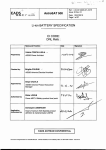
NSDGT90FRH USER MANUAL
IMPORTANT! Always read the Operators Manual and Safety Instructions
With all tools to ensure proper use and safety precautions.
USER MANUAL CONTENTS:
◎ Important Safety Rules
◎ Operating Instructions
◎ Installation
◎ Maintenance
◎ Troubleshooting
◎ Parts List
◎ Important Safety Rules
General safety warning
•
•
•
•
•
•
•
•
•
•
User must wear eye protection which conforms to ANSI specification with front and side
protection against flying object; when handling, operating, and servicing the tool. It is
employer's responsibility to enforce user and all other nearby personnel at worksite to wear
eye protection when operating the tool.
It is recommended to wear ear protection near or at the job site to prevent hearing damage.
Beware of the danger of entangled clothe and hair. Do not dress loose clothing and jewelry
at work. Keep your hair, clothing, and gloves away from moving part of the tool.
Keep your finger AWAY from the trigger when the tool is not in use. This will prevent
accidental fire of the tool.
This tool is not designed to be used in explosive atmosphere. The design of this tool will
generate spark and the exhaust will also cause possible danger to ignite highly flammable
fuel or gas. Do not use this tool in this kind of environment. Please also not smoke while
using or handling the tool and fuel cell.
The fuel cell is high pressure liquefied gas bottle. Keep it away from spark, fire or high temp
and explosive environment. Do not puncture the bottle or attempt to open the fuel cell. When
the fuel used up, do not incinerate the bottle. Follow the recycle instruction on the bottle.
Do not store the tool in temperature above 120°F (50°C). High temperature will result in
explosion or fire and the release of flammable gas. When not in use, keep the tool from high
temperature source or direct sun light.
The tool needs to be used in well ventilated area. Do not inhale the exhaust or fume or the
gas because they are potentially dangerous to human body.
Keep body balance when operating the tool, do not over reach.
Keep the tool, fuel, charger and battery out of the reach of children. The tool is dangerous in
the hand of untrained person.
Tool safety warning
•
•
•
•
•
•
•
•
•
•
Do not modify or repair the tool in any method other than the original design. The tool may
function unexpectedly after the modification and cause dangerous.
Never point the nozzle of the tool toward anyone including yourself. This tool is
self-contained with power source and will be dangerous if not use with care. Always assume
the tool is loaded with nail and fuel.
Do not drive this tool over materials that are too hard or too soft. Hard materials can cause
NailScrews to ricochet and hurt people, soft materials may penetrate easily and cause the
nail to free fly.
Please use only lubrication liquid specified in this manual to perform the lubrication. Use
other lubrication may cause damage to the tool and the risk of malfunction that will injure the
operator.
Please keep the tool in clean condition, wipe off grease or oil after work. Do not use any
solvent based cleaner to clean the tool. It is possible the solvent will deteriorate the rubber or
plastic components on the tool. Greasy handle and body will cause accidental drop of the
tool and injury to nearby person.
Please use fastener specified in this manual and on the tool. Use fastener that is not
compatible to the tool will cause jamming of the tool and injury to operator or nearby person.
Do not use the tool to perform other job than designate function. Especially not use the tool
as a hammer, impact on the tool will increase the risk of cracked body and accidental
discharge of fastener.
Remove the fuel cell and battery before performing maintenance, repair, cleaning and jam
clearing.
Load the fastener at last to prevent unexpected danger of loading fuel cell and battery.
Never use the tool if the trigger and safety or springs are damaged in any way.
Fuel safety warning
•
•
Use only the fuel cell recommended by the manufacturer. Read the Safety Data Sheet to
understand more of your fuel cell contents.
Recycle the empty fuel cell according to the local law. Do not attempt to recharge the fuel
cell or incinerate the empty fuel cell.
Battery safety warning
•
•
•
•
•
Use only batteries that are supplied by the manufacturer.
Recycle the battery according to local law. Do not incinerate the battery of attempt to
puncture and crush the battery.
Do not immerse the battery into water or other fluid. Do not expose the battery to rain or
snow.
Do not expose the battery or tools loaded with battery under direct sun light exposure.
Prevent to put above items at temperature higher than 120°F (50°C). Overheating the
battery can result in explosion or fire.
Do not allow direct contact of the battery nodes with metal or conductive material.
Charger safety warning
•
•
•
•
•
•
•
•
Do not use the charger in explosive atmosphere. The electrical device is not designed to use
in such environment.
Do not charge battery outdoors or in temperatures below 40°F (5°C).
Do not puncture or attempt to open battery case or cells.
Do not immerse the charger into water or other fluid. Do not expose the charger under rain
or snow.
Do not use the charger if the cord is damaged or the charger is defect.
Unplug the charger by pulling the adaptor unit, not by pulling the cord.
Do not cover the charger with anything.
Do not use a step up transformer or engine generator as the power source of the charger.
◎ Fuel cell activation Instructions
Cordless Fuel Cell Installation Procedure
Before inserting the fuel into a tool, see instructions below.
The fuel valve is already partially installed onto the can. To fully install the valve complete the
following steps:
1. Press downward on the front side of the valve (Stem side) until it seats.
2. Press downward on the rear side of the valve until it seats.
The valve is now completely seated onto the fuel can and can be inserted into the tool.
Cordless Fuel Cell Installation Procedure
Before inserting the fuel into a tool, see instructions below.
The fuel valve is already partially installed onto the can. To fully install the valve complete the
following steps:
Features and Benefits
Fuel cells tend to last about 1200 shots and have a shelf life of 18 months.
Load and unload the fuel cell
•
•
•
Open the fuel cell door by pulling the door and rotate.
Insert the fuel cell into the chamber. Align the fuel cell nozzle into the red V groove receiver
of the fuel cell stem on the tool.
Close the fuel cell door.
(If Incorrect REPEAT STEPS ABOVE in Fuel Cell Activation Instructions Section)
Load and unload the fastener
•
•
Connect to battery and fuel cell before you load the fasteners. Let the Nailer cycle through
once before firing first fastener.
Point the nozzle away from any personnel and keep your finger out of trigger when loading
the fastener.
•
To load the nail, slide in the nail strip into the magazine until the nail strip passed the nail
stopper.
•
Pull the pusher until it is beyond the stopper.
•
Release the pusher to engage the nail strip and feed it into the nozzle.
•
To unload the fastener from the magazine, press the release lever on the pusher and tilt the
tool to slide the nail strip to the rear of the magazine.
•
Unload the nail strip by press the nail stopper and slide out the nail strip.
Depth of drive adjustment and no mar tip installation
•
This tool is equipped with tool free depth of drive adjustment. Test the depth of drive on
scrap piece before you start your work.
•
•
Turn the knob to adjust the depth of drive.
Repeat above procedure until you find your desired depth of drive setting.
Rubber No Mar Tip Can Be Removed
Actuate method and the steps to fire the tool
•
•
•
•
This tool is equipped with single sequential trigger system only.
To actuate the tool, depress the safety against the work piece, and then pull the trigger.
To actuate the tool again, you will need to release the safety fully and release the trigger
before you repeat above procedure.
Make sure you are driving against work piece before you pull the trigger.
Jam clearing for framing tool
•
•
•
•
•
In the case of nail jam, disconnect the power source (fuel cell and battery) before you
perform any action.
Use a #2 Phillips screw driver to insert into the drive channel.
Tap the screw driver with a hammer to push back the driver blade and release the jam.
Remove the jammed nail with needle nose pliers or similar type of tool. Do not use your
hand to remove the nail.
If you failed to remove the jammed nail by above method, remove the magazine by
un-thread the connecting bolt and remove the jammed nail with needle nose pliers.
Assemble the magazine back before further use.
Charge the battery and LED on tool and charger
•
•
•
•
•
•
•
There is battery comes along with the tool. It will take 2 hours before the new battery can be
fully charged.
There will be no LED light when the charger is connected to electric and no battery is on the
charger.
The LED on the charger will turn red when it is charging a battery.
The other LED will turn green when the battery is fully charged.
In the case of battery failure, the red and green LED will blink in sequence.
When the tool is connected to a charged battery, the LED indicator on the tool will turn
green.
If the tool is running out of battery, the indicator LED will turn red. When the LED indicator
turns red, stop using the tool and replace the battery.
◎ Composite Deck Installation
TREX®,
MOISTURE
SHIELD®
&
CHOICEDEK®
Installation
with
the
model
NSDGT90FRH Cordless NailScrew Driver™
Recommendations for driving the UFO™ Composite Ballistic NailScrews® through
Composite Decking material to a wood frame or light gauge metal frame.
Best tools; UFO NailScrew® Driver NSDGT90FRH Cordless or UFO’s NSD9021
1. RE: Combo Trim Head Ballistic NailScrews® (with T-15 Torx inserts in heads) for many kinds of decks
including: Composite, PVC, all Treated Lumber, Cedar, Redwood and many kinds of Hardwoods from around
the world. If you are using denser composites this is the best top down Ballistic NailScrew® for you. In cool
or cold weather you may need 120 lbs of pressure at the tool. Most 83 series / 83 mm size tools will do the
job with this newest Combo Trim Head Ballistic NailScrew®. Our larger 90 series / 90 mm tool is available if
you need more power for your combination of building materials (Example tough composite boards to 14-16
gauge steel studs or Tiger wood and Ipe).
2. Composite Ballistic NailScrews® (with #2 Robertson Square Drive inserts in heads) are approved for Trex
Accents and Contours as well as AERT MoistureShield and ChoiceDek. These work great in PVC boards
like Azek and many others. The Ballistic NailScrew® Driver tool #NSD9021 has enough power to do tough
jobs for professional use. These NailScrews® are also great for treated lumber wood decking!
3. Tips that will help your installation with Ballistic NailScrews®
a. Sequential fire will help keep you from double firing the tool. Depth of drive adjustments work well.
b. Add rubber or plastic noise piece / guard to keep from scratching softer decking materials.
c. Dedicated air compressor with 100 to 120 lbs of consistent pressure at the tool (adjust the compressors
kick-on controls to stay within a 10 lbs range), you can reduce the pressure as needed.
d. Temperature will change your composite density greatly, and below 50 degrees a full size 90 mm tool
might be needed to do the best installation.
e. Use a 3/8” diameter hose, as short as possible; 25’ best or 50’ maximum to get consistence driving.
f. Drive NailScrews® perpendicular to the decking surface and always wear eye protection!
g. Do multiple test runs with scraps of the actual materials that you intend to use before starting the deck
(hot and cold weather will affect this greatly).
4. Tips that will help your removal of Ballistic NailScrews®
a. Best to use a low RPM Cordless Impact Driver or Drill; very strong and slower is better.
b. Start slow to avoid stripping the wood fibers and then speed up after about 3 revolutions (once the
NailScrew® begins to reverse out of the hole).
c. NailScrew® can be backed out part way and then re-driven with an Impact Driver or a hammer.
d. More tips can be found on our web site and on the videos at www.HowToNailScrew.com
5. The finished decking look (with NailScrew®, driven through the Composite Decking materials) should be
reviewed with customers / home owners beforehand. The NailScrews® smaller heads will give your customer
a very clean looking deck. “The better the installer / mechanic, the better the project!”
RSDescription: CORDLESS Ballistic NailScrew Driver: Model NO. NSDGT90FRH color matched
Ballistic NailScrews® thru the LifeCycle™ composites into the deluxe 16ga black powder coated steel
frame and stop the drive when it is flush. This is possible, but must be done a little differently that what you
may be used to when you are attaching wood to wood, so please follow these step by step rules when
installing LifeCycle™ Fencing. For more information on installation of LifeCycle™ Fencing please visit
(www.lifecyclefencing.com)
Consistent power is the key to success. The cordless gas tool allows the same energy each and every
time .
The high velocity this creates is our friend. Please understand this is where we are different than
fastening to wood. Always be sure to test fire into the actual material scraps, adjusting the depth of
drive on the tool (See Depth of drive adjustment section above) to compensate for the excess
drive.
The NSDGT90FRH is designed to be sequentially fired only! First, place the nose of the tool where
you want the fastener to be; this will depress the safety. Second, use the trigger to fire the tool in this
sequence each and every time. The tool must be placed squarely and very firmly; try not to let the tool
bounce off the work surface. This will give a more consistent drive and finished look.
When you have a Ballistic NailScrew® that is too high or low, use a T15 Torx bit in a screw driver or
impact driver to adjust the NailScrew. Go very slowly to the desired depth. High rpm will strip out the
NailScrew. Go slow and you will be amazed at the results.
This is very important! Please make sure the steel frames are set very firm--not springy or bouncy. If
the frame moves much, it will cause the NailScrews to be set very inconsistently.
The NSDGT90FRH has very low noise level, making it ideal for installing Ballistic NailScrews® for
Composite fencing to wood or steel, construction of pallets and crate assembly, composite or wood deck
construction, roof decks, sub-floor, sidewall sheathing, anywhere screws are being used and you want to
save time installing and still do a quality job etc. (see www.911-nails.com)
◎ Maintenance
Warning: disconnect the power source (fuel cell and battery) before performing any maintenance
General maintenance
Keep the tool in clean condition at all times. Wipe off grease or oil with dry clean cloth to prevent
accidental tool drop. Avoid using solvent base cleaner to clean the tool, certain solvent will damage
or weaken the composite parts of the tool. Clean the intake filter regularly to keep the tool in full
efficiency.
Lubrication and cleaning
• This tool should not need extra lubrication since the fuel already contains some lubrication oil.
• The combustion chamber and cylinder can be cleaned by applying automobile carburetor cleaner.
You will need to remove the 2 screw on the handle and 4 screws on the top cap to expose the
internal component of cylinder.
Cold weather
This tool is not suggested to be used in cold winter. The cold weather will decrease the combustion
efficiency and also the battery performance. Use the tool only at temperature above: -7°C(19°F).
◎ Troubleshooting
Following are common operating problems and solutions. Please read carefully for suggested
solutions. If any of the following symptoms occur during tool operation, stop using the tool
immediately or serious personal injury could result! Only a qualified person or an authorized service
center can perform repairs or replacement of tool parts.
ONLY USE PARTS AND ACCESSORIES RECOMMENDED BY THE MANUFACTURER.
Parts & Service Contact: http://elder-hayesinc.com or call 1-800-769-0775
◎ Parts List
DESCRIPTION
ITEM
101
102
103
104
105
PART
NO.
840866
840869
920164
830582
840864
DEFLECTOR
FILTER
HEX.SOC.HD.BOLT
FLAT WASHER
COLLAR
202
203
301
302
303
PART
NO.
840841
840853
840872
840871
840876
106
840860
CAP
304
840846
107
108
109
110
111
112
113
114
115
840840
840839
840882
840905
840897
840844
840877
840870
840889
305
306
307
308
309
310
311
312
313
920660
840856
840879
820655
820645
840902
920348
840868
840848
116
840883
314
840874
SPACER
117
118
119
120
121
122
123
840909
840865
840845
840907
840898
840838
920151
315
316
317
318
319
320
321
840890
840878
840849
840867
920199
840900
840893
124
840892
322
840847
125
126
127
128
129
130
131
132
133
134
840851
840884
840880
920323
840910
840904
840859
840913
840850
840843
323
324
325
326
327
401
402
403
404
405
840862
840891
820706
840894
840901
840933
820811
820660
920664
840946
FUEL ACTUATOR
BUSH-FUEL ACTUATOR
PIN-FUEL ACTUATOR
HANDLE B
HEX.SOC.HD.BOLT
SELF TAPPING BOLT
MOTOR FAN SWITCH LEVER
BRACKET-MOTOR FAN
SWITCH LEVER
BATTERY NODE BRACKET
BATTERY NODE
TAP BOLT
LED COVER
SELF TAPPING BOLT
MAGAZINE A
FLAT WASHER
HEX.SOC.HD.BOLT
HALF ROUND HD.HEX.BOLT
STEEL CHANNEL
135
840858
406
920328
HALF ROUND HD.HEX.BOLT
136
137
138
139
140
840930
840885
840887
840886
840881
PCB ASSEMBLY
SPARKLER
MOTOR
C - RING
HALF ROUND HD.HEX.BOLT
FAN MOTOR BRACKET
SLEEVE MOTOR
WASHER-MOTOR SHAFT
FUEL STEM ADAPTER
END CAP-COMBUSTION
CHAMBER
O - RING
SEAL
SEAL PLATE-MOTOR
IN-CONCENTRIC RING
HEX.SOC.HD.SCREW
COOLING FAN ASSEMBLY
HEX.SOC.HD.BOLT
UPPER COMBUSTION
CHAMBER
PACKING
COMBUSTION CHAMBER
WASHER
HEX.SOC.HD.BOLT
O-RING
C - RING
PISTON RING
DRIVER UNIT
BUMPER
CYLINDER
BUMPER-COMBUSTION
CHAMBER
NOSE PIECE
EXHAUST MESH PLATE
EXHAUST BAFFLE
REED VALVE
CLEANER
TRIGGER
SAFETY
GUN BODY
WASHER CAP
CAP NUT
CONNECTOR
PLATE-NOSE/CYLINDER
HEX.SOC.HD.BOLT
SPRING COVER
WASHER-NOSE COVER
HEX.SOC.HD.BOLT
HEX.SOC.HD.BOLT
FLAT WASHER
LOCK NUT
HANDLE A
HANDLE BOLT
407
408
409
410
411
830770
830771
820685
810854
920186
PROTECTING HOOD COVER
STOP NAIL PLATE
HALF ROUND HD.HEX.BOLT
SPRING
ROLLING ELEMENT
ITEM
DESCRIPTION
141
142
143
144
145
146
147
148
149
150
151
152
153
154
155
201
840888
920945
840896
840852
840854
840911
840921
840857
840908
840875
840919
840906
810834
810436
840895
840842
DEFLECTOR
HEX.SOC.HD.BOLT
HEX.SOC.HD.BOLT
SAFETY C
SAFETY SPRING
O - RING
SAFETY B
FEED BUMPER
SPRING PIN
ADJUST AXIS
SAFETY A
E - RING
PROTECTIVE CASING
FIXED RING
SOURCE
SPRING
412
413
414
415
416
417
418
419
420
421
422
423
424
425
426
427
428
820432
830766
920627
920687
810414
830767
920379
840926
830015
840917
840899
840861
840873
830591
840903
840863
840855
ROLL PIN
PROTECTING HOOD COVER
URETHANE RETAINER
HEX.SOC.HD.BOLT
TRIGGER PIVOT PIN
PUSHER
SPRING
SQUARE UNITS
BOLT CAP
POSITIONING SHEET
HEX.SOC.HD.SCREW
POSITIONING AXIS
SPRING RETAINER
HEX.SOC.HD.BOLT
FLAT WASHER
RAFTER HOOK BRACKET
RAFTER HOOK
ONLY USE PARTS AND ACCESSORIES RECOMMENDED BY THE MANUFACTURER.
Sales & Service Contact: http://elder-hayesinc.com or call 1-800-769-0775
NSDGT90FRH
For Part and Service Contact: http://elder-hayesinc.com or call 1-800-769-0775