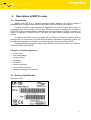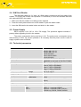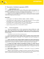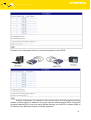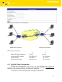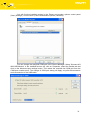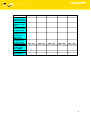
1
Content
1.
2.
Safety instructions
Description of the ER75i router
2.1. Introduction
2.2. Delivery Identification
2.3. Antenna Connection
2.4. SIM Card Reader
2.5. Power Supply
2.6. Technical parameters
2.7. Description of individual components of ER75i
2.7.1.
GSM/GPRS/EDGE module
2.7.2.
Control microcomputer
2.8. User interfaces (Connectors)
2.8.1.
Connection of the PWR Supply Connector
2.8.2.
Connection of the ETH Connector
2.8.3.
Connection of the Connector USB
2.8.4.
Connection of the Connector PORT1
2.9. Modem status indication
2.10. Putting into operation
3. Configuration setting
3.1. Network Status
3.2. DHCP Status
3.3. GPRS Status
3.4. System Log
3.5. Network Configuration
3.6. GPRS Configuration
3.7. NAT Configuration
3.8. GRE Tunnel Configuration
3.9. SMS Configuration
3.10. SIM PIN configuration
3.11. Change password
3.12. Update firmware
3.13. Reboot
3.14. Default settings
3.14.1. LAN Configuration
3.14.2. GPRS Configuration
3.14.3. NAT Configuration
3.14.4. GRE Tunnel Configuration
3.14.5. SMS Configuration
4. Driver installation
5. Control by AT commands
6. Possible problems
7. Customer´s care
8. Guarantee Claim Guidelines
9. Guarantee certificate
3
4
4
4
5
6
6
6
7
7
7
8
9
9
9
9
10
10
12
12
13
14
14
15
16
17
20
21
23
23
23
24
24
24
25
25
26
26
28
30
30
30
31
34
2
1. Safety instructions
Please, see the following instructions:
•
The communication module ER75i must be used in compliance with any and all applicable
international and national laws and in compliance with any special restrictions regulating
the utilization of the communication module in prescribed applications and environments.
•
To prevent possible injury to health and damage to appliances and to ensure that all the
relevant provisions have been complied with, use only the original accessories.
Unauthorised modifications or utilization of accessories that have not been approved may
result in damage to the communication module and in a breach of applicable regulations.
Unauthorized modifications or utilization of accessories that have not been approved may
result in the termination of the validity of the guarantee.
•
The communication module ER75i must not be opened. Only the replacement of the SIM
card is permitted. Caution! The SIM card might be swallowed by small children.
•
Voltage at the feed connector of the communication module must not be exceeded.
•
Do not expose the communication module to extreme ambient conditions. Protect the
communication module against dust, moisture and high temperature.
•
It is recommended that the communication module should not be used at petrol stations.
We remind the users of the duty to observe the restrictions concerning the utilization of
radio devices at petrol stations, in chemical plants, or in the course of blasting works in
which explosives are used.
•
Switch off the communication module when travelling by plane. Utilization of the
communication module in a plane may endanger the operation of the plane or interfere with
the mobile telephone network, and may be unlawful. Failure to observe these instructions
may result in the suspension or cancellation of telephone services for the respective client,
or, it may result in legal sanctions; it may also result in both eventualities.
•
When using the communication module in close proximity of personal medical devices,
such as cardiac pacemakers or hearing aids, you must proceed with heightened caution.
•
If it is in the proximity of TV sets, radio receivers and personal computers, the telephone
may cause interference.
•
It is recommended that you should create an appropriate copy or backup of all the important
settings that are stored in the memory of the device.
3
2. Description of ER75i router
2.1. Introduction
EDGE router ER75i is a compact electronic device based on the MC75 module of
SIEMENS which enables data transfers using GSM, GPRS and EDGE technologies.
Primarily, the ER75i router expands the capabilities of the MC75 module by the option of
connecting more PCs by means of the built-in Ethernet interface. In addition, the firmware of
the ER75i router provides automatic establishment and maintenance of GPRS connection. By
means of integration of DHCP server it provides the users simple installation and Internet
access.
In addition, the ER75i router is equipped with the USB 2.0 Full Speed interface which is
designed only for connection to PC with Windows 2000 or Windows XP operating system. For
its putting into operation it is sufficient to install drivers from the supplied CD to the PC.
Na přání zákazníka je možné vybavit router ER75i modulem portu PORT1 a rozšířit tím
funkčnost EDGE routeru ER75i.
Examples of Possible Application
• mobile office
• fleet management
• security system
• telematics
• telemetrics
• remote monitoring
• remote track monitoring
• vending and dispecher machines
2.2. Delivery Identification
Specimen Label:
4
Basic delivered set of ER75i includes:
•
EDGE router ER75i
•
power supply
•
crossover UTP cable
•
external magnetic antenna
•
installation CD containing instructions and drives
In addition to the basic it is possible to deliver:
•
modul of port PORT1 (RS232, RS485, RS422 a MBUS)
•
USB A-B cable
•
External magmetic antenna
•
plastic clips for the DIN bar with fixing screws
Router ER75i is standardly designed for
•
mounting to a panel using through holes.
•
or possibly to be put on a worktop
•
for mounting onto the DIN bar the plastic clips are added
2.3. Antenna Connection
The whip antenna is connected to ER75i using an FME on the back panel.
External whip antenna:
5
2.4. SIM Card Reader
The SIM card reader for 3 V and 1.8 V SIM cards is located on the front panel of the
modem. For putting the modem into operation it is necessary to insert an activated SIM card
with unblocked PIN in the reader.
1. Make sure that the modem is not being power-supplied.
2. Press the small yellow button next to the reader to eject the reader holder.
3. Insert the SIM card in the reader holder and slide it in the reader.
2.5. Power Supply
ER75i requires +10 V DC to +30 V DC supply. The protection against reversal of
polarity without signaling is built in the modem.
The power consumption during receiving is 1W. The peak power consumption during
data sending is 3.5W. For correct operation it is necessary that the power source is able to
supply a peak current of 500mA.
2.6. Technical parameters
GSM modul
Complies with standards
Frequency bands
Transmit power
Temperature range
Supply voltage
Consuption
operation
storage
reception
transmission
Dimensions
Weight
Antenna connector
User interface
ETH
USB
PORT1
SIEMENS MC75
EN 301 511
EN 301 489-1 V1.6.1
EN 301 489-7 V1.3.1
EN 55 022:2001
EN 61 000-3-2:2001
EN 60 950:2001
EGSM850, EGSM900, GSM1800 a
GSM1900 on the basis of VO-R/1/07.200514
Class 4 (2W) for EGSM850
Class 4 (2W) for EGSM900
Class 1 (1W) for GSM1800
Class 1 (1W) for GSM1900
-20 oC až +55 oC
-40 oC až +85 oC
10 až 30 V DC
1W
3,5 W
30x90x102 mm (attachment to DIN bar
35mm)
140 g
FME – 50 Ohm
Ethernet – connector RJ45 (10/100 Mbit/s)
USB 2.0 – connector USB-B
Optional – connector RJ45 (150 b/s –
115200 b/s), RS232, RS485, M-BUS
6
2.7. Description of individual components of ER75i
2.7.1.
GSM/GPRS/EDGE module
SIEMENS MC75 OEM module is used for GSM network wireless communication. It is
integrated in the printed circuit board. The slide-out SIM card reader is accessible from the
front panel. The FME antenna connector is accessible from the back panel.
The MC75 module is equipped with the USB 2.0 Full Speed interface which is brought
to the USB-B connector marked USB. The MC75 module is connected to the control computer
via the RS-232 high-speed serial interface.
Modul MC75
•
communicates in four GSM bands (850MHz, 900MHz, 1800MHz, 1900MHz).
•
in the GPRS mode it is able to transmit in four "Time Slots" and receive in four too (GPRS
multi-slot class 12 – the maximum bit rate of reception is 85.6 kb/sec).
•
in the EDGE mode it is able to transmit in two "Time Slots" and receive in four (EGPRS
multi-slot class 10 – the maximum bit rate of reception is 236.8 kb/sec).
•
supports coding schemes CS1 to CS4 and MCS1 to MCS9.
2.7.2.
Control microcomputer
The core of the ER75i router is a 32-bit microprocessor Motorola M5208 with 16 MB
RAM, 4 MB FLASH EEPROM, serial interface RS-232 and an Ethernet interface 10/100
Mbit/s. The microcomputer is connected to the MC75 OEM module through the serial interface
and controls the communication via GSM/GPRS. Towards the user it is connected on the
Ethernet interface.
The software is built on the uClinux operating system.
For the connected devices the modem provides the DHCP service (Dynamic Host
Configuration Protocol) which enables individual clients (computers) to achieve the TCP/IP
configuration when being put into operation. The IP address is set with the assistance of
ER75i.
Thanks to the NAT function (Network Address Translation) the modem enables sharing
of the Internet connection by many computers. NAT translates the internal network addresses
and enables each user in the network a transparent access to the external web via a single IP
address. NAT is mechanism which allow reduction of needed quantity unique IP address.
In addition the modem supports the possibility of creation of a GRE tunnel for
connection of two remote LANs to one LAN, which is apparently homogenous. GRE – General
Routing Encapsulation protocol is used without encryption. While using GRE tunnel must exist
on the second side of tunnel equipment buttressing GRE tunnel, for example PC with OS
Linux, CISCO router or ER75i.
ER75i dispose function Port Forwarding, it´s improvement of tunnel for forwarding
datas on port another´s equipment.
Security of data transmission is design by the help of services IPSEC (IP Security).
Service IPSEC provides autenticity check of both knots and security of the encryption carried
data. For protections trustworthiness of data it is using symmetrical encryption.
7
Integrated Dynamic DNS client allows automatic updating of third order domain, which
it is provides by server www.dyndns.org so, that this domain will always route on IP address
subsidiary GSM operator.
The modem settings are saved in the FLASH EEPROM memory. All configuring of the
modem can be done through a web interface (HTTP) which is security passwords.
2.8. User interfaces (Connectors)
On the back panel of ER75i the following connectors are located:
•
one RJ12 connector (PWR) – for connection of the power supply adapter
•
one RJ45 connector (ETH) – for connection into the local computer network
•
one RJ45 connector (optional PORT1) – for connection of the local any arragement over
RS232, RS485 or MBUS
•
one FME connector (ANT) – for connection of the antenna
•
one USB-B connector (USB) – for connection of the router to the PC.
Back panel
Front panel
8
2.8.1.
Connection of the PWR Supply Connector
Panel socket RJ12.
Pin
number
1
2
3
4
5
6
2.8.2.
Signal
mark
+UN
NC
NC
+UN
GND
GND
Description
Positive pole of DC supply voltage (10 to 30 V)
Signal not connected
Signal not connected
Positive pole of DC supply voltage (10 to 30 V)
Negative pole of DC supply voltage
Negative pole of DC supply voltage
Connection of the ETH Connector
Panel socket RJ45.
Pin
number
1
2
3
4
5
6
7
8
2.8.3.
Signal
mark
TXD+
TXDRXD+
EPWR+
EPWR+
RXDEPWREPWR-
Description
Transmit Data – positive pole
Transmit Data – negative pole
Receive Data – positive pole
DC supply voltage from the switch – positive pole
DC supply voltage from the switch – positive pole
Receive Data – negative pole
DC supply voltage from the switch – negative pole
DC supply voltage from the switch – negative pole
Connection of the Connector USB
Panel socket USB-B.
Pin
Signal
number
mark
1
VCC
2
USB data 3
USB data +
4
GND
2.8.4.
Popis
Positive pole of 5V DC supply voltage
USB data signal – negative pole
USB data signal – positive pole
Negative pole of DC supply voltage
Connection of the Connector PORT1
Panel socket RJ45.
Wiring of connector RJ45 is depended on using port PORT1.
9
2.9. Modem status indication
On the front and back panel of the modem there are altogether four LED indicators,
which inform on the modem status.
Panel
Colour
Description
Meaning
Blinking 1:9 ................... join GPRS connection
Blinking 9:1 ................... esteblishing of GPRS connection
Permanently on ……….. starting of the ER75i
Front
Green
PWR
Front
Red
GSM
Back
Green
–
On ...................... selected 100 Mbit/s
Off ..................... selected 10 Mbit/s
Back
Green
–
On........................ the network cable is connected
Blinking ……….. data transmission
Off ...................... the network cable is not connected
Blinking ………..GSM/GPRS communication in progress
2.10. Putting into operation
Before putting the ER75i router into operation it is necessary to connect all components
needed for the operation of your applications, and the SIM card must be inserted (the modem
is off).
The modem is put into operation by connection of the power supply to the modem. In
the default setting the modem starts to login automatically to the preset APN. The behaviour
of the modem can be modified by means of the web interface which is described in the
following chapter.
10
11
3. Configuration setting
Monitoring of status, configuration and administration of the ER75i router can be
performed by means of the web interface which is available after entering the IP address of
the modem in the web browser. The default IP address of the modem is 192.168.1.1.
Configuration may be performed only by the user "root" with initial password "root".
The left part of the web interface contains the menu with pages for monitoring of the
Status, Configuration and Administration of the ER75i router.
After green LED diode start blinking it is possible restore initial setting of the router by
pressing buttons RST, whereby it is fulfilment restoration configuration and reset (green LED
will be on).
3.1. Network Status
To view the system information about the modem operation, select the
System Informations menu item. The bottom part of the window contains information about the
system memory usage. The upper part of the window displays detailed information about
active interfaces:
•
eth0 – parameters of networks interface
•
ppp0 – PPP interface (active connection to GPRS/EDGE)
•
gre1 – interface of the GRE tunnel
•
ipsec0 – interface of the IPsec tunnel
By the each of interface are then painted next information
•
•
•
•
•
•
•
•
•
•
•
•
HWaddr – hardware (unique) address of networks interface
inet – own IP address
P-t-P – IP address second ends connection
Bcast – broadcast address
Mask – mask of network
MTU – maximal size of packet, which is equipment able transmit
Metric – number of routers, over which packet must pass
RX packets – received packets, errors – number of errors, dropped – dropped
packets
TX packets – transmit packets, errors – number of errors, dropped – dropped packets
collisions – number of collisions
RX bytes – total number of received bytes
TX bytes – total number of transmit bytes
From network information it is possible reproach GPRS connection state. When the
GPRS connection is active, it is in system information painted ppp0 connection.
12
3.2. DHCP Status
Information about IP addresses which was allotted of DHCP server to ER75i, it is
possible find in menu in sum DHCP:
•
•
•
•
•
lease 192.168.1.2 (generally IP address) – assigned IP address
starts – information about time of assigned IP address
ends – information about time of termination IP address
hardware ethernet – hardware MAC (unique) address
uid – unique ID
In the extreme the DHCP status can display to one’s IP address two DHCP status,
causes of that it can be reset of network cards.
13
3.3. IPsec status
Information on actual IPsec tunnel state it can be call up option entries NTP in menu.
Detailed information description here painted it can be find on the following link
http://www.freeswan.org/doc.html.
3.4. GPRS Status
The item GPRS in menu contains information about PLMN (code of operator), cell,
channel and signal (information are by a single application find out on power up MC75). In
bottom of window hereof windows it is GPRS Connection Log, where there are information
about make up GPRS connection and pertinent problems on this formation.
3.5. DynDNS status
DynDNS up - dating entry result on server www.dyndns.org it can be call - up option
DynDNS item in menu.
14
3.6. System Log
In case of any problems with connection to GPRS it is possible to view the system log
by pressing the System Log menu item. The upper part of the window displays possible errors
at GPRS connection establishment. After switching on the log daemon by pressing the Start
button, the bottom part of the window displays detailed reports from individual applications
running in the modem. To update the contents of the window press the Refresh button.
3.7. Network Configuration
To enter the network configuration, select the Network menu item. In the first part of
window it is possible to define the network interface IP address (IP address) and the network
mask (Subnet Mask).
In the second part of window, it is possible to define DHCP server by checking the
Enable DHCP server option. In the window it is possible to define the beginning (IP Pool Start)
and end (IP Pool End) of the pool of IP addresses which will be assigned to DHCP clients.
The changes in settings will apply after pressing the Apply button.
The DHCP server assigns to the connected clients IP addresses from the defined
address pool, IP address of the gate and IP address of the primary DNS server. It is important
to don´t overlap ranges of static engaged IP address with address allotted by the help of
DHCP, else is able to get to collision of addresses and thereby to false function of network.
15
3.8. GPRS Configuration
To enter the GPRS connection configuration select the GPRS menu item. If the Create
GPRS connection option is checked, the modem automatically tries to establish GPRS
connection after switched on. In the window it is possible to define APN, Username, Password
and IP address.
If the APN field is not filled in, the APN will be automatically assigned by the IMSI code
of the SIM card. If the PLMN is not in book of APN, then will be use default APN “internet“.
APN is added of the mobile operator.
If the IP address field is not filled in, the IP address will be automatically assigned by
the operator when establishing the connection.
If you want to establish GSM/GPRS connection via the USB interface, first you have to
uncheck the Create GPRS connection option in the modem configuration.
The choice Get DNS address from operator is given for easier configuration on client
side, by this choice it is possible to use web browser. If this field is not filled, the clients station
has not access on internet and it is possible to send data on known IP address.
If the Check GPRS connection option is checked, is active control of connection over
GPRS. The modem will automatically send the ping question on said IP address (Ping IP
Address) in periodic time intervals (Ping Interval). It is possible to use as ping IP address for
example DNS server of mobile operator.
The changes in settings will apply after pressing the Apply button.
16
Annotation:
•
•
MRU (Maximum Transmission Unit) – it is identifier of maximal size of packet,
which it is possible transfer in given environment.
MTU (Maximum Receiving Unit) – it is identifier of maximal size of packet, which
it is possible received in given environment.
By other set it may get to incorrect transmission of data.
3.9. NAT Configuration
To enter the Network Address Translation configuration, select the NAT menu item. By
checking off the Send all incoming packets to default server item and setting the
Default Server item it is possible to put the ER75i router into the mode in which all incoming
data from GPRS will be routed to the computer with the defined IP address.
If the Enable remote HTTP access field is filled in, it is maybe configuration of router
over web interface.
Choice Enable remote Telnet access makes it possible access over Telnet.
The changes in settings will apply after pressing the Apply button.
17
Example of the configuration with one connection equipment on the ER75i:
At these configuration it is important to have mark election Send all remaining incoming
packets it default server, IP address in this case is device address behind ER75i. Connected
equipment behind ER75i must have setting Default Gateway on the ER75i. At distant PING on
IP address of the SIM card matches connected equipment.
18
Example of the configuration with more connected equipment:
At these configuration the address define Server IP Address equipments wiring behind
ER75i. At distant PING matches ER75i. Access on web interface of equipment behind ER75i it
is possible by the help of Port Forwarding, when behind IP address of SIM is indicating public
port of equipment on which we want come up. At demand on port 80 it is surveyed singles
outer ports (Public port), there this port isn't defined, therefore at check election Enable repote
http access it is automatically opens web interface ER75i. If this choice isn't check and is
check volition Send all remaining incoming packets to default server fulfil oneself connection
on induction IP address. At it is not check election web interface and Default server IP address
it is request failure.
19
3.10. IPsec Tunnel Configuration
IPsec tunnel configuration it can be call - up option Ipsec item in menu. In window it
can be define off - side tunnel IP address (Remote External IP Address), address nets
behind off - side tunnel (Remote Subnet), mask nets behind off - side tunnel (Remote Subnet
Mask), address LAN (Remote Subnet), mask LAN (Remote Subnet Mask), sharable key for
both parties tunnel (Pre shared Key), service life keys (Key Lifetime) and service life IKA SA
(IKE Lifetime).
IPsec tunnel allows protected connection of two networks LAN to the to one which it
is cheek as one homogenous.
The changes in settings will apply after pressing the Apply button.
IPsec tunnel configuration:
Remote External IP Address:
Remote Subnet:
Remote Subnet Mask:
Local Subnet:
Local Subnet Mask:
Pre-shared Key:
A
10.0.0.2
192.168.2.0
255.255.255.0
192.168.1.0
255.255.255.0
test
B
10.0.0.1
192.168.1.0
255.255.255.0
192.168.2.0
255.255.255.0
test
3.11. GRE Tunnel Configuration
To enter the GRE tunnel configuration, select the GRE menu item. In the window it is
possible to define the IP address of the remote side of the tunnel (Remote External IP
Address), internal IP address of the local side of the tunnel (Local Internal IP Address), internal
IP address of the remote side of the tunnel (Remote Internal IP Address), address of the
network behind the remote side of the tunnel (Remote Subnet) and the mask of the network
behind the remote side of the tunnel (Remote Subnet Mask). The GRE tunnel is used for
connection of two networks to one which it is cheek as one homogenous.
The changes in settings will apply after pressing the Apply button.
20
Example of the GRE Tunnel configuration:
192.168.1.2
192.168.2.2
B
ppp1 10.0.0.2
A
ppp0 10.0.0.1
192.168.1.3
GRE tunel
192.168.2.1
192.168.2.3
192.168.1.1
192.168.1.4
192.168.2.4
Default Gateway 192.168.1.1
Default Gateway 192.168.2.1
GRE tunnel Configuration:
A
B
Remote External IP Address:
10.0.0.2
10.0.0.1
Local Internal IP Address:
192.168.1.254
192.168.2.254
Remote Subnet:
192.168.2.0
192.168.1.0
Remote Subnet Mask:
255.255.255.0
255.255.255.0
3.12. DynDNS Client Configuration
DynDNS client Configuration it can be call - up option DynDNS item in menu. In
window it can be define domain of third order registered on server www.dyndns.org
(Hostname), user name (Username) and password (Password).
The changes in settings will apply after pressing the Apply button.
21
3.13. NTP Client Configuration
NTP client Configuration it can be call - up option NTP item in menu. In window it can
be define address prime (Primary NTP server Address) and secondary NTP server
(Secondary NTP server Address), by the help of which router after first interface to the GPRS
from make power supply will adjust inner o'clock.
The changes in settings will apply after pressing the Apply button.
3.14. SMS Configuration
To enter the SMS Configuration it is possible extend automatic sending SMS
messages behind power up, behind GPRS connect and at losses GPRS connection. Info is
possible send on two telephone number. Unit ID is name of the ER75i which it will send in
SMS message. Unit ID may to have arbitrary form.
Behind power up ER 75i, at introduction telephone number it come SMS in the form of:
ER75i (Unit ID) has been powered up. PLMN:xxxxx,Cell:xxxx,Channel:xx,Level:-xxdBm.
where is PLMN – number of mobile operator, Cell – number of cell, Channel – used
channel, Level – level signal
Begind GPRS connect at introduction telephone number it come SMS in the form:
ER75i (Unit ID) has established GPRS connection. IP address xxx.xxx.xxx.xxx
Behind GPRS disconnect at introduction telephone number it come SMS in the form:
ER75i (Unit ID) has lost GPRS connection. IP address xxx.xxx.xxx.xxx
22
3.15. SIM PIN configuration
Change of PIN or PIN forbid it is possible in the PIN item. If it is necessary to protect
SIM card in the router ER75i by PIN number, to area SIM PIN it is written PIN number and it
is confirmed by button Store PIN. The router ER75i then by help written PIN unlocked access
to SIM card after stand by ER75i. The PIN number is possible forbid by button Unlock SIM
card.
3.16. Change password
To open the dialog box for changing the access password select the Change
Password menu item. The new password will be saved after pressing the Apply button.
In basic setting of router ER75i password is set on default form root. For higher
secure of our network we recommended to change this password.
3.17. Setting inner o’clock
One - shot setting inner o'clock of the router it can be call - up option Set Real Time
Clock item in menu. O'clock are setting according to engaged NTP server after push-button
operation Apply.
3.18. Update firmware
To view the information about the firmware version and instructions for its update select
the Update Firmware menu item. The new firmware will be checked after pressing Procházet
button and update the following pressing the Update button.
23
After successful firmware updating it is list data following statement:
where it is information about updating of FLASH memory.
After updating firmware it will IP address set on 192.168.1.1 and all values are in
defaults state. Total update time lasts for 3 - 4 minutes. During updating of firmware it has to
be reservation permanent power supply. We don’t strongly recommended distant update
because of blackout GPRS connection.
3.19. Reboot
To reboot the ER75i router select the Reboot menu item and then press the Reboot
button.
3.20. Default settings
3.20.1.
LAN Configuration
24
3.20.2.
GPRS Configuration
3.20.3.
NAT Configuration
25
3.20.4.
IPsec Tunnel Configuration
3.20.5.
GRE Tunnel Configuration
3.20.6.
DynDNS configuration
3.20.7.
NTP Configuration
26
3.20.8.
SMS Configuration
27
4.
Driver installation
Connect the USB cable to the ER75i router and to the PC. Windows detects ER75i as
a new USB modem, starts the Add Hardware wizard and requests the driver for "MC75" or
„Siemens AG WM USB Modem“. Follow the instructions of the wizard and enter the path to the
"usbmodem.inf" file. Windows will copy the needed files to your computer and configure the
modem by assigning a free COM port. After completion of copying the files click on the Finish
button.
28
You will find the installed modem in the Phone and modem options control panel
(Start | Settings | Control Panel | Phone and Modem Options | Modems).
.
You can change the assigned COM port in the Device Manager. Select “Siemens AG
WM USB Modem” in the installed devices list, click on Properties, select the Details tab and
click on the Advanced port settings button. Then select the required free COM port from the
COM port number menu. The change of COM port setting will apply only after disconnection
and reconnection of the USB cable.
29
5. Control by AT commands
Modem ER75i is controled and programed by AT commands. Structure of the AT
command match used modul MC75. AT commands is possible on website
www.siemens.com/wm
6. Possible problems
At some network cards is able to set in situation, when it is not possible connect
ER75i. This problem it is possible solve the following steps:
•
•
•
hand by selection communication rates 10 MB/s in property network cards
connect ER75i over switch
start computer till after finalization start ER75i
7. Customer´s care
Up to date information about product are on website:
http://www.conel.cz/
Upkeep-advices:
With SIM-card may be handled carefully as with credit card. Do not train, do not scratch on this
and do not parade to static electricity.
During clean of the modem do not use agresive chemicals, solvents and abrasive cleaner!
Siemens company following declared, that the modem narrated in this user´s guide fit all basic
demands of directive 1999/5/EC (R&TTE).
Declaration about consistency was issue and is possible get it at producer.
30
8. Guarantee Claim Guidelines
Dear customer,
The product that you have purchased was tested by the manufacturer and, before it
was sold, the product’s functions were checked once more by our company’s technician.
However if, in spite of the above-mentioned measures, a breakdown of this product occurs
during the guarantee period, which makes proper utilization of the product impossible, we
ask you to observe the Guarantee Claim Guidelines when asserting a guarantee claim.
To facilitate the possible guarantee claim procedure, please, when taking over the
product, make sure that the seller, who is selling you the product, has properly filled in the
relevant parts of the guarantee certificate, including the date of sale, stamp and signature.
The rights and obligations arising out of the guarantee of products are regulated in
particular by the provisions of Sections 616 to 627 of the Civil Code and by the provisions of
Sections 15 to 19 of Act No. 634/1992 Coll., the Act on Consumer Protection. The provided
guarantee does not affect the rights of the buyer which are related to the purchase of the
thing according to specific legal regulations.
This guarantee claim procedure applies to the products that have been purchased.
This guarantee claim procedure does not apply to the services that have been provided.
Guarantee periods of products
A guarantee of the purchased device, power supply unit, antenna, data cable, and
possible accessories is provided, with a guarantee period of 24 months from the date of sale.
The date of sale is at the same time the date of acceptance of the product by the customer.
Lodging a guarantee claim
The guarantee claim must be lodged at the seller from whom the relevant object of
the guarantee claim has been purchased. When lodging the guarantee claim, the
customer is to submit the properly filled-in guarantee certificate and the complete
object of the guarantee claim. The object of the guarantee claim should be submitted
in a state corresponding to the state at the sale.
Caution!!!!!
The seller does not guarantee that individual settings or data stored in the object of
the guarantee claim will be retained.
When lodging the guarantee claim, the customer is obligated to specify the particular
defect of the guarantee claim object, possibly its symptoms and, furthermore, the particular
right resulting from the liability for defects that he is asserting.
Settling a guarantee claim
Depending on the circumstances, the seller shall ensure the defect removal free of
charge, possibly, the seller shall exchange the object of the guarantee claim for a new
product or, possibly, settle the guarantee claim in a different way which is in compliance with
the Civil Code and with the Consumer Protection Act.
At the moment when the customer has lodged the guarantee claim and the object of the
guarantee claim has been accepted by the seller, running of the guarantee period is
interrupted. Running of the guarantee period shall continue from the date of acceptance of the
repaired object of the guarantee claim or of the exchanged faultless product by the customer
or, in the event that neither of the two has been accepted by the customer, from the date when
the customer was obligated to accept the repaired object of the guarantee claim or the
exchanged product. In the event that a guarantee claim resulting from a defect covered by the
guarantee has been lodged and the defective object of the guarantee claim has been
31
exchanged by the seller for a new product (including the exchange of the IMEI), the ownership
of the original object of the guarantee claim is passed hereupon onto the seller, and the
ownership of the new product, onto the buyer. A new guarantee period starts running from the
date of acceptance of the new product. In the event that the seller, upon agreement with the
customer, has settled the guarantee claim by exchanging the object of the guarantee claim for
a faultless product, the new guarantee of the product shall expire as follows:
1. after the expiration of a period of 12 months from the date of acceptance of the
exchanged product by the customer;
2. on the date when the guarantee period of the original product (the object of the
guarantee claim) would have expired if the original product had not been
exchanged, whichever is later.
3. The guarantee claim is not justified if the defect being claimed has not been
detected by the seller within the framework of the guarantee claim settlement, or
if the guarantee does not apply to the defect of the product pursuant to Article 4
of the Guarantee Claim Guidelines.
4. If the defect being claimed has not been detected, and the functional state of the
guarantee claim object has been demonstrated to the customer, the customer is
obligated to refund the provable expenses incurred in connection with expert
assessment of the defect being claimed.
5. If, during the process of assessment of justifiability of the guarantee claim, a
defect of the product is detected which is not covered by the guarantee (a repair
not covered by the guarantee), the seller shall notify of this fact the customer,
and the customer shall notify the seller whether he wants to have this defect
removed at a price quoted by the seller. Precise conditions of the repair not
covered by the guarantee will be specified in a drawn-up report signed by the
customer and seller. If the customer does not require the defect removal by a
repair not covered by the guarantee under the conditions communicated by the
seller, the device will be returned to the customer, after he has refunded the
provable expenses incurred in connection with the expert assessment of the
claimed defect.
The guarantee does not apply to the defects caused by the following:
1. Mechanical damage (e.g. by a fall, etc.);
2. Utilization of power supply units and other accessories that are not suitable,
possibly, are not recommended for the particular product;
3. Interconnecting the product with non-standard accessories;
4. Installation or utilization of the product in contradiction to the operating
instructions, or utilization of the product for purposes that are not usual for this
type;
5. Incompetent handling, possibly intervention into the product by an unauthorized
person or by a repair shop that has not been authorized by the manufacturer;
6. A damage caused by the natural elements (flooding, fire, etc.) or by other local
effects (storm, mains over voltage, etc.);
7. Storage under conditions outside the temperature range;
8. Operation in a chemically aggressive environment.
Other guarantee claim conditions
The fact that the object of the guarantee claim does not correspond to parameters
that have been set for other similar types of products can not be considered to be a defect.
For the assessment whether a defect has occurred, the product parameters included in the
technical documentation of the product are decisive.
32
The guarantee shall be terminated in the event of any modification of the object of the
guarantee claim or in the event that the serial number of the object of the guarantee claim has
been damaged or is illegible due to other reasons.
33
9. Guarantee certificate
Type of the device
Serial number
Guarantee period (in
months)
Seller
Date of sale
Stamp of the seller
34
Date of reception
of the guarantee
claim by the seller
Number of the
guarantee claim
report
Date of reception
of the device into
the repair shop
Date of
completion of the
repair by the
repair shop
Number of the
receipt form of
the repair shop
Guarantee repair
New serial
number of the
device (IMEI)
Comments
Stamp of the
repair shop
1
2
3
4
5
YES – NO
YES – NO
YES – NO
YES – NO
YES – NO
35