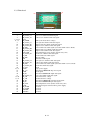
1
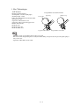
i550 / i850 / i950
Service Manual
Revision 0
QY8-1385-000
COPYRIGHT © 2002 CANON INC. CANON i550/i850/i950 0902 GR
6FRSH
This manual has been issued by Canon Inc. to provide the service technicians of this product with the
information necessary for qualified persons to learn technical theory, maintenance, and repair of products.
This manual covers information applicable in all localities where this product is sold. For this reason, this
manual may contain information that is not applicable to your locality.
5HYLVLRQ
This manual could include technical inaccuracies or typographical errors due to improvements or changes
made to this product. When changes are made to the contents of this manual, Canon will release technical
information as the need arises. When substantial changes are made to the contents of this manual over a long
or short period, Canon will issue a revised edition of this manual.
The following do not apply if they do not conform to the laws or regulations of the country where this manual or
product is used.
7UDGHPDUNV
Product and brand names appearing in this manual are registered trademarks or trademarks of the respective
holders.
&RS\ULJKW
All rights reserved. No part of this manual may be reproduced in any form or by any means or translated into
another language without the written permission of Canon Inc., except in the case of internal business use.
Copyright © 2002 by Canon Inc.
CANON INC.
i Printer Technical Support Dept. 11, 21
16-1, Shimonoge 3-chome, Takatsu-ku, Kawasaki, Kanagawa 213-8512, Japan
I. Manual Outline
This manual is divided into the following three parts to provide information necessary to service the i550, i850,
and i950.
Part 1: Maintenance
This part describes information necessary for troubleshooting the i550, i850, and i950.
Part 2: Technical Reference
This part provides description of new technologies, etc., used in the i550, i850, and i950.
Part 3: Appendix
This part contains block diagrams, pin layouts, and product specification lists.
Reference
This manual does not provide sufficient information for disassembly and assembly.
Refer to the figures in the separate parts catalogue.
II. Table of Contents
Page
Part 1: Maintenance
1-1
1-2
1-5
1-5
1-5
1-5
1-5
1-5
1-6
1-6
1-7
1-7
1-7
1-8
1-9
1-9
1-9
1 - 11
1 - 14
1 - 15
1 - 15
1. Periodic Replacement/Periodic Inspection/Life
2. Troubleshooting List by Error/Symptom
3. Repair Details
3.1 Precautions
3.1.1 Precautions regarding ink stains
3.1.2 Precautions when releasing the carriage lock
3.1.3 Precautions when removing/installing tap screws
3.1.4 Code strip handling precautions
3.1.5 Do not loosen or remove red screws
3.1.6 Logic board removal precautions
3.2 Adjustments
3.2.1 Waste ink counter setting
3.2.2 Resetting EEPROM
3.2.3 Applying grease (oil)
3.3 Settings
3.3.1 Standalone printer operation
3.3.2 Service mode functions
3.3.3 Test print sample
3.3.4 Printing EEPROM information
3.4 Verification
4. Printer Transportation Method
Page
Part 2: Technical Reference
2-1
2-2
2-3
2-6
1. New Technologies
2. Cleaning Mode and Suction Amount
3. Print Mode List
4. FAQ
Page
Part 3:
3-1
3-3
3-3
3-8
3 - 12
3 - 16
1. Block Diagram
2. Connector Locations and Pin Layout
2.1 i550 Connector Locations and Pin Layout
2.2 i850 Connector Locations and Pin Layout
2.3 i950 Connector Locations and Pin Layout
2.4 Product Specification List
Appendix
3DUW
Maintenance
1. Periodic Replacement/Periodic Inspection/Life
<Periodic replacement>
Level
User
Service personnel
Periodic replacement
None
None
<Periodic inspection>
Level
User
Service personnel
Periodic inspection
None
None
<Life>
(1) Paper feed count:
- Main body <i550 / i850>
30,000 sheets (monochrome, 1,500 character standard text pattern printing)
10,000 sheets (printing each color at 7.5% duty)
<i950>
10,000 sheets (Pattern printing each color at 7.5% duty)
(2) 5 years
The life of this product is (1) or (2) above, which ever comes first.
- Print head life <i550 / i850>
30,000 sheets: monochrome printing (1,500 character standard text pattern printing)
10,000 sheets: color printing (pattern printing each color at 7.5% duty)
<i950>
9,000 sheets: Pattern printing each color at 7.5% duty (BK, Y, M, C) : 5,000 sheets
1,500 character standard pattern printing (BK) : 2,000 sheets
Photo image (6 colors) : 2,000 sheets
<Serial number location>
Carriage ribbon cable holder (visible when access cover is opened)
1-1
Orange Flash
(Error Code)
2
(1000)
3
(1300)
4
(1601,1611,
1612,1613
1634*1,1635*1)
6
(1401)
7
(1403,1405
1485*1)
8
(1700)
*1: i950 only
Install head or replace head/logic
board/carriage
Replace head/carriage/logic board
Replace waste ink absorber
No cartridge error
Waste ink full warning
Cartridge error
1-2
Remove paper and press the Resume
key
Replace and set ink tank(s)
Paper jam error
No ink error
Set paper and press the Resume key
Action
No paper error
Error description
Error codes are displayed on the monitor of the connected computer.
Start the status monitor on the host computer in order to display the error codes.
7DEOH2SHUDWRU&DOO(UURUV
2. Troubleshooting List by Error/Symptom
Be careful of ink stains
Be careful of electrostatic damage
Be careful of ink stains
Be careful of electrostatic damage
- Be careful of ink stains
- Be careful of electrostatic damage
-
- Be careful that spurs do not come off
when removing paper
- Be careful of ink stains
Assembly/disassembly precautions
Set waste ink counter (see 3.2.1)*1
Set destination (see 3.3.2)
Set waste ink counter (see 3.2.1)*1
Set destination (see 3.3.2)
- Clear EEPROM (see 3.2.2)
-
Adjustment
Replace logic board
Replace head/logic board
RAM error *2
Other hardware error *2
Replace logic board
Replace logic board
ROM error *2
RAM error
Replace logic board
EEPROM error
*1: i550/i850 only *2: i950 only
LED ON*1
(6800)
Replace head/logic board
Replace waste ink absorber/logic
board
Waste ink full error
Head overheating error
Replace logic board
Internal temperature error *1
8
(5200)
9
(6800)
10
(6100)
11
(6300)
13
Replace purge unit/logic board
Recovery system error
4
(5C00)
6
(5400)
7
(5B00)
Replace code wheel/LF encoder
unit/logic board
Replace code strip/carriage
unit/logic board
Action
LF error
CR error
Error description
3
(6000)
Cyclical flash
(Error Code)
2
(5100)
Error messages are displayed on the monitor of the connected computer.
Start the status monitor on the host computer in order to display the error messages.
7DEOH6HUYLFH&DOO(UURUV
Be careful of ink stains
Be careful of electrostatic damage
Do not loosen or remove red screws
Be careful of ink stains
Be careful of electrostatic damage
Be careful of electrostatic damage
Be careful of electrostatic damage
Do not loosen or remove red screws
There must be no grease on code strip
Be careful of electrostatic damage
Do not loosen or remove red screws
There must be no grease on code strip
Be careful of ink stains
Be careful of electrostatic damage
Be careful of electrostatic damage
1-3
- Be careful of ink stains
- Be careful of electrostatic damage
- Be careful of electrostatic damage
- Be careful of electrostatic damage
- Be careful of electrostatic damage
-
-
Assembly/disassembly precautions
-
Apply grease (see 3.2.3)
Set waste ink counter (see 3.2.1)*2
Set destination (see 3.3.2)
Apply grease (see 3.2.3)
Set waste ink counter (see 3.2.1)*2
Set destination (see 3.3.2)
Set waste ink counter (see 3.2.1)*2
Set destination (see 3.3.2)
Set waste ink counter (see 3.2.1)*2
Set destination (see 3.3.2)
Clear EEPROM (see 3.2.2)
Set waste ink counter (see 3.2.1)*2
Set destination (see 3.3.2)
Set waste ink counter (see 3.2.1)*2
Set destination (see 3.3.2)
Set waste ink counter (see 3.2.1)*2
Set destination (see 3.3.2)
Set waste ink counter (see 3.2.1)*2
Set destination (see 3.3.2)
Set waste ink counter (see 3.2.1)*2
Set destination (see 3.3.2)
Set waste ink counter (see 3.2.1)*2
Set destination (see 3.3.2)
Set waste ink counter (see 3.2.1)*2
Set destination (see 3.3.2)
Adjustment
*1: i950 only
Does not print at all/no color
Print
result
error
Spur tracks appear
Missing lines
Bad coloring
Printing overlapped
Black ink not ejected
Figures/characters stretched
Scratches or white streaks
appear even after cleaning
Lines not in data printed
Paper is soiled
Multiple sheets are fed
together
Paper does not feed
Paper skews
Symptom
Does not power on
Power goes off immediately
after power on
Head not recognized
Does not return to home
position
Abnormal noise
Printing stops before
completing
Feed error
Operation
error
7DEOH7URXEOHVKRRWLQJE\6\PSWRP
Be careful of ink stains
Do not loosen or remove red screws
There must be no grease on code strip
Be careful of ink stains
- Be careful of ink stains
- Do not loosen or remove red screws
- There must be no grease on code strip
- Be careful not to bend spur tips
- Be careful of ink stains
- Be careful of ink stains
-
- Be careful of ink stains
- Be careful of electrostatic damage
- Be careful that spurs do not come off
1-4
Pass few sheets of paper/clean paper path
with cloth or replace platen absorber/
purge unit
Replace platen unit
Replace ink tank/head
Replace print head
Replace platen unit
Refresh print head/replace print head
Clean grease on code strip or replace
carriage unit
Remove/install print head or replace print
head/ink tank/purge unit/carriage unit
Remove debris/replace ASF
Remove debris/adjust paper guide
position
Replace print head/ink tank/logic
board/purge unit
Replace ASF
- Be careful of electrostatic damage
- Be careful of ink stains
- Do not loosen or remove red screws
- There must be no grease on code strip
Remove/install print head or replace print
head/carriage unit
Remove debris/correct loose parts
Replace logic board
Assembly/disassembly precautions
- Be careful of electrostatic damage
Action
Replace AC adapter/logic board
- Set waste ink counter (see
3.2.1)*1
- Set destination (see 3.3.2)
- Set waste ink counter (see
3.2.1)*1
- Set destination (see 3.3.2)
Adjustment
- Set waste ink counter (see
3.2.1)*1
- Set destination (see 3.3.2)
3. Repair Details
3.1 Precautions
3.1.1 Precautions regarding ink stains
Be careful not to touch the ink path and stain the printer, work bench, hand, or clothes with ink during repair.
3.1.2 Precautions when releasing the carriage lock
The carriage locks at the capping position when the power is turned off normally, with the cartridge installed
in the carriage.
If the printer does not operate normally, manually release the carriage lock as necessary.
Turn the gear in the figure in the direction of the arrow to release the carriage lock.
Figure 1-1 Releasing Carriage Lock
3.1.3 Precautions when removing/installing tap screws
Tap screws are used to secure the printer unit and the base. When a tap screw is removed, mold scrap may
adhere to the screw threads, which can damage the mold-side threads when the tap-screw is re-fastened.
Therefore, remove the mold scraps adhered to the screw or use a new screw when re-installing.
3.1.4 Code strip handling precautions
1) Do not apply grease to the code strip.
If grease contacts the code strip, the code strip slits may become unreadable, causing errors.
If grease contacts the code strip, wipe off thoroughly with alcohol. 2) Do not bend or scratch the code strip.
Replace the code strip if it is scratched, or bent until it is white. 3) Extend the leaf spring when attaching or removing the code strip.
The code strip is held taut and secured by the leaf spring.
Note that if the spring is stretched too far in the direction of the arrow, it will not properly re-secure the
code strip.
Be careful not to pull too hard on the code strip when installing or removing it.
Figure 1-2 Code Strip
1-5
3.1.5 Do not loosen or remove red screws
Do not loosen or remove the red screws below because they cannot be adjusted in the field.
(a) Head gap adjustment red screw x 2 (one on each side)
(b) Paper feed motor anchor screw x 2
D
E
D
Figure 1-3 Do Not Loosen or Remove Red Screws
3.1.6 Logic board removal precautions
The Logic Board can be damaged due to short circuiting during removal.
When removing the Logic Board, unplug the power cord and allow the unit to sit for approximately 1 minute
to discharge the capacitor.
1-6
3.2 Adjustments
3.2.1 Waste ink counter setting
(1) When replacing the logic board, replace the waste ink absorber, depending on the value of the waste ink
counter.
Use the following table as a guide to replacement.
7DEOH:DVWH,QN$EVRUEHU5HSODFHPHQW7LPLQJDQG:DVWH,QN&RXQWHU6HWWLQJ
Waste ink counter setting
i550 / i850 / i950
0-7
Clear waste ink counter
7 - 100
Clear waste ink counter and replace waste ink absorber
Print the EEPROM information in service mode to check the waste ink count.
(2) PIXUS 950i waste ink counter clearing method
After selecting the waste ink counter setting via the service mode function (for details, refer to 3.3.2), press
the Power button. Then, without pressing the Resume button, press the Power button once again.
3.2.2 Resetting EEPROM
When the EEPROM is reset, the entire contents of the EEPROM is cleared (excluding the following items).
<i550 / i850>
- USB-S/N
- Waste ink counter
<i950>
- USB-S/N
1-7
3.2.3 Applying grease (oil)
After disassembly/assembly, apply special tool grease at the locations shown below.
Apply a thin layer of grease using a flat brush.
Do not apply
(100mm max)
3
1
2
Figure 1-4 Applying Grease
i550 / i850
Location
1. Carriage shaft circumference
2. CR slider, selector lever sliding surface
Grease/Oil name
Floil KG107A
Floil KG107A
Amount
200 - 400mg
27.5±7.5 mg
i950
Location
1. Carriage shaft circumference
2. CR slider, selector lever sliding surface
3. Carriage oil pad*1
Grease/Oil name
EU-1
Floil KG107A
EU-1
Amount
80±30 mg
27.5±7.5 mg
100±10 mg
1-8
3.3 Settings
3.3.1 Standalone printer operation
This printer has an offline mode which allows the printer operation without connection to a computer.
With the printer powered ON, press and hold the Resume button until the green indicator flashes the specified
number of times to start each operation, and then release the Resume button to execute the function.
Operation
Remark
LED flash
1
Cleaning
2
Nozzle check pattern print Set A4 size or larger paper and print
3
Roller cleaning
Clean without paper and then clean with paper (A4 or larger)
set
3.3.2 Service mode functions
This printer has a Service mode to set service only settings and output test prints. The Service mode can be
entered using the control panel.
<Service mode operation list>
1) With the printer power OFF, while pressing the Resume button, press the Power button. (Do not release the
power button.)
2) While pressing the Power button, release the Resume button, press the Resume button again twice, and then
release the Resume button and Power button.
3) The green indicator flashes during initialization.
When the indicator stops flashing and remains on, press the Resume button the specified number of times to
select the function.
(The indicator toggles between orange and green each time the Resume button is pressed.)
4) After selecting the function, press the Power button, and the green indicator will light, and the function will
be executed.
<i550/i850 Service Mode>
Count
0
LED
Green
Power off
Function
1
2
Orange
Green
Service test print
EEPROM information print
3
Orange
EEPROM initialization
4
5
Green
Orange
Clear waste ink counter
Destination setting
6
7
8
9
10
Green
Orange
Green
Orange
Green
Head refreshing
Remark
When there is no head, the carriage returns to the home
position and locks
Destination is set to overseas during EEPROM
initialization
Clear waste ink counter
After selecting a function press the Resume button
(1: Overseas, 2: Domestic)
Clean both BK/CL ink
Not used for service
Not used for service
Not used for service
Return to selection menu
1-9
<i950 Service Mode>
Count
0
LED
Green
Function
Power off
1
2
Orange
Green
3
Orange
Service test print
EEPROM information
print
EEPROM initialization
4
Green
5
Orange
6
Green
7
Orange
8
9
10
11
12
13
Green
Orange
Green
Orange
Green
Orange
Waste ink counter
setting
Destination setting
Default registration
adjustment pattern
Default registration
adjustment setting
Roller cleaning
LF check pattern
Return to selection
menu
(Press the Power button to cancel during printing)
Remark
When there is no head, the carriage returns to the home
position and locks
Destination becomes overseas during EEPROM
initialization
Clear waste ink counter (see 3.2.1 Waste ink counter
setting)
After selecting a function press the Resume button
(0: Domestic, 1: Overseas)
Not used for service
Not used for service
ASF paper feed roller cleaning (rotate ASF 10 times)
Not used for service
Not used for service
Not used for service
Not used for service
1 - 10
3.3.3 Test print sample
(1) i550
Test print sample
Figure 1-5 Service Test Print Sample (i550)
1 - 11
(1) i850
Test print sample
Figure 1-6 Service Test Print Sample (i850)
1 - 12
(1) i950
Test print sample
Figure 1-7 Service Test Print Sample (i950)
1 - 13
3.3.4 Printing EEPROM information
EEPROM print prints the content of the printer internal EEPROM and the EEPROM in the print head.
The resulting output can be used to check the printer settings and data.
<i550 / i850>
[Print Example]
i550 V0.01 D=000.0 Page=00000 CH=00000 Bk(00) Cl(+2)
Head TempBK=18.5 Head TempC=17.5 Env Temp=30.0 FF(3F 3F 3F)
PC(M=0000 R=0000 T=0000 D=0000 C=0000) Bk=00000 C=00000 M=00000 Y=00000
WP=0000 IC(BK=0 C=0 M=1 Y=0) CT(BK=00000 Y=00000 M=00000 C=00000)
USB=(BCDEFG) ER(TIME=2002/00/00-00:00 ER0=1000 ER1=5100 ER2=5200 ER3=1000)
UR(C=000 BK=000 BK-C=+02 Y=000 M=000 G=+01 H=-01) CDR=(-00005,-000029) *1
ST=2002/00/00-00:00 PWC(S=00000 h=00000) CN(USB=1 1284=0) EDGE=00000
PAGE(ALL=00000 PP=00000 HR=00000 GP=00000 MP=00000 SP=00000 PC=00000 OTHER=00000)
-----------------------------------------------------------------------------------------[Print Item Name]
1: Model 2: ROM version 3: Waste ink capacity 4: Print count 5: Head installation count 6: Bidirectional
registration (black, color) 7: Head temperature (black, color) 8: Internal temperature 9: Process inspection
information 10: Recovery operation count (MRTDC) 11: Dot count (Bk, C, M, Y) 12: Wipe count 13: Ink
(Yes=0, No=1) 14: Ink removal/installation count (Bk, Y, M, C) 15: USB serial (6 characters) 16: Operator
call/service call log (time, log 0.1.2.3) 17: User registration adjustment value: odd even (C C, Bk Bk,
Bk C, Y Y, M Ye, G, H) 18: CDR compensation*1 19: Installed date 20: Power on count (hard/soft)
21: Connection I/F (USB1284) 22: Borderless printing count 23: Paper pass count (all, plain paper, high
resolution paper, glossy photo paper, matte photo paper, photo paper plus glossy, post card, others)
Ù Ù
Ù
Ù
Ù
Ù
*1 Not used because it is for PIXUS 850i Japanese model only
<i950>
[Print Example]
i950 V0.01 S/N(000000) BK(-1) D=000.00% FA=3F 3F 3F CDR(000,000) *1
CH=0000 CT(C=0000 CL=0000 K=0000 Y=0000 ML=0000 M=0000
Page=0000 ED(00000/00000/00000) OE(00000/00000) CD=00000*1
SV(0000/0000) OP(0000/0000/0000)
UR(Ce=+01 Co=-01 CLe=+01 CLo=+01 Ke=+01 Ko=+01 Ye=+01 Yo=+01)
(MLe=+10 MLo=+10 Me=+10 Mo=+10)
DIR((C=000 LC=000 K=000 Y=000 ML=000 M=000)
PT=2002/06/11-10:30 ST=2002/06/11 LP=2002/06/11 PD=0 IF=0 0 AP=000
DC(C=000 CL=000 K=000 Y=000 ML=000 M=000)
PC(5D=00000 DC=00000 MN=00000 20D=000 RF=000 SH=000) OT=000
-----------------------------------------------------------------------------------------[Print Item Name]
1: Model 2: ROM version 3: Serial no. 4: Bidirectional registration 5: Waste ink capacity 6: Process inspection
information 7: CDR compensation*1 8: Head installation count 9: Ink removal/installation count (C, CL, K, Y,
ML, M) 10: Total paper pass count 11: Paper pass count (normal/special/post card) 12: No border paper pass
count (post card/other) 13: CDR paper pass count*1 14: Service call log (log 0.1) 15: Operator call log (log 0.1.2)
16: User registration adjustment value (Ce, Co, Cle, Clo, Ke, Ko, Ye, Yo)
17: User registration adjustment value (Mle, MLo, Me, Mo) 18: Bidirectional registration (C, LC, K, Y, ML, M)
19: Last suction time 20: Installed time 21: Last suction date 22: Page delay 23: USB connection log (1.1/2.0) 24:
Auto power on 25: Dot count (C, CL, K, Y, ML, M) 26: Suction count (5 day timer/dot count/manual/20 day
timer/refresh/shipment suction/cap open)
*1 Not used - reserved for PIXUS 950i Japanese model only
1 - 14
3.4 Verification
(1) Print the nozzle check pattern when replacing the print head, sheet feeder unit, purge unit, or carriage unit.
(2) Check the connection with PC and print the nozzle check pattern when replacing the PCB.
4. Printer Transportation Method
This section describes the procedures for transporting the printer (for example, when returning after repair).
(1) Keep the print head in the carriage.
(2) Turn off the power and ensure that it is properly capped at home position.
If the print head is left alone by itself, the ink may solidify.
Therefore, keep the print head (with ink tank) in the carriage even when transporting.
Also, secure the carriage at home position to prevent it from moving and applying stress to the encoder film
during transportation.
If the print head must be transported by itself, perform the following:
1. Install ink tanks for each color. (to prevent nozzles from drying)
2. Install the orange protective cap on the print head.
(to prevent damage to the print head due to shock etc.)
1 - 15
3DUW
Technical Reference
1. New Technologies
ASF features
-
Retard separation method
Stacking limit: 150 sheets (SK paper)
Stacking height: 13mm
Paper feed roller diameter: φ20 round roller
(through axis type)
Separation roller diameter: φ14
Separation roller retracts after paper feed
Return claw structure
Reduced noise
Reduced paper curl
Reduced double feed
Torque limiter retard roller method
Feed roller
[Separate]
Separator roller rubber
[Single feed]
Torque limiter retard roller
- May skew easily, as the pickup roller is only on one side.
- The sheet feeder unit pressure plate is easily deformed during storage because the pressure plate spring is
only on one side. - Separation roller rubber wears easily.
2-1
2. Cleaning Mode and Suction Amount
Print head cleaning is performed effectively and efficiently depending on conditions in order to prevent print
errors caused by bubble, dust, or ink clogging.
Cleaning is performed before starting to print except at the following timing:
Dot count suction: Performed after paper ejection
Manual cleaning/refreshing: Performed during operation
Unit delivery: Performed when access cover is closed
Table 2-1 Cleaning Mode List (i550/i850)
Condition
Manual cleaning
Refreshing
Timer suction
Long timer suction I
Long timer suction II
Long timer suction III
Long timer suction IV
Dot count suction
When replacing print head
When replacing ink tank
At delivery or during first
head position adjustment
Uncapped when Soft ON
Details
Panel operation and printer driver operation
Printer driver operation
If 24 to 336 hours have elapsed since previous suction (BK).
If 120 to 336 hours have elapsed since previous suction.
If 336 hours or more have elapsed since previous suction.
If 1080 hours or more have elapsed since previous suction.
If 2160 hours or more have elapsed since previous suction.
If 4320 hours or more have elapsed since previous suction.
When prescribed dot count since the last suction is reached
When print head is removed/installed
Ink sensor detects that ink is present in the ink tank
That is the state changed from no ink in the ink tank
Suction when head is first installed after factory shipment
When capping was not performed properly during last power
off
Suction
amount
BK/CL (g)
0.14/0.36
1.58/0.72
0.14/0.36
0.45/0.72
0.78/0.72
1.58/0.72
1.58/0.72
0.14/0.36
0.45/1.08
1.58/0.72
0.45/1.08
0.30/0.72
Table 2-2 Cleaning Mode List (i950)
Condition
Manual cleaning
Refreshing
120 hour timer suction
480 hour timer suction
Dot count suction
When replacing print head
When replacing ink tank
At delivery
Uncapped when Soft ON
After hardware power ON
(If time is not checked)
Cap open
(When cap has been open
for 30 minutes or more)
Details
Panel operation and printer driver operation
Printer driver operation
If 120 to 480 hours have elapsed since previous suction.
If 480 hours or more have elapsed since previous suction.
When prescribed dot count since the last suction is reached
When print head is removed/installed
Ink sensor detects that ink is present in the ink tank
That is the state changed from no ink in the ink tank
Suction when head is first installed after factory shipment
Suction
amount
BK/CL (g)
0.89
2.68
0.89
1.34
1.1
2.68
1.34
2.68
When capping was not performed properly during last power
off
Standalone test print etc.
2.68
When uncapped for more than 30 minutes during printing or
in standby
0.89
*1 Suction amount is the total for 6 colors
2-2
1.34
3. Print Mode List
Table 2-3 Print Mode List (i550)
Paper type
Passes
Pig/YMC
Resolution
Print quality
High
Passes
resolution
Pig/YMC
paper
Resolution
HR-101S
Print quality
Photo paper Passes
pro
Pig/YMC
PR-101
Resolution
Print quality
Glossy photo Passes
paper
Pig/YMC
GP-301
Resolution
Print quality
Ink jet
Passes
Post card
Pig/YMC
Envelope
Resolution
Plain paper
Post card
Glossy film
HG-201
T shirt
transfer
paper
TR-201
OHP film
CF-102
Print quality
Passes
Pig/YMC
Resolution
Print quality
Passes
Pig/YMC
Resolution
Print quality
Passes
Pig/YMC
Resolution
Print quality
Passes
Pig/YMC
Resolution
Print quality
Quality 5
1 pass
Pig
300x300
Fast
Quality 4
SDVVHV
3LJ
[
6WDQGDUG
2 passes
YMC
CM:1200x1200
Y:600x600
---
SDVVHV
<0&
&0[
%.<[
6WDQGDUG
SDVVHV
3LJ<0&
&0[
%.<[
6WDQGDUG
Quality 3
1, 4 passes
Pig
600x600
---
SDVVHV
<0&
[
6WDQGDUG
SDVVHV
<0&
[
6WDQGDUG
Passes
Pig/YMC
Resolution
Print quality
Photo paper Passes
plus glossy
Pig/YMC
PP-101
Resolution
Print quality
* Bold items are default settings
2-3
Quality 1
High
SDVVHV
<0&
[
6WDQGDUG
6 passes
YMC
1200x1200
High
6 passes
YMC
1200x1200
High
12 passes
YMC
2400x1200
---
SDVVHV
<0&
[
6WDQGDUG
6 passes
YMC
1200x1200
High
4 passes
YMC
1200x1200
High
6 passes
Pig+YMC
BK: 600x600
CL:1200x1200
High
SDVVHV
<0&
[
+LJK
SDVVHV
3LJ<0&
%.[
&/[
6WDQGDUG
SDVVHV
<0&
[
6WDQGDUG
Matte photo
paper
MP-101
Quality 2
4 passes
Pig
600x600
High
6 passes
YMC
1200x1200
6 passes
Pig+YMC
BK:600x600
CL:1200x1200
High
6 passes
YMC
1200x1200
High
SDVVHV
<0&
[
6WDQGDUG
6 passes
YMC
1200x1200
High
Table 2-4 Print Mode List (i850)
Paper type
Passes
Pig/YMC
Resolution
Print quality
High
Passes
resolution
Pig/YMC
paper
Resolution
HR-101S
Print quality
Photo paper
Passes
pro
Pig/YMC
PR-101
Resolution
Print quality
Glossy photo
Passes
paper
Pig/YMC
GP-301
Resolution
Print quality
Ink jet
Passes
Post card
Pig/YMC
Resolution
Plain paper
Post card
Glossy film
HG-201
T shirt transfer
paper
TR-201
OHP film
CF-102
Print quality
Passes
Pig/YMC
Resolution
Print quality
Passes
Pig/YMC
Resolution
Print quality
Passes
Pig/YMC
Resolution
Print quality
Passes
Pig/YMC
Resolution
Quality 5
1 pass
Pig
600x600
Fast
Quality 4
SDVV
3LJ
[
6WDQGDUG
2 passes
YMC
600x600
---
SDVVHV
<0&
%.[
&/[
6WDQGDUG
SDVVHV
3LJ<0&
%.[
&/[
6WDQGDUG
Print quality
Passes
Pig/YMC
Resolution
Print quality
Photo paper
Passes
plus glossy
Pig/YMC
PP-101
Resolution
Print quality
* Bold items are default settings
Matte photo
paper
MP-101
2-4
Quality 3
1, 4 passes
Pig
600x600
---
SDVVHV
<0&
[
6WDQGDUG
SDVVHV
<0&
[
6WDQGDUG
SDVVHV
<0&
[
6WDQGDUG
Quality 2
4 passes
Pig
600x600
High
6 passes
YMC
1200x1200
High
6 passes
YMC
1200x1200
High
6 passes
YMC
1200x1200
High
4 passes
YMC
BK:600x600
CL:1200x1200
High
4 passes
Pig+YMC
BK:600x600
CL:1200x1200
High
SDVVHV
<0&
[
6WDQGDUG
SDVVHV
<0&
[
+LJK
SDVVHV
3LJ<0&
%.[
&/[
6WDQGDUG
SDVVHV
<0&
[
6WDQGDUG
SDVVHV
<0&
[
6WDQGDUG
6 passes
YMC
1200x1200
High
6 passes
Pig+YMC
BK:600x600
CL:1200x1200
High
6 passes
YMC
1200x1200
High
6 passes
YMC
1200x1200
High
Quality 1
16 passes
YMC
4800x1200
--12 passes
YMC
2400x1200
---
Table 2-5 Print Mode List (i950)
Paper type
Passes
Number of
colors
Resolution
Print quality
High resolution
Passes
paper
Pig/YMC
HR-101S
Resolution
Print quality
Photo paper pro
Passes
PR-101
Pig/YMC
Resolution
Print quality
Glossy photo
Passes
paper
Pig/YMC
GP-301
Resolution
Print quality
Ink jet
Passes
Post card
Pig/YMC
Resolution
Print quality
Glossy film
Passes
HG-201
Pig/YMC
Resolution
Print quality
T shirt transfer
Passes
paper
Pig/YMC
TR-201
Resolution
Print quality
OHP film
Passes
CF-102
Pig/YMC
Resolution
Print quality
Matte photo
Passes
paper
Pig/YMC
MP-101
Resolution
Print quality
Photo paper plus Passes
glossy
Pig/YMC
PP-101
Resolution
Print quality
* Bold items are default settings
Plain paper
Post card
Envelope
Quality 5
1 pass
4 colors
1200x1200
Fast
Quality 4
SDVVHV
FRORUV
[
6WDQGDUG
Quality 3
4 passes
6 colors
2400x1200
---
Quality 2
SDVVHV
FRORUV
[
+LJK
SDVVHV
FRORUV
[
+LJK
8 passes
6 colors
2400x1200
--8 passes
6 colors
4800x1200
---
4 passes
6 colors
2400x1200
High
8 passes
6 colors
4800x1200
---
4 passes
6 colors
2400x1200
Fast
SDVVHV
FRORUV
[
6WDQGDUG
SDVVHV
FRORUV
[
6WDQGDUG
SDVVHV
FRORUV
[
6WDQGDUG
SDVVHV
FRORUV
[
6WDQGDUG
4 passes
4 colors
2400x1200
Fast
2-5
Quality 1
8 passes
6 colors
2400x1200
---
SDVVHV
FRORUV
[
+LJK
SDVVHV
FRORUV
[
+LJK
8 passes
6 colors
2400x1200
High
SDVVHV
FRORUV
[
+LJK
Model
Cause
Head friction
diagonally
The final sheet of PR-101 paper moves
Ink mist
All models
All models
All models
Action
(2) Head friction is caused by paper curl.
printing support.
2-6
(1) Paper float cannot be suppressed due to borderless
only one paper.
and the pressure of the side guide is strong when there is
Paper is skewed easily because of the single roller structure
(2) Control carriage overrun during L format borderless printing
Set and print after correcting paper curl.
Set an extra sheet of plain paper under the last paper.
Note: Do not touch the coat strip or borderless absorber.
site when mists appear.
completely. Therefore, the platen rib is to be cleaned with a cotton swab on
Above three measures were taken, but ink mist could not be eliminated
(3) Change default run over during borderless printing.
(1) Change shape of platen rib
Ink mists are generated during borderless paper printing and
Banner Paper
Refer to User’s Guide, Print Media,
printing with the ejection tray stored.
Photo Paper Pro PR-101
Change specification and description in user manual to perform banner
Refer to User’s Guide, Print Media,
Manual description
time when stacking multiple sheets of paper.
Change specification in user manual to set up to 10 sheets of paper one at a
Left as is, as the spur mark is very faint.
Spur direction was changed, but faint spur marks remain.
fed.
Left as is, as the problem is solved after 2 or 3 sheets of normal paper are
Schedule: End of Oct. 2002 (running change basis)
prevent pickup roller deformation.
Increase the strength of rubber material by changing it frequently in order to
attaches to the platen rib.
head friction.
it to buckle, affecting paper at the print area, resulting in
Banner paper is folded at the tip of the ejection tray causing
Head friction when printing on banner
paper
together resulting in feed overlap.
multiple papers are stacked
All models
All models
PR-101 Feed overlap occurs when
Static electricity between papers causes paper to stick
Spur and holder burrs cause marks.
PIXUS550i
Spur marks (GP-301)
The pinch roller oil adheres to the surface of the paper
causing skewed feeding or feed error.
When more print media is set, the separator roller slips
leaving pinch roller marks.
PIXUS550i
PIXUS850i
PIXUS550i
(PR-101/GP-301)
Pinch roller marks
Paper moves diagonally/feed error
Problems
Table 2-6 PIXUS 550i/PIXUS 850i/PIXUS 950i Trouble
)$4
3DUW
Appendix
1. Block Diagram
i550 Block Diagram
IC111
MAIN PWB
ASIC
< KOUMEI >
X101
48MHz
CN506
Ink
Sensor
SSCG
Serial
I/F
CN201
CR PWB
CN01
SW401
Power
Button
Temp
Sensor
Q222
SW402
CPU
Resume
Button
FET
VH
IC211
TH1
DI
Sensor
AMP
SW403
IC471
Door
Sensor
HEAD Unit
EEPROM
2Kbit
IC101S
CN202
EEPROM
MASKROM
8Mbit
CN301
CN02
USB
I/F
3/6MHz
CR
Encoder
CN302
CN507
IEEE1284
I/F
PG
Sensor
5MHz
IC102
CN504
IC541
CR
Motor
48MHz
SDRAM
16Mbit
CR/LF
Motor
Driver
UDL
LED401
2Color
LED
Tr
CN505
LF
Motor
PS411
PE
Sensor
CN408
LF
Encoder
IC511
ASF
Sensor
CN503
ASF/PG
Motor
Driver
Vcc
VH
PG
Motor
Tr
Tr
VM
ASF
Motor
CN502
CN501
2.5v
Vcc
3.3v
Resume
VH
VM
5v
19v
27v
Power Unit
i850 Block Diagram
Ink
Sensor
MAIN PCB
UART
CR PCB
Temp
Sensor
AD
Power Button
Resume Button
AMP
CPU
Block
Door
Sensor
EEPROM
2Kbit
MASKROM
8Mbit
HEAD
48MHz
CD-R
Sensor
CR
Encoder
USB
IP
CD
Motor
Driver
IEEE1284
I/F
SDRAM
64Mbit
IP
Block
PE
Sensor
2Color
LED
Step
Motor
Driver
Motor
Driver
3.3V
2.5V
RESX
REG in DC Dri.
Diode
Sensor
EEPROM
SSCG
USB
I/F
HEAD Unit
CR
Motor
LF
Motor
LF
Encoder
ASF
Motor
ASF
Sensor
PG
Motor
PG
Sensor
+5V
VH
VM
PW CONT
CD-R
Motor
5V
24V
27V
Power Unit
3-1
Guide
Sensor
i950 Block Diagram
USB 2.0
Chip
USB 2.0
Chip Clock
USB
I/F
MASKROM
16Mbit
ASIC
MPU
Clock
BJ
HEAD
Power
Button
Photo
Sensor
Resume
Button
LED
Door
Sensor
EEPROM
2Kbit
From
Ink Sensor
USB
I/F
Auto Sheet
Feed Sensor
Motor IC
Paper End
Sensor
CR
Motor
LF
Motor
Motor IC
Voltage
Regulator
ASF
Motor
PG
Motor
Voltage
Regulator
SW R
3-2
Motor IC
Lift Up
Motor
2. Connector Locations and Pin Layout
2.1 i550 Connector Location and Pin Layout
2.1.1 Logic board
CN301
CN504 CN507
CN202
CN502
CN408
CN503
CN201
CN501
CN302
Figure 3-1 Logic Board
CN201 (Carriage ribbon cable connector)
Pin No.
1
2
3
4
5-6
7
8
9 - 12
13 - 16
17 - 21
22 - 25
Signal Name
DIODE_GND
DIA1
DIK0
THERMO
HVDD
HVSS
HVH
HVH
HVH
H_GND
H_GND
Function
BK/COL diode sensor cathode
COL diode sensor anode
BK diode sensor anode
Thermistor signal
3.3V head logic power supply
Logic GND
Head gate power supply
19V head (BK) power supply
19V head (COL) power supply
Head (COL) GND
Head (BK) GND
CN202 (Carriage ribbon cable connector)
Pin No.
1
2
3, 5, 9, 18, 22, 24
4
6
7
8
10
11
12
13
14
15
16
17
19
20
21
23
25
Signal Name
VSEN_3.3V
CR_ENC0
L_GND
CR_ENC1
H_ENB0
H_ENB1
H_ENB2
H_D0
H_D1
H_D2
H_D3
H_D4
H_D5
H_D6
H_D7
H_EEPROM_DIO
H_EEPROM_SK
H_EEPROM_CS
H_CLK
H_LATCH
Function
3.3 V power supply for encoder
Encoder signal phase A
Logic GND
Encoder signal phase B
BK heat enable
COL heat enable
COL heat enable
BK data
BK data
C data
C data
M data
M data
Y data
Y data
Head EEPROM data
Head EEPROM clock
Head EEPROM chip select
Head data transfer clock
Head data latch signal
3-3
CN505
CN506
CN301 (USB interface connector)
Pin No.
1
2
3
4
Signal Name
USB_VBI
USB_DN
USB_DP
GND
Function
Cable power supply
Differential data signal
Differential data signal
GND
CN302 (Parallel interface connector)
Pin No.
1
2-9
10
11
12
13
14
15
16, 17
18
19
20
21
22
23
24
25
26
27
28
29
30
31
32
33
34
35
36
Compatible mode
STROBE
DATA1 - 8
ACKNLG
BUSY
P.E.
SELECT
AUTO FEED XT
N.C
GND
+5.0V
STROBE-RET(GND)
DATA1-RET(GND)
DATA2-RET(GND)
DATA3-RET(GND)
DATA4-RET(GND)
DATA5-RET(GND)
DATA6-RET(GND)
DATA7-RET(GND)
DATA8-RET(GND)
ACKNLG-RET
BUSY-RET
P.E.-RET
INIT
ERROR
GND
N.C
+5.0V
SELECT IN
Nibble mode
HOST CLK
DATA1 - 8
PRT CLK
PRT BUSY
ACK DATA REQ
XFLAG
HOST BUSY
Undefined
GND
VCC
SIGNAL GND
SIGNAL GND
SIGNAL GND
SIGNAL GND
SIGNAL GND
SIGNAL GND
SIGNAL GND
SIGNAL GND
SIGNAL GND
SIGNAL GND
SIGNAL GND
SIGNAL GND
INIT
DATA AVAIL
Undefined
Undefined
Undefined
1284 ACTIVE
CN408 (ASF sensor connector)
Pin No.
1
2
3
Signal Name
VSEN_5V
GND
SNS_ASF
Function
ASF sensor power supply
GND
ASF sensor output signal
CN501 (DC power supply connector)
Pin No.
1
2, 4
3
5
6
Signal Name
+5V
GND
VH
VM
PowerControl
Function
5V power supply
GND
19V power supply
27V power supply
Power consumption control signal
3-4
ECP mode
HOST CLK
DATA1 - 8
PRT CLK
PRT BUSY
ACK DATA REQ
XFLAG
HOST BUSY
Undefined
GND
VCC
SIGNAL GND
SIGNAL GND
SIGNAL GND
SIGNAL GND
SIGNAL GND
SIGNAL GND
SIGNAL GND
SIGNAL GND
SIGNAL GND
SIGNAL GND
SIGNAL GND
SIGNAL GND
INIT
DATA AVAIL
Undefined
Undefined
Undefined
1284 ACTIVE
CN502 (Purge motor connector)
Pin No.
1
2
3
4
Signal Name
PGA
PGB
PGAN
PGBN
Function
PG motor phase A
PG motor phase B
PG motor phase A
PG motor phase B
CN503 (ASF motor connector)
Pin No.
1
2
3
4
Signal Name
ASFA
ASFB
ASFAN
ASFBN
Function
ASF motor phase A
ASF motor phase B
ASF motor phase A
ASF motor phase B
CN504 (Carriage motor connector)
Pin No.
1
2
Signal Name
CRA
CRB
Function
CR motor phase A
CR motor phase B
CN505 (Paper feed motor/LF encoder connector)
Pin No.
1
2
3
4
5
6
Signal Name
LFA
LFB
GND
LF_ENC0
VSEN_3.3V
LF_ENC1
Function
LF motor phase A
LF motor phase B
GND
LF encoder signal phase A
3.3 V power supply for encoder
LF encoder signal phase B
CN506 (Ink sensor connector)
Pin No.
1
2
3
Signal Name
INK_5V
GND
INKS
Function
INK sensor power supply
GND
INK sensor output signal
CN507 (Purge sensor connector)
Pin No.
1
2
3
Signal Name
VSEN_5V
GND
SNS_PG
Function
PG sensor power supply
GND
PG sensor output signal
3-5
2.1.2 Carriage board
CN02
CN01
33
40
8
1
Figure 3-2 Carriage Board
CN01 (Carriage ribbon cable connector)
See Page 3-3 (CN201 Carriage ribbon cable connector)
CN02 (Carriage ribbon cable connector)
See Page 3-3 (CN202 Carriage ribbon cable connector)
CN03 (Print head contact)
Pin No.
1 - 39
Signal Name
Function
See page 3-7 (Print head pin description)
3-6
2.1.3 Print head
40
33
8
1
Figure 3-3 Print Head
Pin No.
1 ,2
3
4
5, 14, 22
6, 7, 8
9
10
11
12
13
15
16
17
18
19
20
21
23
24
25
26
27, 35
28
29
30
31
32, 40
33, 34
36
37
38
39
Signal Name
A_GND
H_D2
H_D6
Function
GND (black heater drive voltage)
Cyan even column nozzle data signal
Yellow even column nozzle data signal
B_GND
DIK0
SUBH0
H_D4
H_ENB1
N.C
H_D5
DIK1
H_D0
H_ENB0
N.C
H_LATCH
SUBH0
H_D7
H_ENB2
H_D1
DIA0
HVDD
H_EEPROM_CS
H_CLK
E_D0
H_D3
B_VH
A_VH
H_EEPROM_SK
E_DI
DIA1
VHT
GND (color heater drive voltage)
Head temperature sensor (diode) cathode side (black)
Black sub heater drive signal
Magenta even column nozzle data signal
Color nozzle heat enable signal (even/odd column odd no. block)
Magenta odd column nozzle data signal
Head temperature sensor (diode) cathode side (color)
Black even column nozzle data signal
Black nozzle heat enable signal
Data latch enable signal
Color sub heater drive signal
Yellow odd column nozzle data signal
Color nozzle heat enable signal (even/odd column even no. block)
Black odd column data signal
Black
Logic power supply
Head internal EEPROM chip select signal
Clock signal
Head internal EEPROM output data signal
Cyan odd column nozzle data signal
Color heater drive voltage
Black heater drive voltage
Head internal EEPROM serial data clock signal
Head internal EEPROM input data signal
Head temperature sensor (diode) anode side (color)
Head internal power transistor drive power
3-7
2.2 i850 Connector Location and Pin Layout
2.2.1 Logic board CN508
CN503
CN501
CN506
CN505
CN421
0
%
0
%
0
%
CN304
Figure 3-4 Logic Board
CN201 (Carriage ribbon cable connector)
Pin No.
1 - 10
11 - 13
14, 19, 20
15
16
17
18
Signal Name
VH
HVDD
GND
H_ENB3
H_ENB0
H_ENB1
H_ENB2
Function
24V head power supply
3.3V head power supply
Logic GND
Heat enable 3
Heat enable 0
Heat enable 1
Heat enable 2
CN202 (Carriage ribbon cable connector)
Pin No.
1
2, 4, 9, 11
3
5,6
7
8
10
12 - 20
Signal Name
DIA0
GND
THERMO
VSEN_3.3V
CR_ENCA
CR_ENCB
SNS_CDR_P
H_GND
Function
Diode sensor anode
Logic GND
Thermistor
3.3V sensor power supply
Encoder signal phase A
Encoder signal phase B
CDR sensor signal
Head GND
CN203 (Carriage ribbon cable connector)
Pin No.
1-8
9 - 12
13
14
15
16, 19
17
18
20
CN305
Signal Name
H_D0 - D7
H_DS0 - DS3
H_EEPROM_DIO
H_EEPROM_SK
H_EEPROM_CS
GND
H_CLK
H_LATCH1
DIA1
Function
Heat data
Heat data
EEPROM data
EEPROM clock
EEPROM chip select
Logic ground
Head transfer clock
Latch signal
Diode sensor anode
CN304 (Parallel interface connector)
See page 3-4 (CN302 Parallel Interface connector)
CN305 (USB interface connector)
See page 3-4 (CN301 USB Interface connector)
3-8
CN402
CN502
CN402 (Ink sensor connector)
Pin No.
1
2
3
Signal Name
POW
GND
INKS
Function
Remaining ink sensor side power supply
GND
Remaining ink sensor output
CN421 (ASF sensor connector)
Pin No.
1
2
3
Signal Name
POW
GND
SNS_ASF
Function
ASF sensor illuminating side power
GND
ASF sensor output
CN501 (DC power supply connector)
Pin No.
1
2, 4, 6
3
5
7
Signal Name
+5V
GND
VH
VMREM
LOW_PW_CONT
Function
GND
Power consumption control
CN502 (Paper feed motor/LF encoder connector)
Pin No.
1
2
3
4
5
6
Signal Name
LFA
LFB
GND
LF_ENCA
VSEN_3.3V
LF_ENCB
Function
LF motor phase A
LF motor phase B
GND
LF encoder signal phase A
3.3 V power for encoder
LF encoder signal phase B
CN503 (Carriage motor connector)
Pin No.
1
2
Signal Name
CRA
CRB
Function
Carriage motor phase A
Carriage motor phase B
CN505 (ASF motor connector)
Pin No.
1
2
3
4
Signal Name
ASFA
ASFB
ASFA
ASFB
Function
ASF motor phase A
ASF motor phase B
ASF motor phase A
ASF motor phase B
CN506 (Purge motor connector)
Pin No.
1
2
3
4
Signal Name
PGA
PGB
PGA
PGB
Function
Purge motor phase A
Purge motor phase B
Purge motor phase A
Purge motor phase B
3-9
CN508 (Purge sensor connector)
Pin No.
1
2
3
Signal Name
POW
GND
SNS_PG
Function
PG sensor illuminating side power supply
GND
PG sensor output
2.2.2 Carriage board
J3
J1
J2
36
44
8
1
Figure 3-5 Carriage Board
J1 (Carriage ribbon cable connector)
See page 3-8 (CN201 Carriage ribbon cable connector pin description)
J2 (Carriage ribbon cable connector)
See page 3-8 (CN202 Carriage ribbon cable connector pin description)
J3 (Carriage ribbon cable connector)
See page 3-8 (CN203 Carriage ribbon cable connector pin description)
J4 (Print head)
Pin No.
1 - 40
Signal Name
Function
See page 3-11 (Print head pin description)
3 - 10
2.2.3 Print head
44
36
8
1
Figure 3-6 Print Head
Pin No.
1, 2
3
4
5, 14, 22
6, 7, 8
9
10
11
12
13
15
16
17
18
19
20
21
23
24
25
26
27, 35
28
29
30
31
32, 40
33, 34
36
37
38
39
41
42
43
44
Signal Name
A_GNDH
B_DATA_C1
B_DATA_Y1
VSS
B_GNDH
B_DATA_C3
B_DATA_M3
B_DATA_M1
B_HE1
B_DATA_M4
B_DATA_M2
A/B_DIK
A_DATA_K1
A_HE
B_HE3
LT
B_DATA_C4
B_DATA_Y2
B_HE2
A_DATA_K2
A_DIA
VDD
E__CS
CLK
E_D0
B_DATA_C2
B_VH
A_VH
E_SK
E_DI
B_DIA1
VHT
B_RANK
A_RANK
CONTB
CONTA
Function
GND (black heater drive voltage)
Cyan even column nozzle data signal
Yellow even column nozzle data signal
GND (color heater drive voltage)
Cyan 2pl odd column nozzle data signal
Magenta 2pl odd column nozzle data signal
Magenta even column nozzle data signal
Color nozzle heat enable signal (even/odd column odd no. block)
Magenta 2pl even column nozzle data signal
Magenta odd column nozzle data signal
Head temperature sensor (diode) cathode side (color)
Black even column nozzle data signal
Black nozzle heat enable signal
2pl heat enable
Data latch enable signal
Cyan 2pl even column nozzle data signal
Yellow odd column nozzle data signal
Color nozzle heat enable signal (even/odd column even no. block)
Black odd column data signal
Black
Logic power supply
Head internal EEPROM chip select signal
Clock signal
Head internal EEPROM output data signal
Cyan odd column nozzle data signal
Color heater drive voltage
Black heater drive voltage
Head internal EEPROM serial data clock signal
Head internal EEPROM input data signal
Head temperature sensor (diode) anode side (color)
Head internal power transistor drive power supply
Not used
Not used
Not used
Not used
3 - 11
JUSB1
JCR1
JASFS1
JCR2
JPOW1
JPGM1
JASFM1
JCR3
2.3 i950 Connector Location and Pin Layout
2.3.1 Logic board
JPGS1 JCRM
JUSB2
JINK1
Figure 3-7 Logic Board
JCR1 (Carriage ribbon cable connector)
Pin No.
1
2
3
4
5
6
7
8
9
10
11
12
13
14
15
16
17
18
19
20
Signal Name
AD_TH
CRENCA
EVDD
CRENCB
GND
SE_CDREF
GND
HCLK
GND
DATAK
DHE
HEEP_SK
BG
DATALC
HEEP_CS
TSOCLC
HECX
DATAC
HELCX
HEKX
Function
Not used
Encoder signal phase A
Sensor power supply
Encoder signal phase B
GND
CDR sensor signal
GND
Head transfer clock
GND
K data
Dummy heater enable
Head EEPROM clock
Transfer clock clutch signal
LC data
Head EEPROM chip select
C, LC status output
C heat enable
C data
LC heat enable
K heat enable
JCR2 (Carriage ribbon cable connector)
Pin No.
1-6
7
8
9
10
11
12 - 14
15 - 20
Signal Name
GND
DATALM
TSOKY
DATAY
HDSEN
HEEP_DI
HVDD
VH
Function
GND
LM data
K, Y status output
Y data
Head sensor signal
Head EEPROM data
Head power supply
3 - 12
JLFENC1
JCR3 (Carriage ribbon cable connector)
Pin No.
1-8
9
10
11
12
13
14 - 20
Signal Name
VH
HEYX
HELMX
HEMX
DATAM
TSOLMN
GND
Function
Y heat enable
LM heat enable
M heat enable
M data
LM, M status output
GND
JPOW1 (DC power supply connector)
Pin No.
1, 2
3
4, 5
6
7
8
9
Signal Name
VH
VM
GND
5V
GND
VHREM
VMREM
Function
GND
VH output enable
VM output enable
JPGS1 (Purge sensor connector)
Pin No.
1
2
3
Signal Name
POW
GND
SNS_PG
Function
Power supply
GND
PG sensor output
JINK1 (Ink sensor connector)
Pin No.
1
2
3
Signal Name
POW
GND
AD_INK
Function
Power supply
GND
Remaining ink sensor output
JASFM1 (ASF motor connector)
Pin No.
1
2
3
4
Signal Name
ASFA
ASFB
ASFA
ASFB
Function
ASF motor phase A
ASF motor phase B
ASF motor phase A
ASF motor phase B
JPGM1 (Purge motor connector)
Pin No.
1
2
3
4
Signal Name
PGA
PGB
PGA
PGB
Function
PG motor phase A
PG motor phase B
PG motor phase A
PG motor phase B
JASFS1 (ASF sensor connector)
Pin No.
1
2
3
Signal Name
POW
GND
SNS_ASF
Function
Power supply
GND
ASF sensor output
3 - 13
JLFENC1 (Paper feed motor/LF encoder connector)
Pin No.
1
2
3
4
5
6
Signal Name
LFA
LFB
GND
LF_ENCA
EVDD
LF_ENCB
Function
LF motor phase A
LF motor phase B
GND
Encoder signal phase A
Sensor power supply
Encoder signal phase B
JUSB2 (USB interface connector)
Pin No.
1
2
3
4
Signal Name
USB_VBI
USB_DM
USB_DP
GND
Function
Cable power supply
Differential data signal
Differential data signal
GND
JCRM1 (Carriage motor connector)
Pin No.
1
2
Signal Name
CRA
CRB
Function
CR motor phase A
CR motor phase B
2.3.2 Carriage board
JCRB1
JCRB2
41
JCRB3
50
1
10
Figure 3-8 Carriage Board
JCRB1 (Carriage ribbon cable connector)
See page 3-12 (JCR1 Carriage ribbon cable connector pin description)
JCRB2 (Carriage ribbon cable connector)
See page 3-12 (JCR2 Carriage ribbon cable connector pin description)
JCRB3 (Carriage ribbon cable connector)
See page 3-13 (JCR3 Carriage ribbon cable connector pin description)
JHD1 (Print head contact)
Pin No.
1 - 50
Signal Name
Function
See page 3-15 (Print head pin description)
3 - 14
2.3.3 Print head
41
50
1
10
Figure 3-9 Print Head
Pin No.
1, 2, 8 - 13
19, 20
3
4
5
6
7
14
15
16
17
18
21
22
23
24
25, 36
26
27
28
29
30
31 - 33, 39 - 42
48 - 50
34
35
37
38
43
44
45
46
47
Signal Name
GNDH
GNDH
DATAC
DATALC
DATALK
DATAY
DATALM
TSOCLC
BG
HDSEN
HCLK
DATAM
HELKX
HELCX
HECX
3.3V
GND
VSS- A
VDD- A
HEMX
HELMX
HEYX
VH
VH
3.3V
DHE
TSOLMC
TSOLMM
E_CS
E_SK
E_DI
E_DO
VHT
Function
Head GND
Head GND
CDATA
LCDATA
LKDATA
YDATA
LMDATA
C, LC status output
Transfer clock clutch signal
Head sensor signal
Head transfer clock
MDATA
LK heat enable
LC heat enable
C heat enable
Logic 3.3V
GND
M heat enable
LM heat enable
Y heat enable
16V head power supply
16V head power supply
Logic 3.3V
Dummy nozzle drive signal
LM, C status output
LM, M status output
Head EEPROM chip select
Head EEPROM clock signal
Head EEPROM data signal
Head EEPROM data signal
Short with VH on logic board
3 - 15
2.4 i550 / i850 Printer Specifications
<Printer Specifications>
Type
Desktop serial color bubble jet printer
Paper feeding method
Auto sheet feed (no manual sheet feed)
Resolution (Max.)
i550: 2400dpi x 1200dpi / i850: 4,800 dpi x 1,200 dpi
i550 HS mode
HQ mode
i850 HS mode
HQ mode
Throughput
Black:
18 ppm
13 ppm
22 ppm
13 ppm
Color:
11 ppm
7 ppm
14 ppm
10 ppm
i550/ i850
Printing direction
(Plain paper / Specialty bi-directional
paper)
Max. 203 mm (8 inches)
Print width
For borderless printing, please see 2-2, “Print Media Specifications.”
IEEE1284 compatible (bidirectional parallel)
Interface
USB2.0 (FullSpeed) compatible
ASF stacking capacity
Plain paper (64 g / m2): Max. 13 mm (Approx. 150 sheets)
- Cover open
- Presence of BJ cartridge
- Waste ink amount
- Ink out
Detection functions
- Paper out
- Head-to-paper distance
- Internal ambient temperature
- Print media size
HQ mode
Fine mode
Noise
i550
46dB(A)
39dB(A)
Complaint with sound pressure level ISO9296
(during printing)
i850
46dB(A)
37dB(A)
Complaint with sound pressure level ISO9296
During operation
Temperature
5C to 35C (41F to 95F)
Humidity
10%RH to 90%RH (no condensation)
Environmental
Non operation
Temperature
0C to 40C (32F to 104F)
requirements
Humidity
5%RH to 95%RH (no condensation)
Input voltage
Frequency Power consumption
Standby
Power-off
i550
AC 100 to 127V 50 / 60Hz
Approx. 24W (max.) Approx. 0.7W Approx. 0.3W
AC 220 to 240V 50 / 60Hz
Approx. 24W (max.) Approx. 0.7W Approx. 0.3W
Power supply
i850
AC 100 to 127V 50 / 60Hz
Approx. 24W (max.) Approx. 0.7W Approx. 0.4W
AC 220 to 240V 50 / 60Hz
Approx. 24W (max.) Approx. 0.7W Approx. 0.4W
External dimensions
Approx. 418 mm (W) x 274 mm (D) x 159 mm (H)
Weight
Approx. 5 kg, not including print head
Electromagnetic radiance:
VCCI, FCC, IC, C-tick, Taiwan EMC, Korea EMC, CCIB (EMC), Gost-R,CEMark
Electrical safety:
Related standards
Electrical Appliance and Material Control Law (DENTORI), UL, Cul, CE Mark
(Printer, Adapter)
GS, FIMKO, SASO, AS, PSB, CB Report, CCIB, SBC, IRAM, Electrical Safety
Regulations of Korea
Environmental regulations:
Energy Star, Blue Angel, Environment label
Serial number location
On the carriage ribbon cable holder (visible when the front cover is open).
<Print Head Specifications>
i550 print head: QY6-0045
i850 print head: QY6-0042
Type
Replaceable ink tank type, single head for black and color (YMC) ink tanks
Print head
BK: 320 nozzles in 2 vertical lines
BK: 320 nozzles in 2 vertical lines
CL: 512 nozzles in 4 vertical lines per color for
CL: 256 nozzles in 2 vertical lines
magenta and cyan 256 nozzles in 2 vertical lines for
per color
yellow
Ink color
Pigment-based black, Dye-based cyan, magenta, yellow
Ink tank
BCI-3eBK , BCI-3eC, BCI-3eM, , BCI-3eY
Weight
BK:32g C/M/Y:11g
3 - 16
i950 Printer Specifications
<Printer Specifications>
Type
Paper feeding method
Resolution
Throughput speed
(Target value)
Printing direction
Print width
Interface
ASF stacking capacity
Detection functions
Head alignment
Acoustic noise level
Environmental requirements
Power supply
External dimensions
Weight
Related standards
Desktop-type serial printer
Auto sheet feed
4,800 x 1,200 dpi (max.)
HS
HQ
Bk (Fast Gear)
7 ppm
4 ppm
Color (Fast Gear)
7 ppm
4 ppm
Photo
1 ppm
Bi-directional / Uni-directional
203 mm (216 mm at borderless printing)
USB2.0 Full Speed
Max. 13 mm (Approx. 130 pages of 75 g/m2)
Cover open:
Available
Presence of print head:
Available
Paper out:
Available
Waste ink full:
Available
Paper width:
Not available
Remaining ink amount:
Available (optical and dot-count methods)
Available (even/uneven nozzles in each color, and bi-directional registration)
37dB (at highest print quality)
During operation
Temperature
5oC to 35oC (41oFto 95oF)
Humidity
10% to 90% (no condensation)
Non-operation
Temperature
0oC to 40oC(32oFto 104oF)
Humidity
5% to 95% (no condensation)
Power voltage / Frequency, Power consumption, Stand-by, Power-off
AC100V-127V / 50/60Hz
Approx. 24W (max.) Approx. 2W Approx. 1W
AC220V-240V / 50Hz
Approx. 24W (max.) Approx. 2W Approx. 1W
418 (W) x 274 (D) x 160 (H) mm
5.0 kg (excluding the print head)
RFI: VCCI, FCC, IC, CE Mark, Taiwan EMC, CCIB (China EMC), C-tick,
Gost-R
Electrical safety: Safety standard (Japan), UL, C-UL, CB Report, GS, CE Mark,
FIMCO, CCIB, AS, CCEE, PSB, Korean safety standard, SASO, SBC (Brasil),
IRAM (Argentine)
Environment-related standards: Blue Angel, Energy Star, Environment label,
Printer Eco-label
Carriage ribbon cable holder (visible with front cover open)
Serial No. location
<Print Head Specifications>
Structure:
6-color integrated type, ink tank separate type
Print head:
512 x 6 nozzles, 1,200 dpi pitch, 2pl ink droplet
Ink colors:
Bk, C, M, Y, C photo, M photo
Weight:
Approx. 70g (excluding ink tanks)
Supply method:
Service part (excluding ink tanks)
Part number:
QY6-0043-000
Note: Order of ink tanks installed is different from that of other models which use the BCI-6 ink tanks.
3 - 17
&$121,1&
3 - 18