1
2
Alpha Radio Products
Product Release 1
2 Amplifier Components
2.1 Cathode (Input-Match) Board 2–2
2.2 Center-Partition Board 2–3
2.3 Connections 2–3
2.4 Controls and Display 2–3
2.5 Display Board 2–5
2.6 Firmware 2–5
2.7 Master-Control Board 2–6
2.8 Output-Tank Circuit 2–6
2.9 Power Supply 2–7
2.10 Tube and Tube Deck 2–8
The ALPHA 9500 uses a single 3CX1500 (8877) high-mu external-anode
triode ceramic tube for amplification. The main power supply is an
unregulated transformer/rectifier/capacitor power supply for the highvoltage (HV) and heater circuits. All other power supplies are regulated.
The biasing and tank circuits are similar in most respects to those of the
ALPHA 9500’s predecessor, the ALPHA 77. The unit has thoroughly
modern computer-controlled power supply and control circuitry.
Extensive safety measures protect the amplifier against most off-nominal
conditions. It has USB and RS-232 interfaces to aid in remote operation.
All front-panel features are accessible via these interfaces.
There are six main circuit boards in the amplifier. Communications
among these is via an I2C bus.
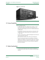
The amplifier front and back are shown below (see Figure 2-1 and
Figure 2-2). Amplifier components are listed alphabetically and described
below.
DOCNUMBER 9500
Document Issue 1, Revision 7
June 2009
Page 2–1