1
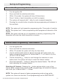
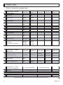
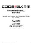
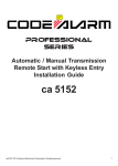
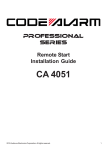
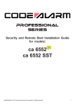
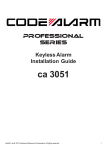
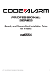
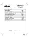
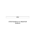
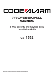
PROFESSIONAL
SERIES
Security and Keyless Entry
Installation Guide
ca 1053
2012 Audiovox Electronics Corporation. All rights reserved.
1
Table of Contents
Before You Begin ...................................................................................... 3
Wire Connection Guide ........................................................................... 4
5 Pin Main Harness ................................................................................... 5
6 Pin Input / Output Harness .................................................................... 6
2 Pin Door Lock Output Harness ............................................................. 8
Additional Ports ...................................................................................... 12
LED Port ................................................................................................... 12
Programming Port .................................................................................... 12
On-Board Shock Sensor ........................................................................ 12
Set Up & Programming .......................................................................... 13
Transmitter Programming ........................................................................ 13
Manual Feature Programming ................................................................. 13
Programming Feature Banks .................................................................. 14
Chirp Delete - User Accessible .............................................................. 15
Dome Light Delay / Theater Dimming ..................................................... 15
Feature Descriptions ............................................................................. 16
Transmitter Button Functions ............................................................. 18
Security Trigger Zones ......................................................................... 18
System Layout ......................................................................................... 19
2
ca1053 rev A.
BEFORE YOU BEGIN
PROFESSIONAL INSTALLATION
STRONGLY RECOMMENDED
Installation Precautions:
Roll down window to avoid locking keys in vehicle
during installation
Avoid mounting components or routing wires near
hot surfaces
Avoid mounting components or routing wires near
moving parts
Tape or loom wires under hood for protection and
appearance
Use grommets when routing wires through metal
surfaces
Use a Digital Multi Meter for testing and verifying
circuits. DO NOT USE A TEST LIGHT, OR
"COMPUTER SAFE PROBE" as these can set off air
bags or damage vehicle computers.
Technical Support (800) 421-3209
or go to
http://techservices.codesystems.com
2012 Audiovox Electronics Corporation. All rights reserved.
3
5 Pin Main Harness
6 Pin Input / Output Harness
2 Pin Door Lock Output Harness
4
ca1053 rev A.
5 Pin Main Harness
1
WHITE/RED
PARKING LIGHT INPUT
2
WHITE
PARKING LIGHT OUTPUT
Locate the parking light output wire at the vehicle’s light switch.
Verification: This wire registers positive voltage when the parking lights
are turned on.
Positive switching Parking Lights:
Connect the WHITE/RED wire to a 15 Amp max fused battery source.
Connect the WHITE wire to the parking light output wire.
Negative switching Parking Lights:
Connect the WHITE/RED wire to a good chassis ground.
Connect the WHITE wire to the parking light output wire.
3
BLACK
GROUND
Connect the BLACK wire to a solid chassis ground point using a ring terminal and
self tapping screw (not supplied). Scrape away paint from the grounding point to
ensure a good connection. The recommended grounding point is a metal surface
in the driver’s side kick panel area.
NOTE: Do not ground the BLACK wire with any other vehicle components.
4
BROWN
SIREN / HORN OUTPUT
This output is available to be used as a constant ( + ) siren output OR a pulsed
( - ) horn output and is selectable by changing the jumper position on the main
module. Refer to the system layout on page 18 for location.
SIREN:
Connect the BLACK siren wire to a chassis ground using a ring terminal and self
tapping screw (not supplied).
Route the BROWN siren output wire from the control module through the firewall
and connect to the RED wire on the siren.
NOTE: Be sure to loom the siren wires, and seal the grommet.
2012 Audiovox Electronics Corporation. All rights reserved.
5
HORN:
Locate the vehicle’s horn wire.
Verification: This wire will register at positive voltage and register
ground when the horn switch is pressed.
Connect the BROWN wire to the vehicle’s horn wire. This is a low current output,
300mA.
5
RED
BATTERY 12V ( + )
Locate 1 of the vehicle’s constant 12 Volt battery wires at the ignition switch.
Verification: This wire will register ( + ) voltage in all positions of the
ignition switch.
Connect the RED wire to the constant 12 Volt battery wire.
NOTE: Remove all fuses until all connections are made.
6 Pin Input / Output Harness
1
PURPLE
DOOR TRIGGER INPUT ( + )
Locate the vehicle’s dome light or door pin switch wire.
Verification: This wire will register positive voltage (POS) when the door is
opened and the interior light is on. This wire will
register ground or "0" Volts when the door is closed and the interior light is
off.
Connect the PURPLE wire to the vehicle’s positive door input wire(s).
NOTE: Certain vehicles may require multiple connections. Refer to vehicle
application guide
2
BLUE
TRUNK PIN INPUT ( - )
Locate the vehicle’s trunk pin switch wire and connect to the BLUE wire.
Verification: This wire when connected will register ground when the
vehicle's trunk is opened.
Connect the BLUE wire to the trunk pin.
6
ca1053 rev A.
3
GREEN
DOOR TRIGGER INPUT ( - )
Locate the vehicle’s dome light or door pin switch wire.
Verification: This wire will register ground (NEG) when the door is opened
and the interior light is on. This wire will register positive voltage when the
door is closed and the interior light is off.
Connect the GREEN wire to the vehicle’s negative door input wire(s).
NOTE: Certain vehicles may require multiple connections. Refer to vehicle
application guide
4
YELLOW
IGNITION INPUT ( + )
Locate the vehicle’s ignition wire at the ignition switch.
Verification: This wire registers voltage when the key is turned to the ON (or
RUN) position. The voltage does not drop out when the key is turned to the
START (or CRANK) position.
Connect the YELLOW wire to the vehicle’s Ignition wire.
5
ORANGE
GROUND WHEN ARMED OUTPUT ( - )
This wire will have a continuous ( - ) 500mA output when the system is Armed. This
wire is typically used for controlling window modules or additional sensors.
6
RED/WHITE
TRUNK RELEASE OUTPUT ( - )
Locate the vehicle’s trunk release wire at the trunk release switch.
Verification: This wire will register either positive voltage or ground when
the trunk release is activated.
This is a low current output, 200mA.
2012 Audiovox Electronics Corporation. All rights reserved.
7
2 Pin Lock Output Harness
1
BLUE
UNLOCK ( - )
2
GREEN
LOCK ( - )
The door lock / unlock outputs are designed to control several different types of
systems which may require additional parts. Please review the wire and location
chart to see which type of door lock system is in your vehicle. The most common
types are shown in the following diagrams.
Negative Switching Locks
All Door Lock and Unlock: Locate the lock / unlock wire at the vehicle’s lock /
unlock switch.
Verification: These wires will register ground when the Lock and Unlock
switches are activated.
Connect the GREEN and BLUE wires shown in the diagram below.
Negative Locks:
GREEN (-) Lock Output
Lock
Vehicle Door Lock
Control Relays
Unlock
BLUE (-) Unlock Output
8
ca1053 rev A.
Positive Switching Locks
All Door Lock and Unlock: Locate the lock / unlock wire at the vehicle’s lock /
unlock switch.
Verification: These wires will register positive voltage when the Lock and
Unlock switches are activated.
Connect the GREEN and BLUE wires shown in the diagram below.
Positive Locks:
Fused +12 Volt
Battery Souce
87
87a
86
85
GREEN (-) Lock Output
30
Lock
Fused +12 Volt
Battery Souce
Vehicle Door Lock
Control Relays
87
Unlock
87a
86
85
BLUE (-) Unlock Output
30
Reverse Polarity Locks (5-Wire Door locks)
All Door Lock and Unlock: Locate the lock / unlock wire at the vehicle’s lock /
unlock switch.
Verification: These wires will rest at ground and register positive
voltage when the Lock and Unlock switches are activated.
Connect the GREEN and BLUE or BLUE/GREEN wires shown in the diagram
below using (2) SPDT relays (not supplied).
Reverse Polarity Locks:
Fused +12 Volt
Battery Souce
87
87a
86
85
GREEN (-) Lock Output
30
Lock
X
To Door Lock Motor
Cut
Unlock
Fused +12 Volt
Battery Souce
87
87a
86
85
BLUE (-) Unlock Output
30
X
To Door Lock Motor
Cut
2012 Audiovox Electronics Corporation. All rights reserved.
9
Negative Multiplexed Locks
All Door Lock and Unlock: Locate the lock / unlock wire at the vehicle’s lock /
unlock switch.
Verification: This wire will show variable ground when the switch is activated.
Please consult the wire and location chart for specific resistor values for
your vehicle.
Connect the GREEN and BLUE or BLUE/GREEN wires shown in the diagram
below using (2) SPDT relays (not supplied).
Multiplex Locks:
Ground
87
87
87a
GREEN (-) Lock Output
86
85
87a
Fused +12 Volt
Battery Source
86
85
BLUE (-) Unlock Output
30
30
Resistor
Lock
Vehicle Door Lock
Control Relays
Unlock
Positive Multiplexed Locks
All Door Lock and Unlock: Locate the lock / unlock wire at the vehicle’s lock /
unlock switch.
Verification: This wire will show variable positive voltage when the switch is
activated. Please consult the wire and location chart for specific resistor
values for your vehicle.
Connect the GREEN and BLUE or BLUE/GREEN wires shown in the diagram
below using (2) SPDT relays (not supplied).
Multiplex Locks:
87
87
87a
GREEN (-) Lock Output
86
85
Fused +12 Volt
Battery Source
Lock
87a
86
85
BLUE (-) Unlock Output
30
30
Resistor
Vehicle Door Lock
Control Relays
Unlock
10
ca1053 rev A.
Adding Aftermarket Actuators
After installing aftermarket actuators, (not supplied). Connect the GREEN and
BLUE wires shown in the diagram below using (2) SPDT relays (not supplied).
Fused +12 Volt
Battery Source
87
Door Lock
Actuator
87a
GREEN (-) Lock Output
85
86
30
Chassis
Ground
M
Fused +12 Volt
Battery Source
87
87a
BLUE (-) Unlock Output
85
86
30
Chassis
Ground
2012 Audiovox Electronics Corporation. All rights reserved.
11
Additional Ports
LED Port
The LED included in the kit will serve as a visual indicator of the alarm’s status. It
should be installed in the dash, located where it can be easily seen from outside
the vehicle, yet not be distracting to the driver. Once a location has been
selected, check behind the panel for wire routing access, and to confirm the drill
will not damage any existing components as it passes through the panel. Drill a
1/4" hole, and pass the red and blue wires from the LED through the hole, from
the front of the panel. Firmly press the body of LED into the hole until fully seated.
Programming / Valet Button Port
Select a mounting location that is within reach of the ignition switch, as this
switch in combination with the ignition switch, will be used to program the certain
features of the system. It is suggested that the switch be mounted to the lower
dash panel in the driver’s area within reach of the driver.
On-Board Shock Sensor
Select a solid mounting surface for the alarm module inside the passenger
compartment (behind the dash), and mount the sensor using cable ties. Refer to
feature programming for on-board shock sensor adjustment.
Data Bus Interface Port
This 4 pin port is used for Flashlogic Door Lock and Transponder Databus
Interfaces to communicate with the vehicle's Databus. When using the DBI port to
control the Flashlogic Door Lock and Transponder Interface modules the
following options may be available. Please refer to the D2D (Data to Data)
function list available per vehicle on the tech service web site.
Door Trigger
Trunk/Hatch Open
Door Lock Control
Dome Light Supervision
Factory Alarm Arm / Disarm
Manual Arm / Disarm Inputs (factory keyless controls system)
12
ca1053 rev A.
Set Up & Programming
Transmitter Programming - Feature Bank 1
1.
Turn the ignition ON.
2.
Press and hold the valet/override button.
3.
Within 10 seconds the system will chirp (3) three times.
4.
Press 1 button of each transmitter you wish to program.
5.
The system will respond with 1 chirp for each accepted transmitter.
6.
Pressing the override button at anytime during programming will advance to
the next bank.
NOTE: The system will exit transmitter programming after 15 seconds of inactivity.
NOTE: This system has 1 button programming which programs all channels of the
system.
NOTE: The system will hold up to 4 transmitters in memory, programming a 5th
transmitter will erase the oldest transmitter in memory.
Manual Feature Programming - Feature Bank 2 - 4
1.
Turn the ignition ON.
2.
Press and hold the valet/override button.
3.
Within 10 seconds the system will chirp (3) three times.
4.
Use the valet/override button to advance through each option bank. For
feature programming advance to Feature Bank 2, 3, or 4 which is (4) four,
(5) five or (6) six chirps.
5.
Use the transmitter
button to scroll through the selections in each
feature bank, the system will chirp to match the feature number.
6.
Press the transmitter button to change the desired feature. The LED will
flash indicating the changed feature.
Defaulting All Features: Pressing the
button anytime while in any of the
feature banks (except during shock sensor programming) will default all features
and return you to feature bank 2 - 4 chirps.
NOTE: The system will remain in feature programming mode as long as the
ignition is on, there is no time limit. To exit programming turn the IGNITION OFF.
2012 Audiovox Electronics Corporation. All rights reserved.
13
Feature Bank 1 - 3 Chirps
Transmitter Programming
Refer to transmitter programming.
Feature Bank 2 - 4 Chirps
Security Control
1 LED Flash
2 LED Flash
1
Silent Choice
ON
OFF
2
Passive Locks
Active
Passive
3
Passive Arming
Active
Passive
4
N/A
N/A
5
N/A
N/A
6
N/A
N/A
7
Anti-Hijack Mode
OFF
8
N/A
N/A
9
DBI Port Protocol
DBI Protocol
ADS Protocol
10
Arm/Disarm
Chirp / Parking Light Pattern
Standard:
2 - Arm
1 - Disarm
Inverted:
1 - Arm
2 - Disarm
Feature Bank 3 - 5 Chirps
Output Control
1 LED Flash
1
Extended Lock Pulse
1 Second
2
Factory Disarm
N/A
3
Ignition Controlled Locks
OFF
Feature Bank 4 - 6 Chirps
Shock Sensor Adjustment
1
Full Trigger
3 LED Flash
4 LED Flash
5 LED Flash
2 LED Flash
3 LED Flash
4 LED Flash
5 LED Flash
3.5 Seconds
1 Second
Lock, Double
Pulse Unlock
30 Second
Lock, Double
Pulse Unlock
Double Pulse
Lock, 1
Second Unlock
Lock and
Unlock
Lock Only
Unlock Only
ON
Increase Sensitivity
Decrease Sensitivity
Press & Release Lock
Press & Release Unlock
Press Lock + Unlock for 2 seconds to lock in the change and move to next setting.
2
Lite Touch
Press & Release Lock
Press & Release Unlock
Press and release Lock + Unlock to lock in the change and exit programming.
14
ca1053 rev A.
Feature Bank 4 - Shock Sensor Adjustment
1.
Enter Feature Bank 4
to select full trigger.
2.
Press and release
3.
Use or
to adjust the settings. The system will give short chirps upon
each press.
4.
Press + for 2 seconds to lock in the change and advance to the lite
touch setting, the system will give 2 long chirps to confirm.
5.
Use
6.
Press and release +
to lock in the change, the system will exit
programming and give 1 long chirp to confirm. This step must be
completed to properly program the shock senor.
or
to adjust the settings.
Chirp Delete - User Accessible
System ARM/DISARM chirps can be toggled ON or OFF without entering the
programming feature banks.
1.
Turn the ignition ON then OFF.
2.
Press and release the valet/programming button 3 times. The system
will respond with 1 chirp for ON or 2 chirps for OFF.
Dome Light Delay / Theater Dimming
The system can be programed to delay arming after the lock button is pressed (60
second max) for vehicles with a dome light delay or theater dimming feature. Once
programed the system will ‘learn’ the timing of the dome light delay and add 2
seconds before arming.
1.
Close all doors with ignition off.
2.
Using the transmitter press LOCK, UNLOCK, LOCK ,UNLOCK, LOCK ,
UNLOCK, LOCK. The LED will light solid to indicate the system has
entered DOME DELAY LEARN MODE.
3.
Immediately OPEN then CLOSE the door WITHOUT disarming the
system. The system will then monitor the door trigger wire. Once the
dome light turns off, the system will then add 2 seconds and then exit
the learning mode.
4.
The LED will begin to flash indicating the system has exited the
learning mode and is now armed.
2012 Audiovox Electronics Corporation. All rights reserved.
15
Feature Descriptions
Feature Bank 2 - Security
1 - Silent Choice: Controls the normal arm/disarm chirps of the security system.
ON - Silent arming/disarming upon first press of lock/unlock, pressing lock/
unlock a second time will activate the arm/disarm chirps respectively. The
system will only sound the arm/disarm chirps upon a second press of the
lock/unlock buttons.
OFF - normal arm/disarm chirps upon the first press of lock/unlock.
2 - Passive Locks: Determines manual or automatic locking of the vehicle’s
doors.
Active - Requires use of the transmitter to lock the vehicle’s doors.
Passive - Automatically locks the vehicle’s doors 1 minute after the last door
is closed
3 - Passive Arming: Determines manual or automatic locking of the vehicle’s
doors.
Active - Requires use of the transmitter to arm the security system.
Passive - Automatically arms the security system 1 minute after the last
door is closed
4 - Not available on this model.
5 - Not available on this model.
6 - Not available on this model.
7 - Anti-Hijack Mode: Controls the Car Jack mode - ON / OFF.
OFF - Standard security system operation.
ON - Enables Car Jack mode functionality as described in the owners
manual
8 - Not available on this model.
16
ca1053 rev A.
9 - DBI Port Protocol: Determines the protocol type in which the DBI port uses to
interface with external modules.
DBI Protocol
ADS Protocol
10 - Arm/Disarm Chirp / Parking Light Pattern: Determines the number of
chirps and parking light flashes when the system is armed/disarmed.
Standard - 2 chirps/light flashes with arm, 1 chirp/light flash with disarm.
Inverted - 1 chirp/light flash with arm, 2 chirps/light flashes with disarm.
Feature Bank 3 - Output Control
1 - Extended Lock Pulse: Controls the timing of the BLUE and GREEN lock
output wires.
1 Second - Single 1 second lock pulse, single 1 second unlock pulse.
3.5 Seconds - Single 3.5 second lock pulse, single 3.5 second unlock pulse.
1 Second Lock, Double Pulse Unlock - Single 1 second lock pulse, double 1
second unlock pulse.
30 Second Lock, Double Pulse Unlock - Single 30 second lock pulse, double
1 second unlock pulse.
Double Pulse Lock, 1 Second Unlock - Double 1 second lock pulse, single 1
second unlock pulse.
2 - Not available on this model.
3 - Ignition Controlled Locks: Control of door locks when the ignition is cycled
ON or OFF.
OFF - Door locks not activated by ignition.
Lock and Unlock - Doors lock when ignition is turned on and unlock when
ignition is turned off.
Lock Only - Doors lock when ignition is turned on.
Unlock Only - Doors unlock when ignition is turned off.
2012 Audiovox Electronics Corporation. All rights reserved.
17
Transmitter Button Functions
Lock
Lock
Unlock
Car Find /
Panic
Trunk
Operation Method
Press and Release
X
Unlock
Press and Release
X
Trunk
X
Push and Hold (3 Sec)
Car Finder
X
Press and Release
Panic
X
Push and Hold (3 Sec)
X
Press and Release Lock then Press
Lock + Car Find (within 5 Sec)
Shock Bypass
X
Passive Arming
Bypass
Arm with
Hidden Alarm
Function
X
X
Press 2 Times (within 5 Sec)
X
Press Trunk then Lock (within 5
Sec)
Security Trigger Zones
If the security system has been triggered the LED will flash one of the patterns
below indicating the zone.
LED FLASHES TRIGGER ZONE
18
2 Flashes
Hood / Trunk Input
3 Flashes
Door Input
4 Flashes
Shock Sensor
5 Flashes
Ignition Input
ca1053 rev A.
STARTER INTERUPT RELAY
86
87a
87
30
85
ORANGE
YELLOW
WHITE
RED
OPEN
2012 Audiovox Electronics Corporation. All rights reserved.
86 - ARMED OUTPUT ( - )
85 - IGNITION ( + )
87A - STARTER OUTPUT - MOTOR SIDE
30 - STARTER INPUT - KEY SIDE
87 - OPEN
19
(-)
(+)
CA 1053
DOOR TRIGGER INPUT ( + )
TRUNK PIN INPUT ( - )
DOOR TRIGGER INPUT ( - )
IGNITION INPUT ( + )
ARMED OUTPUT ( - )
TRUNK RELEASE OUTPUT ( - )
UNLOCK OUTPUT ( - )
LOCK OUTPUT ( - )
PARKING LIGHT INPUT
PARKING LIGHT OUTPUT
GROUND
SIREN OUTPUT
BATTERY 12V ( + )
DBI PORT
PROGRAMMING / VALET PORT
PURPLE
BLUE
GREEN
YELLOW
ORANGE
RED/WHITE
LED PORT
BLUE
GREEN
WHITE/RED
WHITE
BLACK
BROWN
RED
SIREN / HORN OUTPUT POLARITY JUMPER
Audiovox Electronics Corporation.
Customer Service 1-800-421-3209
WWW.CODE-ALARM.COM
FCC COMPLIANCE
This device complies with Part 15 of the FCC rules and with RSS-210 of
Industry Canada. Operation is subject to the following two conditions:
1. This device may not cause harmful interference, and
2. This device must accept any interference received, including any interference
that may cause undesired operation.
Warning!
Changes or modifications not expressly approved by the party responsible for
compliance could void the user’s authority to operate the equipment.
20
ca1053 rev A.