1
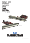
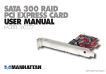
eSATA II 1+1 PCIe RAID Card RC213
User Manual
eSATAII 1+1 PCIe RAID Card RC213
User Manual
Important Message for User before Installing RC-213:
Before controller card installation, we recommend the users to study this manual and the PDF file of SATARaid5
Manual at enclosed CD folder\SATA PCIe_Raid5_2Port\SiI3132\Windows\Gui ( or\Raid5 SATA2_4Port\SiI3124\
Windows\Gui ) first. This Raid manual has more information on Raid architecture, Raid features, Raid
installation, Raid setting and Management software for Raid5 GUI (Graphical User Interface).
1. Windows Device Manager can NOT recognize the hard drives that without correct RAID setting before.
2. The working data on your existing HDD may NOT work when you migrate it to RAID Host Card.
3. After driver installation, if you like, you can install SATARaid5 GUI for Raid management. Before
SATARaid5 GUI installation, you must remove all the existing SATARaid GUI (or Java SATARaid GUI) to
ensure your new SATARaid5 GUI can work properly.
i.e. : (\Start\Control Panel\Add or Remove Programs\Select all SATARaid \Remove)
4. Raid sets can be created and managed by either the BIOS utility setting or the SATARAID5 GUI setting under
Windows.
5. For RAID creating, BIOS utility allow the random creating but GUI just supports the building by sequential SATA
Port1, Port2, Port3 ……..
6. If you use the used HDD to Raid5 card, you must perform the "Delete Raid Set" on BIOS setting, since your used
HDD has some system data and Raid5 card may confuse on that and no recognition.
7. RAID5 setting may cost hours for component ready and function available, please be patient for that. Especially if
Raid5 setting by BIOS, please Click “Task Manager” to make sure Raid setting is completed. It shall be “Green” color
on the selected components.
8. The “Rebuilding” function on Raid 1 or Raid 10 may spend long hours for component ready and function available,
please be patient for that.
9. Raid 0 and Raid1 need at least 2 drives, and Raid10 need 4 drives and Raid5 need 3 drives at least. If 1 hard drive only,
make sure to have “Concatenate” or “Contiguous” setting.
11. The setting of Raid 0, 1, 10, 5 and JBOD will appear on screen accordingly and automatically when Port
Multiplier and multiple Drives be connected
12. Backup all your data in HD before setting any RAID. Setting RAID 0/0+1/5 will destroy all original data of your HD)
13. New HD connecting to RC-213 must process “initial (F-disk)” and “format” before using. Otherwise, PC might find
nothing in the system.
14. If you want to boot from correct HD connecting to either motherboard or RC-213, please change correct HD
source from CMOS “booting sequence”.
15. Although SATA HD is a “hot swap” design, it is strongly recommended that all users turn off the power before you
add any HD to PC.
16. If you want to use RC-213 without any RAID function, please do not enter RAID BIOS and change the RAID setting.
RAID function will only be activate after you enter RAID BIOS and set a RAID set correctly. Driver installation is the
same for a RAID card whether you want to use a RAID function or not. Never install a un-RAID version driver to a
RAID card even you want to use a RAID card without RAID function.
2
eSATAII 1+1 PCIe RAID Card RC213
User Manual
1. Introduction
This Low Profile PCI-Express Host Adapter is a controller board to support Low profile PCI and regular size PCI both
in one card. The card can upgrade your desktop computer to have 2 ports Serial ATA II transfer rate of 3 Gb/s (300
MB/s).
The board can be used to upgrade your desktop computer to have 2Ports Serial ATA Channels and support RAID 5,
RAID 0+1, RAID 0, RAID 1 and JBOD features. It accepts host commands through the PCI Express bus, processes
them and transfers data between the host and Serial ATA devices. The board should be connected to SATA target
device and will take the data, serialize it and output it for transmission over the SATA interface. The board can control
four independent Serial ATA channels. Each channel has its own Serial ATA bus and will support one Serial ATA device.
The board supports Serial ATA Generation 1 & Generation 2 transfer rate of 1.5 Gbps / 3Gbps. It comes completely
with drivers for Windows 2000, Windows XP, Windows 2003.
RAID, Redundant Array of Independent Disks, greatly enhances two main areas of data storage: performance and
data integrity. By using RAID 0, also known as Striping, performance of sustained data transfer rates is greatly
enhanced by simultaneously writing data to 2, 3 or 4 drives. The second benefit of RAID is data redundancy. RAID 1,
Mirroring, writes identical data on two drives or sets of drives, thus protecting the data from a disk failure. If, for any
reason, one drive were to fail, your data is secure and available from the mirrored second drive.
1.1. Features
1. External SATA II (eSATA) Connector.
2. 48 bits LBA can Break Capacity-Limit to Support HDD larger than 137GB.
3. Supports 1-lane 2.5Gbps PCI Express.
4. Hot-plug capability.
5. Supports SATA II transfer rate of 3.0Gbps.
6. Fully compliant with Serial ATA 1.0 specifications.
7. Supports two independent Serial ATA channels.
8. Independent Link, Transport, and data FIFO.
9. Independent command fetch, scatter/gather, and command execution.
10. Supports Legacy Command Queuing (LCQ).
11. Supports Native Command Queuing (NCQ).
12. Supports Non-zero offsets NCQ.
13. Supports Out of order data delivery NCQ.
14. Supports FIS-based switching with Port Multipliers.
15. 31 Commands and Scatter/Gather Tables per Port.
16. Two Pin headers on board for LED connection.
17. Completely with drivers for Windows 2000, Windows XP, Windows Server 2003 and Windows VISTA.
18. Provides RAID 0 (Stripping) to greatly increase the performance of data transfer by simultaneously writing data
to 2 drives.
19. Provides RAID 1 (Mirroring) to protect the data from a disk failure by writing identical data on 2 drives.
3
eSATAII 1+1 PCIe RAID Card RC213
User Manual
20. RAID 0+1 (Mirrored-Stripping) combine both Striping and Mirroring technologies to provide both the performance
enhancements that come from Striping and the data availability and integrity that comes from Mirroring.
1.2. Package Contents
1. RC-213 RAID5 SATA II – 3Gbps 2Ports PCI Express Host Adapter
2. This Users Manual
3. Driver CD
4. Low profile bracket
2. What Is RAID
RAID - Redundant Array of Independent Disks
RAID technology manages multiple disk drives to enhance I/O performance and provide redundancy in order to
withstand the failure of any individual member, without loss of data.
Disk Striping (RAID 0)
Striping is a performance-oriented, non-redundant data mapping technique. While Striping is discussed as a
RAID Set type, it is actually does not provide fault tolerance. With modern SATA bus mastering technology,
multiple I/O operations can be done in parallel, enhancing performance. Striping arrays use multiple disks to form a
larger virtual disk.
Disk Mirroring (RAID 1)
Disk mirroring creates an identical twin for a selected disk by having the data simultaneously written to two disks.
This redundancy provides instantaneous protection from a single disk failure. If a read failure occurs on one drive,
the system reads the data from the other drive.
Mirrored-Striping (RAID 0+1 also known as RAID 10)
(If you want to set RAID 5 with RC-213, you need to buy a SATA multibay system to work with RC-213)
A Mirrored-Striping Set does just what it says, combining both Striping and Mirroring technologies to provide
both the performance enhancements that come from Striping and the data availability and integrity that comes from
Mirroring. When data is written to a Mirrored-Striped Set, instead of creating just one virtual disk as Striping would do, a
second, Mirrored virtual disk is created as well.
Parity RAID (RAID 5)
(If you want to set RAID 5 with RC-213, you need to buy a SATA multibay system to work with RC-213)
Parity or RAID 5 adds fault tolerance to Disk Striping by including parity information with the data. Parity RAID
dedicates the equivalent of one disk for storing parity stripes. The data and parity information is arranged on the
disk array so that parity is written to different disks. There are at least 3 members to a Parity RAID set. The following
example illustrates how the parity is rotated from disk to disk.
Parity RAID uses less capacity for protection and is the preferred method to reduce the cost per megabyte for larger
4
eSATAII 1+1 PCIe RAID Card RC213
User Manual
installations. Mirroring requires 100% increase in capacity to protect the data whereas the above example only
requires a 50% increase. The required capacity decreases as the number of disks in the group increases.
Just Bunch of Disks (JBOD, Contiguous)
The JBOD here (also known as Contiguous) means a logical drive that can either be an entire disk drive or a segment of
a single disk drive. For this card, JBOD function only supports one disk. JBOD here is a Contiguous configuration option
when “Create RAID Group” in SATARAID5 Manager Utility.
3. Installation Procedures
Quick guide: There are three installation situations as below 1~3. Please read carefully and choose correct
installation for your need.
1. If you want to add RC-213 to an existing OS (In this case, PC is booting up by an existing HD connecting to
motherboard. This situation will allow you adding new RAID or un-RAID additional storage HD to your original system),
install RC-213 into a PCI slot. Boot up the system and enter the OS. Install RC-213 with driver disk coming in the box.
After RC-213 is installed correctly, you can add HD and set the RAID by RAID BIOS.
Please check Section 4 “BIOS Setting ( RAID Setting )” for RAID setting.
2. If you want to add RC-213 to a new PC without any OS, you need to boot the OS from HD connecting to RC-213
instead of motherboard. In this case, you can construct a new RAID 0/1/0+1/5 set as main booting system.
a. Put the driver (the driver version must fit the OS you want to install to the HD) into a floppy disk and keep the
floppy disk in the floppy drive.
b. Plug the HD to RC-213. Turn on PC, press CTRL+S or F4 to enter RAID BIOS. Complete the RAID set according to
which RAID you want to use.
Please check Section 4 “BIOS Setting ( RAID Setting )” for RAID setting.
c. After you complete RAID setting, save and left the setting.
d. Inset Windows installation disk and start the windows installation.
e. Press F6 at the beginning as the blue screen scanning.
This will let PC boot from an additional HD controller instead of motherboard HD.
5
eSATAII 1+1 PCIe RAID Card RC213
User Manual
f. Keep the floppy in floppy drive and follow the installation.
Press “S” when the screen shows as the following picture.
6
eSATAII 1+1 PCIe RAID Card RC213
User Manual
g. Choose the correct OS for your future system.
h. Keep the floppy disk in floppy drive during the installation. PC will notice you as below if you take them off from
the drive.
7
eSATAII 1+1 PCIe RAID Card RC213
User Manual
i.The installation of RC-213 by floppy drive will be completed right now. The system will detect the HD which plugs on
the card right now.
After you install RC-213 successfully by floppy disk, installation will lead you back to Windows Setup. System will
ask you if you want to specify additional SCSI adapter for use in Windows. Please press “enter” to left the setting.
j. Once the system can find the HD connecting to RC-213, you can follow the normal steps to complete the Windows
installation.
3. If you want to create a mirror set by a HD with existing OS and a fresh HD, the data on existing HD will copy to
another fresh HD and boot as RAID 1 HD set. In this case, you will boot your computer from a Mirror HD set
connecting to RC213 instead of motherboard. Please follow the following instructions.
a. Install RC-213 into a PCI slot. Boot up the system and enter the OS. Install RC-213 with driver disk coming in
the box.
b.After RC-213 installation complete, turn off PC. Take the original system HD off from motherboard and connect to
RC-213. Take another fresh HD to connect to RC-213 to set a mirror.
c. Turn on PC and enter the RAID BIOS to set a mirror set. Choose “Manual” during the installation and select the
original HD as the data source to complete mirror copy. The copy will take a long time depending on your HD
capability. After data copy complete, save and left RAID BIOS.
Important message:
If you choose the wrong HD source at the step of “manual”, all your data will be lost.
d. Reboot your PC and now you can enter your OS with RAID 1.
8
eSATAII 1+1 PCIe RAID Card RC213
User Manual
Detail guide:
1. Power down the computer system.
2. Insert the Host card into an available bus slot.
3. Power ON.
4. Install Device Driver as section 5.
5. Remove all the existing SATARaid GUI (or Java SATARaid GUI) to ensure your new SATARaid5 GUI can
work properly.
6. Install new SATARaid5 GUI.
7. Power down the computer system again.
8. Connect Hard Drives to SATA Ports.
9. Power ON.
10. If you connect the used HDDs to SATA Ports, Press CTRL+S or F4 and delete Raid setting on every used HDD
when BIOS booting.
11. Use SATARAID5 Manager GUI for RAID configuration setting.
If 1 Disk, please select “Concatenate” or “Contiguous” setting only.
If 2 Disks, don’t select “Parity RAID” or “Mirrored Striped” setting
If 3 Disks, don’t select “Mirrored Striped” setting
12. Click “Task Manager” to make sure Raid setting is completed. It shall be “Green” color or “Blue” color on the
selected components. RAID5 setting may cost hours for component ready and function available, please be
patient for that.
13. Use Device Manager for hard disk initialization, partition and formatting.
4. BIOS Setting ( RAID Setting )
Creating and deleting RAID sets is a function found in the BIOS. During boot up, the RAID setting message will appear
and pause for a few moments to allow the user to choose what to do. This board will act as normal NON-RAID card
when BIOS not configured for RAID. Just proceed to Software Installation section directly. If you use traditional
parallel ATA HDD, make sure your hard drives be set up as master mode before the RAID setting.
4.1. Creating Striped Sets (RAID 0)
1. As the BIOS boots, Press CTRL+S or F4 to enter the raid bios utility.
2. Select Create RAID set. Press Enter.
3. Select RAID 0 then press Enter.
4. Select Number of hard drive. Press Enter.
5. Select RAID size. Press Enter.
6. Press Y to save your settings.
7. Press CTRL+E and then press Y to exit the setup.
8. Continue with conventional Fdisk and Format steps as if you are installing a conventional hard drive.
9. Your RAID configuration is complete. Please proceed to software installation section.
4.2. Creating Mirrored Sets (RAID 1)
1. As the BIOS boots, Press CTRL+S or F4 to enter the raid bios utility.
9
eSATAII 1+1 PCIe RAID Card RC213
User Manual
2. Select Create RAID set. Press Enter.
3. Select RAID 1 then press Enter.
4. Select Auto configuration. Press Enter.
5. Press Y to save your settings.
6. Press CTRL+E and then press Y to exit the setup.
7. Continue with conventional Fdisk and Format steps as if you are installing a conventional hard drive.
8. Your RAID configuration is complete. Please proceed to software installation section.
4.3. Creating a Mirrored-Striped Set (RAID 10)
1. As the BIOS boots, press CTRL+S or F4 to enter the raid bios utility.
2. Select Create RAID set. Press F2.
3. Select RAID 10 then press Enter.
4. Select Auto config. Press Enter.
5. Press Y and then press ESC to exit the setup.
6. Continue with conventional Fdisk and Format steps as if you are installing a conventional hard drive.
7. Your RAID configuration is complete. Please proceed to software installation section.
4.4. Creating Parity RAID (RAID 5)
1. As the BIOS boots, Press CTRL+S or F4 to enter the raid bios utility.
2. Select Create RAID set. Press Enter.
3. Select RAID 5 then press Enter.
4. Select Auto configuration. Press Enter.
5. Press Y to save your settings.
4.5. Creating JBOD Sets
1. As the BIOS boots, Press CTRL+S or F4 to enter the raid bios utility.
2. Select Create RAID set. Press Enter.
3. Select JBOD (Single) then press Enter.
4. Select JBOD Drives. Press Enter.
5. Select RAID size. Press Enter.
6. Press Y to save your settings.
4.6. Creating Spare Drive
1. As the BIOS boots, Press CTRL+S or F4 to enter the raid bios utility.
2. Select Create RAID set. Press Enter.
3. Select Spare Drive then press Enter.
4. Select Spare Drives. Press Enter.
5. Select RAID size. Press Enter.
6. Press Y to save your settings.
10
eSATAII 1+1 PCIe RAID Card RC213
User Manual
4.7. Deleting RAID Sets
1. As the BIOS boots, Press CTRL+S or F4 to enter the raid bios utility.
2. Select Delete RAID set. Press Enter.
3. Answer Y to remove the RAID set. If the RAID set being deleted is a Striped set, then all of the data will be lost. If the set
being deleted is a Mirrored set, then the data will remain intact and accessible on both drives.
4.8. Rebuilding Mirrored Sets (RAID 1)
1. After replacing the failed hard drives boot the BIOS, Press CTRL+S or F4 to enter the raid bios utility.
2. Select Rebuild RAID 1 set. Press Enter.
3. Select Rebuild Hard Drive. Press Enter.
4. Answer Y to rebuild the Mirrored set of hard drive.
4.9. Resolving Conflict
When a RAID set is created, the metadata written to the disk includes drive connection information (Primary and
Secondary). If, after a disk failure, the replacement disk was previously part of a RAID set (or used in another system),
it may have conflicting metadata, specifically in reference to the drive connection information. If so, this will prohibit
the RAID set from being either created or rebuilt, In order for the RAID set to function properly, this old metadata must
be first overwritten with the new metadata. To resolve this, select Resolve Conflicts, and the correct metadata,
including the correct drive connection information, will be written to the replacement disk.
5. Software Installation
5.1. Windows 2000/XP/2003/VISTA Fresh Installation
1. Power off the system. Connect the hard drives to the controller card and insert the controller card into a PCI
Express slot. Power up the system.
2. Put your Windows 2000/XP CD into the CD-ROM/DVD drive, or the 2000/XP boot diskette #1 in the floppy
drive if your system cannot boot from the CD.
3. Press F6 for third party SCSI or driver installation at the beginning of text mode installation. Press 's' when
setup asks if you want to specify an additional device and insert the Driver CD. Press 'Enter' and select 'E:\
SATA PCIe_Raid5_2Port \SiI3132\Windows\Driver'.
4. Press 'Enter' to continue on with text mode setup.
5. Follow the setup instructions to select your choice for partition and file system.
6. After setup examines your disks, it will copy files to Windows 2000 installation folders and restart the system.
The setup program will continue and finish the installation after restart.
7. Waiting until Windows finishes installing devices, regional settings, networking settings, components, and final
set of tasks, reboot the system if it is required.
8. See instructions in section 5.3 to verify controller was installed correctly.
11
eSATAII 1+1 PCIe RAID Card RC213
User Manual
5.2. Adding the controller card to an existing Windows 2000/XP/2003/VISTA Installation
1. Power off the system. Connect the hard drives to the controller card and insert the controller card into a
PCI Express slot. Power up the system.
2. During OS boot up, Windows will display the 'Found New Hardware Wizard'. Click 'Next'.
3. Select 'Search for a suitable driver for my device (Recommended)' and Click 'Next'.
4. Insert the Driver CD in your CD-ROM/DVD drive, check Specify a location, uncheck the other boxes, click Next,
type in E:\ (If your CD-ROM/DVD is E:\). Click Browse.
5. Points specify a location, example E:\ SATA PCIe_Raid5_2Port \ SiI3132 \ Windows \ Driver,
click Open then OK.
6. When the wizard indicates that it found a driver for the device click 'Next'.
7. If the 'Digital Signature Not Found' dialog appears, click 'Yes' to continue installing the driver.
8. The wizard will now copy the required files to the system and start the driver. After starting the driver the wizard
will display a completion dialog, click 'Finish' to exit the wizard.
9. See instructions in section 5.3 to verify controller was installed correctly.
5.3. Verifying controller installation under Windows2000/XP/2003/VISTA
1. Right click on 'My Computer' icon, select 'Properties', left click on 'Hardware' tab and then on
'Device Manager' button.
2. Double click on 'SCSI and RAID Controllers', If there is no yellow '!' or '?' in front of 'Silicon Image
SiI 3132 SoftRaid5 Controller', the driver is started correctly.
3. To view information about the devices attached to the controller, use the SiICfg Utility and click on the device
from the list.
5.4. Update new driver on Windows 2000/XP/2003/VISTA with existing driver
1. Right click on 'My Computer' and select 'Properties'. Under the 'System Properties' section, click on
'Hardware' tab and then on 'Device Manager' click 'SCSI and RAID Controller' and right click 'Silicon Image SiI
3132 SoftRaid5 Controller'.
2. Click 'Driver', 'Update Driver' and select 'Search for a suitable driver for my device [Recommended]'. Insert the
Driver CD. Press 'Enter' and select 'E:\ SATA PCIe_Raid5_2Port \SiI3132\Windows \Driver'. Click 'Next' and complete
the driver installation.
3. System will go through the enumeration process and install the driver. At the end of the process, click 'Yes' to
reboot your system when necessary.
4. See instructions in section 5.3 to verify controller was installed correctly.
Thank you for purchasing a quality Rosewill Product.
Please register your product at : www.rosewill.com for complete warranty information and future support for your product.
12