1
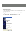
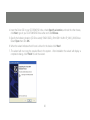
Installation Guide
RAID5 eSATA 1.5Gbps 4 External port PCI Card
GIC704SR5W6
1
PART NO. M0560
Table of Contents
Caution
4
Introduction
5
Features
6
Package Contents
7
What Is RAID?
8
Installation Procedure
11
Software Installation
18
Federal Communications Commission
(FCC) Statement
22
CE Statement
24
Limited Warranty
25
Contact
26
3
Caution
• Before installation of the controller card, we recommend that users study this manual first. This RAID
manual has more information on RAID architecture, RAID features, RAID installation, RAID settings and
Management software for the RAID5 GUI (Graphical User Interface).
• Windows Device Manager cannot recognize hard drives without the correct RAID settings in place.
• The working data on your existing hard drive may NOT work when you migrate it to a RAID Host Card
configuration.
• After driver installation you can install the SATARAID5 GUI for RAID management. Before the
SATA RAID5 GUI installation, you must remove all existing SATARAID GUIs (or Java SATARAID GUI) to
ensure your new SATARAID5 GUI works without issues.
• RAID sets can be created and managed by either the BIOS utility setting or the SATARAID5 GUI setting
under Windows.
• If you’re using a used hard drive with the RAID5 card you must perform the “Delete RAID Set” under
the BIOS settings. The reason this is necessary is because the used hard drive has system data on it
which may cause recognition issues when configuring it for use with the RAID5 card.
• RAID 0 and RAID1 setups require at least 2 drives, with RAID5 requiring 3 drives and RAID10 requiring
4 drives. If only one drive, make sure to have “Concatenate” or “Contiguous” setting.
4
Introduction
The board offers the ability to upgrade your desktop computer to RAID 5, RAID 0+1, RAID 0, or RAID
1 as well as JBOD. The board can control four independent Serial ATA channels. Each channel has its
own Serial ATA bus and will support one Serial ATA device. The board supports Serial ATA Generation 1
transfer rates of 1.5 Gb/s (150 MB/s).
5
Features
PCI Interface
• Compliant with PCI Specifications, Revision 2.2.
• Integrated PCI DMA engines.
• 32 bit, 33/66MHz fully compliant PCI host interface.
High Speed Serial ATA Interface
• Four high speed Serial ATA interface ports, each supporting 1st generation Serial ATA data rates
(1.5Gb/s).
• RAID 5 (Distributed Parity RAID) has Highest Read data transaction rate and Good aggregate transfer rate.
• Provides RAID 0 (Stripping) to greatly increase the performance of data transfer by simultaneously writing
data to 2 drives.
• Provides RAID 1 (Mirroring) to protect the data from a disk failure by writing identical data on 2 drives.
• RAID 0+1 (Mirrored-Stripping) combine both Striping and Mirroring technologies to provide both the
performance enhancements that come from Striping and the data availability and integrity that comes
from Mirroring.
• JBOD is a virtual disk that combines all disk drives as one entire disk drive.
• Fully compliant with Serial ATA 1.0 specifications.
• Supports Spread Spectrum in receiver.
• Independent 256-byte FIFOs (32 bit * 64 deep) per Serial ATA channel for host reads and writes.
6
Package Contents
• RAID5 SATA-150 4Ports PCI Host Adapter
• Quick Start Guide
• Driver CD
7
What Is RAID?
RAID - Redundant Array of Independent Disks
RAID technology manages multiple disk drives to enhance I/O performance and provide redundancy in
order to withstand the failure of any individual drive, without loss of data.
Disk Striping (RAID 0)
Striping is a performance-oriented, non-redundant data mapping technique. While Striping is discussed
as a RAID Set type, it actually does not provide fault tolerance. With modern SATA bus technology,
multiple I/O operations can be done in parallel, enhancing performance. Striping arrays use multiple disks
to form a larger virtual disk.
Disk Mirroring (RAID 1)
Disk mirroring creates an identical twin for a selected disk by having the data simultaneously written to
two disks. This redundancy provides instantaneous protection from a single disk failure. If a read failure
occurs on one drive, the system simply reads the data from the other drive.
8
Mirrored-Striping (RAID 0+1 also known as RAID 10)
A Mirrored-Striping Set does just what it says, combining both Striping and Mirroring technologies to provide both the performance enhancements that come from Striping and the data availability and integrity
that comes from Mirroring. When data is written to a Mirrored-Striped Set, instead of creating just one
virtual disk as Striping would do, a second Mirrored virtual disk is created as well.
Parity RAID (RAID 5)
Parity or RAID 5 adds fault tolerance to Disk Striping by including parity information with the data. Parity
RAID dedicates the equivalent of one disk for storing parity stripes. The data and parity information is
arranged on the disk array so that parity references are written to different disks. There are at least 3
members to a Parity RAID set.
Parity RAID uses less capacity for protection and is the preferred method to reduce the cost per megabyte
for larger installations. Mirroring requires 100% increase in capacity to protect the data whereas the above
example only requires a 50% increase. The required capacity decreases as the number of disks in the
group increases.
9
Just a Bunch of Disks (JBOD/Contiguous)
JBOD (also known as Contiguous) means a logical drive that can either be an entire disk drive or a segment
of a single disk drive. For this card, the JBOD function only supports one disk. JBOD here is a Contiguous
configuration option when using the “Create RAID Group” within the SATARAID5 Manager Utility.
10
Installation Procedure
1. Power down the computer system.
2. Insert the Host card into an available bus slot.
3. Power on the computer system.
4. Install drivers for the device.
5. Remove all existing SATARAID GUIs (or Java SATARAID GUIs) to ensure your new SATARAID5 GUI
installs and functions properly.
6. Install the SATARAID5 GUI.
7. Power down the computer system once again.
8. Connect Hard Drives to the proper SATA Ports.
9. Power on the computer system once again.
10. If you connect any used HDDs to the SATA Ports, Press CTRL+S or F4 and delete any RAID settings
that may be on the drives when using the BIOS boot method.
11
11. Use the SATARAID5 Manager GUI to configure your RAID settings.
If using 1 Disk, please select “Concatenate” or “Contiguous” settings only.
If using 2 Disks, do NOT select “Parity RAID” or “Mirrored Stripe” settings.
If using 3 Disks, do NOT select the “Mirrored Stripe” setting.
12. Open “Task Manager” to make sure the RAID setup is completed. RAID5 can take hours to complete,
please be aware of these time requirements.
13. Use Device Manager for hard disk initialization, partition and formatting within Windows.
12
BIOS (RAID Settings)
Creating and deleting RAID sets is a function found in the BIOS. During boot up, the RAID setting message
will appear and pause for a few moments to allow the user access to its settings. The board will act as a
normal NON-RAID card when the BIOS does not have it configured for RAID. If you’re using traditional parallel
ATA HDDs, make sure your hard drives are set to master mode before accessing the RAID settings.
Creating Striped Sets (RAID 0)
1. As the BIOS boots, Press CTRL+S or F4 to enter the RAID bios utility.
2. Select Create RAID set. Press Enter.
3. Select RAID 0 then press Enter.
4. Select the Number of hard drives. Press Enter.
4. Select RAID size. Press Enter.
5. Press Y to save your settings.
6. Press CTRL+E and then press Y to exit the setup.
7. Continue with conventional Fdisk and Format steps to prepare the hard drives.
8. Your RAID hardware configuration is complete. Proceed to software installation section.
13
Creating Mirrored Sets (RAID 1)
1. As the BIOS boots, Press CTRL+S or F4 to enter the RAID bios utility.
2. Select Create RAID set. Press Enter.
3. Select RAID 1 then press Enter.
4. Select Auto configuration. Press Enter.
5. Press Y to save your settings.
6. Press CTRL+E and then press Y to exit the setup.
7. Continue with conventional Fdisk and Format steps to prepare the hard drives.
8. Your RAID hardware configuration is complete. Proceed to software installation section.
14
Creating a Mirrored-Striped Set (RAID 10)
1. As the BIOS boots, press CTRL+S or F4 to enter the RAID bios utility.
2. Select Create RAID set. Press F2.
3. Select RAID 10 then press Enter.
4. Select Auto configuration. Press Enter.
5. Press Y and then press ESC to exit the setup.
7. Continue with conventional Fdisk and Format steps to prepare the hard drives.
8. Your RAID hardware configuration is complete. Proceed to software installation section.
Creating Parity RAID (RAID 5)
1. As the BIOS boots, Press CTRL+S or F4 to enter the RAID bios utility.
2. Select Create RAID set. Press Enter.
3. Select RAID 5 then press Enter.
4. Select Auto configuration. Press Enter.
5. Press Y to save your settings.
15
Creating JBOD Sets
1. As the BIOS boots, Press CTRL+S or F4 to enter the RAID bios utility.
2. Select Create RAID set. Press Enter.
3. Select JBOD (Single) then press Enter.
4. Select JBOD Drives. Press Enter.
5. Select RAID size. Press Enter.
6. Press Y to save your settings.
Creating Spare Drive
1. As the BIOS boots, Press CTRL+S or F4 to enter the RAID bios utility.
2. Select Create RAID set. Press Enter.
3. Select Spare Drive then press Enter.
4. Select Spare Drives. Press Enter.
5. Select RAID size. Press Enter.
6. Press Y to save your settings.
16
Deleting RAID Sets
1. As the BIOS boots, Press CTRL+S or F4 to enter the RAID bios utility.
2. Select Delete RAID set. Press Enter.
3. Answer Y to remove the RAID set. If the RAID set being deleted is a Striped, then all of the data will be
lost. If the set being deleted is a Mirrored set, then the data will remain intact and accessible on both
drive sets.
Rebuilding Mirrored Sets (RAID 1)
1. After replacing the failed hard drives boot the BIOS, Press CTRL+S or F4 to enter the RAID bios utility.
2. Select Rebuild RAID 1 set. Press Enter.
3. Select Rebuild Hard Drive. Press Enter.
4. Answer Y to rebuild the Mirrored set of hard drive.
17
Software Installation
Windows XP Fresh Installation
1. Power off the system. Insert the controller card into a PCI slot and connect the hard drives to the
controller card. Power up the system.
2. Put your Windows XP CD into the CD-ROM/DVD drive.
3. Press F6 for third party SCSI or driver installation. Press ‘S’ when setup asks if you want to specify
an additional device. Press ‘Enter’ and select ‘[CD Drive Letter]:\RAID5 SATA_4Port \SiI3114\
Win XP_2000_2003\Driver’.
4. Press ‘Enter’ to continue.
5. Follow the setup instructions to select your choice for partitions and the file system.
6. After setup examines your disks, it will copy files to the Windows installation folders and restart the
system. The setup program will continue and finish the installation after restart.
7. Wait until Windows finishes installing devices, regional settings, networking settings, and components. Reboot the system if it is stated as a requirement.
18
Windows XP Existing Installation
1. Power off the system. Insert the controller card into a PCI slot and connect the hard drives to the controller card. Power up the system.
2. During OS boot up, Windows will display the ‘Found New Hardware Wizard’. Click ‘Next’.
3. Select ‘Install from a list or specific location (Advanced)’ and Click ‘Next’.
19
4. Insert the Driver CD in your CD-ROM/DVD drive, check Specify a location, uncheck the other boxes,
click Next, type in your CD-ROM/DVD Drive Letter and Click Browse.
5. Specify the following location: [CD Drive Letter]:\RAID5 SATA_4Port\SiI3114\Win XP_2000_2003\Driver.
Select Open then click OK.
6. When the wizard indicates that it found a driver for the device click ‘Next’.
7. The wizard will now copy the required files to the system. After installation the wizard will display a
completion dialog, click ‘Finish’ to exit the wizard.
20
Verifying controller installation
1. Right click on the ‘My Computer’ icon and select ‘Properties’. Left click on the ‘Hardware’ tab then
select the ‘Device Manager’ button.
2. Double click on ‘SCSI and RAID Controllers’, If there is no yellow ‘!’ or ‘?’ in front of the ‘Silicon
Image SiI 3114 SoftRAID5 Controller’, the driver is functioning properly.
21
Federal Communications Commission (FCC) Statement
Federal Communications Commission (FCC) Statement
15.21
You are cautioned that changes or modifications not expressly approved by the part responsible for
compliance could void the user’s authority to operate the equipment.
15.105(b)
This equipment has been tested and found to comply with the limits for a Class B digital device, pursuant
to part 15 of the FCC rules. These limits are designed to provide reasonable protection against harmful
interference in a residential installation. This equipment generates, uses and can radiate radio frequency
energy and, if not installed and used in accordance with the instructions, may cause harmful interference
to radio communications. However, there is no guarantee that interference will not occur in a particular
installation. If this equipment does cause harmful interference to radio or television reception, which can be
determined by turning the equipment off and on, the user is encouraged to try to correct the interference
by one or more of the following measures:
-
Reorient or relocate the receiving antenna.
-
Increase the separation between the equipment and receiver.
22
-
Connect the equipment into an outlet on a circuit different from that to which the receiver is connected.
-
Consult the dealer or an experienced radio/TV technician for help.
THIS DEVICE COMPLIES WITH PART 15 OF THE FCC RULES. OPERATION IS SUBJECT TO THE
FOLLOWING TWO CONDITIONS:
1. this device may not cause interference and
2. this device must accept any interference, including interference that may cause undesired operation of
the device.
FCC RF Radiation Exposure Statement:
This equipment complies with FCC radiation exposure limits set forth for an uncontrolled environment. End
users must follow the specific operating instructions for satisfying RF exposure compliance. This transmitter
must not be co-located or operating in conjunction with any other antenna or transmitter.
23
CE Statement
This device has been tested and found to comply with the requirements set up in the council directive on
the approximation of the law of member states relating to EMC Directive 89/336/EEC, Low Voltage Directive
73/23/EEC and R&TTE Directive 99/5/EC.
24
Limited Warranty
The manufacturer, IOGEAR, makes NO warranty or representation, whether express or implied, regarding
the contents, use or suitability of this software, disk or documentation. IOGEAR specifically disclaims any
and all warranties regarding the quality and performance of this software, disk or documentation including,
but not limited to the implied warranty of merchantability and implied warranty of fitness for a particular
purpose. IOGEAR shall not be responsible or liable for property damage, loss of use, interruption of
business, lost profits, lost data or other consequential, punitive or special damages, however caused and
however alleged.
IOGEAR reserves the right to revise or update the software, disk or documentation without advance
notification of such revision or update. For additional information please contact IOGEAR at:
Email – [email protected], Telephone - 949-453-8782 or toll free 866-9-IOGEAR, or
Fax - 949-453-8785.
25
Contact
Toll Free: (866) 9-IOGEAR
Phone: (949) 453-8782
23 Hubble
Irvine, CA 92618 USA
www.iogear.com
[email protected]
©2007 IOGEAR. All Rights Reserved. PART NO. M0560
IOGEAR, the IOGEAR logo, MiniView, VSE are trademarks or registered trademarks of IOGEAR, Inc. Microsoft and Windows
are registered trademarks of Microsoft Corporation. IBM is a registered trademark of International Business Machines, Inc.
Macintosh, G3/G4 and iMac are registered trademarks of Apple Computer, Inc. IOGEAR makes no warranty of any kind with
regards to the information presented in this document. All information furnished here is for informational purposes only and
is subject to change without notice. IOGEAR, Inc. assumes no responsibility for any inaccuracies or errors that may appear
in this document.
26
27
About Us
FUN
IOGEAR offers connectivity solutions that are innovative, fun, and stylish,
helping people enjoy daily life using our high technology products.
GREEN
IOGEAR is an environmentally conscious company that emphasizes the
importance of conserving natural resources. The use of our technology solutions
helps reduce electronic waste.
HEALTH
IOGEAR supports healthy and fit lifestyles. By integrating products with
the latest scientific developments, IOGEAR’s solutions enhance the life of
end-users.
© 2007 IOGEAR, INC.