1
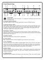
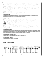
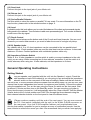
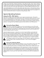
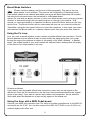
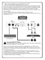
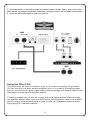
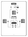
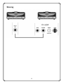
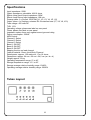
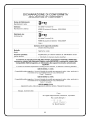
3/100 Top Users' Manual
Release 02
May 2006
Please read this manual carefully before using the amp
How to Read and Use the Information in this Manual
We advise you to read through this manual thoroughly. To keep things simple, we
have designed it in such a way that three different levels of information are
offered for each section.
1st Level
For a short summary of the essential information contained in the
manual, please take the time to read at least those paragraphs marked
with the jet icon. This should take you less than 5 minutes.
2nd Level
If you feel you want to learn about the amp head in more detail without
having to read through the entire manual, read those sections where you
see the jet and car icons. This approach will take you around 10 minutes.
3rd Level
To learn about the amp head in even greater detail (but without having
to read every single part of the manual), read also those sections
where you see the ship icon. Reading the manual at this level will give
you an excellent grounding in the features of the 3/100 Top, and
should take no more than about 25 minutes.
The Valve 3/100 Top - The Highlights!
Shaping Mode
page 10
Boost Mode
page 10
Midi Out
page 13
2
Introduction
Congratulations on choosing the 3/100 Top. It gives us great pleasure to welcome you
as a member of The Valve family. We will be delighted to thank you for placing your
trust in us by providing you with reliable, always-available support to allow you to really tap the potential of this extraordinary amp head.
One of the major challenges faced by any maker of musical instruments is how to
allow musicians to reproduce the precise sound they have in mind. As a guitarist, you
should always - whether in the studio or on stage - be in a position to reproduce your
personal sounds, the ones that you've been working hard to refine and develop in
your head. As musicians and amp makers, our mission is simple: to provide you with
products that, once the gig is under way, you will never have to turn away from the
audience to adjust.
Amplifiers from The Valve are designed to provide you with the map to your sound.
The front and rear panels display tonal capacity only. By reading this instruction
manual you will discover how, with just a little bit of maintenance and care, this amp
head will give you great enjoyment for many years to come.
Warnings
The lightning flash with an arrowhead symbol within a triangle is intended to
alert you about the presence of an un-insulated "dangerous voltages" within
the product's enclosure that may be of sufficient magnitude to constitute a
risk of electric shock to users.
The exclamation point within a triangle is intended to alert the user about
thepresence of important operating and maintenance (servicing) instructions in
the literature that accompanies the product.
3
3/100 TOP
3-channel MIDI amplifier
Table of contents
Introduction
page 3
Packaging and Safety Information
page 5
Front Panel
page 6
Rear Panel
page 7
General Operating Instructions
page 9
page 9
Getting Started
Special Features
page 10
Pr1, Pr2 Switch
page 10
Shaping Mode
page 10
Boost Mode
page 10
Boost Mode Switches
page 11
FX Loop
page 11
MIDI
page 12
Using a MIDI Pedalboard
page 11
Using the MIDI OUT Mode
page 12
Direct Out
page 13
Slaving
page 15
Warranty
page 16
Specification
page 18
4
Packaging Information
On receipt of the package, please check it carefully to ensure that it has not sustained
damage during transit and that there are no missing parts. We recommend that you retain
the packaging material should you need to ship or carry the amp from one place to
another.
Before Using the Amp
1) check that the power outlet is grounded before turning on the amp
2) before turning the amp on, make sure that the power supply specifications on the
back panel conform to the supply where you intend to use the amp
3) do not expose the amp to moisture, direct sunlight, water or high temperatures
4) always use replacement tubes of the same type and rating
5) remove the plug from the socket before replacing a fuse
6) protect your hands when handling hot tubes
7) servicing should only be carried out by qualified technicians
8) never plug the amp into an ungrounded socket
9) before use, give the amp time to acclimatize to the environment in which you intend
to use it
10) keep the amplifier away from children.
Prolonged exposure to sound at high volumes may result in damage to the ears
and/or hearing loss.
Caution!
Never attempt to open the chassis yourself. Only qualified service technicians
should open the chassis. Do not introduce any foreign object into the jacks.
E2 group device according to CEI EN 55103-1 EN 55103-2, following EMC
classification.
Please fill in the following information for warranty purposes and future
reference:
Model
Serial number
Dealer’s address
Dealer’s name
Date of purchase
: The Valve 3/100 Guitar Head
:
:
:
:
Engineered by:
TBE S.r.l.
Via della Tecnica 51/b
40068 San Lazzaro di Savena (Bo)
Italy
Ph: +39 51 6258433
Fax: +39 51 6257784
Email: [email protected]
Web: http://www.the-valve.com
5
Front Panel View
3
4
1 2
5
3
6
7 8
2
5
6
3
8
9
2
5
6
12
16
10 11 13 14 15 17
(1) Input Jack
(Please read up to and including No. 17). Accepts low- and high- input (such as active pickup) levels.
(2) Channel Selection Buttons
Use these buttons to select channels, press twice to select the Boost function.
(3) Channel Selection LEDs
These LEDs, located next to the respective volume controls, light up when the given channel is selected, thus indicating which channel is currently active. Selecting the Clean channel lights up the green LED, selecting the Crunch channel lights up the yellow LED, and
selecting the Lead channel lights up the red LED.
(4) Presence 1 Control
This presence control functions only with the Clean channel, to which it adds definition and
brilliance. Presence can be controlled on the Crunch channel also by using the Pr1/Pr2 switch.
Please please refer to point "7".
(5) Volume Controls
Controls the output level of each channel independently
(6) Tone Controls
Bass, middle and treble controls designed to give maximum tonal variation.
(7) Pr1, Pr2 Switch
Turn this switch to the left to produce a typically British Crunchy sound. Turn it to the right to
beef up the sound by increasing the bottom end. This switch also allows you to process the
Crunch channel's high frequencies through the Clean channel presence knob (switch to Pr1
position) or to the Lead channel presence knob (switch to Pr2 position).
(8) Gain Controls
These are used to control the amount of gain - in other words to adjust the overdrive level
of the Crunch and Lead channels. Turn this control clockwise until the desired amount of
distortion is produced.
(9) Shaping Button
Pushing this button scoops the mid-range on the Lead channel. This is very useful for when
6
you want to switch immediately form a scooped, rhythm sound to go into a screaming solo.
For more information on shaping please refer to the appropriate section on page 10.
(10) Store Switch
Press and hold the 'Store' button to MIDI-store the status of the channel (Boost on or off)
and the shaping function. For more information on MIDI, please refer to the MIDI interface
section on page 12.
(11) Master Control
This is used to set the overall output level of the amplifier.
(12) Boost Led
The blue LED indicates that the Boost Function is selected. It flashes to indicate that the
amplifier has stored one of the programmable functions.
(13) Boost Master
This control acts as a separate adjustable Master Volume for solos. It delivers both volume
(by turning the knob) and gain (by adjusting the trimmer on the chassis). For further
information about adjusting the Boost trimmer, please contact us at [email protected]
(14) Presence 2 Control
This presence control adds definition and brilliance to the sound of the Lead channel.
Presence can be controlled on the Crunch channel also by using the Pr1/Pr2 switch. Please
refer to point “7”.
(15) Stand by Switch
This switch mutes the amp by switching off the high-voltage circuitry while allowing the tubes
filaments to remain warmed up and ready for immediate use. Switching to standby when you
won't be playing for some time helps to increase the life of the tubes.
(16) Power on Indicator Light
The red light is illuminated when the amp is switched on.
(17) Power on Switch
The master on/off switch for the amp.
Rear Panel View
7
1
2
3
4 5 6 8 9
11 12 13 14 15 16 17 18 19 20
10
7
(1) AC Socket
(Please read up to and including No. 20). Connect the supplied AC cord here.
(2 -3) Fuses
The Main fuse protects the amp from damage in case of power tube failure or exter
nal AC fluctuations. The HT fuse protects the high-voltage part of the circuit. If a fuse blows,
it is extremely important to replace it with another fuse of the same type and rating. To prevent any risk of electric shock, it is recommended that you disconnect the power cord before
replacing the fuse. If the fuse blows repeatedly, take your amplifier to your dealer or to a
technician for servicing.
(4) MIDI IN
This socket receives MIDI information from a MIDI-enabled device that is sending commands
to the amplifier (MIDI foot controller, etc). For more information on MIDI, please refer to the
MIDI interface section on page 12.
(5) MIDI OUT/THRU
The MIDI OUT/THRU performs two different functions: when receiving information from the MIDI
IN, this port automatically duplicates the MIDI IN data to make it MIDI THRU. Conversely, if the passive FS-1 foot-switch (supplied with the unit) is connected, this port acts as a MIDI OUT with the
capacity to send "Program Change" data, which can be defined using the set-up display found on
the rear panel. For more information on MIDI, please refer to the MIDI interface section on page 12.
(6) Set Button
Please refer to "MIDI OUT" section on page 13.
(7) 3 Digit Setup Display
Please refer to "MIDI OUT" section on page 13.
(8) Inc (increment) Button
Please refer to "MIDI OUT" section on page 13.
(9) FS-1 Connector
Connect the FS-1 foot-switch (supplied with the unit) here.
(10) Boost Mode Selection
If you like the sound of one channel when the Boost function is switched on (e.g. the Lead
channel), you can select it permanently by moving the switch to the "always on" position. For
more information on the Boost function, please refer to the relevant section on page 11.
(11) “Full Pwr” and “Half Pwr” Switch
This switch determines the overall output power of the amplifier. In the "Full power" position, all four
output tubes are active and the amplifier is generating maximum power. In the "Half power" position,
two of the output tubes are turned off and power is reduced by approximately 30%. This function can
prove very useful in recording studios or small clubs where less power may be what is required. The
low-power setting also produces its own distinctive tone and is worth exploring fully.
(12) Direct Out
Use this output when you want the signal to be passed to an external effects chain and, subsequently, to another power amp in order to give you separate amp-direct processed signals. For
more information on the Direct Out function, please refer to the relevant section on page 14.
8
(13) Send Jack
Connect this jack to the input jack of your effects unit.
(14) Return Jack
Connect this jack to the output jack of your effects unit.
(15) Series/Parallel Selector
Use this switch to select the series or parallel FX Loop mode. For more information on the FX
loop function, please refer to the relevant section on page 11.
(16) Level
In parallel mode, this knob allows you to control the balance of the direct and processed signals
being send to the cabinets. Turn clockwise to add more processed signal. Turn counter-clockwise
to add more of the dry signal.
(17) Depth Control
The depth control enhances the bottom end of the Crunch and Lead channels. You can use it
wherever you need a fatter sound or you want to fatten the sound of a single coil pickup.
(18/19) Speaker Jacks
Any cabinet with 4, 8 or 16 ohm impedance can be connected to the two parallel-wired
speaker outputs. If both speaker jacks are used the total load must be minimum 4 ohms and
maximum 16 ohms. Connect speakers with unshielded speaker cable only..
(20) Impedance Selector Switch
Select 4, 8 or 16 ohm impedance: use this switch to match your amp impedance to the cabinet(s) you are using. When connecting two 8-ohm cabinets, remember to set the switch to 4
ohms, whereas, when using two 16-ohm cabinets, set the impedance to 8 ohms.
General Operating Instructions
Getting Started
Plug the speaker cord (supplied with the unit) into the Speaker 1 output. Check the
ohm impedance load of the cabinet(s) you are going to use and adjust the impedance
selector switch on the rear panel of the amp accordingly. Make sure that all controls
are set to the 12 o'clock position except the Master and the Boost knobs. As you can see, each
channel has its own independent tone control for maximum tone flexibility. Connect the cabinet
using the supplied cord. Turn on the amp using the Power On switch on the front panel. Wait
for around 1 minute and then turn on the Stand By switch. You can now plug your guitar in.
Every time the amp is turned on, it will automatically select the Clean channel. Twist the Master
Volume knob to the 9 o'clock position and PLAY! Run through the three channels using the
black channel selection buttons on the front panel to hear the different tones.
(Please continue reading until the end of the next page). You can now connect
the FS-1 foot-switch (supplied with the unit) to the 9-pole D-SUB connector on
the rear panel. Your new 3/100 amplifier features very sophisticated tone
circuitry that makes it possible for you to produce an array of customized sounds. Use the
tone controls to achieve the sound you want. We recommend that you refrain from applying
9
extreme tone equalization settings. Remember, while playing at high volume levels, lowering
the bass control may improve note definition and increasing the treble and mid controls may help
to project the sound further and cut through the groove. Start by gently twisting the tone controls
to find out how they work, then adjust the presence and control and add the desired level of harmonics and brightness to your sound. Now please select the Crunch or Lead channels, either by
pushing the relevant button once or using the foot-switch. Adjust the tone controls to achieve the
desired effect, just as you did with the Clean channel. Adjust thr Depth control on rear panel. You
can also customize the amount of overdrive by turning the gain control.
Special Operating Features
Using the PR1, PR2 Switch
Note the mini toggle switch above the Crunch channel selection button. This switch
alters the sound to give you two different tones. By turning the switch to the left, you can
produce a typically British Crunch sound. Turning it to the right will "beef up" the sound
by increasing the bottom end. This switch also allows you to process the high frequencies of the Crunch channel through the Clean channel presence knob (switch to the PR1
position) or through the Lead channel presence knob (switch on the PR2 position).
Using the Boost Mode
Once you've mastered the basics, you can concentrate on one of the most
exciting features of this amp: the Boost control. This acts as a separate volume control for
solos and can be set for all channels. Please select one of the three channels. By pressing
the selection button a second time (or the dedicated Boost button on the foot-switch), you
will turn the Boost function on and off.
Adjust the desired amount of volume for your solo using the Boost control and then
press the channel selection switch again to return to the standard channel function.
Every time you reactivate the Boost function (through the selection switch on the front
panel, through the optional foot-switch or through a MIDI pedal board), you will produce
the sound of the selected channel, increased by the volume level set using the Boost
control, together with a small amount of gain. This minimal amount of gain is adjusted
via 3 trimmers located on the amp chassis. DO NOT attempt to adjust the trimmers by
yourself. Please contact a specialist technician or write to us at [email protected].
Using the Shaping Mode
Note the small button that says "Shaping" on top of the middle control of the Lead
channel. This feature creates a sort of hole in the mid range, which is very useful for
powerful scooped rhythm sounds. The shaping function works with the Lead channel only.
Its functionality can be independently set to the Lead channel in both normal mode and
Boost mode. Setting the shaping function is worthwhile when you want, for example, to
switch instantaneously from a scooped rhythm part to a screaming solo (where the midrange comes to the fore). To activate this option, select the Lead channel and switch the
shaping button on, then select the Lead channel with Boost and switch the shaping function off.
10
Boost Mode Switches
(Please continue reading until the end of this paragraph). This part of the rear
panel shows 3 mini switches. They pre-set the functionality of the Boost mode.
Each switch relates to one channel and allows you to pre-set Boost status that will be selected using the front panel button, the foot-switch or a Midi pedal board.
Always on: pre-sets the Boost function to come ON automatically every time the relevant
channel is selected through the front panel buttons or through a foot-switch. *N.B.
should you need momentarily to deselect the Boost, press the Boost button on the footswitch once. The Boost function will be reactivated as soon as you select the channel*.
Selectable: using the front panel buttons to select the channels, in this mode you select
and deselect the Boost mode on a desired channel each time you press that channel.
Using the Fx Loop
First, you have to decide whether to use a series or parallel effects loop connection. The difference between the two effects is that, in series mode, the signal going from your guitar
through the amp to the cabinets is subject to the quality of the effect, whereas - in parallel
mode - the original sound of your amp reaches the cabinets intact, meaning that the quality
of the effect is not compromised in any way.
Proceed as follows:
If you want to use the parallel effects loop connection, select only the wet signal on the
effects unit. Now use the Level knob to mix the level of the processed signal to the original
sound of your amp. If you want to use the series effect loop connection, set the switch to
Series and select the desired mix of wet and dry signal on the effects unit.
Using the Amp with a MIDI Pedal-board
Connect your MIDI foot-controller from The Valve or another manufacturer to the MIDI IN
connection on the 3/100. You can also connect the MIDI OUT/THRU on the 3/100 to an
external digital multi-effect unit.
11
1 - Select the required patch on your pedal board/midi controller.
2 - Select the Channel/Boost/Shaping settings on your amp.
3 - Press the store button. The blue Boost LED will start to flash, indicating that the store
function is in process - hold the Store button until it stops flashing to complete the storing
process. This operation lasts about 4 seconds. If for some reason you release the button
before the blue LED stops flashing, the store operation will be cancelled. The MIDI
OUT/THRU function automatically functions as MIDI THRU every time a message is received via the MIDI
IN port. The MIDI firmware can be updated through the DB-9 connector
located on the top of the chassis. For more info about upgrades, please contact us at: [email protected].
Using the MIDI OUT Mode
This amplifier allows you to also control other MIDI devices even without a MIDI controller
simply by using the supplied FS-1 foot-switch pedal.
Once you have selected the desired amp function (Channel/Boost, e.g. Channel 3 with
Boost) on the front panel or using the foot-switch (supplied with the unit), you can use the 3digit display on the back panel to select the desired patch of a multi-effect device and store it.
Please proceed as follows:
1 - Choose the amp channel with or without Boost (e.g. Channel 3 with Boost). The rear
panel displays "ch3." where "ch" is short for "channel", "3" indicates that you have selected
channel 3 and the "dot" means that the "Boost" function is active.
2 - Push the left button below the display. The display shows the patch number assigned to
the amplifier's status (channel 3 with Boost).
12
3 - Push the button on the right to select the desired patch (reverb, delays, etc) on the multieffect device. By keeping the button depressed, the patch number will increase incrementally.
4 - press the left button again to store your setting.
Using the Direct Out
This output may be used to connect a tuner or to connect to another FX processor.
You can also use it to slave another amplifier for bi or tri-amping. Bi-amping means
that you are running the guitar signal without effects through one speaker cabinet and
with effects through another speaker cabinet.
Tri-amping means that you are the running the guitar signal without effects through
one speaker cabinet while using the direct out to send signals to a stereo multi-effect
device running a stereo power amp in order to give you a separate amp-processed
signal going to 2 different cabinets.
13
14
Slaving
15
Warranty
Thank you for purchasing a product from THE VALVE. We are sure that you will be more
than satisfied with your choice. Should your amplifier need in-warranty servicing, please
contact the dealer where it was purchased or, alternatively, contact THE VALVE directly. In
order to avoid any unnecessary inconvenience, we recommend that you read through your
warranty carefully before contacting your dealer or our authorized service department.
Your Warranty
THE VALVE hereby guarantees that the product will remain free from defects of
materials and workmanship for a period of 2 (two) years from the date of purchase. In
order to receive warranty service, you should provide proof of retail purchase. The tubes
are not covered at all under the terms of this warranty, while the speakers are covered for
a period of 90 days from the date of purchase.
1) This warranty will be considered valid only when the original invoice or sales receipt
(indicating the date of purchase, product type and dealer's name) is presented together
with the defective product.
2) The cost of transporting the product to the service center will not be covered unless specifically stated otherwise in this warranty.
3) This warranty does not cover:
a) adjustments to customer-operated controls as shown in the model's instruction manual,
or products that have been altered or replaced, or products on which the serial number has
been removed or is illegible.
b) the physical appearance of accessory items including, but not limited
to, cabinet parts and knobs.
c) the unpacking, setting-up, installation or removal and
reinstallation of products under repair.
d) any loudspeaker drivers that have been damaged due to exposure to excessive heat, or
physical damage such as moisture, rips, tears, shock or transportation.
e) repairs or replacements necessitated by any cause beyond the control of THE VALVE,
including, but not limited to, modifications or adjustments made to the product without
authorization, such as the use of damaged or broken tubes, incorrect line voltage, inadequate maintenance, modification or repair by the user, abuse, misuse, neglect, accident,
fire, or any other cause beyond the control of THE VALVE.
4) Warranty service is only available by contacting an Authorized Repair Service or by
returning the unit to THE VALVE or to a distributor with prior authorization. The Valve
Amplifiers will not accept any goods that have been returned without authorization. If your
product is still under warranty, you must contact (in writing) the distributor or dealer where
you purchased the product and, once the dealer gives you authorization for the goods to
be returned, THE VALVE will organize shipping and pay the costs directly.
For any info, please call:
THE VALVE AMPLIFIERS
Ph: +39 51 6258433
Fax: +39 51 6257784
Email: [email protected]
16
DISCLAIMER
Some countries, states, and provinces do not allow the exclusion or limitation of implied warranties or the limitation of incidental or consequential damages for certain products supplied
to consumers, or the limitation of liability for personal injury, so the above limitations and
exclusions may be limited in the extent to which they apply to you. When the implied warranties are not allowed to be excluded in their entirety, they will be limited to the duration of the
applicable written warranty. This warranty gives you specific legal rights that may vary depending on local law. If you have any questions about this warranty or service received or if you
need assistance in locating an Authorized Service Center, please contact:
THE VALVE
Engineered by:
TBE S.r.l.
Via della Tecnica 51/b
40068 San Lazzaro di Savena (Bo)
Italy
17
Specifications
Input impedance: 500K
Output impedance: selectable, 4/8/16 ohms
Effects Loop Send Output impedance: 280K
Effects Loop Return Input impedance: 10K min
Preamp tubes: 6 x Sovtek 12AX7WA (V1, V2, V3, V4, V5, V6)
Output tubes: 4 x Svetlana selected EL-34 matched sets (V7, V8, V9, V10)
Tube voltage: 450 volts DC
THD: 1,5%
Operating voltage: please see label on rear panel
Fuses: please see label on rear panel
Important: replace fuses only against same type and rating
Power consumption: 320VA
MIDI Control:
Channel 1 Select
Channel 2 Select
Channel 3 Select
Boost 1 ON-OFF
Boost 2 ON-OFF
Boost 3 ON-OFF
Shaping function on lead channel
Cabinet material: 18mm. thick Birch Plywood
Rated power: approx: 120 watts at 4, 8 or 16 ohms;
Dimensions: approx: 64 cm x 26 cm x 24,5 cm (w x d x h)
Weight: approx: 20 kg
Operating temperature range: 0° to 40°
Storage temperature range: -10° to 60°
Storage average relative humidity range: 10/90%
Operating average relative humidity range: 30/80%
Tubes Layout
18
19
Engineered by:
TBE S.r.l.
Via della Tecnica 51/b
40068 San Lazzaro di Savena (Bo)
Italy
Ph: +39 51 6258433 - Fax: +39 51 6257784
Email: [email protected] - Web: http://www.the-valve.com