1
Ver 1, Nov 2004
SPICA Fuel Injection Roadside Fault Analysis and Repair
This guide is intended to aid the owner-mechanic in understanding and diagnosing Alfa Romeo SPICA injection pump malfunctions. It is not a substitute for the
official factory technical publications. No claim to absolute accuracy or utility is expressed or implied. The reader uses this guide at his own risk.
This section provides information for fault diagnosis and describes some simple improvised roadside repairs
that may allow self-recovery of the car to home or to a mechanic. The SPICA injection pump is generally
very reliable. There is only one injection pump failure that is serious enough to cause engine stoppage and is
common enough to be of practical concern. By far, most problems experienced by SPICA owners are fuel
supply related and not within the injection pump itself. When troubleshooting, rule out ignition causes first,
then fuel supply, and only then, suspect the injection pump. The following are some possible injection pump
failure modes that might cause sudden engine failure:
1. Broken Compensator Link Retaining Spring. (somewhat common, especially in poorly maintained cars)
2. Shorted Fuel Cutoff Microswitch. (somewhat common in old pumps)
3. Broken Injection Pump Drive Belt (uncommon)
4. Broken Hairspring Clip (very uncommon)
5. Broken Barometric Compensator Bellows (very uncommon)
Given that many of these SPICA pumps have been in service for more than 30 years, it's not surprising that
some components such as Compensator Link Retaining Springs have corroded or fatigued over the years and
occasionally fail. The same is true of Fuel Cutoff Microswitches. That said, if you carry a few simple tools
and improvised repair parts in the trunk, you should never be stranded by your SPICA system. I recommend
carrying the following tools and parts with you in your trunk. Everything will fit it a small pouch.
1.
2.
3.
4.
5.
6.
7.
8.
Vice-Grips
Multi-screwdriver with assorted tips
Needle-nose pliers with integral wire cutter.
Bent-nose forceps
2' length of mechanics wire
A few rubber bands
¼" x 4" carriage bolt w/ 2 nuts
Small plastic wire ties
This guide assumes that you have a cursory knowledge of the SPICA system and know the location of basic
components, their nomenclature, and basic operating theory. When confronted with a malfunction on-theroad, the first action is to find a safe place to park the car. Turn the ignition OFF and look under the car for
any leaks. An engine malfunction is more likely to be electrical in nature rather than fuel, so consider that
possibility first. Turn the ignition key on momentarily and listen for the whine of the fuel pump. If you don't
hear anything, check the fuse. (by the driver's left knee, separate small, two-fuse, fusebox).
If necessary, remove the air cleaner box and visually check all components for any obvious defects such as:
1. Fuel leaks from hoses, fittings, front fuel filter, injection pump, or SPICA high-pressure metal fuel tubes.
2. Wires detached from their terminals (fuel low -pressure switch, cold start solenoid, and fuel cutoff
solenoid, ignition wires, spade terminal underneath distributor base, coil connections).
3. Burnt wiring.
1
4. Assuming the engine is at operating temperature, check that the throttle arm on the rear of the injection
pump is almost touching the reference screw. If there is a large gap, the thermostatic actuator may have
failed causing a grossly over-rich mixture.
5. Throttle cable attached and in good condition (casing not melted). A deformed/melted throttle cable
casing can indicate a bad engine ground strap since the engine will then try and ground itself through the
throttle cable. Because of its high electrical resistance, the cable will get very hot and melt the casing.
6. Rod end links attached and in good condition. Look CLOSELY. A tiny crack in the rod end boss may not
be visually obvious, but still allow the rod threads to slip when tension is applied. A clue might be a locknut
that is separated from the rod end by several threads.
7. With throttle sitting on the idle throttle stop, confirm the throttle butterflies are closed. Again, if they are
not, it may indicate a slipped throttle rod end.
8. Injection pump belt not broken.
9. Air Cleaner air intake not clogged, and air cleaner elements serviceable.
FAULT ANALYSIS
To proceed with further troubleshooting, you'll need a screwdriver to remove the four hose clamps and a
10mm wrench/socket or adjustable wrench to remove the two nuts holding the air box straps.
I. SYMPTOM:
Flashing or steady fuel low-pressure light. (See section on Fuel Supply System Fault Diagnostics for a
more in-depth troubleshooting procedure)
POSSIBLE CAUSES:
1. Clogged fuel filter.
2. Weak or failing fuel supply pump.
3. Fuel overheated causing supply pump cavitation.
5. Clogged (suction) fuel line from tank to pump.
4. Fuel tank vent clogged.
TOOLS REQUIRED: Screwdriver; 10mm wrench/socket/adjustable wrench (to remove air cleaner box);
Vice-Grips or extra hose clamp
FAULTS & EMERGENCY FIXES (in order of likelihood):
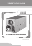
1. Clogged fuel filter. Change the rear filter with the spare you always keep in the trunk. A clogged fuel
filter probably will be slowly progressive, so you should be able to limp-in somewhere. See Fig 1.
LIMP-IN: If you do not have a correct replacement filter, you may be able to check the nearest auto
parts store and fit any high-flow in-line filter that will fit the fuel line. As an extreme measure, you may also
be able to bypass the bad filter altogether and rely solely on the front filter. If you do this, at first opportunity
change both front and rear filters and flush the lines and fuel supply pump up to the front fuel filter. (WIX
33299 or equivalent). Ends should fit a ½” (12mm) ID fuel line.
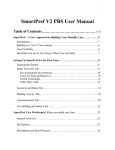
2. Weak or failing fuel supply pump. Partially squeeze-off the rubber fuel line from the forward most (exit)
fuel nipple on the SPICA injection pump (fuel return line) and see if the fuel low pressure light extinguishes.
Squeeze just enough until the low-pressure light goes out. If the light extinguished, the pump may be failing.
2
If the reason is overheated fuel, causing vapor lock/cavitation, this will only make it WORSE. Adding cool
fuel may temporarily help a failing pump to put out more pressure. See Fig 2.
LIMP-IN: An extra small hose clamp, stout wire tie, an adjustable wrench, or Vice-Grips can be
used to partially squeeze the FI pump exit hose and may allow a weak pump to provide enough fuel pressure
to extinguish the low pressure warning light and run the engine. However, this is a limp-in fix ONLY. Do
not operate the engine any longer than necessary with a weak supply pump. The injection pump needs high
fuel flow to cool it and prevent premature wear. Expect imminent total failure of the supply pump.
CAUTION
DO NOT COMPLETELY BLOCK OFF THE LINE. This will
deadhead the fuel pump, which can create pressures in excess of
rubber fuel line ratings. A burst or leaking line could cause a fire.
Fig 1. Rear Fuel Filter
3. Fuel tank vent clogged. Slowly remove filler cap and
listen for hissing indicating that there is negative
pressure in the tank. If there is, leave cap loosely
fastened. Check low-pressure light is OUT.
LIMP-IN: Loosen fuel filler cap to allow the
fuel tank to repressurize to ambient conditions.
Fig 2. Fuel Supply Pump. Pictured pump is a Bosch
L-Jet type. You may have the older model with 3
ports on one end, or two ports in an "L" shape, or
even an original AEG pump.
4. Fuel overheated causing supply pump vapor lock/cavitation. Overheated fuel, especially in '69
-'76 model
systems, can cause vapor lock and cavitation in the fuel supply pump. Hot ambient temperatures, low fuel
levels in the fuel tank, heat reflected into the fuel tank from hot pavements, and long periods of high-speed
operation can all contribute to overheated fuel. Later model systems were retrofitted with in-tank fuel boost
pumps that make those cars much less vulnerable. Since the injection pump uses fuel for cooling, operating
with low fuel levels make for less volume of fuel to absorb the heat.
3
.
LIMP-IN: Turn off engine and let remaining fuel cool or add cold fuel to tank.
5. Clogged fuel feed line from the tank to fuel supply pump. In cars that sat derelict for long periods of time,
it is quite possible that sludge, varnish, rust, or other foreign materials have contaminated the fuel tank. In
tanks that sit derelict, rust often forms in the space above the fuel level. If the fuel level is just right, varnish
can form in the end of the return line tube and prevent fuel from returning to the fuel tank when the supply
pump is operating. This, in effect, "deadheads" the pump, causes very high fuel line pressures, can cause
vapor lock symptoms, and could conceivably cause a dangerous hose rupture.
LIMP-IN: Probably none, although you might try and turn the key off (stop fuel supply pump
suction in the line) and shake the car to try and dislodge the blockage. Adding fuel to the tank may help also.
II. SYMPTOM:
Engine suddenly dies or runs badly while at partial-throttle/low speeds (fluffy/lean throttle
response, backfiring through intakes, no power/torque), but runs better at high throttle
settings if you can get the engine up to rpm.
POSSIBLE CAUSE: Broken Compensator
Link Retaining Spring
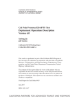
VERIFICATON: Remove the Barometric
Compensator and look for a broken retaining
spring. See Fig 3. You can use your finger to
push on the spring to verify that it's attached
at the top and bottom. See Fig 4.
TOOLS REQUIRED:
Method 1. Reattach spring method:
Screwdriver, wrench to remove air box, bentnose forceps or bent-nose needle nose pliers.
Method 2. Temp spring replacement method:
Screwdriver, wrench to remove air box, bentnose forceps or bent-nose needle-nose pliers,
mechanics wire, rubber bands
EMERGENCY FIX:
Fig 3. Removing the Barometric Compensator. To remove the BC
simply remove the three machine screws and lift the BC out. It's not
attached to anything inside.
Method 1, Reattach Spring:
If there's enough good spring attached to the link arm at the bottom, oyu may be able to reach down, grab
the spring and reattach it to the top retaining screw.
a. Remove Barometric Compensator (3 screws) See Fig 3.
4
b. Grab upper end of spring with forceps. See Figs 4
through 8. Pull upper end up to meet the retaining screw that goes
through the top of the pump body. Position the screw so it's just
through the casting, then hold the spring up against the screw gently
and turn the screw to thread it on. It may help to reposition the link
arm at the upper limit of the vertical notched lever. This will allow
you not to have to put so much upward tension on the spring while
reattaching it. When done, reposition the compensator link to about
middle (7th notch down). To reposition the compensator link, push
rearward at the place indicated in Fig 7., lift the link then allow it to
go forward again. Use caution when doing this with T237/1 ('69
model) pumps. Those pumps do not have an upper stop to prevent
the compensator link arm from coming off the vertical notched
lever. When done, reposition the link arm to about the middle
position. This will allow the engine to start and run. Accelerate the
engine to 4000 rpm then closing the throttle will automatically reset
the compensator link to the correct position.
Fig 4. Compensator Link Retaining Spring.
Fig 5. Reattaching Retaining Spring to upper machine screw.
Fig 6. Retaining Spring upper attachment
point
Fig 7. Resetting Compensator Link. Push rearwards to
disengage from notched lever, move up or down, then let
it come back forward to engage the notched lever again.
Cutaway shown is a '69 model pump. Newer pumps have
an upper stop to prevent the compensator link from
coming off-track.
5
Fig 8. Inside cutaway view of forceps grasping retaining
spring. Note upper attachment point (machine screw) just
poking through the casting.
Fig 9. Cutaway view of Method 2 temporary repair.
Method 2, Temporary Spring Replacement:
If the spring is broken too far down to stretch the remaining spring back to the top without excessive force,
or you don't have some bent nose forceps, you may have to imp
rovise. Some mechanics wire or a
straightened paperclip and a rubber band will make a workable substitute.
a. Remove the retaining screw on top. Some portion of the spring is probably still attached to the
retaining screw inside, so that will have to be removed. Reach in and somehow keep the spring from turning
while you remove the screw. Caution, the end of the spring is very small and can puncture the skin if you're
not careful or using a rag or something to grip it. If unable, you might try just force to remove the screw. The
broken spring portion will probably just unwind off the screw as it's withdrawn. It's ruined anyway so that's
no loss. Try to keep the broken end from falling into the bottom of the pump. If it does, don't worry about it.
It will sit harmlessly in the bottom of the logic section.
b. Next insert a piece of wire or paperclip through the screw hole and make a hook in the end, after
you pass it through the hole. Hook it around the bottom of the compensator link as shown. (See Fig 9)
c. Make a loop on the top portion and rubber band to something in the engine to provide just a slight
bit of upward tension on the compensator arm. Only a slight bit of tension is needed.
d. If the compensator link has fallen to the bottom of its range, you should reset it to about the middle
of the range. Do this by putting your finger on the compensator link from the Barometric Compensator
cavity and push rearwards on the link. You can then move the link up and down and reset it on a midrange
notch. See Fig 7.
e. Reinstall the Barometric Compensator.
f. If engine performance is still poor, rev the engine to 3000-4000 rpm and let off the throttle to reset
the compensator link.
6
g. Drive to a place where the retaining spring can be replaced properly. Do not consider this any more
than a very temporary repair. OEM springs are no longer available, but duplicate springs can be made by a
good gunsmith.
Method 3, Reset and Be Careful:
You can remove the Barometric Compensator and manually reset the compensator link to a nominal
position (7th notch from top) See Fig 7. You may then drive with very slow throttle movements, being
especially careful NOT to fully close the throttle from higher engine rpms. Fully closing the throttle from
high rpms allows the compensator link to disengage the vertical notched lever (to reset itself). With a broken
compensator link retaining spring, the compensator link arm will fall to the bottom of the range, leaning the
mixture to the point of stalling the engine.
LIMP-IN: Even without resetting the compensator link, you may be able to continue driving by
using a throttle position at which the engine will run. While no means a satisfactory engine running
condition, it may allow you to limp-in to somewhere safe. Also, keep in mind that the mixture will be very
lean and detonation could damage the engine.
III. SYMPTOM:
Erratic engine operation. Engine runs badly or stalls at idle/low throttle settings but runs better at
high throttle settings. May have a very high idle. Engine may stop altogether.
POSSIBLE CAUSE: Cracked or completely broken rod end (plastic piece on end of long or short rod)
resulting in a change of length of the rod. See Fig. 10.
TOOLS REQUIRED: Plastic wire tie or mechanics wire.
EMERGENCY FIX: The locking nut for the plastic end piece is probably still in the correct position. Move
the end piece to the correct position and secure it in place with the plastic wire tie. See Fig 11. With the
short rod the correct position will be with the throttle in the idle position and the throttle butterflies “just”
closed in their bores. The correct long rod position will be so the throttle arm on the rear of the injection
pump is sitting in its natural position (very close to the reference screw)
Fig 10. Cracked Rod End
LIMP-IN: Resetting the broken rod
end may result in it not being in the absolute
correct position resulting in a miscoordination of the fuel-air relationship. If
the car will run without detonation you can
limp in somewhere safe. If you are getting
pre-ignition (knocking) restrict your throttle
setting to eliminate knock, or do not run the
engine. Detonation is deadly to
hemispherical combustion chamber engines
like Alfas.
Fig 11. Cracked Rod End temporary
repair with plastic wire tie.
7
IV. SYMPTOM:
Engine stops suddenly or exhibits random "cutting-out." Restart attempts fail, although the engine
may initially fire, but then die as the key switch is released from the start to the run position.
1. POSSIBLE CAUSE: Shorted Fuel Cutoff Solenoid (FCS) microswitch on bottom of pump causing
steady current to be delivered to the FCS, thus cutting off all fuel delivery. Restart attempts may result in
initial firing until the key switch is released because with the key switch in the "START" position, current is
cutoff from the FCS microswitch. Thus, there is no power to the shorted microswitch. When the key switch
is released to “RUN,” power is restored to the shorted microswitch and the FCS again cuts off the fuel.
TOOLS REQUIRED: None
EMERGENCY FIX: Do either #1 or #2 below:
1. Remove fuse #6. This will cut the power to the FCS, but also to the backup lights and the “Fasten Seat
Belt,” “Brake" warning light, and “Throttle” warning light on the center console.
or
2. See Figs 12 and 13. Disconnect the wire from the spade terminal of the FCS (forward-most actuator on
the mid-top of the injection pump). Tape and secure the wire end so it won’t short out against anything. This
wire can be reached without removing the airbox.
The redundant internal fuel cutoff mechanism should operate the pump normally with perhaps a bit of
burbling or backfiring on closed throttle deceleration. If after disconnecting the wire, the engine starts and
runs normally, no other action is necessary. Replacing the microswitch is not absolutely necessary. It is also
very possible that the two wires running to the microswitch have been twisted; the insulation rubbed off by
vibration, and shorting the FCS Microswitch to a permanent "on" mode.
LIMP-IN: N/A
Fig 12. Fuel Cutoff circuit showing wires from chassis to Microswitch to
Fuel Cutoff Solenoid (FCS). FCS circuit energized via fuse #6.
8
Fig 13. FCS wiring detail.
V. SYMPTOM:
Engine fails while running or fails to start. Seems to be a very lean mixture condition.
1. POSSIBLE CAUSE:
Failed Barometric Compensator. This is very uncommon. The Barometric Compensator is a sealed
bellows unit that expands or contracts with absolute atmospheric pressure, thus enriching or leaning the
mixture for optimum performance. If this bellows loses its seal, there is a spring inside that will expand the
bellows from a normal approximately 27mm to about 40mm. See Figs 14 & 15. The appearance change will
be very obvious. The unit will look very extended. When this happens the greatly expanded Barometric
Compensator will reset the compensator arm link very far down and greatly lean the mixture (like the engine
was trying to operate at a VERY high altitude). It will likely lean the mixture to the point of stopping the
engine.
Fig 14. Barometric Compensator Normal Extension
Fig 15. Barometric Compensator Abnormal Extension
(simulated). An actual failed BC will greatly extend
and reposition the Compensator Link Arm full down
(fully lean).
9
TOOLS REQUIRED: Screwdriver, pliers, ¼” bolt, 2 nuts
ROUTINE FIX: Replace the Barometric Compensator
EMERGENCY FIX: Remove the Barometric Compensator from the top
of the injection pump (3 screws). Carefully lift out the bellows assembly
(it’s not attached to anything inside the pump). If it’s obvious that the
bellows has failed, remove the bellows unit from its mounting plate and
substitute a ¼" x 3" min. length bolt in the top plate’s hole. See Fig 16.
The bolt should be 27mm long from the bottom of the plate to the end of
the bolt. If possible, the bolt’s end should be rounded and smoothed as
much as practical, since it will slide along the surface of the compensator
link arm.
Fig 16. Substitute BC made
from ¼" bolt and 2 nuts
LIMP-IN: Two limp-in modes are possible.
1. Mode 1, Running with Barometric Compensator Removed:
Remove the BC and reset the compensator manually to about the 7th notch on the vertical notched lever.
This can be done by removing the rear inspection plate and looking with a mirror. Much easier is to reach
down thru the BC cavity, pull the compensator link to the rear, then raise it to full up and release. See Fig. 7.
Next push directly down on the link and count 4 clicks. Since the full up position is about at the #3 notch, 4
clicks down will be the 7th notch. Remember, this is an emergency limp-in measure. To prevent wear on the
vertical notched lever and the hairspring clip, you don't want to do this any more than necessary. See Fig. 19.
If able, remove the BC bellows from the mounting plate and reinstall the plate. The small hole left by
the bellows shaft won't be a problem. When operating the engine like this, use great caution to be very
incremental with your use of the throttle. Do NOT snap the throttle closed or the arm will reset its notch
position. If this happens the compensator link spring will draw the compensator link up, thus greatly
enriching the mixture. If this happens, simply manually reset the link arm to about the 7th notch again.
Fig 17. Dummy BC installed in cutaway
of logic section. It is essentially a "fixed"
BC now and will not adjust the pump
mixture for changes in altitude and air
density. Adjusting the length so as to
engage the 7th notch of the vertical
notched lever. (nominally 27 mm), will
put it close enough for the engine to run.
Fig 18. Dummy BC installed in car's
injection pump.
10
2. Mode 2, Barometric Compensator Removed:
Remove the BC from it's mounting plate and substitute a ¼" bolt. See Figs 17 and 18. Set the length of the
bolt beneath the mounting plate to just touch the compensator link arm when positioned at the 7th notch on
the vertical notched lever.
Fig 19. Cutaway view of Resetting the Compensator Link on the Vertical
Notched Lever. In the event of a broken Compensator Link Retaining Spring
or a hyper-extended Barometric Compensator bellows, the Compensator
Link will probably drop to the bottom of the vertical notched lever (full
lean), as demonstrated in this photo. To reset the compensator link arm to a
useable setting on the vertical notched lever, simply remove the Barometric
Compensator, reach in with your finger and pull slightly back, then up, then
let the link back forward to engage a notch slightly higher than the middle
position. The engine must be warm or a dummy TA fitted to ensure that the
throttle arm is close to the reference screw (pump gap). When the engine is
cold, the TA moves the vertical notched lever rearwards and makes it very
hard to manually move the link rearwards enough to disengage the notched
lever. Drive using very slow throttle movement. The goal is not to put the 3D
cam in the high rpm, closed throttle regime. That's when the Compensator
Link is released from the Vertical Notched Lever and allowed to reset itself
according to the upward stop provided by the Barometric Compensator
POSSIBLE CAUSE:
Broken hairspring clip on end of rack link. This hairspring clip engages the Barometric Compensator in
the correct notch on the vertical notched lever. The Vertical Notched Lever is the lever that transfers the
driver’s throttle commands to the pump section. If this hairspring clip breaks or comes off, the compensator
link will go full forward to the fuel cutoff position. Access to the hairspring clip is through the inspection
plate on the rear of the pump.
TOOLS REQUIRED: Screwdriver. Mirror. Needle-nose pliers. Very thin piece of spring wire or safety pin.
EMERGENCY FIX: Probably none. Theoretically, you could get a very thin piece of stiff wire (.023"
diameter) and make a temporary hairspring clip. Some sewing pins are stiff enough and the correct diameter
to be used, then both ends bent as retainers. Sewing needles are generally too brittle to bend. However, the
durability of this temporary repair is highly questionable and a proper pin should be obtained as soon as
possible. You would also probably have to remove the Barometric Compensator (triangular plate on top of
pump, it will just lift out after removing the three screws). Installing an improvised hairspring clip is very
difficult in-situ given the awkward position of the access port and the tiny size of the spring and holes.
However, if you were able to, the clip should be installed in the center of the three possible holes ('71
-'81
models, the lower rear in '69 models), and compensator link positione
d on the 7th notch of the vertical
notched link. If you attempt to install a new spring clip or makeshift substitute in -situ, you should tie off the
clip to thread or fishing line in the likely event that you inadvertently drop the clip . . . especially inside the
pump. The exact notch is really dependent on the barometer setting that you’re at, but the 7 th notch (slightly
higher than the middle) should at least allow the engine to start and run. After that, rev the engine to 30004000 rpm and snap the throttle closed. When the throttle is closed from a high rpm, the Barometric
Compensator guides the Compensator Link to reset itself to the correct “notch” on the Vertical Notched
Lever. If you have access to a few tools and a temporary work area, you could remove the FI pump from the
engine and easily replace the spring clip. See section on pump removal.
11
Fig 20. Hairspring Clip as seen
through the rear inspection port of the
FI pump. If it breaks, the Compensator
Link Arm (AKA Rack Link) will go
full forward (lean fuel cutoff) and the
engine will stop. No throttle control is
possible since all driver throttle inputs
are translated through the Vertical
Notched Lever. There are three
possible holes to place the Hairspring
Clip. It should go into the middle hole.
Diameter of the Hairspring Clip is
.025", so any emergency substitute
must be that or slightly smaller.
3. POSSIBLE CAUSE:
Broken injection pump drive belt. The drive belt is very sturdy, however, it is relatively unresilient. If a
piece of foreign material (distributor hold-down nut, for instance) fouls the belt, it is likely to snap rather
than stretch.
TOOLS REQUIRED:
Spider/GTV/Berlina models:
a. 10mm wrench to remove the pump cover
b. Two 17mm wrenches and 13mm wrench (to remove alternator/water pump V-belt).
Alfetta models with a lipped front pulley and air pump driven off SPICA pulley:
a. Same as above, except additional tools to loosen air pump (if installed).
b. Very compact gear puller or steering wheel puller to remove injection pump pulley. The
pulley will likely be very hard to pull off its keyed shaft.
Instructions to reset pump timing. (Set #4 cylinder to TDC on power stroke, then reverse engine rotation
(CCW as viewed front to rear) back to “I” setting on crankshaft pulley. Line up timing index marks on front
of injection pump and pulley. This equates to 70 degrees before the #1 cylinder starts its intake stroke.
EMERGENCY FIX: None unless you have a spare drive belt. If you have a spare belt, installation is
relatively easy on a Spider, and very difficult on a Alfetta.
12
SPIDER/GTV/Berlina
1. Remove fan belt.
2. Time injection pump to engine. First, set the engine to "P" (TDC) at
the beginning of the #4 (NUMBER FOUR) cylinder power stroke, then
rotate the engine CCW (as you'relooking towards the rear of the car
from the front) to the "I" mark (70 deg BTDC). Next line up the index
marks on the front of the injection pump body and pulley as shown in
Fig. 21. Install the new belt on the crankshaft pulley first. The belt will
slip through the small slit between the crankshaft and the front cover.
Then, without changing the position of the crankshaft or injection pump
pulley, slip the new timing belt onto the injection pump pulley. Do not
use levers or sharp objects. Using some WD-40 is ok.
Alfetta
1. Similar to the above, except that you will need to remove the air
pump drive belt and injection pump pulley to get the belt on over the
high lip on the pulley. The pulley is on a tapered splined shaft and
unless it's been removed rece
ntly or has anti-seize on it, it's likely to
require a gear puller and radiator removal to gain access for the gear
puller.
Fig 21. Injection Pump Timing Marks
VI. SYMPTOM: Engine runs poorly. Runs very rich. May have black smoke out the tailpipe that
smells like fuel.
1. POSSIBLE CAUSE: Failed Thermostatic Actuator (T/A).
A failed T/A is usually characterized by a rich running condition and perhaps a fast idle. If the T/A loses its
fluid, it will not extend fully and the injection pump will stay in a cold running enriched condition.
TOOLS REQUIRED: Screwdriver. Dummy actuator.
Remove the center T/A support and the lower part of the T/A from the injection pump. Do not remove the
upper part that fits in the coolant jacket on the intake manifold. Securely tape, wire, or strap the lower part of
the TA to the injection pump to prevent the thin tube from being stressed by engine vibration. You want to
prevent breaking the TA's tubing. Next, insert a dummy TA set to the correct length for your pump's year.
'69
-'76 model years, T237/
1 thru 260 ........ 27mm
'76
-'81 model years, T260/1 thru 265 ........ 29mm
13
Fabrication of Emergency Substitute T/A: A makeshift T/A is easily made from commonly available
materials. A ¼" x 2" or longer machine screw or bolt, two nuts, and a washer is all that is needed to fabricate
a makeshift substitute T/A. Anything that will push down on the adjustment mechanism by 27/29mm and be
held in by at least one of the T/A hold-down screws will suffice.
Fig 22. Emergency Substitute TA
consisting of ¼" x 3" stove bolt, two
nuts, and washer. Nuts adjusted to
give correct length.
Fig 23. Emergency
Substitute T/A
Note filed off edges on
washer in order to fit width
of existing machine screws
Fig 24. Emergency Substitute T/A
installed. Note inoperative TA secured to
prevent damage to TA pipe.
2. POSSIBLE CAUSE: Stuck Cold Start Solenoid
TOOLS REQUIRED: Screwdriver.
The Cold-Start Solenoid (CSS) is the "can" on the top rear of the
pump with a spade terminal on top. It momentarily enriches the
mixture for starts by drawing current from the starter solenoid
when the key is in the "start" position. When the key is turned to
"start" the solenoid energizes and pulls up on the rod/hydraulic
piston assembly with an audible "click." When the key is
released, the solenoid releases, but a slightly delaying hydraulic
action allow the enriching mechanism to slowly taper off in the
space of a second or two. The plastic piece on the bottom of the
CSS rod can sometimes swell and stick, causing a continual
enrichment.
If the problem is a sticky CSS, you may be able to free it with a
light rap from a plastic hammer on the rear of the logic section.
If that doesn’t work, and the CSS is really stuck, you may be able
to free it by removing the inspection cover on the rear of the
Fig 25. Freeing Stuck Cold Start Solenoid.
Remove rear inspection plate, then push
pump, taking a screwdriver and pushing down on the rod that the
down on CSS Rod as pictured. CSS Rod
CSS connects to. Some spray lubricant, such as WD-40 may help
only moves about a ¼".
also if the pump logic section has not been maintained
adequately. After freeing the stuck CSS, leave the CSS wire disconnected and wrapped to prevent a short.
The CSS is not absolutely essential to starting the engine, and leaving it disconnected will not damage the FI
pump. If starting is difficult, spray a little starting fluid (ether) into the opened airbox. That will help the
engine to initially fire.
14
IV. SYMPTOM:
Engine will not start, or is balky at start attempts and smells of raw fuel.
POSSIBLE CAUSE: Flooded Engine
If a start has failed and you smell gas, it’s likely you inadvertently flooded the engine. To clear a flood on a
SPICA injected car:
1. Wait it out. Holding the accelerator pedal down all the way may do more harm than good due to the fact
that the fuel injection pump will deliver even more fuel.
OR
2. Remove and dry the spark plugs. Blow some air in the cylinders.
OR
3. To clear a flood you could try disconnecting the long link (to the FI pump throttle) at the relay crank,
pulling the fuel supply pump fuse, then open the throttle butterflies all the way while cranking the engine.
This will introduce much more air into the cylinders with only a little fuel. Once the engine appears to fire or
clear, reconnect the long link, replace the fuel supply pump fuse, and try a start.
PERMANENT INJECTION PUMP REPAIRS
The procedures outlined in the guide are intended to be temporary. There are some permanent repairs that a
skilled owner-mechanic can perform, such as a microswitch replacement. However, more extensive repairs,
especially ones that require the pump to be opened, should be referred to a professional. The premier expert
and rebuilder of SPICA Injection Pumps is Ingram Enterprises (www.wesingram.com).
Comments or suggestions concerning this guide should be addressed to:
John Stewart, email, [email protected].
15