1
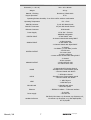
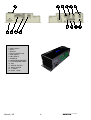
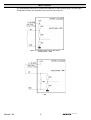
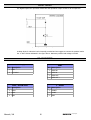
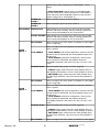
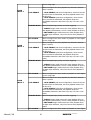
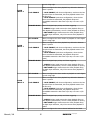
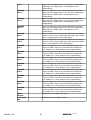
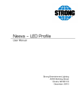
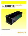
Manual / UK
1
DMXPEN
ControlBox
INDEX
Introduction .................................................................. page
3
Warnings ...................................................................... page
4
Description ................................................................... page
5
SetUp / Connections ...................................................... page
6
Technical Specification ................................................... page
7
Input Circuit .................................................................. page
9
Output Circuit ............................................................... page
10
PIN Assignment ............................................................ page
10
Device Configuration ..................................................... page
12
Remote Control ............................................................ page
17
Warranty ...................................................................... page
18
Maintenance / Cleaning ................................................. page
18
Manual / UK
2
DMXPEN
ControlBox
INTRODUCTION
Thanks to buy this DMXPEN series products.
A correct use of this product, will ensure a correct functionality, a long life and at the
same time will avoid product failure.
Please read this manual carefully and be sure to understand the information provide to
ensure a safe and reliable application, to learn a suitable knowledge of the product and
his necessary precaution before using it.
Manual / UK
3
DMXPEN
ControlBox
WARNINGS
1.
This manual describes the DMXPEN ControlBOX operating functions. The user must
operate the product according to the performance specifications described in the
operation manuals.
2.
While every effort has been made to ensure that the information on this manual is
accurate and complete, we would appreciate any errors or omissions submitted to
our attention.
3.
Maintenance, inspection, and replacement of parts must be performed only by
authorized personnel.
4.
We reserve the right to change the specifications of the hardware and software
described in this manuals at any time and without prior notice.
5.
Do not use DMXPEN ControlBOX with wet finger and do not place water on the
touch panel.
6.
After the package opening, please make this check:
• The received product correspond with the ordered one.
• No part are missing on the received product.
• The product is not damaged.
• Contact immediately a DMXPen distributor in case of fault.
Manual / UK
4
DMXPEN
ControlBox
DESCRIPTION
DMXPen ControlBOX device as the following features:
–
–
–
–
–
–
–
–
–
–
–
–
–
–
DMX512 Signal Recording and Playback
ArtNet Signal Recording and Playback
ArtNet - DMX Conversion
DMX - ArtNet Conversion
Recording and Playback remote control through ethrnet port
Playback remote control through MIDI port
Recording and Playback control through touch panel user interface
On board ROTARY SWITCH and graphic display allow system control and set up
8 digital / analog input
4 digital output
2 analog output
2 RS485 port
2 RS232 port
1 MicroSD card
Briefly the DMXPen products mission is record and carry easily: “Design your show, record and
bring with you”.
Why recording? The first goal of a professional light programmer is to select a light desk and
learn to use it in the best way, because this means freedom of expression and productivity.
The DMXPen products range improve this concept taking care of recording what the light
programmer realize whit his preferred equipment.
Why carry? Often the light programmer presence is not necessary during the show playback, so
he can realize the show and record it so the user has only the duty to activate his playback (i.e.
fair booth, shop, club, etc.)
Moreover doing this with a normal light desk, mean carry heavy or expensive equipment that
usually are not so familiar to the users (i.e. barman, custodian, etc.).
This is another issue improved from the DMXPen products because contains only the show
engine with a simple user interface at a very low cost.
Manual / UK
5
DMXPEN
ControlBox
SET UP/CONNECTION
Wire the needed line and the power supply on the provided removable connector (be
sure that the screw up is correct). Be sure to have the microSD card inserted on the
socket (the product is supplied with the microSD card inserted on the socket).
Note: the device do not has a main ON/OFF switch and is necessary remove power
supply to make maintenance.
Technical Specification
–
–
–
–
–
–
–
–
–
Features
Manual / UK
6
8
4
2
2
1
1
2
1
1
digital/analog INPUT
digital OUTPUT
analog OUTPUT
RS485
MIDI IN
MIDI OUT
RS232
micro SD Card
Ethernet Port
DMXPEN
ControlBox
Technical Specification
Dimension ( L x W x H )
200 x 160 x 88 mm
Weight
260 gr.
Material / finishing
Aluminium / Black Oxide
Degree protection
IP 30
Operating Relative Humidity : from 30% to 85% without condensation
Operating Temperature
-5°C + 50°C
DMX IN Connector
5 pole XLR Neutrik male
DMX OUT Connector
X5 pole XLR Neutrik female
Ethernet Connector
RJ45 Neutrik
Power Supply
12-24 VDC – 500 mA
DIGITAL INPUT
- NPN/PNP configurable
- 24 VDC INPUT max.
- 8 channel shared with analog INPUT
ANALOG INPUT
- 10 bits converter
- 10 VDC INPUT max.
- 8 channel shared with digital INPUT
DIGITAL OUTPUT
- 4 channel
- low RDSon (<0.015 Ohm) mosfet
- 24 VDC max.
- 20 A max. peak
- 4 A max. continuos
- current monitor shared with analog INPUT
- 2 channel
- 8 bits converter
- 10 VDC OUTPUT max.
- 100 mA OUTPUT max.
ANALOG OUTPUT
Manual / UK
RS485
- 2 Optocoupled full duplex channel
- 500 Mbps max. communication speed
- 1 channel shared with RS232
RS232
- 2 full duplex channel
- 500 Mbps max. communication speed
- 1 channel shared with RS485
MIDI
- 1 MIDI IN port
- 1 MIDI OUT port
MicroSD card
- 1 MicroSD card socket
- FAT16 file system
Ethernet
- IEEE 802.3 10Base – T Ethernet interface
Power supply
- 12-24 VDC
- 200-500 mA
standard reference
EN 55022, EN 61000-4-2, EN 61000-4-4, EN 61000-4-5,
EN 61000-4-6, EN 61000-4-11, EMC 89/336/CEE,
BT 73/23/CEE
7
DMXPEN
ControlBox
1
2
8
9
3
11
12
13
14
7
6
5
10
1. Rotary Switch
2. RS232
3. Ethernet
4. Slot for MicroSD card
5. DMX IN/OUT
6. MIDI IN/OUT
7. POWER IN
8. DIGITAL/ANALOG INPUT
9. I OUT MEASURE ENBLE
10. DAC
11. DIGITAL OUTPUT
12. INPUT CONFIG
13. 2° RS485
14. COM1 - COM2
Manual / UK
8
DMXPEN
ControlBox
4
INPUT CIRCUIT
The analog/digital inputs can be configured as NPN type or PNP type through the on board Input
Configuration Jumper. The equivalent input circuits for all 8 input are:
Figure 1: Equivalent Input Circuit with Input
Configuration = NPN
Figure 2: Equivalent Input Circuit with Input Configuration =
PNP
Manual / UK
9
DMXPEN
ControlBox
OUPUT CIRCUIT
The digital outputs are open drain mosfet and the equivalent output circuits for all 4 output are:
Figure 3: Equivalent Digital Output circuit
A clamp diode for inductive load is internally provided and we suggest to connect the positive load to
the +V OUT COM as indicated in the figure above. Maximum positive load voltage is 24VDC.
PIN ASSIGNMENT
Power Supply
MIDI
Pin Description
Pin Description
1
GND
1
MIDI IN+
2
12-24VDC
2
MIDI IN-
3
MIDI OUT-
4
MIDI OUT+
DMX – SCREW PLUG
2nd RS485
Pin Description
Pin Description
1
DMX+
1
RS485+
2
DMX-
2
RS485-
3
GND
3
GND
Manual / UK
10
DMXPEN
ControlBox
DIGITAL OUTPUT
DIGITAL / ANALOG INPUT
Pin Description
Pin Description
1
GND
1
+V IN COM
2
OUTPUT 1
2
INPUT 1
3
OUTPUT 2
3
INPUT 2
4
OUTPUT 3
4
INPUT 3
5
OUTPUT 4
5
INPUT 4
6
+V OUT COM
6
INPUT 5
7
INPUT 6
8
INPUT 7
9
INPUT 8
10
GND
ANALOG OUTPUT
RS232
Pin Description
Pin Description
1
GND
1
+5VDC
2
ANALOG OUTPUT 1
2
RS232-TX1
3
ANALOG OUTPUT 2
3
RS232-RX1
4
+12VDC
4
5
GND
6
7
8
RS232-TX2
9
RS232-RX2
XLR DMX INPUT
XLR DMX OUTPUT
Pin Description
Pin Description
1
GND
1
GND
2
DMX-
2
DMX-
3
DMX+
3
DMX+
Manual / UK
11
DMXPEN
ControlBox
DEVICE CONFIGURATION
DMXPen Control Box has an on board user interface provided to configure the device.
This user interface consist in a main page and a configuration menu.
Main Page
Display device activity that can be:
1.
ArtNet - DMX Conversion, where the ArtNet frame rate is also indicated (the arrow indicates
data flow from ETH port to DMX port)
Figure 4: ArtNet to DMX data
direction
2.
DMX - ArtNet Conversion, where the DMX frame rate is also indicated (the arrow indicates
data flow from DMX port to ArtNet port)
Figure 5: DMX to ArtNet data
direction
3.
4.
Show Playback, where the frame counter is also indicated
Show Recording, where the frame counter is also indicated
Configuration Menu
Menu Level 1 Menu Level 2
PLAYBACK
Description
PLAY START
Allow to select shows and start playback
PLAY STOP
Stop any playback running
PLAY MODE
Allow to configure the playback mode between these 2 options:
1. DMX+ARTNET (the show playback frames are transmitted
on both DMX and ArtNet port)
2. DMX ONLY (the show playback frames are transmitted on
DMX port only)
POWER ON
MODE
Allow to configure the power on behaviour between these 3
options:
1. NO SHOW (at power on ControlBOX perform ArtNet to DMX
or DMX to ArtNet conversion regarding the data flow setup. No
playback is activated before any user or I/O request)
2. LAST SHOW (at power on ControlBOX start playback of the
last show started before power off. This constrain ControlBOX
to store on each playback start action the show number on the
internal EEProm. Remember that this memory area can be
writed 10,000 times)
3. SELECTED SHOW (at power on ControlBOX starts once the
Manual / UK
12
DMXPEN
ControlBox
default show number configured on “P.ON SHOW 1” menu
option)
4. SELECTED SHOW 1+2 (at power on ControlBOX starts
once the default show number configured on “P.ON SHOW 1”
menu option and when completed execute on loop the show
number configured on “P.ON SHOW 2”)
RECORDING
POWER ON
SHOW 1
Allow to setup the power on show number 1
POWER ON
SHOW 2
Allow to setup the power on show number 2
DMX RECORD
Select DMX port as record source, ask for the show number
selection and starts recording. During recording operation the
frame counter was displayed on the on board LCD
ARTNET RECORD Select ArtNet port as record source, ask for the show number
selection and starts recording. During recording operation the
frame counter was displayed on the on board LCD
SET SHOW N.
SHOW
INPUT 1
Allow to configure the show number to playback on each digital
input 1 rising edge
Allow to configure the show playback loop behaviour between
these 2 options:
LOOP ENABLE
1. LOOP ENABLE (with these configuration, each time the last
recorded frame is transmitted, the show playback restart from
the first one)
2. LOOP DISABLE (with these configuration, when the last
frame recorded is transmitted, the playback stops and
ControlBOX transmit the last frame up to any new user or I/O
event)
TRIGGER MODE
Allows for digital input priority and show triggering
1. ALWAYS trigger mode causes the show playback firing on
each digital input activation, even if a show playback is running
2. END SHOW trigger mode causes the show playback firing
on digital input activation, only if the current show playback is
ended
SET SHOW N.
SHOW
INPUT 2
Allow to configure the show number to playback on each digital
input 2 rising edge
Allow to configure the show playback loop behaviour between
these 2 options:
LOOP ENABLE
1. LOOP ENABLE (with these configuration, each time the last
recorded frame is transmitted, the show playback restart from
the first one)
2. LOOP DISABLE (with these configuration, when the last
frame recorded is transmitted, the playback stops and
ControlBOX transmit the last frame up to any new user or I/O
event)
TRIGGER MODE
Allows for digital input priority and show triggering
1. ALWAYS trigger mode causes the show playback firing on
each digital input activation, even if a show playback is running
2. END SHOW trigger mode causes the show playback firing
on digital input activation, only if the current show playback is
ended
SET SHOW N.
Manual / UK
Allow to configure the show number to playback on each digital
13
DMXPEN
ControlBox
input 3 rising edge
SHOW
INPUT 3
Allow to configure the show playback loop behaviour between
these 2 options:
LOOP ENABLE
1. LOOP ENABLE (with these configuration, each time the last
recorded frame is transmitted, the show playback restart from
the first one)
2. LOOP DISABLE (with these configuration, when the last
frame recorded is transmitted, the playback stops and
ControlBOX transmit the last frame up to any new user or I/O
event)
TRIGGER MODE
Allows for digital input priority and show triggering
1. ALWAYS trigger mode causes the show playback firing on
each digital input activation, even if a show playback is running
2. END SHOW trigger mode causes the show playback firing
on digital input activation, only if the current show playback is
ended
SET SHOW N.
SHOW
INPUT 4
Allow to configure the show number to playback on each digital
input 4 rising edge
Allow to configure the show playback loop behaviour between
these 2 options:
LOOP ENABLE
1. LOOP ENABLE (with these configuration, each time the last
recorded frame is transmitted, the show playback restart from
the first one)
2. LOOP DISABLE (with these configuration, when the last
frame recorded is transmitted, the playback stops and
ControlBOX transmit the last frame up to any new user or I/O
event)
TRIGGER MODE
Allows for digital input priority and show triggering
1. ALWAYS trigger mode causes the show playback firing on
each digital input activation, even if a show playback is running
2. END SHOW trigger mode causes the show playback firing
on digital input activation, only if the current show playback is
ended
SET SHOW N.
SHOW
INPUT 5
Allow to configure the show number to playback on each digital
input 5 rising edge
Allow to configure the show playback loop behaviour between
these 2 options:
LOOP ENABLE
1. LOOP ENABLE (with these configuration, each time the last
recorded frame is transmitted, the show playback restart from
the first one)
2. LOOP DISABLE (with these configuration, when the last
frame recorded is transmitted, the playback stops and
ControlBOX transmit the last frame up to any new user or I/O
event)
TRIGGER MODE
Allows for digital input priority and show triggering
1. ALWAYS trigger mode causes the show playback firing on
each digital input activation, even if a show playback is running
2. END SHOW trigger mode causes the show playback firing
on digital input activation, only if the current show playback is
ended
SET SHOW N.
Manual / UK
Allow to configure the show number to playback on each digital
14
DMXPEN
ControlBox
input 6 rising edge
SHOW
INPUT 6
Allow to configure the show playback loop behaviour between
these 2 options:
LOOP ENABLE
1. LOOP ENABLE (with these configuration, each time the last
recorded frame is transmitted, the show playback restart from
the first one)
2. LOOP DISABLE (with these configuration, when the last
frame recorded is transmitted, the playback stops and
ControlBOX transmit the last frame up to any new user or I/O
event)
TRIGGER MODE
Allows for digital input priority and show triggering
1. ALWAYS trigger mode causes the show playback firing on
each digital input activation, even if a show playback is running
2. END SHOW trigger mode causes the show playback firing
on digital input activation, only if the current show playback is
ended
SET SHOW N.
SHOW
INPUT 7
Allow to configure the show number to playback on each digital
input 7 rising edge
Allow to configure the show playback loop behaviour between
these 2 options:
LOOP ENABLE
1. LOOP ENABLE (with these configuration, each time the last
recorded frame is transmitted, the show playback restart from
the first one)
2. LOOP DISABLE (with these configuration, when the last
frame recorded is transmitted, the playback stops and
ControlBOX transmit the last frame up to any new user or I/O
event)
TRIGGER MODE
Allows for digital input priority and show triggering
1. ALWAYS trigger mode causes the show playback firing on
each digital input activation, even if a show playback is running
2. END SHOW trigger mode causes the show playback firing
on digital input activation, only if the current show playback is
ended
SET SHOW N.
SHOW
INPUT 8
Allow to configure the show number to playback on each digital
input 8 rising edge
Allow to configure the show playback loop behaviour between
these 2 options:
LOOP ENABLE
1. LOOP ENABLE (with these configuration, each time the last
recorded frame is transmitted, the show playback restart from
the first one)
2. LOOP DISABLE (with these configuration, when the last
frame recorded is transmitted, the playback stops and
ControlBOX transmit the last frame up to any new user or I/O
event)
TRIGGER MODE
Allows for digital input priority and show triggering
1. ALWAYS trigger mode causes the show playback firing on
each digital input activation, even if a show playback is running
2. END SHOW trigger mode causes the show playback firing
on digital input activation, only if the current show playback is
ended
DMXADR
Manual / UK
Allow to configure the source channel address for the PWM
15
DMXPEN
ControlBox
Manual / UK
OUT 1
duty cycle of the digital output 1 from the current DMX frame
(DMX Input port, ArtNet port or show playback source
independently)
DMXADR
OUT 2
Allow to configure the source channel address for the PWM
duty cycle of the digital output 2 from the current DMX frame
(DMX Input port, ArtNet port or show playback source
independently)
DMXADR
OUT 3
Allow to configure the source channel address for the PWM
duty cycle of the digital output 3 from the current DMX frame
(DMX Input port, ArtNet port or show playback source
independently)
DMXADR
OUT 4
Allow to configure the source channel address for the PWM
duty cycle of the digital output 4 from the current DMX frame
(DMX Input port, ArtNet port or show playback source
independently)
DMXADR
DAC 1
Allow to configure the source channel address for the analog
output 1 from the current DMX frame (DMX Input port, ArtNet
port or show playback source independently)
DMXADR
DAC 2
Allow to configure the source channel address for the analog
output 2 from the current DMX frame (DMX Input port, ArtNet
port or show playback source independently)
DMXADR
STR 1
Allow to configure the source channel address for the serial
string command 1 from the current DMX frame (DMX Input
port, ArtNet port or show playback source independently)
DMXADR
STR 2
Allow to configure the source channel address for the serial
string command 2 from the current DMX frame (DMX Input
port, ArtNet port or show playback source independently)
DMXADR
STR 3
Allow to configure the source channel address for the serial
string command 3 from the current DMX frame (DMX Input
port, ArtNet port or show playback source independently)
DMXADR
STR 4
Allow to configure the source channel address for the serial
string command 4 from the current DMX frame (DMX Input
port, ArtNet port or show playback source independently)
DMXADR
STR 5
Allow to configure the source channel address for the serial
string command 5 from the current DMX frame (DMX Input
port, ArtNet port or show playback source independently)
DMXADR
STR 6
Allow to configure the source channel address for the serial
string command 6 from the current DMX frame (DMX Input
port, ArtNet port or show playback source independently)
DMXADR
STR 7
Allow to configure the source channel address for the serial
string command 7 from the current DMX frame (DMX Input
port, ArtNet port or show playback source independently)
DMXADR
STR 8
Allow to configure the source channel address for the serial
string command 8 from the current DMX frame (DMX Input
port, ArtNet port or show playback source independently)
INPUT
STATUS
Display the current digital input status
SOFTWARE
VER
Display the current software version
16
DMXPEN
ControlBox
REMOTE CONTROL
DMXPen ControlBOX is provided with the standard DMXPen engine that allow remote
control through MIDI interface or PenSuite software tools (PenSuite is a free software
tools available on the device micorSD card or on www.dmxpen.com web site in both PC
and MAC OS version).
Manual / UK
17
DMXPEN
ControlBox
WARRANTY
12 month
(according to D.L. n.24 2 february2002, directive 1999/44/CE of European Parliament)
MAINTENANCE / CLEANING
No special maintenance operation are required for DMXPEN ControlBOX.
Anyway remember to unplug the device from the power supply during maintenance and
cleaning operation.
Moreover we suggest to make a backup copy of the show file stored on the microSD card
using a PC connected or other card reader device.
Use only dry cleaning cloth to clean DMXPen ControlBOX. Do not use cleaning solvent or
washing powder.
Manual / UK
18
DMXPEN
ControlBox
www.dmxpen.com
www.ArtisticLicence.com
Designed by and Copyright
Artistic Licence (UK) Ltd.
www.esta.org
Manual / UK
19
DMXPEN
ControlBox