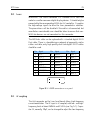
1
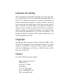
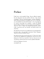
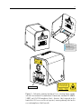
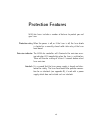
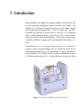
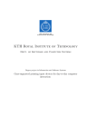
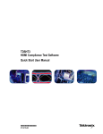
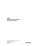
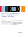
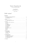
Cateye External Cavity Diode Laser
Model CEL002
Revision 1.00
Limitation of Liability
MOG Laboratories Pty Ltd (MOGLabs) does not assume any liability arising out of the use of the information contained within this
manual. This document may contain or reference information and
products protected by copyrights or patents and does not convey
any license under the patent rights of MOGLabs, nor the rights of
others. MOGLabs will not be liable for any defect in hardware or
software or loss or inadequacy of data of any kind, or for any direct,
indirect, incidental, or consequential damages in connection with or
arising out of the performance or use of any of its products. The
foregoing limitation of liability shall be equally applicable to any
service provided by MOGLabs.
Copyright
c MOG Laboratories Pty Ltd (MOGLabs) 2006 – 2014.
Copyright No part of this publication may be reproduced, stored in a retrieval
system, or transmitted, in any form or by any means, electronic,
mechanical, photocopying or otherwise, without the prior written
permission of MOGLabs.
Contact
For further information, please contact:
MOG Laboratories Pty Ltd
18 Boase St
Brunswick VIC 3056
AUSTRALIA
Tel: +61 3 9939 0677
Email: [email protected]
Web: www.moglabs.com
Preface
Diode lasers can be wonderful things: they are efficient, compact,
low cost, high power, low noise, tunable, and cover a large range of
wavelengths. They can also be obstreperous, sensitive, and temperamental, particularly external cavity diode lasers (ECDLs). With external cavity feedback and advanced electronics such as the MOGLabs
DLC external cavity diode laser controller, a simple $10 100 mW
AlGaAs diode can become a research-quality narrow-linewidth tunable laser. The CEL “cateye” laser described here provides a robust,
stable, acoustically inert, low linewidth and highly tunable laser
alternative.
We would like to thank the many people that have contributed their
hard work, ideas, and inspiration, in particular Daniel Thompson,
Sebastian Saliba and Michael Ventura.
We hope that you enjoy using the MOGLabs CEL. Please let us know
if you have any suggestions for improvement in the laser or in this
document, so that we can make life in the laser lab easier for all,
and check our website from time to time for updated information.
MOGLabs, Melbourne, Australia
www.moglabs.com
i
ii
Safety Precautions
Safe and effective use of this product is very important. Please read
the following laser safety information before attempting to operate
the laser. Also please note several specific and unusual cautionary notes before using MOGLabs lasers, in addition to the safety
precautions that are standard for any electronic equipment or for
laser-related instrumentation.
CAUTION – USE OF CONTROLS OR ADJUSTMENTS OR
PERFORMANCE OF PROCEDURES OTHER THAN THOSE
SPECIFIED HEREIN MAY RESULT IN HAZARDOUS
RADIATION EXPOSURE
Laser output from the CEL can be dangerous. Please ensure that
you implement the appropriate hazard minimisations for your environment, such as laser safety goggles, beam blocks, and door interlocks. MOGLabs takes no responsibility for safe configuration and
use of the laser. Please:
• Avoid direct exposure to the beam.
• Avoid looking directly into the beam.
• Note the safety labels (examples shown in figure below) and
heed their warnings.
• When the laser is switched on, there will be a short delay of
two seconds before the emission of laser radiation, mandated
by European laser safety regulations (IEC 60825-1).
• The STANDBY/RUN keyswitch must be turned to RUN before
the laser can be switched on. The laser will not operate if
iii
iv
the keyswitch is in the STANDBY position. The key cannot be
removed from the controller when it is in the clockwise (RUN)
position.
• To completely shut off power to the unit, turn the keyswitch
anti-clockwise (STANDBY position), switch the mains power
switch at rear of unit to OFF, and unplug the unit.
• When the STANDBY/RUN keyswitch is on STANDBY, there cannot be power to the laser diode, but power is still being supplied to the laser head for temperature control.
WARNING The internal circuit board and piezoelectric transducers are at
high voltage during operation. The unit should not be operated
with covers removed.
CAUTION Although the CEL is designed and priced with the expectation that the end-user can replace the diode and change the
alignment, some components are fragile. In particular the filter,
piezo actuator, and output coupler are very easily damaged.
Please take care of these items when working inside the laser.
The filter and output coupler are hard-coated and can be
cleaned but great care is needed as with any intracavity laser
optics.
NOTE MOGLabs products are designed for use in scientific research
laboratories. They should not be used for consumer or medical
applications.
Label identification
The International Electrotechnical Commission laser safety standard
IEC 60825-1:2007 mandates warning labels that provide information
on the wavelength and power of emitted laser radiation, and which
show the aperture where laser radiation is emitted. Figures 1 and 2
shows examples of these labels and their location on the CEL laser.
v
M
S o
Ma eriadl el nu
nu nu m
fac m be
ture ber: r:
d:
Co
de mpli
M viatio es
Bru OG ns puwith 21
E
rsu CF
ns La
an
A CD
R
wic bo
k V rato t to La 1040.10 JU 220 -00
IC rie ser No , an LY 33
0 3
30 s P
56 ty tice Nod 1040 201 211
, A Ltd,
02-0
.50 .11
1
US
,
ex
1
TR 18 B dated cept
ALI oa 24 Ju for
ne
A se
2007
St
Model number: ECD-004
Serial number: A42034011208-01
Manufactured: JULY 2012
Complies with 21 CFR 1040.10, and 1040.11 except for
deviations pursuant to Laser Notice No.50, dated 24 June 2007
MOG Laboratories Pty Ltd, 18 Boase St
Brunswick VIC 3056, AUSTRALIA
INVISIB
LE
AVOID LASER RADIA
EXP
TIO
CLASS OSURE TO BEA N
3B LAS
ER PRO M
DUCT
Waveleng
th
770 – 795
nm
Emission indicator
Max Pow
er
100 mW
IEC 6082
AS/NZS 5-1:2007
2211.5:20
06
INVISIBLE LASER RADIATION
AVOID EXPOSURE TO BEAM
CLASS 3B LASER PRODUCT
Wavelength
770 – 795 nm
Max Power
100 mW
IEC 60825-1:2007
AS/NZS 2211.5:2006
Figure 1: Schematic showing location of laser warning labels compliant with International Electrotechnical Commission standard IEC 608251:2007, and US FDA compliance label. Aperture label engraved on the
front of the CEL laser near the exit aperture; warning advisory label on the
rear and compliance label beneath.
vi
Model number: ECD-004
Serial number: A42034011208-01
Manufactured: JULY 2012
Complies with 21 CFR 1040.10, and 1040.11 except for
deviations pursuant to Laser Notice No.50, dated 24 June 2007
US FDA compliance
MOG Laboratories Pty Ltd, 18 Boase St
Brunswick VIC 3056, AUSTRALIA
AVOID EXPOSURE
VISIBLE AND INVISIBLE
LASER RADIATION IS
EMITTED FROM THIS APERTURE
INVISIBLE LASER RADIATION
AVOID EXPOSURE TO BEAM
CLASS 3B LASER PRODUCT
Wavelength
770 – 795 nm
Max Power
100 mW
Warning and advisory label
Class 3B
IEC 60825-1:2007
AS/NZS 2211.5:2006
INVISIBLE LASER RADIATION
AVOID EYE OR SKIN EXPOSURE TO
DIRECT OR SCATTERED RADIATION
CLASS 4 LASER PRODUCT
Wavelength
770 – 795 nm
Max Power
150 mW
Aperture label engraving
Warning and advisory label
Class 4
IEC 60825-1:2007
AS/NZS 2211.5:2006
Figure 2: Warning advisory and US FDA compliance labels.
Protection Features
MOGLabs lasers includes a number of features to protect you and
your laser.
Protection relay When the power is off, or if the laser is off, the laser diode
is shorted via a normally-closed solid-state relay at the laser
head board.
Emission indicator The MOGLabs controller will illuminate the emission warning indicator LED immediately when the laser is switched on.
There will then be a delay of at least 2 seconds before actual
laser emission.
Interlock It is assumed that the laser power supply is keyed and interlocked for safety. The laser head board also provides connection for an interlock (see appendix B), if used with a power
supply which does not include such an interlock.
vii
RoHS Certification of
Conformance
MOG Laboratories Pty Ltd certifies that the MOGLabs External Cavity Diode Laser does not fall under the scope defined in RoHS Directive 2002/95/EC, and is not subject to compliance, in accordance
with DIRECTIVE 2002/95/EC Out of Scope; Electronics related;
Intended application is for Monitoring and Control or Medical Instrumentation.
MOG Laboratories Pty Ltd makes no claims or inferences of the
compliance status of its products if used other than for their intended
purpose.
viii
Contents
Preface
i
Safety
iii
Protection Features
vii
RoHS Certification of Conformance
viii
1 Introduction
1.1 External cavity . . . . . . . . . .
1.2 Mode competition . . . . . . . . .
1.3 Piezo-electric frequency control
1.4 Temperature and current . . . . .
.
.
.
.
1
2
3
3
4
2 First light
2.1 Temperature . . . . . . . . . . . . . . . . . . . . . . . .
2.2 Current . . . . . . . . . . . . . . . . . . . . . . . . . . .
5
6
7
.
.
.
.
.
.
.
.
.
.
.
.
.
.
.
.
.
.
.
.
.
.
.
.
.
.
.
.
.
.
.
.
.
.
.
.
3 Alignment
3.1 Pre-alignment of lens tube and diode . . . . . .
3.2 Initial diode test . . . . . . . . . . . . . . . . . .
3.3 Orientation and polarisation of the output beam
3.4 Cateye reflector . . . . . . . . . . . . . . . . . . .
.
.
.
.
.
.
.
.
.
.
.
.
9
9
11
11
12
4 Operation
4.1 Wavelength . . . . . . . . . . . . . . . . . . . . . . . .
4.2 Scanning . . . . . . . . . . . . . . . . . . . . . . . . . .
4.3 External modulation . . . . . . . . . . . . . . . . . . .
15
15
16
18
A Specifications
A.1 RF response . . . . . . . . . . . . . . . . . . . . . . . .
19
21
ix
.
.
.
.
.
.
.
.
Contents
x
B Connector pinouts
B.1 Headboard . . . . . . . . . . . . . . . . . . . . . . . . .
B.2 Laser . . . . . . . . . . . . . . . . . . . . . . . . . . . .
B.3 RF coupling . . . . . . . . . . . . . . . . . . . . . . . .
23
23
25
25
References
28
1. Introduction
Semiconductor laser diodes are compact, efficient and low-cost, but
usually have poor wavelength control, linewidth and stability. The
addition of an external frequency-selective cavity allows control
of the operating wavelength over a few nm range, with sub-MHz
linewidth and stability. The MOGLabs CEL (see Fig. 1.1) is machined
from a solid aluminium block, so that the laser is stable, robust,
and insensitive to acoustic disturbances. The cavity is hermetically
sealed for additional suppression of environmental fluctuations and
drift.
The MOGLabs CEL is a “cat-eye” design (see Fig. 1.2), in which an
external cavity is formed between the rear reflecting surface of the
semiconductor diode, and a cat-eye reflector at several centimetres
from the diode [1–3]. Rather than the customary diffraction grating
of Littrow-configuration ECDLs, a high efficiency ultranarrow filter
Figure 1.1: Inside the MOGLabs CEL cateye laser.
1
Chapter 1. Introduction
2
is used to select a single external cavity mode. Without the need
for illuminating a large area of a grating for feedback, a cat-eye
retroreflector and partially transmitting output coupler can be used
to form the external cavity. The cateye reflector is inherently selfaligning, so that the laser is extremely insensitive to mechanical
disturbance, and also ensures high feedback coupling efficiency and
consequently narrow linewidth.
PZT
LENS
DIODE
FILTER
LENS
OC LENS
Figure 1.2: Schematic of a cateye external cavity diode laser (ECDL). The
external cavity, formed by the rear facet of the laser diode and the output
coupler, determines the laser frequency. One longitudinal cavity mode is
selected by an ultranarrow intracavity bandpass filter. A cateye reflector
is formed by the output coupler (OC) and intracavity lens, and the light is
recollimated by the extracavity output lens.
The output beam from a laser diode is collimated with a high numerical aperture (NA) lens and incident on the filter. The filter transmission wavelength depends on the rotation angle. Transmitted light is
back-reflected by the cateye lens/output-coupler combination which
efficiently couples light back into the laser diode. More details can
be found in the references [1–3].
1.1
External cavity
Semiconductor laser diodes normally have a high reflectivity rear
facet and a front facet with reflectivity of only a few percent. The
diode cavity is called the intrinsic or internal cavity. The external
cavity is formed by the cateye and the diode rear facet, and when
the external feedback is greater than that of the front facet, the ex-
1.2 Mode competition
3
ternal cavity determines the lasing wavelength. The external cavity
is typically around 40 mm long from rear facet of semiconductor to
output coupler, giving a cavity mode spacing (FSR) of c/2L = 3 to
4 GHz.
The laser diode and collimating lens are held rigidly in a focusing
tube. The filter is fixed to a bearing-mounted rotation assembly
with fine actuator screws to adjust the angle. The spring-loaded
screws operate in a push-pull arrangement which can be locked
against each other to further reduce the effects of mechanical vibration. Variation of the filter angle is used for coarse selection of the
wavelength, within the gain bandwidth of the laser diode.
1.2
Mode competition
As the wavelength is varied, competition between the frequency determined by the internal and external cavities, and the filter transmission window, leads to mode hops. From figure 1.3 it can be seen
that the net gain (combined product of semiconductor gain, filter
loss, internal and external cavity interference) can be very similar
at adjacent external cavity modes. A small change in the internal
cavity mode, or the filter angle, can lead to the overall gain being
greater at a mode adjacent to the mode in which the laser is oscillating, and the laser then hops to that higher-gain mode. See
Ref. [4] for a detailed discussion.
1.3
Piezo-electric frequency control
Small changes to the laser frequency are achieved by controlling
the external cavity length with a piezo electric actuator. For the
MOGLabs CEL, the output coupler is mounted to a multilayer piezoelectric “stack”. The cavity length variation is of order 10 nm per volt,
producing a frequency shift of 70 MHz/V with a range of 10 GHz for
150 V drive voltage. The bandwidth is limited by mechanical resonances, typically 25 kHz.
Chapter 1. Introduction
4
Diode cavity
Diode gain
External cavity
Filter
COMBINED
384.0
384.1
384.2
Frequency (THz)
384.3
384.4
Figure 1.3: Schematic representation for the various frequency-dependent
factors of an ECDL, adapted from Ref. [4], for wavelength λ = 780 nm and
external cavity length Lext = 15 mm.
1.4
Temperature and current
The laser frequency is also dependent on temperature and injection
current; the sensitivities are typically 3 MHz/µA and 30 GHz/K [5].
Thus, low-noise stable electronics, such as the MOGLabs DLC external cavity diode laser controller, are essential (see Ref. [6]) to
achieve sub-MHz linewidth and stability.
A critical aspect of an ECDL is temperature control of the cavity, since
the laser frequency depends on the cavity length and hence on the
thermal expansion coefficient of the cavity material [4]. The cavity
can be machined from materials with low thermal expansion coefficient but even then the passive stability is inadequate for research
applications. Active feedback of the cavity temperature combined
with cavity length control provide a flexible and stable approach.
The MOGLabs CEL uses a negative temperature coefficient (NTC)
thermistor to sense the cavity temperature and Peltier thermoelectric cooler (TEC) to heat and cool the cavity material.
2. First light
Initial installation of the laser is typically a matter of mounting it
to an optical table and connecting to a MOGLabs controller. The
laser can be mounted to posts using the M3 threaded holes on the
base, or by removing the cover and screwing directly to the optical
table using the M6x25 socket head cap screws provided. The hole
spacing also allows direct mounting to imperial tables for non-metric
countries (Burma, Liberia and the USA).
The laser includes a water cooling channel for laser operation at
unusually high or low temperatures, or in laboratories with high or
unstable air temperature. For most applications, water cooling is
not required; dissipation to the air and/or optical table is sufficient.
The performance of an external cavity diode laser is strongly dependent on the external environment, and in particular acoustic vibrations. Very small changes in the external cavity length have a
large effect on the laser frequency, typically 25 MHz per nanometre
length change. The monolithic block construction of the MOGLabs
CEL reduces the influence of vibrations on the cavity length, but some
elasticity remains. Acoustic disturbances in the air gap also affect
the frequency. Active feedback to the laser frequency reduces these
influences, but some simple measures to minimise coupling to environmental variations and vibration sources may be warranted. For
example, a surrounding box to reduce air movement and accidental
bumping of the laser; mounting the laser to a heavy support, and isolation from the optical table with an intermediary breadboard which
is separated from the main optical table with viscoelastic polymer
(e.g. SorbothaneTM ).
Once the laser is mounted appropriately, the laser can be switched
on. Please refer to the supplied test data for nominal temperature
and current settings, and in particular be aware of the maximum
current limit.
5
Chapter 2. First light
6
It is assumed that a MOGLabs DLC controller will be used to drive
the laser. If an alternative supply is used, note that +5 V must be
provided on pin 15 of the headboard connector to open the protective
relay. See section B.1 for connection details. Also please refer to
the laser test data for the maximum safe operating current.
2.1
Temperature
The preferred diode temperature will depend on the diode, the required wavelength, and the ambient room temperature. For example, typical AlGaAs diodes used for data storage applications (CD-R
burners) have a nominal wavelength of λ = 784 nm at 25◦ C, with
a dλ/dT slope of −0.3 nm/ ◦ C, implying an optimum temperature of
about 12◦ . Depending on the humidity, low temperatures may induce condensation on the diode and collimation lens. The filter will
determine the final wavelength, and the feedback is generally sufficient to “pull” the wavelength by ±5 nm, and thus in this example a
sensible set temperature would be about 17 to 18◦ C.
2.2 Current
Current
The output of semiconductor laser diodes follow a nominally linear
power vs. current relationship, once the current is above a devicespecific threshold (see Fig. 2.1). Initially the current should be set
above threshold, but well below the nominal maximum operating
current, until the laser is fully aligned.
140
Bare 150mW diode
780.243nm
Extracavity estimate
120
Power (mW)
2.2
7
100
80
60
40
20
0
0
20
40
60
80
100
120
Injection current (mA)
140
160
180
200
Figure 2.1: Sample laser diode power-current characteristic curves, with
and without an external cavity. The output for a diode with good antireflection coating is negligible. The steps show that for higher currents,
some of the light from the diode is not transmitted by the filter, typically
because the external cavity mode frequency is not perfectly aligned with
the filter transmission frequency.
8
Chapter 2. First light
3. Alignment
The cateye reflector arrangement is self-aligning, and should not
require adjustment. However, laser diodes have a finite lifetime, and
diode replacement may necessitate alignment of the internal optics,
in particular the diode collimation and cateye lenses.
For longer wavelength lasers, an infra-red upconversion card or CCD
camera can be very helpful. Common low-cost security cameras,
computer USB cameras, and home movie or still cameras are also
good options, although they often have infra red filters which may
need to be removed.
Diodes are very sensitive to electrostatic discharge. Please make
sure you are electrically grounded, ideally with a wrist ground strap.
If you do not have a proper wrist ground strap, at least be sure you
are not wearing woolen clothing, and touch something grounded from
time to time (e.g. a soldering iron tip, the earth of a power supply,
the MOGLabs DLC controller).
3.1
Pre-alignment of lens tube and diode
1. Insert the laser diode into the lens tube (see Fig. 3.1). If using
a lens tube with alignment screws, ensure that the V-notch in
the diode is aligned with one of the alignment screws.
2. Add the retaining threaded ring, and tighten gently, just enough
such that the diode does not move.
3. If using a lens tube with alignment adjustment screws, use the
5.6 mm retaining ring even for 9 mm diodes.
4. Approximately centre the diode using the alignment adjustment screws and two 0.9 mm hex keys.
5. Insert the collimation lens, taking care to ensure that the lens
9
Chapter 3. Alignment
10
Lens
Retaining
ring
5.6mm diode
9mm diode
Figure 3.1: Lens tube assembly, showing diode, lens, and mounting hardware. The same tube can be used for 5.6 mm and 9 mm diodes. Note that
your lens tube may have alignment adjustment screws.
Figure 3.2: Image showing collimation tubes.
does not contact the diode. Also ensure the lens is tight; if
not, use PTFE tape on the lens threads. Two layers of thick
tape (90 µm as used for gas plumbing) is good.
6. Mount the lens tube in a holder or mount that allows rotation
of the entire assembly around the long axis.
7. Apply power to the diode, above threshold but well below the
maximum permissible current.
8. Approximately focus at several metres distance. It may be
helpful to reflect it from a mirror and back so that you can
adjust the alignment and see the effect nearby. You should
adjust focus until you see a clean symmetric ellipse at this
3.2 Initial diode test
11
distance.
9. Rotate the collimation assembly and adjust the alignment screws
until the beam remains reasonably well on-axis.
10. Tighten the retaining ring (hard) and re-check that the diode
remains aligned.
11. Focus the collimation lens such that the laser focuses to a spot
at some significant distance, more than 4m. The laser stability
and modehop free range can be better if the laser output is
weakly converging [6].
3.2
Initial diode test
1. Inspect the beam profile for diffraction fringes. If the lens
has been screwed in too far and made contact with the diode
(particularly for 5.6 mm diodes), the lens can become scratched
or stressed, leading to poor performance. Fringes can be an
indication of such scratches (or an indication of a poor diode).
2. On the MOGLabs DLC controller, make sure DIP switch 4 (Bias)
is OFF, the span is set to zero (fully anti-clockwise), and the
frequency knob is at zero (middle of range; set the display
selector to Frequency and adjust to zero volts).
3. Measure the power/current (LI) curve for the bare collimated
diode. This provides a useful benchmark for comparison when
optimising the threshold lowering with feedback.
3.3
Orientation and polarisation of the output beam
The output from the diode is a widely diverging elliptical beam,
normally TE polarised; that is, with polarisation parallel to the short
(minor) axis of the ellipse. The filter performance is typically better
in p-polarisation; that is, with polarisation in the plane of reflection
Chapter 3. Alignment
12
Filter
E
From diode
θ
Figure 3.3: Orientation of the diode laser beam ellipse with respect to the
filter rotation, for TE polarised diode, oriented with p-plane polarisation.
from the filter. In that case, for the MOGLabs CEL, the polarisation
should be horizontal and the ellipse should be with long axis vertical.
Some diodes, particularly around 750 to 820 nm, are TM polarised,
with polarisation parallel to the long axis of the ellipse. For these
diodes, the ellipse should be horizontal.
The filter dependence on polarisation is weak and in most cases any
rotation of the diode will work acceptably well.
3.4
Cateye reflector
Light reflected from a cateye lens/mirror combination will be parallel
to the incident radiation, regardless of the incident angle. Thus the
cateye reflector is self-aligning: the light is always reflected back to
the diode, even if the beam is not well collimated. The effect relies
on the lens-mirror distance matching the focal length of the lens.
There are several methods for achieving optimum focus; probably the
easiest is to adjust the focus so as to minimise the lasing threshold.
Mount the diode collimation lens tube and cateye reflector assem-
3.4 Cateye reflector
13
35mm
Lens tube
Cateye
Recollimator
Figure 3.4: Arrangement of lens tube and cateye reflector for adjustment
of focus of cateye.
bly at about 35 mm apart, without filter (see Fig. 3.4). Set the diode
current just below threshold, and then adjust the cateye lens focus
until the output suddenly flashes brightly, indicating effective feedback which tends to lower the overall ECDL gain threshold. Repeat
until the minimum is obtained.
The sequence is as follows:
1. Mount the lens tube and cateye reflector about 35 mm apart.
2. Monitor the output beam on a piece of black card at a short
distance from the cateye assembly. It is helpful to recollimate
the output after the cateye; any lens can be used, at approximately the focal length of that lens from the output coupler.
Monitor the beam spot using a security camera or webcam.
3. Adjust the injection current to just below threshold.
4. Adjust the cateye lens focus until a bright flash (i.e. lasing) is
observed.
5. Iterate reduction of the injection current, following by focus of
the cateye, until the minimum threshold is achieved.
6. Reassemble the laser and adjust the filter angle to achieve the
desired wavelength.
14
Chapter 3. Alignment
7. If possible, scan the laser through an atomic resonance and
view the absorption on an oscilloscope. With current bias
disabled (DIP 4 on a MOGLabs controller) and full span, you
should see a reasonable fraction of the absorption spectrum,
with one or more mode-hops. A Fabry-Perot etalon or a fast
high-resolution wavemeter (MOGLabs MWM) can also be used
to optimise the mode-hop-free range.
8. Adjust the filter angle, and the injection current, to optimise
the scans so that you see the maximum number of repeats and
the deepest signals.
9. Check that the saturated absorption traces are clean. Noisy
spectra indicate multi-mode operation, or high linewidth, which
may be due to weak feedback. The lasing threshold is a good
diagnostic: lower threshold indicates better feedback and consequently lower linewidth.
A scanning Fabry-Perot or a MOGLabs MWM wavemeter is a
very useful diagnostic tool to check for single-mode operation.
10. Measure the laser output power as a function of diode injection
current, and plot the power/current response as in Fig. 2.1.
Compare against the original data provided with your laser
and if concerned about discrepancies, contact MOGLabs.
11. Switch the current bias (DIP switch 4) back on, and adjust the
bias to optimise the mode-hop-free scan range.
The laser should now be operating with mode-selected feedback
near the desired wavelength of the diode. The threshold current
should be significantly lower than without feedback (2 to 5 mA for
standard 780 nm diodes). Record the output power and threshold
characteristics for subsequent reference.
4. Operation
Normal operation of the laser is usually a matter of adjusting the
filter rotation angle to select the correct wavelength, and adjusting the piezo offset, diode injection current and bias to achieve the
maximum possible mode-hop free scan.
4.1
Wavelength
The primary control of wavelength is the filter rotation angle, which
can be adjusted while the laser is operational. A wavemeter [7],
high-resolution spectrometer, or similar is almost essential, although
with patience it is possible to find an atomic reference by carefully
adjusting the filter angle while scanning the laser.
The filter transmission wavelength shifts with rotation according to
s
sin(θ) 2
λ(θ) = λ0 1 −
(4.1.1)
neff
where θ is the angle of incidence, λ0 is the filter wavelength at normal incidence and neff = 2.13 for p-polarization. The sensitivity to
rotation of the fine tangential wavelength adjustment screw (labelled
λ in figure) is about 0.5 nm per turn.
Set the laser current so that the output power is sufficient, taking
care to ensure that the internal cavity power is below the maximum
rated for the diode (see Fig. 2.1). Then change the filter angle to
adjust the wavelength. The laser will hop between external cavity
modes, as the wavelength is adjusted, through cycles of dim and
bright output. Adjust the angle to one of the bright modes nearest
the optimum wavelength, and then adjust the laser current and the
piezo voltage to achieve the exact wavelength required.
15
Chapter 4. Operation
16
Figure 4.1: Sketch of the MOGLabs CEL, showing the filter rotation adjustment screw, labelled λ.
4.2
Scanning
The external cavity length is controlled by piezo actuators moving
the output coupler. The cavity length increases with increasing voltage on the piezos, thus decreasing the laser frequency. For a large
frequency change, the laser will usually hop to a neighbouring cavity
mode (see Fig. 4.2).
The continuous scan range (free of mode hops) can be optimised by
careful adjustment of the injection current, which affects the refractive index of the diode semiconductor and hence the frequency of the
cavity mode.
This shift of cavity mode frequency allows for compensation of the
mismatch of tuning responses. The diode injection current can be
4.2 Scanning
17
Relative Gain
1
0
-200
-100
0
100
200
Frequency (GHz)
Figure 4.2: Combined gain for an external cavity diode laser, including the
internal and external modes, the diode laser gain, and the filter absorption.
The predominant feature is the frequency selectivity of the filter, and the
smaller peaks are the external cavity modes (see Fig. 1.3). A small relative
shift of the external cavity mode relative to the filter frequency will cause
the laser to jump to another external cavity mode where the net gain is
higher.
“automatically” adjusted as the laser frequency is changed, using a
“feed-forward” or current bias which changes as the piezo voltage
is changed. Feed-forward current bias adjustment is a feature of
MOGLabs DLC controllers. Adjustment is straightforward. The laser
frequency is scanned (with a downward ramp voltage to the piezo),
and the current bias control is adjusted so that the current is also
ramping downward, until the maximum mode-hop-free scan range is
observed. Small changes to the injection current optimise the scan
range near the nominal centre frequency.
Chapter 4. Operation
18
4.3
External modulation
The laser diode injection current can be modulated directly, or via
the SMA RF input on the laser headboard (see section B.3). The
combined modulation bandwidth extends from DC to about 2.5 GHz,
provided the standard connection from headboard to diode is replaced with a suitable coaxial cable. Even higher frequencies can
be used with addition of an appropriate microwave bias-tee such as
the Minicircuits ZFBT-6G+, between the laser headboard and the
diode.
Direct modulation is commonly used for frequency stabilisation, e.g.
the frequency modulation sideband method [8, 9], Pound-DreverHall [10], and also for offset locking schemes [11, 12]. Microwave
modulation is often used for two-frequency pumping of alkali atoms,
for example to access both a laser cooling transition and a repump
to prevent trapping in dark states [4, 13, 14].
The modulation efficiency can be enhanced by matching the external
cavity length to the modulation frequency. That is, set the cavity
length L = c/2Ω where Ω is the modulation frequency. The cavity
length can be adjusted slightly by sliding the collimation tube in the
monolithic block. For example, to access the 87 Rb hyperfine ground
states, separated by 6.8 GHz, the cavity length could be 2.2 cm and
the modulation at 6.8 GHz, or 4.4 cm with modulation at 3.4 GHz so
that the two sidebands are used and the carrier is off-resonant.
A. Specifications
Parameter
Specification
Wavelength/frequency
50 mW standard. Up to 150 mW output
780 nm
power available.
Please contact MOGLabs for availability.
369.5 – 1120 nm
Linewidth
Typically < 150 kHz
RF modulation
160 kHz – 2.5 GHz
Filter
0.3 nm bandpass
Tuning range
Typically 10 nm for single diode
Sweep/scan
Scan range
10 GHz
Mode-hop free
10 GHz
Piezo stack
3 µm @ 150 V, 50 nF
Cavity length
35 mm
Optical
Beam
3 mm × 1 mm (1/e2 ) typical
Polarisation
Vertical linear 100:1 typical
(can be rotated)
19
Appendix A. Specifications
20
Parameter
Specification
Thermal
TEC
±14.5 V 3.3 A Q = 23 W standard
Sensor
NTC 10 kΩ standard; AD590, 592 optional
Stability at base
±1 mK (controller dependent)
Cooling
Optional: 4 mm diam quick-fit water cooling
connections
Electronics
Indicator
Diode short-circuit relay; cover interlock
connection; reverse diode
Laser ON/OFF (LED)
input
160 kHz – 2.5 GHz bias tee, to DC optional
Protection
RF
Connector
MOGLabs Diode Laser Controller single ca-
ble connect
Mechanical & power
Dimensions
108 × 70 × 83 mm (L×W×H), 1 kg
Beam height
54.5 mm
Shipping
420 × 360 × 260 mm (L×W×H), 3.1 kg
A.1 RF response
A.1
RF
21
response
The laser includes an RF bias tee, with typical frequency response
shown below. By default, the connection to the laser diode does not
provide the full bandwidth of the bias tee. A small circuit board,
for RF connection to the diode, is available from MOGLabs; please
contact us for further details if required.
Ref -20 dBm
TG
* Att
-30 dBm
50 dB
* RBW 30 kHz
* VBW 10 MHz
SWT 17 s
-20
-25
-30
-35
-40
-45
-50
-55
-60
-65
-70
Center 1.5 GHz
300 MHz/
Span 3 GHz
Figure A.1: RF response, SMA input on laser headboard to diode SMA
output.
22
Appendix A. Specifications
B. Connector pinouts
B.1
Headboard
The laser head interface board provides connection breakout to the
laser diode, TEC, sensor, piezo actuators, and laser head interlock.
It also includes a solid-state protection relay and passive protection
filters, a laser-on LED indicator, and an SMA connection for direct
diode current modulation. The connections are made with Hirose
DF59 “swing-lock” wire-to-board connectors.
For high bandwidth RF modulation the diode should be directly soldered to a special interconnect assembly available from MOGLabs.
No provision is made for optical power control or measurement for
diodes that have an internal photodiode.
Figure B.1: MOGLabs CEL laser head board showing connectors for laser
diode, piezo actuator, temperature sensors, TEC and head enclosure interlock.
23
Chassis Earth
Mount Hole
Single 5
Single 6
Single 3
Single 4
Single 1
Single 2
Pair 6
Pair 6
P6 Shield
P0/5 Shield
Pair 5
Pair 5
Pair 0
Pair 0
P1/3 Shield
Pair 3
Pair 3
Pair 1
Pair 1
P2/4 Shield
Pair 4
Pair 4
Pair 2
Pair 2
Laser Laser +
14
15
Relay Relay +
4k99
R2
Active sensor Active sensor +
6
7
8
16
Shield
Thermistor +
Thermistor Shield
Stack Piezo +
Stack Piezo -
20
21
19
Disc Piezo +
Disc Piezo -
17
18
24
23
22
Shield
11
12
13
Shield
3
Peltier Peltier +
9
10
4
5
1
2
P5v
RF Laser Current Input
Female SMA
Sig
4
3
2
1
R1
390R
P5v
R5
499R
U1B
U1A
SMA - 5P
Gnd
P1
P5v
NC
NC
2
1
5
6
7
8
HD4
R3
10k0
C4
D2
Flying leads
P5v
250V 10nF
DNI
Laser Interlock
Lid posiiton interlock
Voltage Free contact
that closes when box
in posiiton
LED
100uH
L1
43R
R4
D1
3
2
1
SMA - 5P
Gnd
Sig
P3
HD1
Laser
RF high bandwidth
connection to diode
Gnd
24
Appendix B. Connector pinouts
Figure B.2: CEL headboard schematic. The RF modulation low-pass cutoff
frequency is determined by C4 and the diode impedance (∼ 50Ω).
B.2 Laser
B.2
25
Laser
WARNING: The LASER connector is a standard DVI-D Dual Link
socket as used for consumer digital display devices. It should only be
connected to the corresponding MOGLabs DLC controller. It supplies
the high-voltage signals to drive the laser piezoelectric actuators.
The piezo drivers will be disabled if the cable is disconnected, but
nevertheless considerable care should be taken to ensure that nonMOGLabs devices are not connected via this connector.
The MOGLabs cable can be replaced with a standard digital DVI-D
Dual cable. There is a bewildering assortment of apparently similar
cables available; only high quality dual-link digital DVI-D cables
should be used.
Pin
1
2
3
4
5
6
7
8
Signal
TEC –
TEC +
Shield
TEC –
TEC +
AD590/592 –
AD590/592 +
Pin
9
10
11
12
13
14
15
16
Signal
DIODE –
DIODE +
Shield
DIODE –
DIODE +
Relay GND
Relay +5V
Interlock +5V
1
8
17
24
Pin
17
18
19
20
21
22
23
24
Signal
DISC +
DISC –
Shield
STACK +
STACK –
NTC –
NTC +
Figure B.3: LASER connector on rear panel.
B.3
RF
coupling
The SMA connector on the laser head board allows high-frequency
current modulation. The RF input is AC coupled, with low- and highfrequency limits of about 160 kHz and 2.5 GHz (see Fig. A.1). Capacitor C4, normally 10 pF, can be changed to adjust the low-frequency
26
Appendix B. Connector pinouts
cutoff. For higher bandwidths, use an external bias-tee such as the
Minicircuits ZFBT-6G+ between the head board and the diode.
The input sensitivity depends on the diode impedance, typically
about 50 Ω. Thus a 0 dBm signal corresponds to about 0.2 V and
a current of around 4 mA at the diode. That is, the current sensitivity is approximately 20 mA/V.
WARNING: The RF input is a direct connection to the laser diode.
Excessive power can destroy the diode. It is separated from the
head board relay by an inductor, and thus the relay does not provide
protection from high frequency signals.
Bibliography
[1] Daniel J. Thompson and Robert E. Scholten. Narrow linewidth
tunable external cavity diode laser using wide bandwidth filter.
Review of Scientific Instruments, 83(2):–, 2012. 1, 2
[2] X. Baillard, A. Gauguet, S. Bize, P. Lemonde, Ph. Laurent,
A. Clairon, and P. Rosenbusch. Interference-filter-stabilized
external-cavity diode lasers. Opt. Communic., 266:609, 2006.
1, 2
[3] M. Gilowski, Ch. Schubert, M. Zaiser, W. Herr, T. WÃijbbena,
T. Wendrich, T. MÃijller, E.M. Rasel, and W. Ertmer. Narrow bandwidth interference filter-stabilized diode laser systems
for the manipulation of neutral atoms. Optics Communications,
280(2):443 – 447, 2007. 1, 2
[4] S. D. Saliba, M. Junker, L. D. Turner, and R. E. Scholten. Mode
stability of external cavity diode lasers. Appl. Opt., 48(35):6692,
2009. 3, 4, 18
[5] H. Talvitie, A. Pietil¨
ainen, H. Ludvigsen, and E. Ikonen. Passive
frequency and intensity stabilization of extended–cavity diode
lasers. Rev. Sci. Inst., 68(1):1, 1997. 4
[6] S. D. Saliba and R. E. Scholten. Linewidths below 100 khz with
external cavity diode lasers. Appl. Opt., 48(36):6961, 2009. 4,
11
[7] P. J. Fox, R. E. Scholten, M. R. Walkiewicz, and R. E. Drullinger.
A reliable, compact, and low-cost michelson wavemeter for laser
wavelength measurement. Am. J. Phys., 67(7):624–630, 1999. 15
[8] S. C. Bell, D. M. Heywood, J. D. White, and R. E. Scholten.
Laser frequency offset locking using electromagnetically induced transparency. Appl. Phys. Lett., 90:171120, 2007. 18
27
[9] G. C. Bjorklund.
Frequency-modulation spectroscopy: a
new method for measuring weak absorptions and dispersions.
Opt. Lett., 5:15, 1980. 18
[10] R. W. P. Drever, J. L. Hall, F. V. Kowalski, J. Hough, G. M.
Ford, A. J. Munley, and H. Ward. Laser phase and frequency
stabilization using an optical resonator. Appl. Phys. B, 31:97–
105, 1983. 18
[11] M. Zhu and J. L. Hall. Stabilization of optical phase/frequency
of a laser system: application to a commercial dye laser with
an external stabilizer. J. Opt. Soc. Am. B, 10:802, 1993. 18
[12] M. Prevedelli, T. Freegarde, and T. W. H¨
ansch. Phase locking
of grating-tuned diode lasers. Appl. Phys. B, 60:241, 1995. 18
[13] P. Feng and T. Walker. Inexpensive diode laser microwave modulation for atom trapping. Am. J. Phys., 63(10):905–908, 1995.
18
[14] C. J. Myatt, N. R. Newbury, and C. E. Wieman. Simplified atom
trap by using direct microwave modulation of a diode laser.
Opt. Lett., 18(8):649–651, 1993. 18
28
MOG Laboratories Pty Ltd
18 Boase St, Brunswick VIC 3056, Australia
Tel: +61 3 9939 0677
[email protected]
c 2010 – 2014
Product specifications and descriptions in this document are subject to change without notice.