1
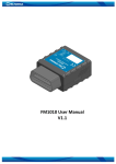
Agile RF Synthesizer & AOM driver
ARF021/ARF421, XRF021/XRF421
Revision 0.0.1
Limitation of Liability
MOG Laboratories Pty Ltd (MOGLabs) does not assume any liability arising out of the use of the information contained within this
manual. This document may contain or reference information and
products protected by copyrights or patents and does not convey
any license under the patent rights of MOGLabs, nor the rights of
others. MOGLabs will not be liable for any defect in hardware or
software or loss or inadequacy of data of any kind, or for any direct,
indirect, incidental, or consequential damages in connections with
or arising out of the performance or use of any of its products. The
foregoing limitation of liability shall be equally applicable to any
service provided by MOGLabs.
Copyright
c MOG Laboratories Pty Ltd (MOGLabs) 2015. No part
Copyright of this publication may be reproduced, stored in a retrieval system,
or transmitted, in any form or by any means, electronic, mechanical,
photocopying or otherwise, without the prior written permission of
MOGLabs.
Contact
For further information, please contact:
MOG Laboratories P/L
18 Boase St
Brunswick VIC 3056
AUSTRALIA
+61 3 9939 0677
[email protected]
www.moglabs.com
MOGLabs USA LLC
419 14th St
Huntingdon PA 16652
USA
+1 814 251 4363
[email protected]
www.moglabsusa.com
MOGLabs Europe
Goethepark 9
10627 Berlin
Germany
+49 30 21 960 959
[email protected]
Preface
Acousto-optic modulators (AOMs) are an integral part of many laserbased experiments. They are used for frequency shifting, amplitude
modulation, and laser frequency stabilisation. Many experiments require very simple control of the RF frequency and power, but others
require sophisticated sequences. The MOGLabs ARF/XRF agile RF
synthesizer provides such complexity with a user-friendly interface.
The extraordinary capabilities of the ARF/XRF have not previously
been available from any single supplier, let alone in a single unit.
Two channels, with direct output of up to 4 W per channel. Wide
frequency range of 20 to 400 MHz. Arbitrary frequency, amplitude
and phase with high resolution. Analogue modulation of each channel, in frequency, amplitude, and/or phase, with 10 MHz bandwidth.
Ergonomic front-panel controls, and ethernet/USB interface. Tablemode operation to define complex time-dependent waveform output.
All in one box which connects directly to AC mains power and to
your AOMs. As you delve into this manual you will uncover more and
more capability, but the powerful FPGA at the heart of the ARF/XRF
allows software improvements to add new features, so please check
the MOGLabs website for updates, example code, and assistance.
We hope that you enjoy using the ARF/XRF, and please let us know
if you have any suggestions for improvement in the ARF/XRF or in
this document, so that we can make life in the lab better for all.
MOGLabs, Melbourne, Australia
www.moglabs.com
i
ii
Safety Precautions
Safe and effective use of this product is very important. Please read
the following safety information before attempting to operate. Also
please note several specific and unusual cautionary notes before
using the MOGLabs ARF/XRF, in addition to the safety precautions
that are standard for any electronic equipment.
CAUTION To ensure correct cooling airflow, the unit should not be operated with cover removed.
WARNING High voltages are exposed internally, particularly around the
mains power inlet and internal power supply unit. The unit
should not be operated with cover removed.
NOTE The MOGLabs ARF/XRF is designed for use in scientific research laboratories. It should not be used for consumer or
medical applications.
iii
Protection Features
The MOGLabs ARF/XRF includes a number of features to protect you
and your device.
Open/short circuit Each RF output should be connected to a 50 Ω load. The
ARF/XRF will disable the each high-power RF output if not
connected or if a short-circuit is detected.
Reflected power The RF reflected power and VSWR (voltage standing wave
ratio) are monitored and RF output is disabled if either exceeds
their safe limit settings.
Mains filter Protection against mains transients.
Temperature Several temperature sensors control the fan and shutdown if
the temperature exceeds a safe limit.
iv
Contents
Preface
i
Safety Precautions
iii
Protection Features
iv
1 Introduction
1.1 Operating modes . . . . . . . . . . . . . . . . . . . . .
1.2 Table timing . . . . . . . . . . . . . . . . . . . . . . . .
1.3 RF on/off control . . . . . . . . . . . . . . . . . . . . .
1
2
4
4
2 Connections and controls
2.1 Front panel controls . . . . . . . . . . . . . . . . . . .
2.2 Front panel display/monitor . . . . . . . . . . . . . . .
2.3 Rear panel controls and connections . . . . . . . . . .
5
5
5
6
3 Communications
3.1 TCP/IP . . . . . . . . . . . . . . . . . . . . . . . . . . .
3.2 USB . . . . . . . . . . . . . . . . . . . . . . . . . . . .
9
9
11
4 Programming
4.1 python example . . . . . . . . . . . . . . . . . . . . . .
13
13
A Specifications
17
B Command language
B.1 Primary RF control
B.2 Complex functions
B.3 Modulation control
B.4 General functions .
B.5 Display functions .
19
19
20
21
21
22
.
.
.
.
.
.
.
.
.
.
.
.
.
.
.
.
.
.
.
.
v
.
.
.
.
.
.
.
.
.
.
.
.
.
.
.
.
.
.
.
.
.
.
.
.
.
.
.
.
.
.
.
.
.
.
.
.
.
.
.
.
.
.
.
.
.
.
.
.
.
.
.
.
.
.
.
.
.
.
.
.
.
.
.
.
.
.
.
.
.
.
.
.
.
.
.
.
.
.
.
.
vi
Contents
B.6 Auxilliary measurements . . . . . . . . . . . . . . . . .
B.7 Configuration settings . . . . . . . . . . . . . . . . . .
22
23
C Ugrading firmware
25
D Connector pinouts
D.1 IO connector . . . . . . . . . . . . . . . . . . . . . . . .
D.2 High-speed digital . . . . . . . . . . . . . . . . . . . .
27
27
28
References
29
1. Introduction
The MOGLabs ARF/XRF consists of two independent AD9910 direct
digital synthesizer (DDS) sources, each with 4 W amplifier. The frequency, amplitude and phase of each output is software-controlled
via a microcontroller and FPGA (field programmable gate array). The
frequency, amplitude and phase can be defined via front-panel control knobs, or via ethernet or USB. The RF parameters can be defined
in a lookup table (loaded via ethernet or USB) to enable complex sequences with very fast transitions.
The block diagram below shows the key components of the ARF/XRF.
The RF signal output from each (DDS) is low-pass filtered, preamplified, and then further amplified with a GaN hybrid high-power
Front Panel Display & Control
RF on/off
DDS + RF
RF OUT
FPGA
Ethernet
10/100
Micro
controller
USB
AD9910 DDS
LP filter
RF amplifier
Power detector
RAM table
memory
A/D
(2 per channel)
7-pole filters
10MHz
External
Clock
MOD IN
DAC
Output
Local
Oscillator
1
2
Chapter 1. Introduction
output stage (ARF421/XRF421 only). The RF signals are monitored to
check output power and to measure the reflection (VSWR).
The DDS chips are controlled by the FPGA. A microcontroller provides
external interface with TCP/IP and USB communications, and controls
the front-panel display, rotary encoders (knobs) and push-buttons.
The device allows analogue modulation through two analogue-todigital converters (ADC) with anti-aliasing filters. When modulation
is configured, the FPGA periodically reads the digital value of the
modulation signal and uses that value to reprogram the DDS frequency, power and/or phase.
The ARF/XRF includes memory for storing complex waveform sequences, where each step in the sequence can include frequency,
power, phase, time delay, and more complex definitions of ramps
and other time-dependent functions. Complex capabilities can be
accessed via either TCP/IP or USB communications. See Chapter 3
for information on communications options and setup.
Once communications are established, the ARF/XRF can be controlled
with simple text commands. The commands can be very basic, for
example to define the frequency or power, or they can define complex
dynamic sequences. Chapter 4 describes some example python code
for communicating with the device and for establishing a sequence,
and Appendix B provides a summary of the available commands.
1.1
Operating modes
The ARF/XRF can be used at varying levels of complexity, defined
in terms of operating modes. In normal mode, the ARF/XRF acts as
a simple single-frequency high-power RF source, controlled by the
front panel or computer commands.
In table mode, the RF output is determined by a table of commands
preloaded into internal look-up tables and stepped through automatically on the basis of pre-defined delays, in combination with
1.1 Operating modes
3
external hardware or software triggers.
Within each of the normal and table modes, there are sub-modes
with different levels of complexity and performance. To understand
these it is necessary to first explain some aspects of the DDS devices.
SIF and PIF – Serial and Parallel Interface: The DDS can be configured via serial (SIF) or parallel (PIF) interface. SIF is slower but
allows complete access to all DDS functions. PIF is faster but with
limited control.
DDS internal functions: Each DDS can be programmed via SIF, for
example to set a single-tone, with frequency, amplitude and phase,
or for more complex functions such as to automatically ramp the
RF parameters, and there is internal RAM for DDS-generated tablemode sequencing. Direct programming of each DDS is not covered
within this user manual. They are complex and direct access is not
necessary for most users, but full details are available in the AD9910
datasheet.
1.1.1
Normal mode
In normal mode, each DDS is configured by the microprocessor via
SIF. The power and frequency of each output can be individually
adjusted with the front-panel control knobs, or with computer commands via ethernet or USB interface. The RF output for each channel
can be activated by the front-panel on/off push-buttons or computer
commands, and the status of each is apparent from the adjacent LED
indicators and the front-panel display. Note that in-built protection
disables the RF if a fault is detected, for example open circuit (no
device connected), short-circuit, or if the reflected power is too high
(high VSWR).
Advanced options within normal mode include the ability to directly
access the DDS registers, for setting the VCO (voltage controlled
oscillator), or to enable DDS-ramps and DDS-RAM modes. Please
refer to the AD9910 datasheet for more information.
4
Chapter 1. Introduction
In normal single-frequency mode, the RF parameters can also be
controlled by the external analogue modulation inputs.
1.1.2
Table mode
In table mode, the RF parameters are automatically sequenced by
the FPGA according to a table of values pre-loaded by the microprocessor. Configuration of each DDS can be via SIF or PIF (XRFx21
only). The table entries are defined by simple text commands from
the host computer. Table entries can define RF frequency, amplitude and phase. They can also define delay times, wait-for-trigger
(hardware or software), and more complex functions such as ramps.
The minimum duration of a table entry is 1 µs.
1.1.3 XRFx21 advanced
The XRFx21 models provide higher speed using SIF and PIF, and
increase the size of the table to hundreds of thousands of entries.
Timing resolution improves to 32 ns per table entry.
1.2
Table timing
Each table entry has an associated duration value, which can be a
fixed time, or a wait-for-trigger. Stepping through the table can then
be controlled from the external dedicated TTL input for that channel.
1.3
RF
on/off control
Is very complicated.
2. Connections and controls
2.1
Front panel controls
Agile RF Synthesizer
CHANNEL 1
STATUS
CHANNEL 2
CHAN 1
STATUS
STATUS
CHAN 2
POWER
FREQUENCY
POWER
OFF
ON
FREQUENCY
POWER
OFF
ON
FREQUENCY
The frequency encoder can be used to adjust the frequency for each
RF channel, when operating in manual mode. The encoder is speedsensitive so to make small changes, rotate the knob slowly. The
current frequency is displayed on the LCD display.
POWER
Similarly, the output power can be adjusted for each channel.
OFF/ON
The RF output can be enabled or supressed with the push-button
off/on switch for each channel.
STATUS
Each channel has a multi-colour status LED indicator.
2.2
Front panel display/monitor
The LCD display shows key information including frequency and
power for each channel, and ethernet IP address and port number.
The push-buttons and LEDs adjacent to the display have limited
functionality at present, with plans for future enhancement:
← Activate firmware upgrade if held down during startup.
OK + ↓ Hold both down to reset.
5
6
Chapter 2. Connections and controls
2.3
Rear panel controls and connections
MOD IN
RF OUT
RF OUT 1
MON 1
90–264Vac 47–63Hz
RF OUT 2
FREQ 1
FREQ 2
MON 2
AMP 1
AMP 2
CLK IN
MOD OUT
SN:
IEC power in/out
The ARFx21 is compatible with all standard AC power systems, from
90 to 264 V and 47 to 63 Hz. The maximum current is about 1 A.
Fan
The ARFx21 has three temperature-controlled fans directing air flow
over the RF power amplifiers, the FPGA and through the rear vent.
RF OUT
There are two outputs for each RF channel, with SMA connectors
and 50 Ω impedance. The high-power outputs are labelled RF OUT
1,2. The MON are separately buffered signals at −20 dBc relative
to each main output respectively.
MOD IN
Each RF channel has two associated analogue inputs, nominally for
frequency and amplitude modulation. These inputs can be reconfigured for frequency, amplitude, phase, or sampling for DSP applications. The modulation inputs can be used for laser noise-eater or
frequency stabilisation applications. The bandwidth of each input is
10 MHz, with 14-bit 65 MHz sampling. The inputs are anti-aliased
with 7th -order filters.
CLK IN
The ARFx21 uses a high stability OCX crystal clock, but can also be
synchronised to an external clock (5 MHz to 1 GHz).
MOD OUT
The ARFx21 provides three analogue outputs with 14-bit resolution
and 1 MHz output. One is available at the MOD OUT SMA connector;
the other two can be accessed from the DB15 connector.
2.3 Rear panel controls and connections
7
DB15
The DB15 connector provides fast TTL inputs for quickly supressing
the RF output, and for hardware triggering of sequences. Additional
digital outputs can be used for controlling experimental devices such
as shutters. Two general-purpose analogue outputs, similar to MOD
OUT, are also available.
RJ45/USB-A
Ethernet (TCP/IP 10/100 Mb/s) and USB communications jacks.
8
Chapter 2. Connections and controls
3. Communications
The ARFx21 can be connected by USB or ethernet (TCP/IP). From the
user and device perspective, the two are equivalent.
3.1
TCP/IP
When ethernet is connected, the ARFx21 will attempt to obtain an IP
address by DHCP. If DHCP fails, an internally defined address will
be used. In both cases, the address will be shown on the device
display, something like:
10.1.1.190/7802
The dotted-quad number (10.1.1.190) is the device IP address; you
can type that into the address bar on your web browser and you will
see a simple webpage for the device (via the standard http port 80).
The web interface is minimal, and is primarily for uploading new
firmware.
The second number (7802) is the TCP/IP port number. This port
provides full access to device functionality. It is through this port that
your control software should access the device. Simple commands
can be sent to the device using the telnet protocol, for example:
telnet 10.1.1.190 7802
disp,rgb,100,100,100
which sends the disp,rgb commmand to the device (to set the display backlight intensity).
The full suite of commands is described in Appendix B.
9
10
3.1.1
Chapter 3. Communications
Changing IP address
If you do not have a DHCP server to define the device IP address,
and the default is not suitable, you will need to manually change
the IP address. This is most easily done by connecting via USB, and
using the mogusb application to configure the device IP settings:
Device network settings To configure the device network connection settings (IP address,
mask, gateway and port), if the device is connected by USB.
Device command
This opens a new diaolog for interactive command access to the
device, similar to telnet but this approach will work via USB. Type a
command into the command line window, and hit Enter to send that
command to the device (see appendix B); the response will appear
in the box below the command line window. Some commands are
not permitted due to the large amount of response data generated.
When communicating via USB, only commands which respond as a
single line of text are possible.
Another option is to plug the device into a network which is in
the same address space, then send the appropriate commands by
telnet, and reconnect in the desired address space. For example,
if the ARFx21 default address is 10.1.1.190, and you want the device
to work in the 192.168.1.xxx space:
3.2 USB
11
1. Connect the ethernet directly to a computer ethernet socket,
not via a network switch or hub.
2. Configure the computer network settings to have an address
in the same address space as the ARFx21; for this example, you
can set the computer IP address to 10.1.1.189.
3. Telnet to the device:
telnet 10.1.1.189 7802
set,ipaddr,"192.168.1.100"
set,ipgw,"192.168.1.1"
reset
After reset, the device will default to the new settings.
3.2
USB
The ARFx21 will appear as a VCP: a virtual COM port; that is, a fast
serial port like an RS232 connection. When the device is connected
to a WindowsTM computer, the computer will normally automatically
download and install the STM32 Virtual COM Port Driver. Your software can then communicate as with any normal COM port.
To determine which port number is required, go to Device Manager
(Start, then type Device Manager into the Search box). You should
see a list of devices including “Ports”, and within that,
12
Chapter 3. Communications
STMicroelectronics COM Port (COMxx)
where xx is a number, typically 15. That is the USB port number.
If you do not see a virtual COM port under “Ports” then manually
install the USB driver. The driver install packages should be in
c:\Program Files\MOGLabs\USB_VCPdriver; run the appropriate 32bit or 64-bit setup program and look again for the virtual COM port
within Device Manager.
4. Programming
The ARFx21 is controlled via simple text commands of the form:
DISPLAY,LINE,0,0,"Hello"
Each command begins with a text key; only the first three letters are
required but the full command can be used. Some commands will
have a sub-command, and/or parameters including integers, floatingpoint numbers, and text strings. Each command will return a requested value, or a default “OK”.
These commands can be sent to the device via TCP/IP (for example, using telnet) or USB. A full list of commands is provided in
Appendix B.
Watchdog timer
The ARFx21 has a watchdog timer that resets the device if any internal function or operation fails to complete within approximately
16 seconds. Thus if your application fails to receive an expected
response then it can attempt to re-establish a connection after that
time.
4.1 python example
A simple program involves opening the communications channel, configuring the imaging sensor, optimising the exposure time, and then
either acquiring the spectrum or the calculated wavelength. An example, written in python, is outlined below. Further examples will
be provided for matlab and LabVIEW.
13
A. Specifications
Parameter
RF characteristics
Output power
ARF421 (ARF021)
Specification
Frequency
+36 dBm (+16 dBm) ±1 dBm
14-bit resolution
20 to 400 MHz (32-bit resolution)
Frequency stability
±1 ppm (0 to 50◦ C)
Phase
0 to 2π (16-bit resolution)
Phase noise
< −130 dBc @ 1 kHz
Signal to noise
Intermodulation and
spurious
> 80 dBc @ 30 dBm
Channel crosstalk
< −90 dBc
Power, RF off
< −70 dBm
Synchronisation
Independent, common, or synchronised
< −80 dBc
Analogue input/output
Inputs
2 per channel (4 total)
Function
FM, AM, φ or analogue sampling
Sensitivity
±1 V
Bandwidth
10 MHz with 7th order anti-alias
Resolution
14-bit, 65 MHz sampling rate
DAC analogue out
3 channels, ±2.5 V
14-bit, 1 MHz bandwidth
17
18
Appendix A. Specifications
Digital input/output (per channel)
TTL hardwired, positive logic only
RF on/off
Trigger input
Shutter output
High speed out
Start/pause/halt
Programmable slope and level input
TTL output
8 x TTL , user-controllable and via table
mode (advanced)
Mechanical & power
Display
128x64 pixel LCD with white backlight
Fan
IEC input
3 x ball-bearing
Temperature controlled
90 to 264 Vac 47 to 63 Hz
Dimensions
WxHxD = 250 × 79 × 292 mm
Weight
2 kg
B. Command language
The ARFx21 is controlled via simple text commands of the form:
frequency,0,82347864.0
Each command begins with a text key; only the first three letters are
required but the full command can be used. Some commands will
have a sub-command, and/or parameters including integers, hexadecimal integers (e.g. 0xf31b), floating-point numbers, and text
strings. Each command will return a string beginning with “OK:” if
correctly parsed, followed by relevant information, or it will respond
with some information about why the command was not properly
parsed.
Note: commands in grey are not yet implemented.
B.1
Primary
FREQUENCY
RF
control
freq,chan,frequency
Set channel chan to specified frequency. The frequency is a floatingpoint number in Hz, or a 32-bit unsigned integer.
Currently only floating-point.
POWER
pow,chan,amplitude
Set channel chan to specified amplitude. The ampltidude is a
floating-point number, in dBm, or a 14-bit unsigned integer.
Currently only hex numbers from 0x0000 to 0x3fff are accepted.
PHASE
phase,chan,phase
Set channel chan to specified phase. The phase is a floating-point
number, from 0 to 2π(1−2−16 ) radians, or a 16-bit unsigned integer.
Currently only hex number from 0x0000 to 0xffff.
19
D. Connector pinouts
D.1
IO connector
Pin
1
2
3
4
5
6
7
8
9
10
11
12
13
14
15
Signal
CH1 OFF
CH1 ON
GND
CH1 shutter
GND
CH2 OFF
CH2 ON
GND
CH2 shutter
GND
CH1 Analogue out
GND
CH2 Analogue out
GND
GND
Type
TTL in
TTL in
0V
TTL out
0V
TTL in
TTL in
0V
TTL out
0V
±2.5 V
0V
±2.5 V
0V
0V
Figure D.1: Rear panel IO connector pinout. High-density 15-pin female
D-style. Note TTL is 5 V tolerant and protected.
27
28
D.2
Appendix D. Connector pinouts
High-speed digital
Connector type FFC ribbon, 30-way, 0.50 mm pitch, Omron XF2M3015-1A. Ribbon type Molex 0982660326 (150 mm) or 0152660329
(200 mm).
Figure D.2: High-speed digital IO connector (internal).
There are eight outputs assigned to each channel. Each output
incorporates a 35 ohm series resistor and capability to sink and
source 12 mA. The driver chip is a Fairchild 74LVT2244MTCX.
MOG Laboratories Pty Ltd
18 Boase St, Brunswick VIC 3056, Australia
Tel: +61 3 9939 0677 [email protected]
c 2015
Product specifications and descriptions in this document are subject to change without notice.