1
300 SERIES USER GUIDE
Mode Setting: Flat-Gain vs. Tachometer
In current mode operation, the amplifier functions as a single-input, single-output
transducer that converts an input voltage to an output current. Use of a tachometer is
optional.
When no tachometer is used, the amplifier is operated in the flat gain mode. This
configuration gives the maximum bandwidth. When driving motors, it is usually
preferred over voltage-mode operation because it makes the motor respond faster. A
large signal, Vref, is sent to the servo preamplifier, so the gain of the servo preamplifier
is set to a low value. The overall gain of the amplifier is typically Ipeak / 10V, and
remains relatively constant over the amplifiers bandwidth.
Using a tachometer means that the servo preamplifier now must amplify the difference
between the reference input signal, and the signal from the tachometer. Since this is a
much smaller signal, the servo preamplifier is operated at a much higher gain. This gain
must also change with frequency, to compensate for the characteristics of the
motor-tachometer combination.
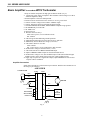
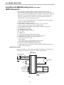
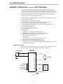
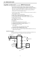
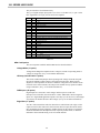
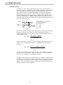
The components on the J17 header socket determine the overall response of the
amplifier. The standard setup is for flat gain. Some components must be changed for
tachometer operation. If the gain is too high in tachometer mode, alternate component
values are suggested which will reduce the gain by a factor of 3, and 5. The table below
lists the components on J17 for the various setups:
C4
R5
C6
R7
Flat
330 pF
46.4 K
10 nF
0
Tach
330 pF
499 K
10 nF
10 M
Tach/3
1 nF
150 K
33 nF
3M
Tach/5
1.5 nF
100 K
47 nF
2M
Table 18
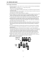
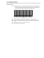
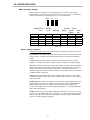
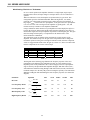
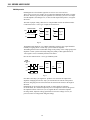
The diagram on the following page illustrates the frequency response of the servo
preamplifier in the different gain configurations. Here are some equations for the
important points on the performance curve. These all apply to the servo preamplifier
stage as driven by the input differential amplifier through a 50K ohm resistor (R11) ,
with tachometer feedback coming through a 50K ohm resistor (R1+R2), and with the
Feedback trimpot set to the fully CW position. Turning this pot fully CCW will add an
additional 21dB gain while maintaining the same frequency response. (See functional
diagram)
Parameter
Equation
DC Gain
ADC =
Low-frequency Break
Low-frequency Zero
Mid-frequency Gain
High-frequency Break
R5 + R 7
R11
1
f 1=
2 × π × R7 × C6
1
f2=
2 × π × R5 × C 6
R5
A MID =
R11
1
f 3=
2 × π × R5 × C 4
24
Flat
Tach
Tach/3
Tach/5
Unit
0.93
210
63
42
n/a
n/a
1.59
1.61
1.69
Hz
n/a
32
32
34
Hz
0.93
10
3
2
n/a
10.4
0.97
1.06
1.06
KHz