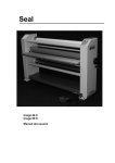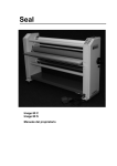
1
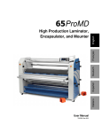
Seal Image 60 C Image 60 S Owners Manual Contents Subject Page Contents Illustrations Limited Warranty on Seal Image Laminators Introduction Using this manual 2 3 4 5 5 Features and benefits of the Image 60C/S Safety information Safety features General information General use 7 9 10 13 13 Technical specification Identification Un-crating and moving the Image 60C/S Operating conditions Connecting to the electric supply 14 14 15 16 16 Main switch Control panel 60C Control panel 60S Control panel Emergency stop buttons 17 19 21 22 25 Emergency stop trip wire Roller up/down and roller pressure Supply shafts Unwind brake Loading rolls 25 26 28 28 29 Feed-in table Image guide Front take-up shaft Feeding images Laminating and Adhesive coating (Decaling) 30 30 31 31 32 Mounting Pre-coating Cleaning and maintenance Troubleshooting Glossary of laminating terms 34 35 36 39 40 Accessories Conversion lists 41 42 2 Illustrations Subject Page Features and benefits of the Image 60C/S Working space Identification Wood blocks Main switch 6 12 14 15 17 Control panel Image 60C Control panel Image 60C when rotation of roller is active Control panel Image 60S Emergency stop button Emergency stop trip wire 18 19 20 25 25 Roller up/down and roller pressure Unwind brake Supply shaft Feed-in table Mounting / Dismounting image guide 26 28 29 30 30 Front take-up shaft Decaling (with liner) Decaling (without liner) Mounting decals Chain tensioning 31 32 32 34 37 Lubrication 38 3 Limited Warranty on Seal Image Laminators Seal Graphics warrant to the original consumer purchaser that all new Seal Image Laminators that prove defective in materials or workmanship within the applicable warranty period will be repaired or, at our option, replaced without charge. The applicable warranty shall be one year from date of purchase. This warranty does not apply if it is found that at any time the equipment has not been used for its intended purpose. “Original consumer purchaser” means the person whom first purchased the product covered by this warranty other than for purpose of resale. The warranty extends to and is enforceable only by the original consumer purchaser, and only for the period (during the applicable term) which the product remains in the procession of the original consumer purchaser. The warranty does not cover accidental damage or misuse. For more information regarding this warranty, please contact your local distributor. WARNING: Changes or modifications to this unit not expressly approved by the party responsible for compliance could void the users authority to operate this equipment. NOTE: This equipment has been tested and found to comply with the limits for machinery directive 89/392, Low Voltage Directive 73/23, EMC Directive 89/336. This limits are designed to provide reasonable protection against harmful interference when the equipment is operated in a commercial environment. WARNING: Any unauthorised changes or modifications to this unit will void the users warranty and will transfer health and safety obligations to the user. Seal Graphics Europe BV Kanaaldijk O.Z. 3 P.O. Box 29 NL - 8100 AA Raalte Tel: Fax: Internet: + 31 572 345 500 + 31 572 345 501 www.sealgraphics.com 4 Introduction Thank you for purchasing the IMAGE 60C/S laminator. It has been designed to give you years of reliable service. The IMAGE 60C/S brings a new level of simplicity and ease of use to image finishing. By following the guidelines outlined in this manual for proper care and maintenance, you can depend on receiving any years of trouble-free profitability from your investment. Reading your Owners Manual will familiarise you with the particular features, operational features and guidelines of your laminator. The Manual includes instructions on various laminating techniques an diagrams that give you the comprehensive information needed for needed for safe, efficient use of your laminator. The basic knowledge provides the foundation of creative, innovative uses you can build on, as you achieve the basic skills trough practice. The IMAGE 60C/S meets applicable EC Directives. Using This Manual Special Markings WARNING: Please pay special attention to all passages marked this way. This information is vital to the proper use and maintenance of the laminator and the safety of users. Passages marked this way give information on the efficient use of the laminator 5 Features and Benefits of the Image 60C/S 11 8 1 9 6 5 2 4 3 7 10 6 Features and Benefits of the Image 60C/S Image 60C: 1. Digital touch pad control-panel with LED indicators and preset settings for, 60C: speed, nipopening, pressure and additionally for the 60S, temperature. 2. Hand wheel for up and down movement of top roller. 3. Knob pre-pressure control for setting pre-pressure of top roller. 4. Swinging feed-in table for easy loading, with integrated Emergency Stop System. 5. Image guide to help feed-in images and to prevent paper handling problems, and is removable when mounting. 6. High-release silicone rollers prevent adhesive build-up and make cleaning easy. 7. Pivoting, cantilevered supply shafts with integrated unwind brake for easy loading and webbing. Both shafts are of the auto-grip design and are mounted on the rear of the machine. 8. Front take-up shaft for winding up the release liner off some laminates and adhesives. 9. Emergency stop button at both sides of the laminator. 10. Identification plate detailing manufacturing information and CE mark. 11. Sturdy, stand-alone design with fitted castors allow the machine easily moved and feet levelled . Image 60S: 1. Fast, electric heating and independent temperature control with infra-red control for maximum accuracy. Optional equipment: Optionally, equipment comprising an unwinding and a winding unit is available. This allows you to work “roll to roll”. If you require more information on this matter, please contact your local supplier. This optional equipment is described in the manual ‘Image 60 roll to roll’. 7 8 Safety Information The IMAGE 60C/S laminator is provided with safety equipment to promote safe machine operation. You should however take note of the following. Read and make sure you understand these safety and operating instructions. WARNINGS: Hot surfaces – Danger of getting injured by hot parts. Be careful with hot parts. The heated rollers can have a surface 0 0 temperature of up to 135 C (275 F). Do not touch the rollers. Even after the laminator has been switched off, the rollers remain hot for a long time. Rotating parts – Danger of getting injured by rotating parts. The laminator is equipped with an opto-electronic protective device to avoid contact with the rotating rollers. Make sure that these safety provisions are always in operation/fitted. Make sure that clothing, long hair etc. are not caught by the rotating rollers which might result in being trapped. The motor will stop automatically when the opto-electronic protective device in front of the main rollers is interrupted. THIS DOES NOT HAPPEN when the combined operation of the slowmode and the foot pedal is being used. In this case the laminator will only work at 0.5 m/min (1.6ft/min) and while the slow-mode is being used an audible signal will be heard. Electric parts – Danger of getting injured by electricity. Do not remove the side panels of the IMAGE 60C/S laminator because there is a danger of getting injured by electricity. Only remove panels to carry out maintenance. In this case make sure the main electrical supply is off. Do not put heavy objects on the power supply cable. Danger of damage to equipment or injury to persons. This indicates the possibility of damage to equipment or injury to persons if the wrong tools or equipment are used. 9 Safety Features Emergency stop buttons There are two Emergency Stop buttons and they are located on top of the right and left cabinets of the laminator. They stop the rotation of the rollers and should only be used in case of an emergency. Emergency stop trip wire One emergency stop trip wire is located at the front side close to the bottom side of the laminator. The switch is installed at the right cabinet. Any touching of the wire stop the rotation of the rollers and should only be used in case of an emergency. Opto-electronic protective device These self-checking photo-eyes prevent foreign objects from passing in between the rollers. The opto-electronic protective device is set for use in the factory and should not be adjusted except by a service representative. Main electrical switch The main electrical supply “ON/OFF” switch is positioned on the backside of the right cabinet. Slow (snail) mode by foot pedal WARNING: With this feature the opto-electronic protective device at the nip point of the rollers will be temporarily disengaged, the rotation of the rollers will not stop automatically when human body parts, clothing, long hair etc. will reach in the nip point. Press the button to activate the slow mode function, an audible signal will be heard and LED [6] comes on. Press the foot pedal, the machine will rotate slowly forward at a fixed speed of 0.5 m/min (1.6ft/min). The LED [8] will come on. Release the foot pedal to stop rotation of the rollers. Press the button again to deactivate the slow mode function. Locking Cabinets The cabinets which house the inner workings of the laminator can be opened only with a screwdriver. Reset proceed before start of the machine 1. Set the main electrical switch to the “I” (ON) position 2. Rotate the two emergency buttons and pull the blue reset button of the emergency stop trip wire. 3. Set the speed at 5 and press the start button to rotate the machine until the slow mode LED comes on flashing for few seconds, the slow mode control is enabled for use now, press the stop button to stop the rotation. 4. Machine is ready for use now. 10 Safety Features The forward rotation of the rollers will stop when: The opto-electronic protective device in front of the main rollers is interrupted. NOTE: This does not happen when the combined slow mode and foot pedal function is used. An emergency stop button is pressed. The emergency stop trip wire is touched by foot or by hand. The feed-in table is turned out of its operating position. The stop button on the control panel is pressed. The foot pedal is pressed for a short moment. The reverse button is pressed for a short moment. If a motor overload occurs. WARNING: Use of the inside of cabinets for storage may cause possible injury and/or damage to the inner workings and will void the warranty. 11 General Information Minimum room length = 8 feet / 2.5 meter maximum board length 62 inch / 1575 mm 24 inch / 600 mm room length = 2x max. boarrd length + 27 inch / 68 cm roll of laminate maximum board length room width = 15 feet / 4.5 meter Working Space 12 General Information Power Sources – Only connect the laminator to the power supply specified on the identification label. Refer to the “Specifications” chapter in this manual for more information. Water and Moisture – Install an RCD (GFI in U.S.A.) in the buildings electrical supply if the laminator is used near water or in an area of high humidity. Environment – Use your laminator in the cleanest, most dust free environment possible to produce the highest quality output. The Image 60C consumes approximately 0.25 kW and the Image 60S consumes approximately 4 kW of electricity. Because of the heat generated by the Image 60S, the laminator should not be in the same room as an electrostatic plotter, etc. Working Space – The laminator requires a working area large enough to allow the safe and efficient use. An area 4,5m x 6,0m (15ftx20ft) would be the smallest recommended. See previous page. Rollers – NEVER cut or slice directly on any of the roller surfaces as any resultant damage is not covered by the warranty. ALWAYS use cutters with enclosed blades to prevent cutting rollers and to avoid expensive replacement costs. Do not feed objects such as staples, paper clips and rough or abrasive materials through the laminating rollers. Keep all objects such as tools, rulers, pens, markers, etc. away from the roller opening. Refrain from leaving such items on the feed-in table to prevent them accidentally being fed into the rollers. Servicing and Replacement Parts – Refer all servicing to your distributor. Servicing by any unauthorised technician voids the warranty. WARNING: When the laminator is not in use , always ensure that the top roller has been raised to prevent flat spots from developing. Flat spots will effect the quality of the output and is not covered by the warranty. General Use The IMAGE 60C/S greatest quality is its simplicity. With it, a low-skilled operator is able to mount and laminate quickly, even continuously. SAFETY IS IMPORTANT DO NOT OPERATE YOUR LAMINATOR IN AREAS OF EXTREME HUMIDITY. KEEP HAIR, JEWELLERY AND LOOSE CLOTHING AWAY FROM THE LAMINATOR DURING OPERATION. ALWAYS TURN THE LAMINATOR OFF AND DISCONNECT FROM THE ELECTRICAL SUPPLY BEFORE OPENING THE SIDE CABINETS WHICH HOUSE THE INNER WORKINGS OF THE LAMINATOR. 13 Technical Specification Maximum working width: Maximum roller width: Maximum roller nip opening: Maximum substrate thickness: Maximum roller speed: Maximum roller temperature (only top roller 60S) Core inner diameter Dimensions Net weight Shipping weight Power supply Power supply Maximum power consumption Maximum power consumption Dimensions roll to roll option 60C: 60S: 60C: 60S: 62 66 1 3/16 1 15 275 3 Width: 85 Depth: 27 Height: 56 950 1060 1N/PE 200 – 250 VAC 3N/PE 200 – 250 VAC inches inches inches inches feet/min 0 F inches inches inches inches lbs lbs 50 – 60 Hz 50 – 60 Hz 1575 1675 30 25 4.6 135 75 2160 680 1410 430 480 1 14 -16 250 4000 mm mm mm mm m/min 0 C mm mm mm mm kg kg A A W W Depth: inches 890 mm 35 60S Although 3 phase supply is used, it is not a true 3 phase machine, phase 1, neutral and ground (earth) are connected. The information contained herein is general and does not constitute any warranties or guaranties. Identification The machine has an identification plate. On the Image 60C/S it is located on the rear at the connection frame. 14 Un-crating and Moving The Image 60C/S Your Image 60C/S laminator is supplied in its own custom designed box with integral 4-way entry pallet and its wrapped in plastic film to prevent moisture penetration. WARNING: If lifting the pallet from the end the forklift must be fitted with extensions that support the whole length of the box. NOTE: If future transportation of the laminator is a possibility, the pallet, crate and securing bolts should be kept in safe place. To remove laminator from its box, please follow the instructions below: Step 1 – Cut the straps securing the carton to the pallet and remove the carton. Step 2 – Remove the plastic bag. Step 3 – Remove the four securing bolts, (located on the back and front of each cabinet at the bottom) that hold the laminator to the pallet using the provided 19mm open-ended spanner. Push down the internal thread end at the front of the right hand cabinet side (underneath green switch). Step 4 – Turn down the four laminator levelling feet (4x) to lift the laminator, use the provided 17mm open-ended spanner. Step 5 – Remove the wooden blocks (2x) sideways. Put the two ramps to the pallet. Step 6 – Unscrew the support block on one side, to make it turn 900. Step 7 – Turn away the block to make room for the laminator to pass by. Step 8 – Turn up by going round the four laminator levelling feet (4x) to make the laminator stand on the wheels. The laminator is now standing on its four swivel castors. Step 9 – Pull the laminator off the pallet and slowly roll the laminator down the ramps onto the floor. Carefully push the laminator to its final location. WARNING: Step 9 should only be carried out by two or more people. Do not attempt to do it your own. Step 10 – Cut the ties securing the two wooden blocks to the rollers, move up the top roller and remove the wooden blocks. Wooden block Wooden Blocks 15 Operating Conditions Temperature 0 0 0 0 10 C - 50 C (50 F - 122 F) Do not expose the laminator to direct sunlight as output quality may be affected. Moisture 30% ~ 95% non-condensing Ideal humidity ~ 55% Dust Avoid a dusty environment because the films used on this laminator will attract dust and the output quality will be affected. Connection to the Electrical Supply In process of setting up your IMAGE 60C/S, the laminator will require to the electrical supply. This should only be carried out by a qualified person. NOTE: The laminator is supplied with a 2.5 meter (8 feet) cable including a mains plug, in accordance with the identification plate. If the plug has to be changed, then the wire colours mean: In case of single phase operation 60C: Cable colours: Green/Yellow Brown Blue Ground (Earth) Live phase 1 Neutral In case of three phase operation 60S: Cable colours: Green/Yellow Brown Blue Ground (Earth) Live phase 1 Live phase 2 not used Live phase 3 not used Neutral Should you have any questions regarding the installation of your IMAGE 60C/S, please contact your local Distributor. 16 Main Switch The main electrical supply “ON/OFF” switch is located on the backside of the right cabinet. The rocker switch of the IMAGE 60C has two positions: “0” Supply voltage OFF “1” Supply voltage ON Main Switch 60C The rotary switch of the IMAGE 60S has two positions: “0” Supply voltage OFF “1” Supply voltage ON Main Switch 60S 17 Control Panel 1 11 2 3 12 13 6 14 4 5 15 7 8 16 9 10 Control panel Image 60 C 18 Control Panel Control panel 60 C No. Action or Indication 1. This LED indicates that the setting of the nip opening is showed in mm (SI Unit). 2. This LED indicates that the setting of the nip opening is showed in inches (Imperial). 3. The digital display shows the setting of the nip opening in mm or inches or when the start mode is activated, the current in Amps. 4. This LED indicates that the reverse function is activated. 5. Reverse button - keep this button pressed to operate the machine in reverse mode. 6. This LED indicates that the slow mode function is activated. 7. Slow mode button - press the button to activate the slow mode function, an audible signal will be heard and LED 6 comes on. Press the button again to deactivate. 8. This LED indicates that the forward mode function is activated. 9. Start button - press the button to operate the machine in forward mode 10. Stop button - press the button to stop the rotating parts of the machine. 11. This LED indicates that the value of the nip line pressure is showed in SI units (N/mm). 12. This LED indicates that the value of the nip line pressure. is showed in Imperial units (lbs/inch). 13. The digital display shows the pre-setting/value of the nip line pressure in N/mm (lbs/inch). 14. This LED indicates that the photoelectric safety device beams are not interrupted. 15. This LED indicates that the motor is overloaded. 12 and 15. When both LED’s are flashing, an emergency button has been activated. 16. Speed adjustment control knob. 3 8 Control panel Image 60 C (LED 8 ON) 19 Control Panel 20 25 21 26 22 27 28 23 29 24 30 1 11 2 3 12 13 6 14 4 5 15 7 8 16 9 10 Control panel Image 60 S 20 Control Panel Control panel 60 S No. Action or Indication 0 20. This LED indicates that the set-point of the roller temperature is showed in C (degrees Celsius). 0 21. This LED indicates that the set-point of the roller temperature is showed in F (degrees Fahrenheit). 22. The digital display shows the set-point of the roller temperature. 23. Heater “ON” button. This switches on the heater of the top roller. 24. Heater “OFF” button. This switches off the heater of the top roller. 25. This LED indicates that the temperature of the top roller is above set point. 26. Increase temperature set-point button. 27. This LED indicates that the temperature of the top roller is at set point 28. This LED indicates that the temperature of the top roller is below set point. 29. Decrease temperature set-point button. 30. This LED indicates that the heater is on. 21 Control Panel The laminators control panel is situated on the front right. The control panel of the 60C is divided into 2 sections, motor control section and display section. The control panel of the 60S is divided into 3 sections, motor control section, display section and heater control section. MOTOR CONTROL SECTION The rotation of the rollers is started as follows: 1. Set the machine for the necessary process as is prescribed by Seal Graphics. 2. Select the necessary mode to operate the machine. Normal forward mode To operate the machine continuously forward, press the start button [ 9 ]. The LED [8] will come on. Set speed higher than “1”, the rollers will start rotating. The machine is stopped by the following: 1. Press the Stop button – Normal stopping mode. 2. Interruption of the opto-electronic protective device by finger, hand or material, The LED [14] will be off. 3. Press either of the two emergency buttons. 4. Press the emergency stop trip wire by foot or hand. 5. If a motor overload occurs, LED [15] will come on on. 6. Briefly operate the foot pedal for a very short time. 7. Set the speed adjustment control knob at 0. The rollers stop rotating when the speed is set at ‘0’. However, the operating mode is still active. Reverse mode To operate the machine in reverse, keep the reverse button pressed. The LED [4] will come on. The rollers will rotate in reverse at a fixed speed of 0,5 m/min (20 inch/min). Release the button to stop the rotation of the rollers. Using reverse mode can damage the process. Before using this mode, be sure that is necessary. WARNING: In this mode, the in-running nip at the backside is not protected by a safety device the rotation of the rollers will not stop automatically when human body parts, clothing, long hair, etc. reach in the inrunning nip. 22 Control Panel Foot pedal The foot pedal is connected by cable to the machine and has to be positioned at the floor in front of the laminator. The foot pedal can be used to rotate the rollers in forward mode or in slow (snail) mode. Keep the foot pedal pressed to operate the rollers. Release the foot pedal to stop rotation of the rollers. Slow (snail) mode WARNING: In this mode, the in-running nip at the front-side is not protected by a safety device the rotation of the rollers will not stop automatically when human body parts, clothing, long hair, etc. reach in the in-running nip. Press the button to activate the slow mode function, an audible signal will be heard and the LED [6] comes on. Press the foot pedal, the machine will rotate slowly forward at a fixed speed of 0,5 m/min (20 inch/min). The LED [8] will come on. Releasing the foot pedal to stop rotation of the rollers. Press the button again to deactivate the slow mode function, LED [6] will then go off. . Changing from slow-mode to normal running mode without stopping (to prevent stop marks on the substrate): during slow mode, keep the foot pedal pressed and press the forward mode button, but do not release the foot pedal yet. next, release the foot pedal. finally release the forward button. Changing from normal running mode to slow-mode without stopping: during forward mode, press the slow mode button, an audible signal will be heard and the LED 6 comes on. press the foot pedal. releasing the foot pedal will stop rotation of the rollers. 23 Control Panel DISPLAY SECTION Left display shows roller nip setting or motor current. When roller rotation mode is not active: the roller nip setting is shown in the left display, rotate hand wheel to move roller up or down. When roller rotation mode is active: the motor current is shown in Amps. Right display shows roller pre-pressure setting or actual roller pressure. When the top roller does not touch the bottom roller or material: the display shows pre-pressure setting. When the top roller is touching the bottom roller or material: the display shows current line pressure, only when value is higher than set pre-pressure value. HEATER CONTROL SECTION This section controls the temperature of the top roller. Before switching the heater “ON”, move the top roller up until it is free not touching the bottom roller (to prevent hot spots on the top and bottom roller. Press heater button “ON” to start warming up of the top roller. Press increase or decrease set point button to set process operating temperature. During heating up the “heater ON LED” [30] is on and the “below set point LED” [28] is on. At the end of the heating up period, the “heater on LED” [30], the “above set point LED” and the “at set point LED” [27] will flash until the top roller will become steady at the set point temperature. When the temperature of the top roller is at set point the “heater ON LED” [30] will go off and the “at set point LED” [27] will be on. 0 0 From cold, the laminator takes approximately 30 minutes to reach 120 C (250 F). The heater will 0 0 maintain the selected temperature to within ±5 C (9 F).across the entire roller face. It is quite normal that, during and after the process, the “set point LED’s” [25,27,28] and the “heater on LED” [30] occasionally flash. This indicates that the temperature controller is maintaining the roller temperature within the set point bandwidth. 24 Emergency Stop Buttons Emergency stop buttons There are two buttons and they are located on top of the right and left cabinets of the laminator. They stop the rotation of the rollers and should only be used in case of an emergency. Once pressed these buttons lock, and must be rotated to be reset before the laminator can be used again. See also safety information section. Emergency Stop Trip Wire Emergency stop trip wire One emergency stop trip wire is located at the front side close to the bottom side of the machine. The switch is installed at the front of the right cabinet. Touching the wire by foot or hand stops the rotation of the rollers and should only be used in case of an emergency. Once activated this switch locks. The emergency stop trip wire must be reset by pulling the blue button on top of the switch, before the laminator can be used again. See also safety information section. 25 Roller up/down and roller pressure Roller UP/DOWN handle Pre-pressure setting knob Roller up/down Rotation of the hand wheel clockwise will move the roller down, the value of the nip setting (the thickness of the panel to be laminated) is shown in the display [3]. Rotation of the hand wheel counter-clockwise will move the roller up. The nip setting can be set for values: –1.0 mm to 27.0 mm (-3/16” to 1 1/16”) Roller pre-pressure setting Rotation of the pre-pressure knob clockwise will increase the roller pre-pressure, the value of the pre-pressure is shown in the display [13]. Rotation of the pre-pressure knob counter-clockwise will decrease the roller pre-pressure, the value of the pre-pressure is shown in the display[13]. The pre-pressure can be set for values 0.63 N/mm to 1.60 N/mm ( 3.60 Lbs/inch to 9.10 Lbs/inch ). Recommended starting pre-pressure is 1.10 N/mm ( 6.30. Lbs/inch ) WARNING: Take care that the maximum value of pressure does not exceed 1.70 N/mm. Excessively high pressure will damage machine parts. WARNING: Display value above 1.60 N/mm will result in the following being displayed: 1.70 N/mm - 1.90 N/mm > flashing, 2.00 N/mm > EEE and laminator will stop. 26 Roller up/down and roller pressure Setting pre-pressure and nip opening when processing panels Example: Mounting print at recommended pre-pressure of 1.00 N/mm. Panel thickness 10 mm. 1. Set pre-pressure to 1.00 N/mm, it is recommended to turn knob clockwise to set the prepressure. 2. Rotate the hand wheel clockwise to move the top roller down for the needed nip setting, until the nip setting display [13] shows a value of 10.0mm. It is recommended to move the top roller down to set the nip opening. 3. It is recommended to carry out a nip pressure test as follows: a. Place panel in front of rollers. b. Start the rotation of rollers in forward mode and push the panel into the nip. c. The display of the nip opening will change and show the motor current in Amps (i.e. A0.5) d. Stop the rotation of the rollers when the panel is about 50mm ( 2 inches ) into the nip. e. The display of the nip opening and pre-pressure will change to a higher value, do not worry and do not adjust anything. The increase shows that the pre-pressure has been reached. f. The display shows the current nip pressure. If the value does not change, the thickness of the panel may be to less. Move the roller down by rotation of the hand wheel until the pre-pressure value increases 1-3 digits. g. If necessary, the nip pressure can be reduced now. Use the hand wheel for moving up and down the roller to adjust. The nip pressure value during process must always be at least 1-3 digits higher than the set pre-pressure. h. Start reverse rotation of the rollers until the panel is out of the nip. i. The displays will show pre-set values, 1-3 digits difference does not give problems and does not need a pre-set again. 4. The top roller now is pre-set for the mounting job. 5. Prepare mounting as recommended by Seal. 6. Bring panel with prepared print in front of rollers. 7. Start the rotation of rollers in forward mode and push the panel into the nip. 8. When the mounting is finished, stop rotation of rollers. Setting nip opening and pre-pressure when processing laminates 1. Set pre-pressure to 0.70 N/mm, it is recommended to turn the knob clockwise to set the prepressure. 2. Rotate the hand wheel clockwise to move the roller down until the pressure display value increases over 0.70 N/mm. 3. The recommended pressure for laminates is 1.10 N/mm to 1.20 N/mm. 4. Do not worry about value of the roller height display when processing laminates, the pressure is the important parameter. 27 Supply shafts Unwind brake Knob for unwind brake tension Unwind brake tension setting Rotation of the knob clockwise will increase the unwind brake tension. Rotation of the knob counter-clockwise will decrease the unwind brake tension. During the process, the film tension is shown by the motor current in Amps. Rotation of rollers without web tension will show a value of approximately A0.5. By increasing the brake tension the current value will increase to A1.0 – A2.0. To achieve best results, adjust tension for top and bottom films step by step, i.e. top a little then the bottom. WARNING: The maximum continuous current is 2.3. If the current stays too long above 2.3, the motor overload circuit will come active and the rotation of the rollers will stop. This can damage the job which is in process. NOTE: When the diameter of the film rolls decreases, the web tension must be decreased also to avoid overload. 28 Supply shafts Loading rolls The machine has 2 pivoting, cantilevered supply shafts with integrated unwind brake for easy loading and webbing. One supply shaft is located at the top rear side of the laminator and one supply shaft is located at the bottom rear side of the laminator. Both shafts are of the auto-grip design. To load film, rotate the supply shaft in a position that the rubber blocking cords are on the top and bottom of the shaft. Release the unwind tension if necessary, to turn the shaft to the correct position. Pull the top and/or bottom unwind shaft out of the snap-in bracket and turn backside upon pivot. Load the required roll(s) onto the supply shaft(s). Turn the supply shaft back and push into the snap-in bracket. Centre the rolls on the supply shaft by using the integrated tape measure. WARNING: Do not overload the supply shafts while loading/unloading. 29 Feed-in table The machine has: • A Swinging feed-in table for easy loading, with integrated Emergency Stop System. • An Image guide to help feed-in images and to prevent paper handling problems, and is removable when mounting. Before swinging the table remove the Image guide” and store underneath the laminator at a safe place. The swinging feed-in table has 2 lock bolts. To be able to swing the table open for easy webbing, first pull the left hand lock bolt and rotate to lock it. Then pull the right hand lock bolt and swing feed-in table open.` WARNING: Hold the table by hand when unlocking to prevent accidents. When the table is in the open position, easy webbing the film from the bottom supply shaft is possible. NOTE: If the table is swung open, it is not possible to start the rotation of the rollers. After webbing, swing the table back to the operating position and make sure that both lock bolts snap into position. the right hand lock bolt snaps in and rotate and snap in the left hand lock bolt. WARNING: Do not sit or stand on the table. 30 Front take-up shaft • Front take-up shaft for winding-up the release liner of some laminates and adhesives. The take-up shafts have integrated wind-up clutches and spring activated cones for easy loading and webbing. One take-up shaft is located at the top front side of the laminator and one take-up shaft is located at the bottom front side of the laminator. To remove the plastic tube, push it to the left side against the spring activated cone and take out the plastic pipe. Take an empty film core and hit at one end to create a flat spot, slide the core on to the plastic tube. Place the plastic tube at the spring activated cone at the left hand side, push and place the free end of the plastic tube at the right hand side cone. The take-up shaft is now ready for webbing. Feeding Images To aid feeding images, the laminator is equipped with an “Image guide”. The “Image guide” can be positioned in front of the top roller at the feed-in table. The “Image guide” prevents the images from lifting away from the table during feeding, or from interrupting the opto-electronic protective device. How to feed images: Step 1 – For good results, the process requires that the images must be fed through correctly. The leading edge of each image must be flat all the way across. Any wrinkles or creases in the image will show when encapsulated perhaps even magnified. To aid feeding, the leading edge should also be straight. Step 2 – Feed the image into the machine ensuring that the edge is parallel to the roller. NOTE: Do not stop the motor whilst an image is being finished as this can cause marks in the output. 31 Laminating and Adhesive Coating (Decaling) This process involves sandwiching an image between either a hot or cold laminate on the face of the image and a pressure-sensitive adhesive on the rear. This process can be used to create self adhesive images for mounting down on various substrates. 1. 2. 3. 4. 5. 6. 7. 8. Top roller (60S heated top roller) Bottom roller Top supply shaft Top idler Top take-up shaft Bottom supply shaft Bottom idler Bottom take-up shaft Decaling with liner 1. 2. 3. 4. 5. 6. 7. 8. Top roller (60S heated top roller) Bottom roller Top supply shaft Top idler Top take-up shaft Bottom supply shaft Bottom idler Bottom take-up shaft Decaling without liner 32 Laminating and Adhesive Coating (Decaling) Preparation Select the films that you will use on the top and bottom of the images, it is advisable to use slightly wider width films compared to the print width. This way the print can be trimmed with a border. Mount rolls onto the supply shafts with adhesive facing you. Web as follows: Step 1a – Films with liner, pull the film down from the top unwind and thread under the idler bar. Connect the film and liner to the take-up shaft with a piece of tape. The take-up shaft should have a scrap core placed over it to allow easy removal of the scrap liner. Split the film from the release liner and pull the film evenly across the face of the rollers. Step 1b – Films without liner, pull the film down from the top unwind and thread under the idler bar, unless pressure-sensitive is used, then thread above idler. Pull the film evenly over the top roller and across the face of the rollers. Step 2 – Remove the “Image guide” and swing the feed-in table open. NOTE: Check if the film widths of the upper and lower web are the same! Step 3 – Pull the pressure-sensitive adhesive up from the bottom supply shaft across the face of the bottom roller and place evenly across the top roller. The films will then stick together. Step 4 – Bring the feed-in table in operating position. Step 5 – Lower the top roller, start slow mode and press foot pedal and use a piece of card as leader to push the films into the nip of the rollers. Press the foot pedal until the end of the leader reaches the middle of the feed-out table. Release the foot pedal. Step 6 – Start the rotation of the laminator to run the film and adjust the roller pressure by turning the hand wheel and adjust the top and bottom supply shaft tension by turning the brake knob until any wrinkles or creases in the films over the face of the rollers are reduced to a minimum. They should clear within approximately 1m ( 3 – 4 feet ). If the wrinkles persist, cut the films and web the laminator again. Step 7 – Place the “Image guard on the feed-in table. YOU ARE NOW READY TO FEED IMAGES. 33 Mounting This process involves mounting down previously made decals onto a substrate. No films or adhesives are used in this process. To mount decals onto a substrate Step 1 – Place the mounting board on a flat surface. Lay your image face down on the mounting board and expose approximately 25 mm ( 1” ) of the adhesive by peeling back the release liner along one of the edges. Fold the release paper back making an even crease. Step 2 – Turn the image over and carefully position the exposed adhesive edge of the image squarely onto the board. Step 3 – Once positioned correctly, press the image firmly down onto the exposed adhesive from the centre toward the edges to ensure smooth surface. This is the edge that will be fed into the rollers first. Step 4 – Ensure that the pre-pressure and nip setting of the rollers corresponds to the board type and thickness. Step 5 – Push the edge of the board into the rollers, start slow mode and press the foot pedal until the board and image are just caught by the nip. Step 6 – Flip the in tacked portion of the image over the top roller with one hand so that the release paper can be peeled off the image with the other hand. Press foot pedal to feed the board through the rollers. At this point, forward rotating of the rollers can be started by pressing the start button, set speed by speed control knob. NOTE: Take care that the release liner is not grabbed by the rollers. Step 7 – When the end of the board is near to the nip, you should slow the machine down. To do this, just press the foot pedal to start slow mode. Releasing the foot pedal will stop the machine. 34 Mounting Step 8 – Remove the image from the rear of the laminator and trim if necessary. If the board is accidentally sent in too far at first, the release liner will get caught and will be impossible to pull back. In this case, stop and reverse the rotation of roller until the liner can be pulled away. The image must be held against the roller while the board feeds through to prevent wrinkles. As the process becomes more familiar, the speed of the laminator may be increased to make the process more efficient. Take care that the opto-electronic protective device is not tripped by the release liner. Pre-Coating This process is used to coat substrates with a pressure-sensitive adhesive onto which images can be mounted. The same process is used to create a carrier board (sled). Preparation: Mount the roll of self wound pressure-sensitive adhesive on the top supply shaft of the laminator with the exposed adhesive facing you. Have a leader board ready with the same thickness as the boards to be coated. Step 1 – Pull the adhesive down from the unwind station and over the top roller evenly, and down across the face of both main rollers. Swing the feed-in table open for a moment to do this. Step 2 – Measure the thickness of the board(s) to be coated and set the pre-pressure setting and nip setting at the correct value. Step 3 – Start slow mode and press the foot pedal and using the leader board, push the pressuresensitive adhesive film into the roller nip. Release the foot pedal when the rear edge of the leader board is almost leaving the roller nip. Step 4 – Position the board to be coated into the nip, and choose one of the three speed settings. When coating boards, ensure that the next board to be coated follows the previous board without any gaps. Step 5 – Follow the last board being coated with the leader board once again to allow the final board to clear the laminating rollers and then stop the motor and raise the top roller. 35 Cleaning & Maintenance Cleaning Remove the electrical power before commencing any maintenance on the laminator. Do not use an abrasive cleaner on any surface. It may damage the surface of the silicone rollers or the paint work. Only use a damp cloth. Do not let water get onto panels of the laminator as they are not sealed. If water enters the electrical circuits, injury to persons or damage to the equipment when power is applied may occur. 1. External Surfaces Clean the external surfaces of the laminator with a damp cloth. If necessary, use household detergent to remove difficult stains. 2. Cleaning the silicone rollers Clean the rollers with a clean damp cloth. If necessary, use household detergent to remove any residual film. Use an “Image Roller Cleaner” to remove excess adhesive. This should be done with the top roller hot. When cleaning the top roller, place a scrap piece of board under the top roller to reduce waste adhesive falling onto the bottom roller. NOTE: The rollers should be cleaned every day or the adhesive will build up and may eventually damage the rollers. Check the rollers regularly for dents, flat sides, cuts etc. to ensure optimum quality of your work. Use personal protective equipment when cleaning: i.e. safety glasses and appropriate gloves. 3. Feed-in table Wipe the table with a dry cloth as necessary 4. Feed-out table Wipe the table with a dry cloth as necessary 36 Cleaning & Maintenance Maintenance Remove of right cover 1. Remove the hand wheel for roller up/down. Press the central plastic cap at one end to swivel it, than remove it for access to the screw and washer. 2. Remove the screw using a 5 mm Allen key and the remove the hand wheel. 3. Turn the pre-pressure knob until the hexagon cap nut is free. Remove the hexagon cap nut using a 13 mm ring spanner and remove knob. 4. Remove the 4 tap screws with Philips no. 2 screwdriver. 5. Remove cover. Remove of left cover 1. Remove the 4 screws with Philips no. 2 screwdriver 2. Remove cover. Chain tensioning 1. Check chain tension twice a year. 2. To tension chain if too slack. use a 5mm Allen key to loosen the 2 bolts securing the top motor and move motor down to tension the chain. Re-tighten the 2 bolts. 3. Then loosen the 2 bolts securing the bottom motor and move motor up to tension the chain. Tighten the 2 bolts. 37 Cleaning & Maintenance Lubrication 1. The roller up/down screw threads at right and left side should be lubricated twice a year. Use a acid-free Vaseline to lubricate at both sides of the plastic nut. 2. Lubricate the chains with chain grease, if appropriate. 3. For the 60S heated top roller, lubricate the brass block at the right journal. Use Molykote D-321R to spray once a year. NOTE: For technical assistance, please contact your distributor. 38 Troubleshooting Problem: The laminator has no display Solution 1: Ensure that the mains supply to the laminator is O.K. Solution 2: Unplug the laminator. Check the fuses on the main control board situated in the right cabinet. This should only be done by authorised safety or maintenance personnel. Spare fuses are located on the upper horizontal cable channel. Problem: The rotation of the rollers will not function. Solution 1: Ensure that the emergency stop buttons have not been activated, rotate them to reset. Solution 2: Ensure that the emergency stop trip wire have not been activated, pull to reset. Check wire tension, indicator on switch should be about the middle of the green ring. Solution 3: Make sure that opto-electronic protective device is not blocked. Solution 4: Make sure that the table is in the working position. Solution 5: Unplug the laminator. Check the fuses on the main control board situated in the right cabinet. This should only be done by authorised safety or maintenance personnel. 39 Glossary of Laminating Terms Encapsulating – Sandwiching an image between two heat activated films. Film – A synonym for laminate. The clear material used in the laminating and encapsulating processes. Feed-in – The side of the laminator from which the images are fed. Mounting – Affixing permanently an image onto some kind of backing board. Nip – The spot where the top and bottom rollers meet. Feed-out – The side of the laminator from which the completed images emerge. Release liner – The backing of a pressure-sensitive, heat-activated laminate or mounting adhesive. Once the release liner is peeled off, the adhesive layer becomes exposed. Decal – An image that have been laminated on top and has an adhesive backing. Leader board – A piece of stiff card or foam board used to lead film, etc. into the nip of the laminating rollers. Also used when pre-coating to prevent adhesive getting onto the rollers. Carrier board (Sled) – A board that has a non-stick surface that is used when laminating one side of an image only. These are sometimes made using a flat board coated with a self-wound pressuresensitive adhesive. The silicone release liner is not removed during coating and provides the necessary non-stick surface. Pre-coating – The process of coating a substrate with an adhesive mounting film onto which an image can be mounted. 40 Accessories The following accessories are supplied with the laminator: User manual Open ended spanner 19 mm (2x) Open ended spanner 17 mm (1x) Spare fuses The following accessories are recommended: Safety knife Rubber cleaning block Tape measure Ring spanner 13 mm Allen key 5 mm Philips no.2 screwdriver Empty film core Leader board 41 Conversion list Conversion list mm >> decimal inch inch >> mm mm inch dec inch mm 1 1.00 0.98 0.79 0.75 0.63 0.59 0.50 0.47 0.39 0.38 0.25 0.24 0.20 0.19 0.13 0.12 0.08 0.06 0.04 25.400 25 20 3/4 5/8 15 1/2 12 10 3/8 1/4 6 5 3/16 1/8 3 2 1/16 1 19.050 15.875 12.700 9.525 6.350 4.763 3.175 1.588 42 Conversion list Conversion list Roller line Roller line Roller line Roller line Force force force force N/mm kg/cm Lbs/inch Lbs/cm 0.60 0.60 3.42 1.35 0.63 0.63 3.60 1.42 0.70 0.70 4.00 1.57 0.80 0.80 4.57 1.80 0.90 0.90 5.14 2.02 1.00 1.00 5.71 2.25 1.10 1.10 6.28 2.47 1.20 1.20 6.85 2.70 1.30 1.30 7.42 2.92 1.40 1.40 7.99 3.15 1.50 1.50 8.56 3.37 1.60 1.60 9.13 3.60 1.70 1.70 9.70 3.82 43 Conversion list Conversion list Fahrenheit > Celsius Celsius > Fahrenheit Absolute F C C F 1 2 3 4 5 6 7 8 9 10 11 12 13 14 15 16 17 18 19 20 21 22 23 24 50 60 70 80 90 100 110 120 130 140 150 160 170 180 190 200 210 220 230 240 250 260 270 280 10 16 21 27 32 38 43 49 54 60 66 71 77 82 88 93 99 104 110 116 121 127 132 138 20 25 30 35 40 45 50 55 60 65 70 75 80 85 90 95 100 105 110 115 120 125 130 135 68 77 86 95 104 113 122 131 140 149 158 167 176 185 194 203 212 221 230 239 248 257 266 275 F C C F 1 2 3 4 5 6 7 8 9 10 0.6 1.1 1.7 2.2 2.8 3.3 3.9 4.4 5.0 5.6 1 2 3 4 5 6 7 8 9 10 1.8 3.6 5.4 7.2 9.0 10.8 12.6 14.4 16.2 18.0 Relative 1 2 3 4 5 6 7 8 9 10 44 46