1
Owner's
anuaR
®
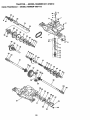
TRANSAXLE
L
TRACTO
Model No.
917.270510
• Safety
o Assembly
,, Operation
® Maintenance
,, Repair Parts
CAUTION:
Read and follow all
Safety Rules and Instructions
before operatingthis equip-
For answers to your questions
about this product, Call:
1-800-659-5917
Sears Craftsman i-I=elpLine
5 am - 5 pro, Mon - Sat
ment.
Sears, Roebuck and Co., Hoffman Estates, IL 60179
Maintenance .........................................
17
Service and Adjustments .................. _...21
Storage .................................................
27
Troubleshooting ....................................
28
Repair Parts .........................................
32
Parts Ordering ....................... Back Cover
Warranty .................................................
2
Safety Rules ...........................................
2
Product Specifications ........................... 5
Assembly ................................................
8
Operation ..............................................
11
Maintenance Schedule ......................... 17
LIMITED TWO YEAR WARRANTY
ON CRAFTSMAN
RIDING EQUIPMENT
For two (2) years from the date of purchase, if this Craftsman Riding Equipment is maintained, lubricated and tuned up according to the instructions in the owner's manual,
Sears will repair or replace, free of charge, any parts found to be defective in material or
workmanship.
This Warranty does not cover:
o Expendable items which become worn during normal use, such as blades, spark
plugs, air cleaners, belts, etc.
o Tire replacement or repair caused by punctures from outside objects, such as nails,
thorns, stumps, or glass.
o Repairs necessary because of operator abuse, negligence, improper storage or accident or the failure to maintain the equipment according to the instructions contained in
the owner's manual.
o Riding equipment used for commercial or rental purposes.
LIMITED 90 DAY WARRANTY
ON BATTERY
For ninety (90) days from date of purchase, if any battery included with this riding equipment proves defective in material or workmanship and our testing determines the battery will not hold a charge, Sears wilt replace the battery at no charge. In-home warranty
service on your Craftsman riding equipment is available at no charge for 30 days from
the date of purchase. Please contact your nearest service center. After 30 days from the
date of purchase, warranty service is available by taking your Craftsman riding equipment to your nearest Sears Service Center. (In-home warranty service will still be available after 30 days from the date of purchase but a standard trip charge will apply). This
warranty applies only while this product is in the United States. This Warranty gives you
specific legal rights, and you may also have other rights which may vary from state to
state.
Sears, Roebuck and Co., D/817 WA, Hoffman Estates, IL 60179
GENERAL OPERATION
° Read, understand,and follow all instructions in the manual and on the machine
before starting.
• Only allow responsibleadults, who are
familiar withthe instructions,to operate
the machine.
° Clear the area of objects such as rocks,
toys, wire, etc_,which could be picked
up and thrown by the blade.
• Be sure the area is clear of other people
before mowing. Stop machine if anyone
enters the area.
° Never carry passengers.
= Do not mow in reverse unless absolutely necessary.Always look down and
behind before and while backing.
= Be aware of the mower dischargedirection and do not point it at anyone. Do
not operate the mower withouteither
the entiregrass catcher or the guard in
place.
° Slow down before turning.
o Never leave a runningmachine unattended. Alwaystum off blades, set parking brake, stop engine, and remove
keys before dismounting.
2
o Do not try to stabilize the machine by
puttingyour foot on the ground.
a Do not use grass catcher on steep
slopes.
CHILDREN
Tragic accidents can occur if the operator
is not alert to the presence of children.
Children are often attracted to the
machine and the mowing activity.Never
assume that children will remain where
you last saw them.
o Keep children out of the mowing area
and under the watchful care of another
responsibleadult.
o Be alert and turn machine off if children
enter the area.
o Before and when backing, look behind
and down for small children.
° Never carry children. They may fall off
and be seriously injured or interferewith
safe machine operation.
° Never allow childrento operate the
machine.
o Use extra care when approachingblind
comers, shrubs, trees, or other objects
that may obscure vision.
SERVICE
o Turn off blades when not mowing.
o Stop engine before removing grass
catcher or unclogging chute.
o Mow only in daylight or good artificial
light.
o Do not operate the machine while under
the influence of alcohol or drugs.
, Watch for traffic when operating near or
crossing roadways.
= Use extra care when loading or unloading the machine into a trailer or truck.
SLOPE OPERATION
Slopes are a major factor related to lossof-control and tipover accidents, which
can result in severe injury or death. All
slopes require extra caution. If you cannot
back up the slope or if you feel uneasy on
it, do not mow it.
DO:
• Mow up and down slopes, not across.
o Remove obstacles such as rocks, tree
limbs, etc.
° Watch for holes, ruts, or bumps. Uneven
terrain could overturn the machine. Tall
grass can hide obstacles.
o Use slow speed. Choose a low gear so
that you will not have to stop or shift
while on the slope.
o Follow the manufacturer's recommendations for wheel weights or counterweights to improve stability.
o Use extra care with grass catchers or
other attachments. These can change
the stability of the machine.
o Keep all movement on the slopes slow
and gradual. Do not make sudden
changes in speed or direction.
° Avoid starting or stopping on a slope, if
tires lose traction, disengage the blades
and proceed slowly straight down the
slope.
DO NOT:
• Do nottum on slopes unless necessary,
and then, tum slowly and gradually
downhill, if possible.
° Do not mow near drop-offs, ditches, or
embankments. The mower could suddenly turn over if a wheel is over the
edge of a cliff or ditch, or if an edge
caves in.
o Do not mow on wet grass. Reduced
traction could cause sliding°
• Use extra care in handling gasoline and
other fuels. They are flammable and
vapors are explosive.
Use only an approved container.
Never remove gas cap or add fuel
with the engine running.Allow engine to cool before refueling. Do n,ot
smoke.
- Never refuelthe machine indoors.
Never store the machine or fuel
container inside where there is an
open flame, such as a water heater.
,, Never run a machine inside a closed
°
°
o
°
3
area.
Keep nuts and bolts, especially blade
attachment bolts, tight and keep equipment in good condition.
Never tamper with safety devices.
Check their proper operation regularly.
Keep machine free of grass, leaves, or
other debris build-up. Clean oil or fuel
spillage. Allow machine to cool before
stodng.
Stop and inspect the equipment if you
strike an object. Repair, if necessary,
before restarting.
Never make adjustments or repairs with
the engine running.
Grass catcher components are subject
to wear, damage, and deterioration,
which could expose moving parts or
allow objects to be thrown. Frequently
check components and replace with
manufacturer's recommended parts,
when necessary.
Mower blades are sharp and can cut.
Wrap the blade(s) or wear gloves, and
use extra caution when servicing them.
Check brake operation frequently.
Adjust and service as required.
o Be sure the area is clear of other people
before mowing. Stop machine if anyone
enters the area.
,, Never carry passengers.
o Do not mow in reverse unless absolutely necessary. Always look down and
behind before and while backing.
• Never carry children. They may fall off
and be seriously injured or interfere with
safe machine operation.
o Keep children out of the mowing area
and under the watchful care of another
responsible adult.
= Be alert and turn machine off if children
enter the area.
o Before and wheri backing, look behind
and down for small children.
= Mow up and down slopes (15 o Max), not
across.
° Remove obstacles such as rocks,tree
limbs, etc.
o Watch for holes, ruts, or bumps. Uneven
terrain could overturnthe machine° Taft
grass can hide obstacles.
° Use slow speed. Choose a low gear so
that you will not have to stop or shift
while on the slope.
° Avoidstarting or stoppingon a slope. If
tires lose traction,disengage the blades
and proceed slowly straightdown the
slope.
° Do not turn on slopes unless necessary,
and then, turn slowly and gradually
downhill,if possible.
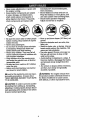
_Look
for this symbol to point out important safety precautions. It means CAUTION!H BECOME AWARE!!! YOUR SAFETY IS INVOLVED.
,_kWARNING- The engine exhaust from
this product contains chemicals known to
the State of California to cause cancer,
birth defects, or other reproductive harm.
,_CAUTION: In order to prevent accidental starting when setting up, transporting,
adjusting or making repairs always disconnect spark plug wire and place wire where
it cannot contactspark plug.
4
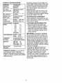
PRODUCT
SPECRFICATIONS
GASOLtNE
CAPACITY
AND TYPE:
1.25 GALLONS
UNLEADED
REGULAR
OIL TYPE
(API-SF/SG/SH):
SAE 30 (above 32°F)
SAE 5W-30
(below 32°F)
01L CAPACITY:
&0 PINTS
SPARK PLUG:
(GAP: .030")
Champion RC12YC
STD361458
VALVE
CLEARANCE:
INTAKE:
.005"-.007"
EXHAUST: .009"-o011"
GROUND SPEED
MPH):
FORWARD:
I sT
2 ND
3RD
4 TM
5 TM
6 TM
Should you experience any problem you
cannot easily remedy, please contact your
nearest Sears Authorized Service Center.
We have competent, well-trained technicians and the proper tools to service or
repair this tractor.
Please read and retain this manual The
instructions will enable you to assemble
and maintain your tractor properly. Always
observe the "SAFETY RULES".
MAINTENANCE
A Sears Maintenance Agreement is available on this product°Contact your nearest
Sears store for details.
CUSTOMER
1.0
1.3
2.1
3ol
4.0
5.1
1.6
TIRE PRESSURE:
FRONT: 14 PSI
REAR: 10 PSI
CHARGING
SYSTEM:
3 AMPS BATTER'{
5 AMPS HEADLIGHTS
RESPONSIBILiTiES
o Read and observe the safety rules.
o Follow a regular schedule in maintaining, caring for and using your tractor.
• Follow the instructions under "Maintenance" and "Storage" sections of this
owner's manual.
_kWARNING:
This tractor is equipped
with an internal combustion engine and
should not be used on or near any unimproved forest-covered, brush-covered or
grass-covered land unless the engine's
exhaust system is equipped with a spark
arrester meeting applicable local or state
laws (if any). tf a spark arrester is used, it
should be maintained in effective working
order by the operator.
In the state of California the above is
required by law (Section 4442 of the
California Public Resources Code). Other
states may have similar laws. Federal
laws apply on federal lands. A spark
arrester for the muffler is available through
your nearest Sears Authorized Service
Center (See REPAIR PARTS section of
this manual).
AMP/HR:
25
MIN. CCA:
190
CASE SIZE: U1R
BLADE BOLT
TORQUE:
AGREEMENT
27-35 FT. LBS.
CONGRATULATIONS
on your purchase
of a Craftsman Tractor. it has been
designed, engineered and manufactured
to give you the best possible dependability
and performance.
5
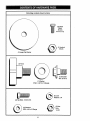
Parts Bag contents shown full size
\
(2) Sheet
Metal
Screws
#10-16 × 1/2
(1) Locknut
318_24
(1) Large Flat Washer
(1) Knob
(1) Shoulder
Bolt 5/16-18
(1) Washer
17132 x 1-3/16 x 12 Gauge
Washers
(2) Lock 1/4
(2) Hex Bolts 1/4-20 x 3/4
(2) Washers
9/32 x 5/8 x 16 Gauge
Nuts
(2) Hex
1/4-20
6
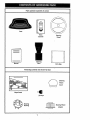
Parts packed separately in carton
Seat
Video
Cassette
Steering
Boot
Manual
_
...............
:L
:
:
Steering
Wheel
::::
..........
;:
............................
/
.
_
ii
j[l_l_l_
ii
L.
Parts Bag
,,,_rrrr,
...........
:
::::::
:
::
:
:
...........
_
._.,:,
I
IJ
_
:ll_ll)J
Parts Bag contents not shown full size
Steering
Wheel
Insert
Slope Sheet
(2) Keys
__
Bushing
teering
Steering Wheel
Adapter
:
fl
r _IIII[:,
:;
:
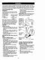
Your new tractor has been assembled at the factory with exception of those parts left
unassembled for shipping purposes. To ensure safe and proper operation of your tractor
all parts and hardware you assemble must be tightened securely. Use the correct tools
as necessary to insure proper tightness. Review the video cassette before you begin.
TOOLS REQUIRED
ASSEMBLY
FOR
o Snap steering wheel insert into center
of steering wheel.
o Remove protective materials from tractor hood and grill.
IMPORTANT: Check for and remove any
staples in skid that may puncture tires
where tractor is to roll off skid.
A socket wrench set will make assembly
easier° Standard wrench sizes you need
are
(1)
(2)
(1)
(1)
listed below.
9/16" wrench
1/2" wrench
Pliers
Utility knife
(2) 7/16" wrenches
(1) Phillips Screwdriver
(1) Tire pressure
gauge
When right or left hand is mentioned in
this manual, it means, from your point of
view, when you are in the operating position (seated behind the steering wheel).
Insert
_
_
TO REMOVE TRACTOR FROM
CARTON
Steering _L
UNPACK CARTON
o Remove all accessible loose parts and
parts boxes from shipping carton (See
page 6).
o Cut, from top to bottom, along lines on
all four corners of shipping carton, and
lay panels flat.
o Check for any additional loose parts or
boxes and remove.
BEFORE
ROLLING
TRACTOR
SKiD
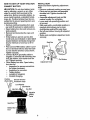
ATTACH STEERING WHEEL
318-24 Locknut
Large Fiat Washer
_
Steerin_ WI__
i g wnee
Adapter _
Steering
(Assembly
Position)
M,.ertal^,
Steering
Bushing
Tabs
..
OFF
Steering Shaft
(Shipping
Position)
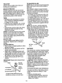
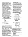
o Slide the steering bushing over the
steering shaft.
, Raise steering shaft forward until screw
holes in dash line up with steering bushing. Install two (2) sheet metal screws
and tighten securely.
° Position steering boot over steering
shaft.
o Place tabs of steering boot over tab
slots in dash and push down to secure.
° Slide steering wheel adapter onto upper
steering shaft.
° Position front wheels of the tractor so
they are pointing straight forward.
° Position steering wheel so cross bars
are horizontal (left to right) and slide
onto adapter.
o Assemble large flat washer and 3/8-24
locknut and tighten securely.
TO ROLL TRACTOR OFF SKID (See
Operation section for location and
function of controls)
° Press lift lever plunger and raise attachment lift lever to its highest position.
° Release parking brake by depressing
clutch/brake pedal,
° Place gearshift lever in neutral (N) position.
° Roll tractor forwards off skid.
• Remove banding holding discharge
guard up against tractor.
8
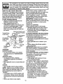
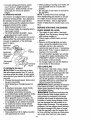
HOW TO SET UP YOUR TRACTOR
CONNECT
BATTERY
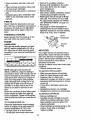
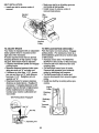
,_CAUTION: Do not short battery terminals by allowing a wrench or any other
object to contact both terminalsat the
same time. Before connectingbattery, remove metal bracelets, wristwatchbands,
rings,etc. Positiveterminal must be connected first to prevent sparking from accidental grounding.
o Remove cardboard packingfrom seat
pan and lift seat pan to raised position.
o Open battery box door and remove protective plastic.
o Remove terminal protective caps and
discard.
o If this battery is put into service after
month and year indicatedon label (label
located between terminals) charge battery for minimum of one hour at 6-10
amps.
o First connect RED battery cable to positive (+) terminal with hex bolt, flat washer, lock washer and hex nutas shown.
Tighten securely.
° Connect BLACK groundingcable to
negative (-) terminal with remaininghex
bolt, flat washer, lockwasher and hex
nut. Tighten securely.
o Close battery box door. Open battery
box door for:
o Inspectionfor secure connections
(to tighten hardware).
° inspectionfor corrosion.
° Testing battery.
° Jumping (if required).
° Periodic charging,
iNSTALL SEAT
Adjustseat before tighteningadjustment
knob.
o Remove cardboard packingon seat pan.
,, Place seat on seat pan and assemble
shoulder bolt. Tighten shoulderbolt
securely.
, Assemble adjustment knob and flat
washer loosely.Do not tighten.
o Lower seat intooperating positionand
sit on seat.
o Slide seat untila comfortableposition is
reached which allows you to press
clutch/brake pedal all the way down.
• Get off seat withoutmoving its adjusted
position.
o Raise seat and tighten adjustment knob
securely.
Seat
Seat Pan
Shoulder
Flat Washer
Adjustment
Positive
DiscardTerminal
(Red) Cable ProctectiveCaps
Lock Washer
Rat Washer
Hex
\
Hex Bolt
Negative
(Black)
Seat Pan
Battery
Door
9
Knob
CHECK DECK LEVELNESS
For best cutting results, mowerhousing
should be properly leveled.See "TO
,/CHECKLIST
PLEASE REVIEW THE FOLLOWING
CHECKLIST:
LEVEL MOWER HOUSING" in the
Service and Adjustments section of this
manual.
,/
,/
,I
CHECK FOR PROPER POSITION OF
ALL BELTS
See the figures that are shown for replacing motion and mower blade drive belts in
the Service and Adjustments sectoin of
this manual. Verify that the belts are routed correctly.
CHECK BRAKE SYSTEM
After you learn howto operate your tractor, checkto see that the brake is properly
adjusted. See "TO ADJUST BRAKE" in
the Service and Adjustmentssection of
this manual.
,/"
,/
J
,/"
4
All assembly instructions have been
completed.
No remaining loose parts in carton.
Battery is properly prepared and
charged. (Minimum 1 hour at 6 amps).
Seat is adjusted comfortably and
tightened securely.
All tires are properly inflated. (For
shipping purposes, the tires were
overinflated at the factory).
Be sure mower deck is properly leveled
side-to-side/front-to-rear
for best
cutting results. (Tires must be properly
inflated for leveling).
Check mower and drive belts. Be sure
they are routed properly around pulleys
and inside all belt keepers.
Check wiring. See that all connections
are still secure and wires are properly
clamped.
WHILE LEARNING HOW TO USE YOUR
TRACTOR, PAY EXTRA ATTENTION TO
THE FOLLOWING IMPORTANT ITEMS:
,," Engine oil is at proper level.
,/' Fuel tank is filled with fresh, clean,
regular unleaded gasoline.
¢" Become familiar with all controls - their
location and function. Operate them
before you start the engine.
,/ Be sure brake system is in safe
operating condition.
10
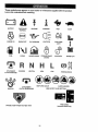
These symbols may appear on your tractor or in literature supplied with the product.
Learn and understand their meaning.
BATTERY
FAST
CAUTION OR
WARNING
REVERSE
FORWARD
ENGINE OFF
OIL PRESSURE
LIGHTS ON
CHOKE
MOWER HEIGHT
PARKING BRAKE
LOCKED
OVER TEMP
LIGHT
ENGINE ON
FUEL
ATTACHMENT
CLUTCH ENGAGED
REVERSE
NEUTRAL
HIGH
KEEP AREA CLEAR
IGNITION
ATTACHMENT
CLUTCH DISENGAGED
SLOW
UNLOCKED
MOWER LIFT
L
c®) I
LOW
PARKING BRAKE
SLOPE HAZARDS
(SEE SAFETY RULES SECTION)
FREE WHEEL
(AutomaticModels onty)
DANGER, KEEP HANDS AND FEET AWAY
11
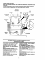
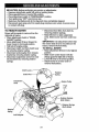
KNOW YOUR TRACTOR
READ THIS OWNER'S MANUAL AND SAFETY RULES BEFORE OPERATING YOUR
TRACTOR
Compare the illustrations with your tractor to familiarize yourself with the locations of
various controls and adjustments. Save this manual for future reference.
Attachment
Clutch Lever
Ammeter
ThrottleChoke
Ignition
\\
Light
Switch
Switch
LiftLever
Plunger
Control \\.\.
Clutch/Brake
Pedal
Attachment
Lever
Lift
O
Gearshift
Lever
Parking Brake
Our tractors conform to the safety standards
National Standards
Institute.
ATTACHMENT CLUTCH LEVER: Used
to engage the mower blades, or other
attachments mounted to your tractor.
of the American
GEARSHIFT LEVER: Selects the speed
and direction of tractor.
ATTACHMENT LIFT LEVER: Used to
raise, lower, and adjust the mower deck or
other attachments mounted to your tractor.
LIFT LEVER PLUNGER: Used to release
LIGHT SWITCH: Turns the headlightson
and off.
THROTTLE/CHOKE CONTROL: Used
for starting and controllingengine speed.
CLUTCH/BRAKE PEDAL: Used for
declutchingand braking the tractor and
startingthe engine.
PARKING BRAKE: Locks clutct-,Jbrake
pedal intothe brake position.
attachment lift lever when changing its
position.
IGNITION SWITCH: Used for starting and
stopping the engine.
AMMETER:
Indicates battery charging (+)
or discharging (-).
12
The operation of any tractor can result in foreign objects thrown into the
eyes, which can result in severe eye damage. Always wear safety glasses or eye shields while operating your tractor or performing any adjustments or repairs. We recommend a wide visiOn safety mask over the
spectacles, or standard safety glasses.
HOW TO USE YOUR TRACTOR
"/our tractor is equipped with an operator
presence sensing switch. When engine
is running, any attempt by the operator to
leave the seat without first setting the
parking brake will shut off the engine.
TO SET PARKING BRAKE
o Depress clutch_rake pedal into full
"BRAKE" position and hold.
• Place parking brake lever in
"ENGAGED" position and release pressure from clutch/brake pedal. Pedal
should remain in "BRAKE" position.
Make sure parking brake will hold tractor secure.
AttachmentClutch Lever
Throttle/Choke
Control lever
Pedal "Drive"
Position \
Position
STOPPING
MOWER BLADES ° To stop mower blades, move attachment clutch lever to "DISENGAGED"
position.
GROUND DRIVEo To stop ground drive, depress
clutch/brake pedal into full "BRAKE"
position.
° Move gearshift lever to neutral (N) position.
ENGINE ° Move throttle control to slow position.
NOTE" Failure to move throttle control to
slow position and allowing engine to idle
before stopping may cause engine to
"backfire".
° Turn ignition key to "OFF" position and
remove key. Always remove key when
leaving tractor to prevent unauthorized
use.
NOTE: Under certain conditions when
tractor is standing idle with the engine running, hot engine exhaust gases may
cause "browning" of grass. To eliminate
this possibility, always stop engine when
pping tractor on grass areas.
CAUTION. Always stop tractor completely, as described above, before leaving
the operator's position; to empty grass
catcher, etc.
THROTTLE CONTROL
Always operate engine at full throttle.
° Operating engine at less than full throttle reduces the battery charging rate.
o Full throttle offers the best bagging and
mower performance.
TO MOVE FORWARD AND BACKWARD
The direction and speed of movement is
controlled by the gearshift lever.
o Start tractor with clutch/brake pedal
depressed and gearshift lever in neutral
(N) position.
o Move gearshift lever to desired position.
° Slowly release clutch/brake pedal to
start movement.
iMPORTANT: Bring tractor to a complete
stop before shifting or changing gears.
Failure to do so will shorten the useful life
of your transaxle
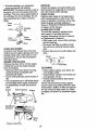
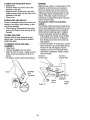
TO ADJUST MOWER CUTTING HEIGHT
The position of the attachment lift lever
determines the cutting height.
o Grasp lift lever.
° Press plunger with thumb and move
lever to desired position.
The cutting height range is approximately 1-1/2 to 4'L The heights are measured
from the ground to the blade tip with the
engine not running. These heights are
approximate and may vary depending
upon soil conditions, height of grass and
types of grass being mowed.
° The average lawn should be cut to
approximately 2-1/2 inches during the
cool season and to over 3 inches during
hot months. For healthier and better
looking lawns, mow often and after
moderate growth.
o Never use choke to stop engine.
13
o For best cutting performance, grass
over 6 inches in height should be
mowed twice. Make the first cut relatively high; the second to desired
height.
TO OPERATE MOWER
o When pushing or towing your tractor, be
sure gearshift lever is in neutral (N)
position.
• Do not push or tow tractor at more than
five (5) MPH.
NOTE: To protect hood from damage
"(our tractor is equipped with an operator
presence sensing switch. Any attempt by
the operator to leave the seat with the
engine running and the attachment clutch
engaged will shut off the engine.
o Select desired height of cut.
o Start mower blades by engaging attachment clutch control.
o TO STOP MOWER BLADES - disen-
whentransportingyourtractoron a truck
or a trailer, be sure hood is closed and
secured to tractor. Use an appropriate
means of tying hood to tractor (rope, cord,
etc.).
BEFORE
,_age attachment clutch control.
CAUTION:
Do not operate the mower
without either the entire grass catcher, on
mowers so equipped, or the discharge
guard in place.
Attachment
Lift Lever
High
Attachment
Clutch Lever
"Engaged"
Position
"Disengag_
Position
Low
Position
_e
STARTING
THE ENGgNE
CHECK ENGINE OIL LEVEL
o The engine in your tractor has been
shipped, from the factory, already filled
with summer weight oil.
° Check engine oil with tractor on level
ground.
o Remove oil fill cap!dipstick and wipe
clean, reinsert the dipstick and screw
cap tight, wait for a few seconds,
remove and read oil level. If necessary,
add oil until "FULL" mark on dipstick is
reached. Do not overfill.
° For cold weather operation you should
change oil for easier starting (See "OIL
VISCOSITY CHART" in the Maintenance section of this manual).
= To change engine oil, see the Maintenance section in this manual.
ADD GASOLINE
_
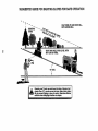
OPERATE ON HILLS
CAUTION: Do not drive up or down
hills with slopes greater than 15 ° and do
not drive across any slope. A slope guide
at the back of your manual is provided for
your use°
o Choose the slowest speed before starting up or down hills.
o Avoid stopping or changing speed on
hills.
° If slowing is necessary, move throttle
control lever to slower position.
o if stopping is absolutely necessary,
push clutch/brake pedal quickly to brake
position and engage parking brake.
• Move gearshift lever to 1st gear. Be
sure you have allowed room for tractor
to roll slightly as you restart movement.
• To restart movement, slowly release
parking brake and clutch/brake pedal.
° Make all turns slowly.
TO TRANSPORT
, Raise attachment lift to highest position
with attachment lift control.
° Fill fuel tank. Use fresh, clean, regular
unleaded gasoline with a minimum of
87 octane. (Use of leaded gasoline will
increase carbon and lead oxide
deposits and reduce valve life). Do not
mix oil with gasoline. Purchase fuel in
quantities that can be used within 30
days to assure fuel freshness.
IMPORTANT; When operating in temperatures below 32°F(0°C), use fresh, clean
winter grade gasoline to help insure good
dWweatherstarting.
ARNING: Experience indicates that
alcohol blended fuels (called gasohol or
using ethanol or methanol) can attract
moisture which leads to separation and
formation of acids during storage. Acidic
gas can damage the fuel system of an
engine while in storage. To avoid engine
problems, the fuel system should be emptied before storage of 30 days or longer.
Drain the gas tank, start the engine and
let it run until the fuel lines and carburetor
are empty. Use fresh fuel next season.
14
Instructions for additional
information. Never use engine or carburetor cleaner products in the fuel tank or pernent damage may occur.
CAUTION: Fill to bottom of gas tank
filler neck. Do not overfill. Wipe off any
spilled oil or fuel. Do not store, spill or use
gasoline near an open flame.
TO START ENGINE
When starting the engine for the first time
or if the engine has run out of fuel, it will
take extra cranking time to move fuel from
the tank to the engine.
o Sit on seat in operating position,
depress clutch/brake pedal and set
parking brake.
, Place gear shift lever in neutral (N) position.
o Move attachment clutch to "DISENGAGED" position.
o Move throttle control to choke position.
NOTE: Before starting, read the warm
and cold starting procedures below.
o Insert key into ignition and turn key
clockwise to "START" position and
release key as soon as engine starts.
Do not run starter continuously for more
than fifteen seconds per minute. If the
engine does not start after several
attempts, move throttle control to fast
position, wait a few minutes and try
again. If engine still does not start,
move the throttle control back to the
See Storage
choke position and retry.
WARM WEATHER STARTING (50 ° F and
above)
When engine starts, move the throttle
control to the fast position.
o The attachments and ground drive can
now be used. If the engine does not
accept the load, restart the engine and
allow it to warm up for one minute using
the choke as described above.
COLD WEATHER STARTING ( 50 ° F AND
BELOW)
o When engine starts, allow engine to run
with the throttle control in the choke
position until the engine runs roughly,
then move throttle control to fast position. This may require an engine warmup period from several seconds to several minutes, depending on the temperature.
o The attachments can also be used during the engine warm-up period.
NOTE: If at a high altitude (above 3000
feet) or in cold temperatures (below 32 F)
the carburetor fuel mixture may need to be
adjusted for best engine performance.
See "TO ADJUST CARBURETOR"
in the
Service and Adjustments section of this
manual.
NOTE= At a high altitude (above 3000
feet) or in cold temperatures (below 32 F)
the carburetor fuel mixture may need to be
adjusted for best engine performance.
See "TO ADJUST CARBURETOR" in the
Service and Adjustments section of this
manual.
15
o When mowing large areas, start by turning to the right so that clippings will discharge away from shrubs, fences, driveways, etc. After one or two rounds,
mow in the opposite direction making
left hand turns until finished
o If grass is extremely tall, it should be
mowed twice to reduce load and possible fire hazard from dried clippings.
Make first cut relatively high; the second
to the desired height.
o Do not mow grass when it is wet. Wet
grass will plug mower and leave undesirable clumps, Allow grass to dr,/
before mowing.
° Always operate engine at full thro_tle
when mowing to assure better mowing
performance and proper discharge of
material. Regulate ground speed by selecting a low enough gear to give the
mower the best cutting performance as
well as the quality of cut desired.
o When operating attachments, select a
ground speed that will suit the terrain
and give best performance of the at=
tachment being used.
MOWRNG TnPS
o Tire chains cannot be used when the
mower housing is attached to tractor.
o Mower should be properly leveled for
best mowing performance. See "TO
LEVEL MOWER HOUSING" in the
Service and Adjustments section of this
manual.
o The left hand side of mower should be
used for trimming.
o Drive so that clippings are discharged
onto the area that has been cut° Have
the cut area to the right of the machine°
This will result in a more even distribution of clippings and more uniform cuttingo
16
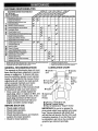
CUSTOMER RESPONSIBILITIES
AsYouCOMPL E
T
FI
.......
Check Brake Operation
_P' .........
_
Check'Tire Pressure
Check Operator Presence and
Interlock Systems
_
che'ck for Loose Fasteners
.... _
. _'
.....
.
,
..................
......
i _'7
J,
0
Check
Battery Level
_
R
.............
I_'
Check Transaxle Cooling
,AdjustBladeBelt(s)Tension
_'
V _'
......
_'s
Adjust Motion Drive Belt{s) Tension
_'s
,,,,,1,,
c.,eck.Eng_.e
O,L_vel
_
E
N
V_'_!
Ctean Air Screen
Replace Sp_
V_'2
P!ug ..............................
_
Rap!ace Air Filter Paper Cartridge
_'
......._=
............
Replace Fuel Filter
_/'
1 _ Change
more oft=n when operating urtder a heavy load ot In high ambient
2 - Service more often when operlatlng in dirty or dusty _nd_tten=
3 - If equipped
with eli fl[t_r, chm'tgo o!l avery SO hour_,.
GENERAL
BEFORE
°
o
°
,,
tornperaturo_
CHART
O S
Zerk
Spindle
Zerk
t'_r'
Front
Wheel
Front Wheel
"'_
Bearing Zerk
Bearing
Engine
@ Attachment
Clutch
Pivot(s)
:
SAE 30 or 10w30 Motor OiL
General Purpose Grease
.
Refer to Maintenance Engine Section
EACH USE
Check engine oil level.
Check brake operation.
Check tire pressure.
Check operator presence and interlock
systems for proper operation.
o Check for loose fasteners.
S - if equljopod w)th adjustable
ey_tom.
6 - Not required If equipped with m_fntenanco_freo
batto_,
7 - 33ghtan front axle p|vot bolt to 35 fL*tb_ m_xknum_
LUBRiCATiON
RECOMiVIENDATIONS
The warranty on this tractor does notcover
items that have been subjectedto operator
abuse or negligence. To receive full value
from the warranty, operator must maintain
tractor as instructedin this manual. Some
adjustments will need to be made periodically to properlymaintainyour tractor.
All adjustments in the Service and
Adjustments section of this manual should
be checked at least once each season.
,, Once a year you should replace the
spark plug, clean or replace air filter, and
check blades and beltsfor wear. A new
spark plug and clean air filter assure
proper air-fuel mixture and help your
engine run better and last longer.
................
IMPORTANT: Do not oil or grease the
pivot points which have special nylon bearings. Viscous lubricants will attract dust
and dirt that will shorten the Lifeof the selflubricating bearings, if you feel they must
be lubricated,use only a dry. powdered
graphite type lubricantsparingly.
17
TO SHARPEN BLADE
NOTE: We do not recommend sharpening
blade, but if you do, be sure the blade is
balanced.
Care should be taken to keep the blade
balanced. An unbalanced blade will cause
excessive vibration and eventual damage
to mower and engine.
• The blade can be sharpened with a file
or on a grinding wheel. Do not attempt
to sharpen while it is on the mower.
, To check blade balance, you will need a
5/8" diameter steel bolt, pin, or a cone
balancer. (When using a cone balancer,
follow the instructions supplied with balancer).
NOTE: Do not use a nail for balancing
blade. The lobes of the center hole may
appear to be centered, but are not.
• Slide blade onto an unthreaded portion
of the steel bolt or pin and hold the bolt
or pin parallel with the ground. If blade
is balanced, it should remain in a horizontal position. If either end of the blade
moves downward, sharpen the heavy
end until the blade is balanced.
TRACTOR
Akvays observe safety rules when performing any maintenance.
BRAKE OPERATION
If tractor requires more than six (6) feet
stopping distance at highspeed in highest
gear, then brake must be adjusted.(See
'3"0 ADJUST BRAKE" in the Service and
Adjustments section of this manual).
TIRES
o Maintain proper air pressure in all tires
(See "PRODUCT SPECIFICATIONS"
on page 5 of this manual).
• Keep tires free of gasoline, oil, or insect
controlchemicals whichcan harm rubber.
° Avoid stumps, stones, deep ruts, sharp
objects and other hazards that may
cause tire damage.
NOTE= To seal tire puncturesand prevent
flat tires due to slow leaks, tire sealant
may be purchased from your local parts
dealer. Tire sealant also preventstire dry
rot and corrosion.
BLADE CARE
For best results mower blades must be
kept sharp. Replace bent or damaged
blades.
BLADE REMOVAL
• Raise mower to highest position to allow
access to blades.
o Remove hex bolt, lock washer and flat
washer securing blade.
• install new or resharpened blade with
trailing edge up towards deck as shown.
o Reassemble hex bolt, lock washer and
flat washer in exact order as shown.
o Tighten bolt securely (27-35 Ft. Lbs.
torque).
IMPORTANT:
treated.
Center Hole
Blade
5/8" Bolt
or Pin
BATTERY
Your tractor has a battery charging system
which is sufficient for normal use° However, periodic charging of the battery with an
automotive charger will extend its lifeo
o Keep battery and terminals clean.
o Keep battery bolts tight.
• Keep small vent holes open.
° Recharge at 6-10 amperes for 1 hour.
NOTE= The original equipment batter./on
your tractor is maintenance free. Do not
attempt to open or remove caps or covers.
Adding or checking level of electrolyte is
not necessary,
Blade bolt is Grade 8 heat
Assembly
Bladh_er__
Fiat Was
Mandrel
Trailing
Edge Up
TO CLEAN BATTERY AND TERMINALS
LockWasher __...___]
Hex Bolt (Grade
Corrosion and dirt on the batter,./and terminals can cause the battery to "leak"
power.
,, Remove terminal guard.
G,Disconnect BLACK battery cable first
then RED batter./cable and remove
battery from tractor.
*A Grade 8 heat treated bolt can be
identified by six lines on the bolt head.
18
+ Rinse the battery with plain water and
dry.
o Clean terminals and battery cable ends
with wire brush until bright.
o Coat terminals with grease or petroleum
jelly.
° Reinstall battery (See "CONNECT BATTERY" in the Assembly section of this
manual).
V=BELTS
Check V-belts for deteriorationand wear
after 100 hours of operationand replace if
necessary. The belts are not adjustable.
Replace belts if they begin to slipfrom
wear.
TRANSAXLE
, Catch oil in a suitable container.
o Remove oil fill cap/dipstick. Be careful
not to allow dirt to enter the engine
when changing oil.
+ Remove drain plug.
o After oil has drained completely, replace
oil drain plug and tighten securely.
o Refill engine with oil through oil fill dipstick tube. Pour slowly. Do not overfill.
For approximate capacity see "PRODUCT SPECIFICATIONS"
on page 5 of
this manual.
o Use gauge on oil fill cap/dipstick for
checking level. Be sure dipstick cap is
tightened securely for accurate reading.
Keep oil at "FULL" line on dipstick.
COOUNG
Oil Fill
Keep transaxlefree from build-upof dirt
and chaff which can restrictcooling.
/_Cap/Dipstick
ENGINE
LUBRICATION
Only use high qualitydetergent oil rated
withAPt service classificationSF, SG or
SH. Select the oil's SAE viscositygrade
accordingto your expected operatingtemperature.
SAE VISCOSITY GRADES
*F
.20"
D"
30*
_2" 40"
_"
gO"
11_
NOTE: Although multi-viscosity oils
(5W30, 10W30 etc.) improve starting in
cold weather, these multi-viscosityoilswill
result in increased oil consumptionwhen
used above 32°F. Check your engine oil
level more frequently to avoid possible
engine damage from runninglow on oil.
Change the oil after ever,./25 hours of
operation or at least once a year if the
tractor is not used for 25 hoursin one
year.
Check the crankcase oil level before starting the engine and after each eight (8)
hours of operation. Tighten oil fill capldipstick securely each time you check the oil
level.
TO CHANGE ENGINE OIL
Determine temperature range expected
before oil change. All oil must meet APt
serviceclassificationSF, SG or SH.
= Be sure tractor is on level surface.
• Oil will drain more freely when warm.
Oil Drain
Plug
AIR FILTER
"Yourengine will not run properly using a
dirty air filter. Clean the foam pre-cleaner
after every 25 hours of operation or every
season. Service paper cartridge every 100
hours of operation or every season,
whichever occurs first.
Service air cleaner more often under dusty
conditions.
° Remove knob(s) and cover.
TO SERVICE PRE-CLEANER
o Slide foam pre-cleaner offcartridge.
, Wash it in liquid detergent and water.
o Squeeze it dry in a clean cloth.
, Saturate it in engine oil. Wrap it in clean,
absorbent cloth and squeeze to remove
excess oil.
,, If very dirty or damaged, replace precleaner.
- Reinstall pre-cleaner over cartridge.
° Reinstall cover and secure with knob(s).
TO SERVICE CARTRIDGE
• Remove cartridge nut.
, Carefullyremove cartridgeto prevent
debrisfrom entering carburetor.Clean
base carefullyto prevent debris from
enteringcarburetor.
,, Clean cartridge by tapping gently on flat
surface. If very dirty or damaged,
replace cartridge.
19
o Reinstall cartridge,nut, precleaner,
cover and secure with knob(s).
BMPORTANT: Petroleum solvents, such as
kerosene, are not to be used to clean the
cartridge. They may cause deterioration of
the cartridge. Do not oil cartridge. Do not
use pressurized air to clean or dry cartridge.
Cover ..................
?
Knob
_
Foam
Cartridge
_
Paper
Pre-Cleaner_
Cartddge
_'_Base
CLEAN AiR SCREEN
Air screen must be kept free of dirt and
chaff to prevent engine damage from overheating. Clean with a wire brush or compressed air to remove dirt and stubborn
dried gum fibers.
ENGINE COOUNG FINS
Remove any dust, dirt or oil from engine
cooling fins to prevent engine damage
from overheating.
o Remove screws from blower housing
and lift housing and dipsticktube
assembly off engine.
° Cover oil fill openingto prevent entry of
dirt.
o Use compressed air or stiffbristlebrush
to thoroughlyclean engine coolingfins.
= To reassemble, reverse above procedure.
Screws
Blower Housing
MUFFLER
Inspect and replace corroded muffler and
spark arrester (if equipped) as it could create a fire hazard and!or damage.
SPARK PLUGS
Replace spark plugs at the beginning of
each mowing season or after every 100
hours of operation,whichever occursfirst.
Spark plug type and gap setting are
shown in "PRODUCT SPECIFICATIONS"
on page 5 of this manual.
IN-LINE FUEL FILTER
The fuel filter should be replaced once
each season. If fuel filter becomes
clogged, obstructingfuel flow to carburetor, replacement is required.
o With engine cool, remove filter and plug
fuel line sections.
o Place new fuel filter in positionin fuel
line with arrow pointingtowards carburetor.
Be sure there are no fuel line leaks and
clam.
CLEANING
o Clean engine, battery, seat, finish, etc.
of all foreign matter.
° Keep finished surfaces and wheels free
of all gasoline, oil, etc.
° Protect painted surfaces with automotive type wax.
We do not recommend usinga garden
hose to clean your tractor unless the electrical system, muffler,air filter and carburetor are covered to keep water out. Water
in engine can result in a shortened engine
life.
air screen
Dil
Assembly
PLug
Engine Cooling
2O
,_IkCAUTION:
o
,,
o
°
o
o
Before performing
any service or adjustments:
Depress clutch/brake pedal fully and set parking brake.
Place gearshiftlever in neutral (N) position.
Place attachment clutch in =DISENGAGED" position.
Turn ignitionkey =OFF" and remove key.
Make sure the blades and all movingparts have completelystopped.
Disconnectspark plugwire from spark plug and place wire where it cannot come
in contactwith plug.
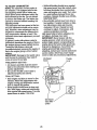
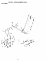
TO REMOVE MOWER
o Disconnect front links from deck by
removing retainer springs.
• Raise lift lever to raise suspension
arms. Slide mower out from under tractor.
IMPORTANT= If an attachment other than
the mower deck is to be mounted on the
tractor, remove the front links.
TO INSTALL MOWER
o Raise attachment lift lever to its highest
position.
o Slide mower under tractor with discharge guard to right side of tractor.
° Lower lift lever to its lowest position.
o Install mower in reverse order of
removal instructions.
Mower will be easier to remove from the
right side of tractor.
o Place attachment clutch in "DISENGAGED" position.
° Move attachment lift lever forward to
lower mower to its lowestposition.
• Roll belt off engine pulley.
° Disconnectclutch rod from clutch lever
by removing retainer spring.
° Disconnectanti-swaybar from chassis
bracket by removing retainer spring.
o Disconnectsuspensionarms from rear
deck brackets by removing retainer
springs.
Clutch
Retainer
Spring
Clutch
Suspension
Arms
Engine Pulley
Front
Link
_r Springs
(BothSides)
Springs
(Both Sides)
Retainer
Spring
Anti-Swaybar
21
TO LEVEL MOWER HOUSING
Adjustthe mower while tractor is parked
on level ground or driveway. Make sure
tires are properlyinflated (See =PRODUCT SPECIFICATIONS"). If tires are
over or underinflated,you will not properly
adjust your mower.
o
o
•
SIDE-TO-SIDE ADJUSTMENT
,, Raise mower to its highestposition.
o At the midpointof both sidesof mower,
measure height from bottomedge of
mower to ground. Distance =A" on both
sides of mower should be the same or
within 1/4" of each other.
o if adjustment is necessary, make adjustment on one side of mower only.
o To raise one side of mower, tighten lift
link adjustment nut on that side.
o To lower one side of mower, loosen lift
linkadjustment nut on that side.
NOTE: Each full turn of adjustment nut
will change mower height about 1/8".
Bottom
•
o
°
equal in length. Both links should be
approximately 10-3/8%
if links are not equal in length, adjust
one link to same length as other link.
To lower front of mower loosen nut "E"
on both front links an equal number of
turns.
When distance "D" is 1/8" to 1/2" lower
at front than rear, tighten nuts "F"
against trunnion on both front links.
To raise front of mower, loosen nut "F"
from trunnion on both front links.
Tighten nut =E" on both front links an
equal number of turns.
When distance "D" is 1/8" to I/2" lower
at front than rear, tighten nut "F" against
trunnion on both front links.
Recheck side-to-side adjustment.
Mandrel
Bottom
Both Front Links Should be Equal in Length
Nut "E"
Trunnion
o Recheck measurements after adjusting.
FRONT-TO-BACK
ADJUSTMENT
IMPORTANT: Deck must be level side-toside. !f the following front-to-back adjustment is necessary, be sure to adjust both
front links equally so mower will stay
level side-to-s=de.
Front Links
Trunnton
TO REPLACE MOWER BLADE DRIVE
BELT (See Illustration Next Page)
The mower blade drive belt may be
replacedwithouttools. Park the tractor on
level surface. Engage parking brake.
To obtainthe best cutting results,the
mower housing should be adjustedso that
the front is approximately I/8" to 1/2"
lower than the rear when the mower is in
its highestposition.
Check adjustmenton right side of tractor.
Measure distance "D" directlyin front and
behind the mandrel at bottom edge of
mower housing as shown.
o Before making any necessary adjustments, check that both front links are
BELT REMOVAL,, Remove mower from tractor (See "TO
REMOVE MOWER" in this section of
this manual).
° Work belt off both mandrel pulleys and
idler pulleys.
°
PuU belt away from mower.
22
BELT INSTALLATION -
o Make sure belt is in all pulley grooves
and inside all belt guides.
o Install mower in reverse order of
removal instructions.
o Install new belt in reverse order of
removal.
Mandrel
Idler
Pulley
Pulleys
Mandrel
Pulley
TO ADJUST BRAKE
Your tractor is equipped with an adjustable
brake system which is mounted on the
right side of the transaxle.
tf tractor requires more than six (6) feet
stoppingdistance at high speed in highest gear, then brake must be adjusted.
o Depress clutch/brake pedal and engage
parking brake.
o Measure distance between brake operating arm and nut "A" on brake rod.
° If distance is other than 1-1/2", loosen
jam nut and tum nut "A" until distance
becomes 1-1/2". Retighten jam nut
against nut "A".
° Road test tractor for proper stopping
distance as stated above. Readjust if
necessary, if stoppingdistance is still
greater than six (6) feet in highest gear,
further maintenance is necessary.
Contact your nearest authorized service center.
TO REPLACE MOTION DRIVE BELT
Park the tractor on level surface. Engage
parking brake. For assistance, there is a
belt installationguide decal on bottom side
of left footrest.
• Remove mower (See "TO REMOVE
MOWER" in this section of this manual.)
o Remove belt from stationary idler and
clutching idler.
o Pull belt slack toward rear of tractor.
Remove belt upwards from transaxle
pulley by deflectingbelt keepers.
o Pull belt toward front of tractor and
remove downwards from around engine
pulley.
° Install new belt by reversing above procedure.
Engine
Pulley
_._,,\
Clutchi.Q
With Parking Brake "Engaged"
Stationary
Ii
I'
Nlll
"II
If
Ii
II
, ,or !1 IJ if
Transaxle _11
Pulley
Nut "A"
Jam Nut
Arm
23
¢F 13!!
--,i
TO ADJUST STEERING WHEEL ALiGNMENT
If steering wheel crossbars are not horizontal (left to right)when wheels are positioned straightforward, remove steering
wheel and reassemble per instructionsin
the Assemblysection of this manual.
FRONT WHEEL TOE-IN/CAMBER
The front wheel toe-in and camber are not
adjustableon your tractor.If damage has
occurredto affect the front wheel toe-in or
camber, contactyour nearest authorized
servicecenter.
TO REMOVE WHEEL FOR REPAIRS
o Block up axle securely.
o Remove axle cover, retaining ring and
washers to allow wheel removal (rear
wheel contains a square key - Do not
lose).
,, Repair tire and reassemble.
o On rear wheels only: align grooves in
rear wheel hub and axle. Insert square
key.
o Replace washers and snap retaining
ring securely in axle groove.
o Replace axle cover.
NOTE: To seal tire puncturesand prevent
flat tires due to slow leaks, tire sealant
may be purchasedfrom your localparts
dealer. Tire sealant also prevents tire dry
rot and corrosion.
The other vehicle must also be a 12 volt
negative grounded system. Do not use
your tractor battery to start other vehicles.
TO ATTACH JUMPER CABLES o Connect each end of the RED cable to
the POSITIVE (+) terminal of each battery, taking care not to short against
chassis.
o Connect one end of the BLACK cable to
the NEGATIVE (-) terminal of fully
' charged battery.
,, Connectthe other end of the BLACK
cable to good CHASSIS GROUND,
away from fuel tank and battery.
TO REMOVE CABLES, REVERSE
ORDER • Remove BLACK cable first from chassis
and then from the fully charged battery.
o Remove RED cable last from both batteries.
Positive Terminal
Negative Terminal
Washers
Retaining
Ring
Charged
Battery
Positive Terminal
Negative Terminal
Axle Cover
'=_'_-_.,,
Square Key
(Rear Wheel Only)
TO START ENGINE THAT HAS A WEAK
BATTERY
_CAUTION:
Lead-acid batteries generate explosive gases. Keep sparks, flame
and smoking materials away from batteries. Always wear eye protection when
around batteries.
if your battery is too weak to start the
engine, it should be recharged. If "jumper
cables" are used for emergency starting,
follow this procedure:
IMPORTANT: Your tractor is equipped
with a 12 volt negative grounded system.
24
ENGINE
TO REPLACE HEADLIGHT BULB
o Raise hood.
o Pull bulb holder out of the hole in the
backside of the grill.
• Replace bulb in holder and push bulb
holder securely back into the hole in the
backside of the grill.
• Close hood.
Maintenance, repair, or replacement of the
emission control devices and systems,
which are being done at the customers
expense, may be performed by any nonroad engine repair establishment or individual. Warranty repairs must be performed by an authorized engine manufacturer's service outlet.
TO ADJUST THROTTLE CONTROL
CABLE
The throttle control has been preset at the
factory and adjustment should not be necessary. Check adjustment as described
below before loosening cable. If adjustment is necessary, proceed as follows:
• With engine not running, move throttle
control lever from slow to choke position. Slowly move lever from choke to
fast position.
° Check that holes "A" in governor control
lever and hole in governor plate line-up.
If holes "A" are not aligned, loosen
clamp screw and move throttle cable
until holes are aligned. Tighten clamp
screw securely.
Governor
Governor
Control Lever
Control Plate
INTERLOCKS AND RELAYS
Loose or damaged wiring may cause your
tractor to run poorly, stop running, or prevent it from starting.
° Check wiring. See electrical wiring diagram in the Repair Parts section of this
manual.
TO REPLACE
FUSE
Replace with 30 amp automotive-type
plug-in fuse. The fuse holder is located
behind the dash.
TO REMOVE HOOD AND GRILL
ASSEMBLY
o Raise hood.
° Unsnap headlight wire connector.
° Stand in front of tractor. Grasp hood at
sides, tilt toward engine and lift off of
tractor.
o To replace, reverse above procedures.
Hood
\
Headlight
Wire
Connector
Clamp
Screw
Holes "A"
25
Throttle
Cable
TO ADJUST CARBURETOR
NOTE: The carburetoron this engine is
low emission. It is equipped withan idle
fuel adjustingneedle witha limitercap,
which allows some adjustmentwithin the
limitsallowed by the cap. Do not attempt
to remove the limitercap. The limitercap
cannot be removed withoutbreaking the
adjusting needle.
The carburetorhas been preset at the factory and adjustmentshouldnot be necessary. However, minor adjustmentmay be
requiredto compensatefor differences in
fuel, temperature, altitudeor load. If the
carburetordoes need adjustment, proceed
as follows:
tn general, turning idlemixture valve in
(clockwise) decreases the supplyof fuel to
the engine givinga leaner fueltair mixture.
Tuming the idle mixturevalve out
(counterclockwise)increases the supply of
fuel to the engine givinga richerfuel/air
mixture.
IMPORTANT: Damage to the needle valve
and the seat in carburetormay resultif
screw is turned in too tight.
PRELIMINARY
SETTING -
o While still holding throttle lever against
idle speed screw, turn idle mixture valve
full travel clockwise then counterclock,
wise until engine runs rough. Turn valve
to a point midway between those two
positions. Release throttle lever.ACCELERATION TEST o Move throttle control lever from slow to
fast position. If engine hesitates or dies,
tum idle mixture valve out (counterclockwise) 1/8 turn. Repeat test and
continue to adjust, if necessary, until
engine accelerates smoothly.
High speed stop is factory adjusted. Do
not adjust--damage may result.
IMPORTANT: Never tamper with the
engine govemor, which is factory set for
proper engine speed, overspeeding the
engine above the factory high speed setting can be dangerous, if you think the
engine-governed high speed needs
adjusting, contact your nearest authorized
service center, which has proper equipment to make any necessary adjustments.
Idle Speed
Screw
Throttle
Lever
• Air cleaner assembly must be assembled to the carburetor when making carburetor adjustments.
o Be sure the throttle control cable is
adjusted properly (see above).
FINAL SETTING o Start engine and allow to warm for five
minutes. Make final adjustments with
engine running and shift/motion control
lever in neutral (N) position.
o Move throttle control lever to slow position. With finger, rotate and hold throttle
lever against idle speed screw. Turn idle
speed screw to attain 1750 RPM.
I
Idle Mitre
ValveWith
Limiter
26
Immediately prepare your tractor for storage at the end of the season or if the tractor will not be used for 30 days or more.
,_CAUTION: Never store the tractor with
gasoline in the tank inside a building
where fumes may reach an open flame or
spark. Allow the engine to cool before storing in any enclosure.
fuels (called gasohol or using ethanol or
methanol) can attract moisture which
leads to separation and formation of acids
duringstorage. Acidic gas can damage the
fuel system of an engine while in storage+
o Drain the fuel tank.
= Start the engine and let it run untilthe
fuel lines and carburetor are empty.
, Never use engine or carburetor cleaner
productsin the fuel tank or permanent
damage may occur,
° Use fresh fuel next season.
NOTE: Fuel stabilizer is an acceptable
alternative in minimizingthe formation of
fuel gum depositsduring storage. Add stabilizer to gasoline in fuel tank or storage
container.Always follow the mix ratio
found on stabilizer container. Run engine
at least 10 minutes after adding stabilizer
to allow the stabilizer to reach the carburetor. Do not drain the gas tank and carburetor if using fuel stabilizer.
TRACTOR
Remove mower from tractor for winter
storage. This will allow you to clean it thoroughly. Remove all dirt, grease, leaves,
etc. Store in a clean, dry area.
o Clean entire tractor (See "CLEANING" in
the Maintenance section of this manual).
° Inspect and replace belts, if necessary
(See belt replacement instructions in the
Service and Adjustments section of this
manual).
o Lubricate as shown in the Maintenance
section of this manual.
, Be sure that all nuts, bolts and screws
are securely fastened. Inspect moving
parts for damage, breakage and wear.
Replace if necessary.
= Touch up all rusted or chipped paint surfaces; sand lightly before painting.
ENGINE OIL
Drain oil (with engine warm) and replace
with clean engine oil. (See "ENGINE" in
the Maintenance section of this manual).
CYLINDERS
BATTERY
° Fully charge the battery for storage.
o After a period of time in storage, battery
may require recharging.
,, To help prevent corrosionand power
leakage duringlong periods of storage,
battery cables should be disconnected
and battery cleaned thoroughly(see "TO
CLEAN BATTERY AND TERMINALS" in
the Maintenance section of this manual).
, After cleaning, leave cables disconnected and place cables where they cannot
come in contactwith battery terminals.
,, if battery is removed from tractor for
storage, do not store battery directlyon
concrete or damp surfaces.
ENGINE
FUEL SYSTEM
IMPORTANT: it is importantto prevent
gum depositsfrom formingin essentialfuel
system parts such as carburetor,fuel filter,
fuel hose, or tank during storage. Also,
experience indicates that alcoholblended
= Remove spark plug(s).
° Pour one ounce of oil through spark
plug hole(s) into cylinder(s).
o Turn ignition key to "START" position for
a few seconds to distdbute oil.
o Replace with new spark plug(s).
OTHER
o Do not store gasoline from one season
to another.
o Replace your gasoline can if it starts to
rust. Rust and/or dirt in your gasoline
will cause problems.
o if possible, store your tractor indoors
and cover it to give protection from dust
and dirt.
o Cover your tractor with a suitable protective cover that does not retain moisture. Do not use plastic. Plastic cannot
breathe, which allows condensation to
form and cause your tractor to rust.
IMPORTANT: Never cover tractor while
engine and exhaust areas are still warm.
27
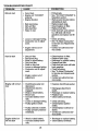
TROUBLESHOOTBNG CHART
......
PROBLEM
CORRECTION
CAUSE
'
Will not start
i,,i
ii, iii,
o Fill fuel tank.
o See %0 START ENGINE" in
Operation section.
o Wait several minutes before
attempting to start.
o Replace spark plug.
° Clean/replace air filter.
o Replace fuel filter.
o Drain fuel tank and carburetor, refilltank withfresh
gasoline and replace fuel filter.
o Check all wiring.
° See "To Adjust Carburetor"
in Service and Adjustments
section.
o Contact an authorized service center.
= Out of fuel.
,, Engine not "CHOKED"
properly.
• Engine flooded.
o
o
o
o
Bad spark plug.
Dirty air filter.
Dirty fuel filter.
Water in fuel.
o
Loose or damaged wiring.
Carburetor out of adjustment.
O
Engine valves out of
adjustment.
Hard to start
°
°
=
o
°
o
o
o
°
°
°
°
Clean/replace air filter.
Replace spark plug.
Recharge or replace battery.
Replace fuel filter.
Drain fuel tank and refillwith
fresh gasoline.
o Check all wiring.
o See 9"0 Adjust Carburetor"
in Service and Adjustments
section.
o Contact an authorized service center.
Dirty air filter.
Bad spark plug.
Weak or dead battery.
Dirty fuel filter,
Stale or dirty fuel,
Loose or damaged wiring.
Carburetor out of adjustment,
Engine valves out of
adjustment.
i
illlll
ill=l
Engine will notturn
over
° Clutch]brake pedal not
depressed.
,, Attachment clutch is
engaged.
o Weak or dead battery.
• Blownfuse.
o Corroded battery terminals.
° Loose or damaged widng.
,, Faulty ignitionswitch.
o
o
o
°
o Disengage attachment
clutch.
o Recharge or replace battery.
° Replace fuse.
° Clean battery terminals.
Faulty solenoid or starter.
Faulty operator presence
switch(es).
........
Engine clicks but
will not start
o Depress clutch/brake pedal.
Weak or dead battery.
Corroded battery terminals.
28
.....
=
° Check all wiring.
° Check/replace ignition
switch.
• Check/replace solenoidor
starter.
° Contact an authorized service center.
o Recharge or replace battery.
= Clean battery terminals.
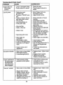
TROUBLESHOOTING
PROBLEM
-
Engine clicks but
will not start
(cont'd)
i ii,l,,
CHART
CAUSE
CORRECTRON
o Loose or damaged wiring.
o Faulty solenoid or starter.
o Check all wiring.
o Check/replace solenoid or
starter.
o Cutting too much
grass/too fast.
o Throttle in "CHOKE" position.
o Build-up of grass, leaves
and trash under mower.
o Set in "Higher Cut" position/reduce speed.
o Adjust throttle control.
ii,
Loss of power
o Dirt'y air filter.
° Low oil level/dirty oil.
° Faulty spark plug.
° Dirty fuel filter.
o Stale or dirty fuel.
Water in fuel.
o Spark plug wire loose.
• Dirty engine air
screen/fins.
o Dirtytclogged muffler.
o Loose or damaged wiring.
o Carburetor out of adjustment.
= Engine valves out of
adjustment.
Excessive vibration
o Worn, bent or loose blade.
° Bent blade mandrel.
o Loose/damaged part(s).
Clean underside
housing.
o Clean/replace air filter.
° Check oil level/change oil.
° Clean and regap or change
spark plug.
,, Replace fuel filter.
o Drain fuel tank and refill with
fresh gasoline.
° Drain fuel tank and carburetor, refill tank with fresh gasoline and replace fuel filter.
° Connect and tighten spark
plug wire.
o Clean engine air screen/fins.
o Clean/replace muffler.
o Check all wiring.
o See =ToAdjust Carburetor" in
Service and Adjustments
section.
o Contact an authorized service center.
o
o
°
Engine continues to
run when operator leaves seat
with attachment
clutch engaged
Poor cut - uneven
• Faulty operator-safety
presence control system.
Worn, bent or loose blade.
• Mower deck not level.
• Buildup of grass, leaves,
and trash under mower.
° Bent blade mandrel.
= Clogged mower deck vent
holes from buildup of
29
of mower
Replace
bolt.
Replace
Tighten
Replace
blade. Tighten blade
blade mandrel.
loose part(s).
damaged parts.
Check wiring, switches and
connections. If not
corrected, contact an authorized service center.
° Replace blade. Tighten blade
bolt.
° Level mower deck.
o Clean underside of mower
housing.
, Replace blade mandrel.
o Clean around mandrels to
open vent holes.
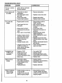
TROUBLESHOOTING CHART
PROBLEN
CAUSE
Poor cut- uneven
(cont'd)
Mower blades will
not rotate
,, ,,_
.............
CORRECTION
grass, leaves, and trash
around mandrels.
Obstruction in clutch
mechanism.
o Worn/damaged mower
drive belt.
o Frozen idler pulley.
o Frozen blade mandrel.
o Remove obstruction.
• Engine speed too slow.
o Place throttle controlin
"FAST' position.
o Shift to slower speed.
o Allow grass to dry before
mowing.
o Level mower deck.
, Check tires for proper air
pressure.
° Replace/sharpen blade.
Tighten blade bolt.
° Clean underside of mower
housing.
- Replace mower drive belt.
° Reinstall blades sharp edge
down.
o Replace with blades listed in
this manual.
° Clean around mandrelsto
open vent holes.
o Replace mower drive belt.
o Replace idler pulley.
o Replace blade mandrel.
,Jllll
Poor grass discharge
o Travel speed too fast.
o Wet grass.
,, Mower deck not level.
o Lowtuneven tire air pressure.
o Worn, bent or loose blade.
o Buildupof grass, leaves
and trash under mower.
• Mower drive belt worn.
o Blades improperly
installed.
o Improperblades used,
o Clogged mower deck vent
holes from buildup of
grass, leaves, and trash
around mandrels.
Headlight(s) not
working(if so
equipped)
°
o
°
o
o
Battery will not
charge
° Bad battery cell(s).
° Poor cable connections.
° Faulty regulator(if so
equipped).
° Faulty alternator.
Engine "bacldires"
when turning
engine "OFF'
o
Switch is"OFF".
Bulb(s) burned out.
Faulty lightswitch.
Loose or damaged wiring.
Blownfuse.
Engine throttlecontrolnot
set at "SLOW"
position for 30 seconds
before stopping engine.
3O
°
°
°
o
°
Turn switch "ON".
Replace bulb(s).
Check/replace light switch.
Checkwiringand connections.
Replace fuse.
° Replace battery.
° Check/clean all connections.
o Replace regulator.
° Replace alternator.
0
Move throttlecontrolto
"SLOW" positionand allow
to idlefor 30 seconds before
stoppingengine.
31
32
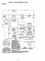
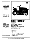
TRACTOR ,, = MODEL NUMBER 917o270510
SCHEMATIC
BLACK
BATTERY
I .....
AMMETER
,.
J. ....
, __: : I .......
I (OPTIONAL)
,,,,_-r",.._
i _.- p
k
_,
Mv
i |
IGNITION
in
j
,
_
CLUTCH / BP-,)_<E
_1
_
'_ l _
]_
J
SOLENOID
RED
.,.,.',
Bu___ji
_
i
|I
t
t
.
/_
I
;I "_-I-_,
"" I
,
..... I
I
(NOT OCCUPIED)
; r_._--_--_ i,i-
"3
L__._._,_.,o<
....
g
.
_I'"-HOUR-i.-.
-'
i"
(CLUTCH
OFF)
I
_'_l_'6"i'6F1
Ir---',J
SPARK
PLUG
GAP
i
(OPTIONAL)
....
,
SLU_
[
_
IGNITION
; - _.._E-LII
"-I
UNIT
II
...............
"_A" LINE iI
Su_
_
j
r,,
,_
............ ,_ )
_---"--'_
(2 PLUGS ON
TWIN CYL ENGINE,S)
BATTERY, BUT HAVE THEIR
OWN ELECTRICAL SOURCE.
BECAUSE OF THIS, THE
HEADUGHTS
BRIGHTNESS OF THE LIGHTS
WiLL CHANGE WITH ENGINE
SPEED. AT IDLE THE LIGHTS
._
WILL DIM. AS THE ENGINE IS
NON-REMOVABLE
REMOVABLE
CONNECTIONS
SPEEDED UP, THE LIGHTS
CONNECTIONS
WILL BECOME THEIR BRIGHTEST.
O
IGNITION SWITCH
WIRING INSULATED CLIPS
NOTE: IF WIRING INSULATED CLIPS WERE REMOVED FOR
SERVICING OF UNIT, THEY SHOULD BE REPLACED TO
PROPERLY SECURE YOUR WIRING.
33
.
/'77
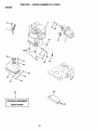
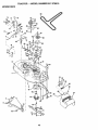
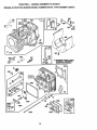
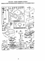
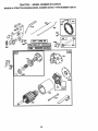
TRACTOR
- - MODEL NUMBER
917o270510
ELECTRICAL
1|
26
19
!
I
L ....
f
I
|
t
%
1
t
34
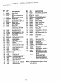
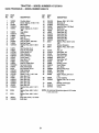
TRACTOR
== MODEL NUMBER
917.270510
ELECTRICAL
KEY
PART
NO.
NO.
1
2
3
4
6
8
16
19
20
21
22
24
25
26
28
29
30
31
32
33
40
41
42
43
44
45
52
70
NOTE:
144925
74760412
STD551025
STD551125
STD541025
156417
153664
STD551125
73350400
'136850
4152J
4799,,!
146147
108824X
4207J
121305X
140301
124211X
141226
109310X
156442
71110408
131563
145673
73640400
121€33X
141940
140422
DESCRIPTION
Battery12 Volt 25 AMP
Bolt Hex Hd 1/4-20uncX 314
Washer 9/32 X 5/8 X 16 Ga
Washer LockHvy Helical 114
Nut Fin Hex 1/4-20 Unc
Case Battery
SwitchInterlock Push-in
Washer Lock 1/4
Nut Jam Hex 1/4-20Unc
Harness SocketUght W/4152J
Bulb Light #t156
Cable Battery6ga 11"red
Cable Battery6 Ga W/16 Wir red
Fuse 30 AMP Auto Green
Cabte Ground6ga 12"black
SwitchPlunger Nc Gray
SwitchIgn 4 pos
Nut lgniUon
Cover Sw Ignition
Key lgn Molded Craftsman, Delta
Harness Man ClAm Hm 97
Bolt BIk Hex 1/4-20uncx 112
Cover Terminal Red
Sotenoid
Nut Keps BIk Hex 1/4-20Unc
Ammeter Rectangular6 AMP
ProtectionWire Loop
HarnessEngine,Dual14 OHV
All componentdimensions give in USo inches
1 tnch = 25.4 mm
35
TRACTOR
- - MODEL NUMBER
917.270510
CHASSIS AND ENCLOSURES
I7
21
26
31
29
14
i
28
26
33
10
14
3
36
TRACTOR
= = MODEL NUMBER
917,270510
CHASSIS AND ENCLOSURES
KEY
PART
NO.
NO.
1
2
3
4
5
6
7
8
9
10
11
13
14
15
't6
17
18
19
21
22
24
25
26
28
29
30
3t
33
34
35
37
38
39
54
100
140
145
-NOTE:
160393
140356
17490612
STD551025
155272
155924X015
126842X
155138
161914X012
STD533710
155927
155934X010
17490608
74180512
STD541431
154988X558
126938X
17521312
122933X
124479)(
STD5237t0
191313'12
STD541437
140137
124029)(
157584X558
136619
145244X558
145243X556
STD533707
17490508
139866
139887
161464
105037X
158418
156524
5479J
DESCRIPTION
Chassis
DrawbarStretch
ScrewThdrol3/8-16 x 3/4 Ty-tt
Washer13/32 X 314X 16 Ga
BumperDash Hood
SaddleStkscr
ShieldHL Hood Kohl/DiaEngine
ClipRetainerSlideOn
Dash Stkscrt-pc
BoltRdhdSqnk 3/8-t6unc X 1
Panel Dash LH
Panel Slk.scrDash RH
ScrewT'ndrot3/8-16 x 1/2 Ty-tt
ScrewMachTRHD 5/16-18 uncx 3/4
NutKeps5/16-18 Unc
HoodAsmPnt SlopeWeldMs-574
BumperHood
ScrewSltd Hex Hd W/PI Washer
RivetRatchetNylon
WasherNylonBIk28 x 75 x 19
BoltFinHex 3/8-16 uncx 1 Gro5
Washer13/32 X 13/16x 12 Ga
Nut Hex LockW/ins.318-16Unc
GrilleBlack
LensHeadlightBar Clear
FenderPntLT W/o Shift
BracketFender Rep1109873x
FootrestPntLh
FootrestPntRh
BoltRdhdSht Sqnk3/8-16 x 3/4
ScrewThdrot.5/16-18 x 1/2
BracketAsm Pvt LH MWR Rear
BracketAsm Pvt RH MWR Rear
ScrewHexWshd 8-t8 x 7/8
StripFoam18=
BracketSuspensionFront
RodPivotChassis/Hood
PlugButtonBIk359 Dia Choke
Allcomponentdimensionsgive in U,S. inches
1 inch= 25,4 mm
37
TRACTOR
= - MODEL HUMBER
917.270510
GROUND DRIVE
10
35
37
3
34
53
26
1
27
38
TRACTOR ,. = MODEL NUMBER 917.270510
GROUND DRIVE
KEY
NO.
PART
NO.
1
2
3
4
5
6
7
8
10
11
12
13
14
15
18
19
146682
123666X
12000028
121520X
17490512
162240
131679
STD561210
105701X
19151216
74550412
STD551!25
74490544
STD5237t0
STD541437
21
22
24
25
26
27
28
29
30
3t
32
34
35
36
37
38
39
40
41
106933X
130804
STD541237
I06688X
STD551037
STD561210
14-5204
124236X
130807
127275X
STD523107
155071
120183X
STD551062
STD571810
123674X
STD523727
4470J
154777
DESCRIPTION
KEY
NO.
Transaxle(See Breakdown)
Dana Mode! 4360-113
SpringReturnBrakeT/a Zinc
PulleyTransaxiet 8/20"tires
RingRetainer# 5100+62
StrapTorque30 Degrees
ScrewThdrol5/16-18 x 3/4 TYT
BracketSaddleShiftT/a
Rod Shf SdtLY/YT StrBIk Zinc
Pin Cotter1/8 x 1 Cad
WasherPlateShf388 Sq Hole
Washer15/32 x 3/4 x 16ga
Bolt1/4-28unfGr8W/Patch
WasherLockHvy Helical1/4
BoltHex FLGHD 5/16-18Gr+5
Bolt Fin Hex
Nut LockHexW/tns_ 3/8-16
Unc
KnobRd 1/2-13PlstcThdsBIk
RodBrake BIkZinc26 840
Nut Hex Jam3/8-16 Unc
SpringRodBrake2 00 Zinc
Washer13132x 13116x 16 Ga
Pin Cotter1/8x 314Cad
Rod BrakeParking Lt/Yt
Cap Brake PartdngRed
BracketMtgTransaxle
KeeperBelt LH LT 14 Ga
Bolt Hex Hd 5/16_t6uncx 3/4
ShaftAsm Pedal Foot
BearingNylon Bik 629 ld
Washer21/32 x I x 16 Ga
Pin Roll 3/16 x 1"
PulleyIdlerFlat
BoltFin Hex3/8-16unc x 2-314
SpacerSplit395 x 59 Bzp
KeeperBeltIdler
42
47
48
49
50
51
52
53
55
55
57
58
59
61
62
63
19131312
127783
154407
123205X
STD523715
STD541437
STD541431
105710)(
105709X
STD523712
130801
127274X
140312
17490612
8883R
140186
64
65
66
70
72
74
75
76
77
78
112
116
71170764
STD551143
154778
134683
19132012
1095O2)(
121749X
STD581075
123583X
121748)(
19091210
72110610
145
149
150
151
159103
122052X
150935
19'I33210
NOTE:
39
PART
NO.
DESCRiPTiON
Washer13/32 x 13116x 12 Ga
Pulley idlerV Groove Plastic
Bellcrank ClutchGm Dry StJ
RetainerBelt Style Spring
BoltHex Hd 3/8-t6unc x 1-1/2
Nut Crownlook3/8-16 UNC
Nut CrownLock5/16-18
LinkCIutch7 66
SpringReturnClutch6 75
BoltFin Hex318-!6 unc x 1-114
V-BeltGd Drive95 25
KeeperBelt RH LT PnVzinc 16g
KeeperBelt Centerspan
ScrewTndrel3/8+16 x 3/4 Ty-tt
Cover Pedal BlkRound
PulleyEngCI Mech38deg
LT/'(T
BoltHex 7/16-20 x 4 Gr 5
Washer LockHvy HlclSpr 7/16
Keeper Belt Engine
GuideBeltMowerDriveRH
Washer 13132x 1+1/4x 12 Ga
SpacerAxte
Washer25132x I 1/4 x 16 Ga
E-ring#5t 33-75
Key Square2 0 x 1845/1865
Washer25/32 x 1-5/8 x 16ga
Washer9/32 x 3/4 x 10 Ga
BoltRdhdSq Neck3/8-16 x
1°25
Spacer
Spacer RetainerPM Mower
BushingNylonColiered
Washer t3/32 x 2 x 10 Ga
All componentdimensions give in US.
inches 1 inch = 25,4 mm
TRACTOR
= .. MODEL NUMBER
917o270510
STEERING ASSEMBLY
L
'
t."
.x
t
z;t
7
18
13
11
4O
\
\
4O
28
10
4O
TRACTOR ° - MODEL NUMBER
917,270510
STEERING ASSEMBLY
KEY
NO.
1
2
3
4
5
6
7
8
9
10
1'1
13
15
17
18
19
20
22
23
25
26
27
28
29
30
32
36
37
36
39
40
41
42
43
46
47
62
65
66
67
68
PART
NO.
139768
154427
156483
157473
6266H
121748X
19272016
12000029
3366R
156438
10040600
154779
73901000
156545
57079
124035X
126684X
71200410
t27501
154406
126847X
136874
19131416
17490612
STD561210
130465
155099
152927
139769
19133808
STD541537
104820X
124417)(
121749X
121232X
6855M
156593
154780
154404
74781044
154429
DESCRIPTmON
Wheel Steering Opp Sears BIk
AxleAsm Front Lt
SpindleAsm Lh
SpindleAsmRh
WasherThrust ,75x 1.230
Washer 25/32 x 1-5/8 x 16 Ga.
Washer 27t32 x 1-1/4 x 16 Ga,,
RingKlip#'i"5304-75
BearingCotStrg BIk
Dragiink ExtendedStamped
WasherLockHvy HlclSpr 3/8
BearingAxle
LocknutRange 5/8-1t UNC
ShaftAsmStrg 5/8 x t5.19 Lt
WasherThrust o515x .750 x °033
SupportShaft
WasherShim 1/4 x 5/8 x .062
ScrewHex Socket1/4-20x 5/6
ShaftAsm Pitman
BracketSteering
BushingUnk DragBIk LR
Gear Sector22 Teeth
Washer I3/32 x 7/8 x 16 Ga°
ScrewT'ndrol3/8-16 x 3/4 TY-TT
Pin Cotter 1/8 x 3/4 Cad
RodTieWire Form 19,75 Mech
BushingStrg. 5/8 ID Dash
Screw
Cap Wheel Steer Opp SearsUSA
Washer 13/32 x 2-318x 8 Ga.
LocknutCenter 3/8-24 Unf
AdaptorWheel Strg..640/.635 td
BootShaftSteeringCraftsman
Washer 25/32 x 1-1/4 x 16 Gao
Cap SpindleFr TopBik
FittingGrease
SteeringAssembly
SpacerA.vJe
BearingArm Pittman
BoltRn Hex 5/8-tl UNC x 2-3/4
BraceAxle
NOTE: Allcomponentdimensionsgivenin U,S. inches
1 inch= 25,4 mm
41
TRACTOR = ,, MODEL NUMBER 917.270510
ENGINE
81
44
38
78
33
31
40
23
29
OPTIONAL
/
EQUIPMENT
Spark Arrester
42
TRACTOR
= = MODEL NUMBER
917,27051(}
ENGINE
KEY
NO.
t
2
3
4
13
14
15
16
23
29
31
32
33
35
37
38
40
44
46
62
72
78
81
PART
NO.
162144
17720410
137352
272293
13280324
13200300
STD551237
159880
137180
109202X
158990
t23487X
17490512
137040
124028X
t7490412
19091416
STD551131
71070512
17490620
128861
DESCRIPTION
Control_h/ch RH BIk Pdt 15 10
ScrewHexThd Cut 1/4-20x5/8T
Engine (See Breakdown)B_ggs
Model No 287707-1255-Et
Muffler Exh LT B&S 14HP IC OHV
Gasket Eng 1 313 ld Tin Plated
Nipple Pipe 3/8 Npt x 3"
ElbowStd 90 Degree 3/8-18 Npt
Washer Lock Ext Tooth 3/8
Shield Browning!Debris Guard
Kit SparkArrestor (Flat Scm)
Tank Fuel Front I 25
Cap Asm Fuel Sears Vented
Clamp Hose Blk
ScrewThdrol5/16_t8 x 3/4 TYT
Une Fuel20"
PlugOil Drain(Order FromEngineManufacturer)
BushingSnap Nyl Blk Fuel Line
ScrewHexwshThdrot1/4-20 x 3/4
Washer9/32 x 7/8 x 16 ga
WasherLock HvyHtc{Spr 5/t6
ScrewHex Hd Cap 5/16-18 X 3/4
ScrewThdro! 3/8-16x1-1/4TYTT
Nut Flange t/4-20 Starter Nut
NOTE: All componentdimensions given in UoS.inches
1 inch= 25.4 mm
43
TRACTOR
,,., MODEL NUMBER
917.270510
SEAT ASSEMBLY
12
KEY
NO.
1
2
3
4
5
6
7
8
9
lO
11
12
PART
NO.
1401_
140551
ST0523710
19131610
145006
STD541437
124181X
17490616
19131614
155925
12OO68)(
121246X
DESCRIPTION
Seat
Bracket Pvt St
BoltFin Hex 3/8-16uncX 1
WasherRat 13/32X 1 X 10 Ga
Clip Push-InHinged
LocknutHex W/Wsh 3/8-16
SpringSeat Cprsn2 250 Bik23
ScrewThdrol3/6-16 X 1 Ty-tt
Washer 13/32X 1 X 14 Ga
Pan Seat
KnobSeat 1/2-,13Unc BIk
BracketMountingSwitch
KEY
PART
NO.
NO.
13
14
15
16
17
21
22
24
25
121248X
72050412
134300
121250)(
123976)(
153236
STD541431
19171912
127016X
DESCRIPTION
BushingSnap Bik Ny150 Id
BoltRdhdSht Nk 1/4-20x1-1/2
Spacer Split28x 96 Yel Zlnc
SpringCprsn1 27 BlkPnt
Nut Lock 1/4 Lge Rg Gr 5 Zinc
BoltShld5/16-18 Uric
Nut LockHex'W/Ins 5/16-18
Washer17/32 X 1-3/16X 12 Ga
BoltShoulder5/16-18 X 62
NOTE: All componentdimensions g_venin U,S_inches
1 inch= 25,4 mm
44
TRACTOR
-" MODEL NUMBER
9! 7.270510
DECALS
14
6
4
16
14
11
\
21
16
10
9
\
12
13
15
18
KEY
NO.
PART
NO.
1
2
3
4
6
1_8_
_3511
1_9_
1_991
133644
9
10
1_2_
149516
11
12
156439
4_OJ
WHEELS
KEY
NO.
DESCRIPTION
13
14
t5
16
21
Decal Dash InstOper English
Decal HP Engine
Decal Hood RH
Decal Hood LH
Decal Maint Oust Sears
Domestt
Decal FenderCraftsman White
Decal BatteryDngr/Psn Eng
Acme
Decal Danger Fender Eng/span
Decal Clutch/brakeEnglish
PART
NO.
146046
163249
160396
163209
131265
133179
'157119
138311
162914
162915
DESCRIPTION
Decal V-Belt Dr SchTractor
Decal Panel Dash 6sp 42"
Decal V-Belt Sch
Decal Fender Sd 6/42
DecalLightbox
Decal Mower QC System
Pad Footrest
Decal Handle Lft Height Adjust
Manual Owners English
Manual Owners Spanish
& TIRES
KEY
NO.
1
2
3
4
5
6
7
6
9
10
11
4.1o
,9
11
PART
NO.
59192
65139
106222X
59904
106732X427
276H
9040H
106108X427
124635)(
7152J
104757X
144334
DESCRIPTION
Cap ValueTire
Stem Value
Tim FTs 15X60 -6 Service
Tube InnerFront#35060
RimAsm6"frontWhiteService
Fitting Grease
Bearing Flange
RimAsm 8"rearWhite Service
Tire RTs 18x9 5-8 Service
Tube Rear 9 5 X 8 Service
Cap Axle BIk 1 50 X 1 00
Sealant,Tire (10 oz. tube)
NOTE: All componentdimensions given in U°Soinches
1 inch = 25A mm
45
TRACTOR
- = MODEL
NUMBER
917o270519
LiFT ASSEMBLY
8
,f
/
/
/
f
!
5
13
,\
4
11
I'
/
3
5
13
19
13
20
i
32
19
32
46
TRACTOR
- - MODEL NUiVlBE_
LiFT ASSEMBLY
KEY
NO.
1
2
3
4
5
6
7
8
'11
12
13
15
16
17
18
19
20
31
32
PART
NO.
DESCRIPTION
159460
159474
105767X
Wire Asm Inner/Sprg W/plunger LT
Shaft Asm Uft
Pin Groove 1 500 Zinc
12000002
19211621
120183X
125631X
1_365X
139865
139866
STD624008
127218
73350800
130171
73800800
139868
STD624008
140302
73540600
E Ring #5133-62
Washer Pltd 21/32 X 1 X 21ga
Beating Nylon BIk 629 Id
Grip Handle Fluted BIk
Button Plunger Red
Link Lift LH
Unk Lift RH
Retainer Spring
Link Front
Nut Jam Hex 1/2-13 Unc
Trunnion BIk Zinc
Nut Lock W/wsh 1/2-13unc
Arm Suspension Rear
Retainer Spring Zinc
Bearing Pvt Lift Spherical
Nut Crownlock 3/8-24
NOTE: All component dimensions given in U_S.inches
1 inch= 25A mm
47
TRACTOR
-- MODEL NUMBER
917,270510
MOWER DECK
68
76
77
_"'40
74
73
71
34
,33
32
31
58
17
\
i
1
\
2
16
29
18
48
27
TRACTOR
= - MODEL NUMBER
917,270510
MOWER DECK
KEY
NO.
PART
NO.
1
2
3
144393
STD533107
138017
4
5
6
8
9
10
11
12
13
138440
STD624008
130832
850857
STD551137
140296
134149
129895
137645
14
15
16
17
18
t9
20
21
22
23
24
25
26
27
28
29
30
31
32
33
34
35
36
37
40
4t
43
44
45
46
48
128774
110485X
140329
72110610
72140505
132827
159770
STD541431
t34753
131267
105304X
123713X
110452)(
130968
19111016
131491
157722
129963
153535
t37266
STD633717
133835
131494
19131316
STD641437
133551
140083
140088
STD624003
137729
133944
KEY
NO.
DESCRIPTION
MowerHousing
Bolt
BracketAssembly,
Sway Bar,
Front
BracketAssembly, Sway Bar
RetainerSpring
Arm,Suspension,Rear
Bolt,Hex 3/8-24 x 1.25 Gr.8
Washer,Lock
Washer,Hardened
Blade,Mulching
Bearing,Ball
ShaftAssembly,Mandrel,
Vented(includesKey No. 6)
Housing,Mandrel,Vented
Beadng,Ball, Mandrel
Stripper,VentedMowerDeck
Bolt,Carriage 3/8-16 x 1_1/4
Bolt, Carriage 5!16-18 x 5/8
Bolt,Shoulder
Baffle,Vortex
Nut Cmwniock5/16-18 UNC
StiffenerBracket
Bracket,Deflector
Cap, Sleeve
Spring,Tomion,Deflector
Nut, Push
Shleld,Deflector
Washer 11/32x 5/8 x 16 Ca.
Rod, Hinge
ScrewThdrolWasherHead
Washer,Spacer
Pulley,Mandrel
Nut, Toplock,Ranged
Bolt
Fastner,ChristmasTree
Pulley,Idter,Rat
Washer 13/32 x 13/t6 x i6 Ca,
Nut Crownlock3/8-16 UNC
Rod,Pivot, with Nibs
Rod,Clutch,Secondary,w/Nibs
Guard,Mandrel, LHo
Retainer
Screw,Thd. Roll 114-20x 5/8
Washer,Hardened
PART
NO.
49
50
51
52
53
54
55
56
58
59
67
68
71
72
73
74
75
76
155066
131340
STD541410
139888
131845)(900
133943
155046
122052X
140086
141043
162113
144200
142427
131870
127847
121748)(
12000029
128903
77
78
127845
160571
79
80
81
82
83
64
85
92
128
132
t27498
153701
73350600
142028
120958)(
156084
72140618
STD541437
153390
19132203
141
--
6266t--i
130794
-*
145411
DESCRIPTION
RollerAssembly,Cam Follower
Bolt, Shoulder #10-24 Grade5
Locknut
Bolt,Shoulder 5/16-18 UNC
ArmAssembly, Pad, Brake
Washer,Hardened
Arm,Idler
Spacer,Retainer
Spring,TorsionBrakes
Guard,TUV Idler
KnobCustomOval
V-Belt
Rod,Clutch,Primary,withNibs
Spring,Return
Arm, Clutch,Secondary
Washer 25/32 x 1-5/8 x 16 Ga.
Ring, K]ip
Bolt, Shoulder 3/8-16 UNC x
1o44
Keeper, Spring
LeverAsm. ClutchPfi PIm
STLT
Bushing, Large, Brass
Spring, Mower Clutch
Nut, HexJam 3/8-t6 Unc
*-Trunnion,Adj_
Washer Stntered
Keeper Belt Idler
Bolt Carriage 3/8-16 x 2-1/4
Nut
Washer Felt
Spacer,Washer 13/32 LDox 13/80.D. x 1/4
Washer Thrsut .75 x 1.230
MandrelAssembly (Includes
Key Numbers 8-10, 12-15,31
and 32)
Mower Deck, Complete
(Standard Deck, Order
SeparatelyMulcher Plate and
Gauge Wheel Components,
Key Nos. 101-106 and 111-121)
NOTE: Allcomponentdimensions givenin U.SJnches
I inch= 25.4 mm
49
TRACTOR
,.., MODEL HUIVIBER 917.270510
DANA TRANSAXLE =° MODEL NUMBER 4360-113
20
21
22
8
25
31
27
I0
11o
53
45
48
57
49
59
62
61
7O
50
TRACTOR .- - MODEL NUMBER
917.270510
DANA TRANSAXLE - .. MODEL NUMBER 4360-113
KEY
NO.
PART
NO.
1
2
3
4
5
'!60939
2274J
134400
105904X
160940
6
7
8
9
10
11
12
13
138235
108727)(
148266
148269
2225J
134793"
148268
120415)(
t4
15
16
17
18
19
20
21
22
23
24
25
26
27
28
29
30
31
32
33
34
35
142674
138234
110078X
105909)(
105910)(
160942
160943
148267
138236
73810500
142676
2244J
105916X
120470X
110070X
142677
142681
t24644X
108980)(
120406)(
134796
!05925X
36
2228J
37
2231J
38
39
160944
124639X
KEY
NO.
DESCRIPTION
Housing,Upper
Screw,Tapping,1/4-20 X 4734
Ball, Detent
Spring,Detent
Screw,Tapping, No. 10_24X
.482
Assy, Shifter
V-Ring
Bearing,Flange
SeaS,Oil
Ring, Retaining
Assy, Kit, Shim,.625 Shaft
Bearing, Range
Washer,Plain, .632X 1.38X
.046
Key,Woodruff,No.9
Assy,Kit,tnputShaft
Pinion,Bevel,14T
Ring,Retaining
Chain,24 Pitches
Cover, Detent
Gear,Spur, 12T
Collar,Clutch
Assy,Kit,ClutchKeys
Nut,Lock,5/16-24
Shaft, Intermediate
Key,Woodruff,No. 6t
Ring,Retaining
Sprocket,18T
Spacer,1.131 X 1o45X .494
Gear, Spur,371"
Gear, Spur,35T
Gear, Spur,30T
Gear, Spur, 25T
Gear, Spur,22T
Gear, Spur191"
Washer, Plain,°640X 1.37 X
.061
Washer,Plain, .632X 1.00 X
.046
Washer,Plain,.632 X 1.00 X
,031
AsE:/,Gear,Comb., 12T& 30T
Shaft,idler
PART
NO.
40
41
42
43
44
45
46
47
48
49
50
51
120472X
t05928X
110084X
134394*
!20473X
142678
143697
124641X
t06589X
t20406X
105937X
2226J
52
53
134401
2264J
54
55
56
57
56
59
60
6t
62
63
64
65
66
67
160946
tt0081X
160948
!10071X
120952X
110082X
160950
142680
120961X
7294J
108989X
160952
120954X
160953
68
69
136244
108996X
70
71
72
160954
120951X
120416X
DESCRIPTION
Spacer,.633 X .87 X _755
Sprocket,9T
Gear, Bevel,42"I"
Assy, Kit, Shim, .750 Shaft
Shaft,Drive
Gear, Spur,12T
Gear,Spur, 151"
Gear,Spur,20T
Gear, Spur,25T
Gear,Spur,28"i"
Gear,Spur,31T
Washer,Plain, .632X 1.00 X
.060
W'asher,Neoprene
Washer,Plain, .758)( 1.25X
.031
Axle,LH
Gear, Miter,15T
Ring,Retaining
Gear, Spur,32T
Shaft,Cross
Gear, Miter,15T
Axle, RH
Houstng,Lower
Puck, Friction
Disc,Brake
.Spacer,Brake Puck
Jaw, Brake
Pin, Dowel
Screw,Tapping,5/16-18 X
2.35
Lever,Actuating
Washer,Plain, .32! X 1o00X
.055
Bracket,Anti-Rotation
Puck,Fdctlon
Grease
NOTE: Allcomponentdimensions givenin U.S. inches
1 inch= 25_4mm
51
TRACTOR
- - MODEL NUIVIBER 917.270510
BRBGGS& STRATTON ENGINE-MODEL NUMBER 287707, TYPE NUMBER 1255-E1
230
3
_614
11
@
634A
REQUIRES SPECIAL TOOLS
TO INSTALL SEE REPAIR
INSTRUCTION MANUAL
1022
4O
4O
7
868A
868
52
166
1034
1029
1026
52
TRACTOR =,, MODEL NUMBER 917.270519
BRIGGS
& STRATTON
ENGINE-MODEL
NUMBER
287707, TYPE NUMBER
1255-E1
24
46
15
52
127
9
164
_123
1_ REQUIRES SPECIALTOOLS
TO INSTALL SEE REPAIR
INSTRUCTION MANUAL
51A_
.Ise
LMT NUMBEB
53
142
TRACTOR
,- = MODEL NUMBER
917.270510
BRIGGS & STRATTON EHGIHE-IVtODEL HUMBER 287707, TYPE NUMBER 1255-E1
3
872
171
535
9
,,,i,ii ,,,i
524
305
668
224
30_]
_78
73
646
1006
i,i
illlllllll,
188
_
54
TRACTOR = o MODEL HUMBER 917.270510
BRIGGS & STRATTON ENGIHE-MODEL NUMBER 287707, TYPE NUMBER 1255-E1
201
663
265
iio',="_=1
209
783
729
_J
615
1090
311
803
55
TRACTOR
..- MODEL
NUMBER 9!7.270510
BRIGGS & STRATTON ENGINE-MODEL NUMBER 287707, TYPE NUMBER 1255-E!
KEY
NO.
PART
NO.
1
2
3
4
5
7
8
9
10
11
12
496412
399265
391086
494238
495858
272614
495735
27803
94621
281246
271916
271997
271996
13
15
16
20
22
23
24
25
94728
94239
495162
94196
291675
94624
492326
222698
495860
495977
495978
495979
26
27
28
29
495854
495852
495851
495855
263129
498319
494504
495490
32
94695
32A
94646
33
34
35
37
40
45
46
51
495856
495857
262811
224502
224641
262411
496884
272465
52
272569
KEY
NO.
PART
NO.
Cylinder Assembly
Bearing, Cylinder
*Seal, Oil
Base, Engine
Head, Cylinder
***Gasket, Cylinder Head
Breather Assembly
*Gasket, Valve Cover
Screw, Sems
Tube, Breather
*Gasket, Crankcase Cover,
1/64"
*Gasket, Crankcase Cover,
_005"
*Gasket, Crankcase Cover,
..009"
53
73
75
78
93
95
98
104
105
I06
108
111
1t7
118
t21
94637
224948
225136
94626
281346
94098
495800
231789
231855
231854
224540
262719
232118
232119
498030
499233
Stud, Carburetor Mounting
Screen, Flush Rotating
Washer, Spring
Screw, Sems
Bushing, Throttle Shaft
**Screw, Throttle
Screw, Idle Speed
**Pin, Float Hinge
"*Valve Float
**Seat, Inlet Valve
Valve, Choke
Spring, Choke
Jet, Main (Std.)
Jet, Main (Hi-AlL)
Vah,e, Needle
Carburetor Overhaul Kit
Screw, Cylinder Head
Plug, Ot_ Drain
Crankshaft
Timing Gear Key
*Seal, Oil
Screw, Seres, Base Mounting
Flywheel and Ring Gear
Assembly, Magneto
Key, Flywhee!
Piston Assembly, Standard Size
Piston Assembly, ,810"
Oversize
Piston Assembly, °020"
Oversize
Piston Assembly, .030"
Oversize
Ring Set, Piston, Standard Size
Ring Set, Piston, ,,010"Oversize
Ring Set, Piston, .020" Oversize
Ring Set, Piston, ..030" Oversize
Lock, Piston Pin
Pin Assy,, Piston, Standard Size
Rod Assembly, Connecting
Rod Assembly, Connecting,
;020" Undersize Crankpin Bore
Screw, Hex Washer Head, 157/64
Screw, Hex Washer Head, 1_
518
Vatve, Exhaust
Valve, intake
Spring, Valve
Guard, Flywheel
Retainer, Valve Spring
Tappet, Valve
Gear, Cam
****Gasket, Carburetor
(Carburetor to Elbow)
**'Gasket, Carburetor
(Elbow tO Cylinder)
123
125
127
130
131
133
137
138
141
142
94913
499153
--224539
494379
494381
281 I65
281164
495931
232117
Screw, Elbow Mounting
Carburetor Assembly
**Plug, Welch (Sold in Kit Only)
Valve, Throttle
Shaft and Lever, Throttle
Float, Carburetor
**'Gasket, Float Bowl
****Washer, Bowl
Shaft and Lever, Choke
Nozzle, Carburetor
t64
166
171
!87
214047
94555
28105t
492790
Elbow, Carburetor
Stud, Rocker Arm
Nut, Air Cleaner Mounting
Une, Fuel (t t" Long, Cut to
188
192
20t
209
216
219
222
224
25
227
230
232
238
240
265
NOTE:
94627
Screw, Hex Head, 3/4
492t60
Screw Assembly, Rocker Arm
262767
Unk, Governor
260695
Spring, Govemor
262766
Unk, Choke
490815
Gear, Governor
4956tl
Plate, Governor Contro_
94729
Screw, Sems, Air Cleaner
495157
Crank, Governor
493935
Lever Assembly, Governor
94927
Washer, Governor Crank
262785
Spring, Govemor Link
262836
Cap, Valve
394358
Filter, Fuel (In Fuel Line)
221535
Clamp, Casing
All component dimensions given in U..S_inches
1 inch = 25.4 mm
Included In Gasket Set (495993)
Included In Carburetor Kit (499233)
Included In Both Gasket Set (495993) and
Valve Overhaul Kit (495992)
Included In Gasket Set (495993), Carburetor Kit
(499233) and Carburetor Gasket Set (494385)
DESCRIPTION
DESCRIPTION
Suit)
*
**
***
***"
56
TRACTOR
= = MODEL HUMBER
917.270510
BRIGGS & STRATTON ENGINE-MODEL NUMBER 287707, TYPE HUMBER 1255-E1
KEY
PART
NO.
NO.
284
294
304
305
94704
810068
496318
94786
306
307
309
310
311
333
334
225020
94930
497595
497602
497608
495859
94731
337
346
356
356A
356B
358
363
383
423
445
455
467
474
482
510
523
524
525
535
537
544
552
562
592
601
611
614
615
634
634A
635
646
657
663
668
718
726
491055
93705
497708
497671
494705
495993
19203
89838
94903
496894
222561
493903
393474
93621
497606
495230
281370
496113
272403
281106
497603
231597
94907
231978
93053
493496
93306
263080
494455
491323
280872
224546
94906
94929
280848
230192
892134
_7
_8
_9
4903_
9_51
2251_
DESCRIPTION
Screw,Hex Head
Screw,Set
Housing,Blower
Screw,Hex, Head,
BlowerHousingMounting
Shield,Cylinder
Screw,CylinderShield
Motor,Starter
Bolt,ThnJ
BrushSet
Armature,Magneto
Screw,Seres,Armature
Mounting
Plug,Spark
Screw, Hex Head
WireAssembly
Wire, Stop
Wire Stop
GasketSet
Puller, Rywheet
Wrench,SparkPlug
Screw,Seres
Cartridge,AirCleaner
Cup, ScreenMounting
Knob,AirCleaner
Stator,Alternator
Screw,Sems
Drive,Starter
Cap and Dipstick,Oil Filler
"Seal, FillerTube
Tube, Oil Filler
Element,Filter
*O-Ring,Air Cleaner
Armature,Starter
Bushing,GovernorCrank
Bolt,GovernorLever
Nut,Hex
Clamp, FuelPipe
Elbow,Fuel Pipe
Pin,Cotter
Retainer
**Seal, ChokeShaft
*Sea!, Governor
Elbow,Spar',(Ptug
Brace,Air Cleaner
Screw,Seres
Screw,Self-Tapping
Spacer
Pin,Dowel
Gear, Ring
(IncludesMountingHardware)
Cover,Starter
Screw,Hex Head
Retainer,Wire
KEY
PART
NO.
NO.
DESCRiPTiON
Clip, Wire
Gear, 3qming
Unk, Counterweight
Counterweight Assembly
Pin, Counterwelght
Screw, Counterweight
Gear, Starter
Cap, Drive
Cap, End
Housing,Starter
"
Seal, Oil FillerCap
FillGroup,Oil
Terminal,IgnitionCable
***
Seal,_sembly,
Valve
***
Gasket,Valve
868A 272610
Bushing,Guide
(Intake &
871
262835
Exhaust)
Cover, Air Cleaner
872
281104
Body,Air Cleaner
875
495862
Diode and Connector Assembly
877
393456
Solenoid
947
497672
NUt, Hex
965
94108
BowlAssembly,Carburetor
975
495933
CarburetorGasketSet
977
494385
**
Seal, ThrottleShaft
987
281166
Fan, Rywheel
1005 280687
Retainer,Fan
1006
224413
Label
Kit
1019
496758
***
Gasket,Cover
1022
272475
Cover, RockerArm
1023
224552
Rod, Push, Intake
1026
494432
Rod, Push, Exhaust
495136
Ann, Rocker
t029
224554
Valve Overhaul Kit
1033
495992
Guide Assembly, Push Rod
1034
495248
Label Kit, Emissions
1036
499364
Screw, Hex Head
1044
94673
Extension,Crankshaft
1045
231828
Manual, OwnerOs
i058
272623
Retainer,Brush
1090
497607
Cap,
Umiter
1091
281364
2500
28N707-1026 ReplacementEngine
ReplacementShortblock
--,-496050
Low:.1650-1850, High:3200RPM Settings:
340O
NOTE: A!l componentdimensionsgiven In UoS.inches
1 inch= 25.4 mm
"
IncludedIn Gasket Set (495993)
**
Includedin CarburetorKit (499233)
***
Included In BothGasket Set (495993) and
ValveOverhaulKit (495992)
****
IncludedIn GasketSet (495993), CarburetorKit
(499233) and CarburetorGasketSet (494385)
729A
741
757
758
759
761
783
801
802
803
842
847
851
868
57
281390
262932
213998
39989I
298909
94593
280104
394856
497605
497604
270920
496415
493880
494435
58
SUGGESTED
GUIDE FOR SIGHTING SLOPES FOR SAFE OPERATION
ONLY RIDE UP AND DOWN HILL,
NOT ACROSS HILL
SIGHT AND HOLD THIS LEVEL WITH
SKY LINE OR TREE.
o'!
_o
15 ° MAX.
|
d
A
U _
n _
Operate your Tractor up and down the face of slopes (not
greater than 15°), never across the face. Make turns gradually to prevent tipping or loss of control. Exercise extreme
caution when changing direction on slopes.
I
For the repair or replacement parts you need
delivered directly to your home
Call 7 am - 7 pm, 7 days a week
I =800=366=PART
(1-800-366-7278)
Para ordenar piezas con entrega a
domicilio - 1-800-659-7084
For in-house major brand repair service
Call 24 hours a day, 7 days a week
1=800-4-REPAIR
(1-800-473-7274)
Para pedir ser¢icio de reparaci6n
domicilio - 1-800-676-58t 1
a
For the location of a Sears Parts and
Repair Center in your area
Call 24 hours a day, 7 days a week
1=800-488=1222
For information on purchasing a Sears
Maintenance Agreement or to inquire
about an existing Agreement
Call 9 am - 5 pm, Monday-Saturday
1=800=827-6655
When requesting service or ordering
parts, always provide the following
information:
- Product Type
o Part Number
° Model Number o Part Description
America's
162914
Rev. 4
3.30.98
RH/'rR/JH
Repair Specialists
Printed in U.S.A.