1
2 - 36
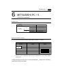
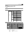
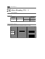
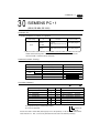
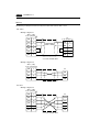
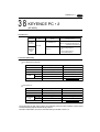
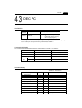
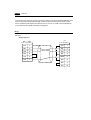
2 HITACHI PC • 1
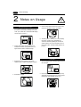
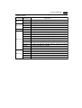
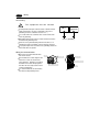
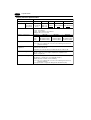
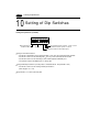
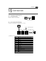
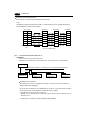
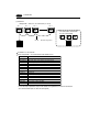
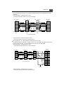
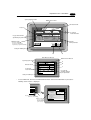
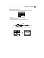
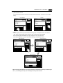
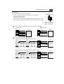
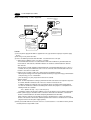
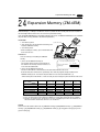
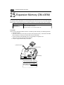
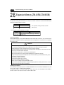
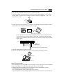
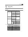
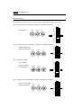
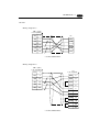
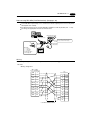
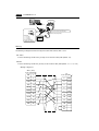
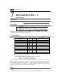
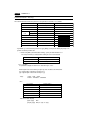
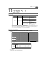
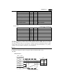
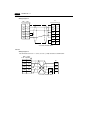
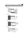
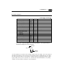
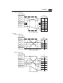
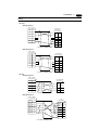
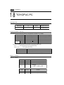
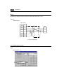
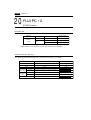
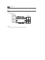
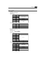
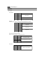
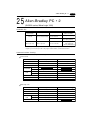
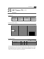
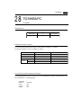
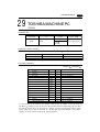
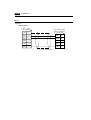
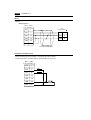
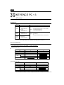
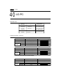
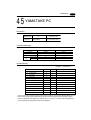
Switch Setting
Baud rate
MODE switch
: 19200bps
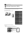
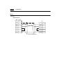
: To connect to both RS-232C and RS-422, set MODE switch to 9.
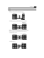
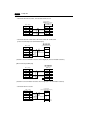
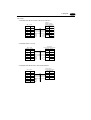
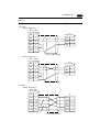
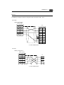
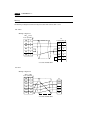
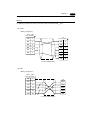
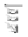
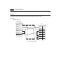
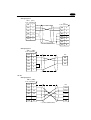
RS-232C(pattern 2, w/o)
RS-422(pattern 2, with port)
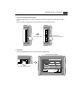
ST No. switch : Choose "0" for both X10 and X1.
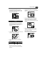
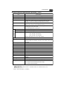
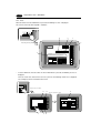
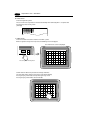
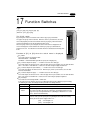
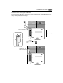
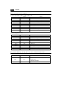
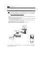
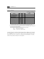
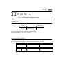
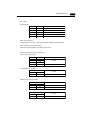
Dip Switch
Switch
Setting
Contents
1
OFF
Bit length
2
OFF
3
ON
4
ON
5
ON
Parity provided
6
ON
Even
7
OFF
Stop bit 1
8
ON
Sumcheck provided
Same as ZM-**
(normally 19200bps)
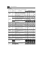
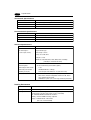
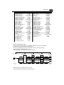
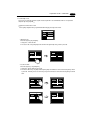
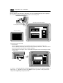
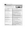
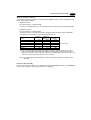
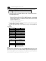
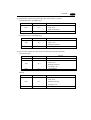
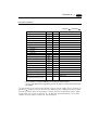
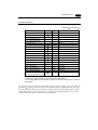
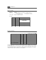
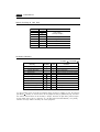
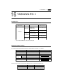
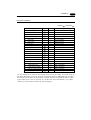
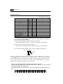
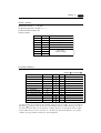
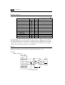
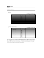
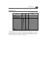
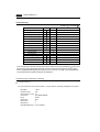
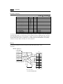
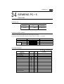
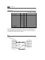
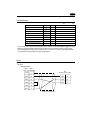
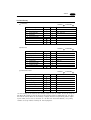
Available Memory
Available:
Memory
Bit Write
TYPE
WR (internal word output)
0
X
1
(external bit input)
Unavailable:
Remarks
WX as word device
Y
(external bit output)
2
WY as word device
L
(bit CPU link area)
3
WL as word device
M
(bit data area)
4
WM as word device
TC
(timer counter/elapsed time)
5
R
(relay)
6
TD
(timer/counter [contact])
7
WN
(network input/output)
8
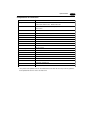
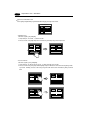
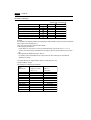
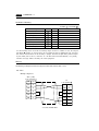
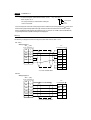
Set the memory to the extent of the memory range of each PC model. In case of using the
[Bit Write]
memory as the bit device of the [Output Action] is [Momentary W], the other
bits will be cleared when the bit memory is output, because the [Bit Write] will be output
by one word (refer to P5-10, reference 14-7 of ZM-71SE Instruction Manual). Use [TYPE]
number to assign indirect memory for macro programs.