1
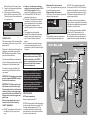
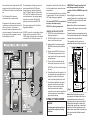
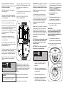
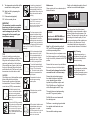
1
Before telephoning the Creda Technical Hotline you should
ensure that you have the model number, power rating,
serial number and date of purchase.
4
A charge will be made where a call under the terms of the
guarantee has been booked and a failure was not product
related, or an engineer arrives and is not able to gain access.
5
If the product is no longer covered by the Guarantee, a charge
will be made for the site visit and for any parts supplied.
3
1
FLOW
+
+
STOP/START
6
5
4
1
Technical Hotline
2
7
9
3
If a service call is booked, you or a representative must be
present during the Engineers visit.
4
2
The Creda Technical Hotline will be able to inform you whether
the fault can be rectified by the provision of a replacement part
or an on site visit by a Qualified Service Engineer.
5
6
3
2
Creda
7
In the event of you needing to contact the Creda Technical Hotline, the
following procedure should be followed:-
Thermostatic Power Shower
Installation Instructions
8
SERVICE POLICY
TEMPERATURE
Telephone: 08709 000430 Fax: 08709 000530
Email: [email protected]
9.00 am - 5.00 pm Monday to Friday
11/2008
IMPORTANT!
This Step-by-Step guide should be given to the customer
after installation and demonstration.
1
PACK
CONTENTS
PACKING CONTENTS
SECTION
Shower Unit
Showerhead
Flexible Hose
Slider Rail Tube
Slider Rail Brackets
Slider Rail Showerhead Holder
Screw Pack
220 mm
2
SECTION
PLUMBING AND
ELECTRICAL NOTES
Creda
5
6
4
3
2
1
7
690 mm
FLOW
+
+
5
4
3
7
6
318 mm
STOP/START
8
2
9
1
TEMPERATURE
PLUMBING NOTES
1. All installations must comply with the
Water Regulations or Byelaws.
2. Supply pipes must be flushed to clear
debris before connecting the shower
unit.
3. DO NOT connect the shower unit to
the mains cold water supply as it will
damage the unit and also be in breach
of Water Regulations.
4. DO NOT use excessive force when
making connections to the flexible
hose or sprayhead – finger tight is
sufficient.
5. ALL plumbing connections are to be
completed and water supplies turned
on BEFORE switching on the
electricity supply.The shower must not
be operated dry without water.
6. DO NOT solder pipes or fittings within
300mm of the shower appliance, as
heat transfer can damage components.
7. When installed, the top of the shower
unit must be at least 75mm lower than
the base of the cold water storage
cistern to prevent the pump being run
dry without water.
8. A dedicated COLD water supply must
be taken directly from the COLD water
cistern to the shower. This draw-off
must be on the opposite side of the
cistern to the float operated valve to
reduce the risk of air entering the unit.
9. The action of the pump is to increase
the flow rate. If the supply pipework
cannot handle the resulting flow rate
then:
9a. The anticipated flow rate may not
be achieved.
9b. Air may be drawn into the HOT supply
from the vent pipe causing spluttering
and temperature fluctuations at the
sprayhead.
10. Fullway isolating valves or fullway
lever valves MUST be fitted on the
HOT and COLD water supplies to the
shower as an independent means of
isolating the water supplies should
maintenance or servicing be necessary.
DO NOT use stop taps or ball-o-fix
type valves which restrict flow.
ELECTRICAL NOTES
1. The installation must comply with
BS 7671 Requirements for electrical
Installations’ (IEE wiring regulations).
Make sure the incoming hot and cold
water supplies to the shower are
adequately earth bonded.
2. DO NOT turn on the electrical supply
until the plumbing connections have
been completed. Only then can the
electricity be switched on in order to
power the motor to turn water on to
the shower when commissioning. The
shower must not be operated dry
without water.
3. The mains supply must be 230/240V,
at 50Hz, connected to the unit via a
double pole switched 3 Amp fused
connection unit (not supplied) with a
minimum 3mm contact separation gap
in each pole.
4. In accordance with ‘The Plugs and
Sockets etc. (Safety) Regulations
1994’, this unit is intended to be
permanently connected to the fixed
INTRODUCTION
This book contains all the necessary fitting
and operating instructions for your Creda
power shower.
I
Take time to read this book thoroughly and
familiarise yourself with all instructions
BEFORE beginning installation. Please
keep it for future reference.
I
The shower installation must be carried
out by a suitably competent person and in
the sequence of this instruction book.
I
Care taken during the installation will
ensure a long and trouble-free life from
your shower
I
IMPORTANT: All plumbing connections
must be completed BEFORE making
the electrical connections.
I
Water
The installation must be in accordance
with Water Regulations/Byelaws and
Fig.1 shows a recommended installation
where the HOT water supply for the
shower is made via a tee connection on
the underside of the horizontal section of
pipework from the cylinder. Alternatively,
In the interest of electrical safety a
30mA residual current device (RCD)
should be installed in all UK 230V
electric and pumped shower circuits.
This may be part of the consumer
Unit or a separate unit.
This appliance is not intended for use by
persons (Including children) with reduced
physical, sensory or mental capabilities, or
lack of experience and knowledge, unless
they have been given supervision or
instruction concerning use of the appliance
by a person responsible for their safety.
Children should be supervised to ensure that
they do not play with the appliance.
Creda
5
6
4
3
2
1
7
FLOW
+
+
STOP/START
6
5
4
1
a. DO NOT insert fingers into the push-in
inlet fittings. Doing so could cause
injury.
SITE REQUIREMENTS
2
SAFETY WARNINGS
4
The water circuit should be installed so
that the flow is not significantly affected by
other taps and appliances being operated
elsewhere on the premises.
3
IMPORTANT: The fittings on the pipe
Inlet elbows are of the push-in type.
The pipework must be cut with a pipe
cutter and all burrs and rough edges
removed from the end of the tube. The
fittings can be used with copper and
plastic pipe.
Where chrome plated pipe is used,
remove the first 25mm of plating.
SECTION
BS 6700. For correct operation of this
shower unit, both HOT and COLD water
supplies to the appliance must be gravity
fed, at nominally equal pressures, from a
COLD water storage cistern and a HOT
water storage cylinder.
7
GENERAL INTRODUCTION
Maximum static inlet pressures
1 bar or 10m (supplies must be gravity fed
at nominally equal pressures).
Minimum static inlet pressure
0.0075 bar or 75mm (required to prime the
integral centrifugal pump).
8
3
SECTION
b. Under no circumstances must this
product be connected to mains COLD
or HOT water supplies. Failure to
comply will invalidate the guarantee.
c. The shower MUST NOT be used if
suspected of being frozen.
d. The outlet of this appliance must not be
connected to any form of tap or fitting
not recommended by the manufacturer.
e. The sprayhead cartridge must be
cleaned regularly to remove scale and
debris.
f. This appliance must be earthed.
g. Switch off immediately at the isolating
switch if water ceases to flow during
use. Contact Customer Service for
advice.
h. If it is intended to operate the shower
outside the guidelines laid out in site
requirements, contact Customer Service
for advice.
9
Electrical wiring of the mains system.
5. Fuses do not give personal protection
against electric shock.
6. It is strongly recommended to fit a
30mA residual current device (RCD).
This may be part of the consumer unit
or a separate unit.
TEMPERATURE
SPECIFICATIONS
HOT water temperature
Maximum temperature 65°C.
BS 6700 recommends that the temperature
of stored water should never exceed 65°C.
A stored water temperature of 60°C is
considered sufficient to meet all normal
requirements and will minimise the effects
of scale in hard water areas.
Fig.1
Do ensure compliance with the Water
Regulations/Byelaws.
DO NOT connect to a combination cylinder
Unless there is a guaranteed 114 litre
COLD supply to the cylinder as the shower
can deliver up to 14 litres per minute. It is
Advisable to check that the infill rate from
the float operated valve meets the output
requirements.
It is recommended that there is a minimum
of approximately 114 litres (25 gallons) of
HOT water storage per appliance.
IMPORTANT: If mounting onto a tiled
wall always mount the unit on the
surface of the tiles. NEVER tile up to the
Unit.
Refer to fig.3 for correct siting of the
shower. Position the unit vertically where
it will NOT be in direct contact with water
The shower MUST NOT be connected to
from the sprayhead.
the mains cold water supply.
Note: Allow sufficient room between the
DO NOT use jointing compounds.
Ceiling and the shower unit to access the
top cover screw.
GENERAL INSTALLATION NOTES
1. DO NOT take risks with plumbing or
electrical equipment.
2. DO NOT install this unit in a position
where it could become frozen
3. Isolate electrical and water supplies
BEFORE proceeding with installation
Work.
Position the shower and sprayhead on the
Wall so that all controls can be comfortably
reached when using the shower.
The sprayhead and riser rail can be
positioned either side of the shower unit.
Shower unit can be mounted
either side of riser rail
4. Shower control MUST be fed from a
COLD water storage cistern and hot
water cylinder that provides nominally
equal pressures.
5. The unit must be mounted onto the
finished wall surface (on top of tiles).
+
Height of sprayhead
and shower to suit
user’s requirements
DO NOT tile up to the unit after fixing to
the wall.
Stored COLD and HOT water
supply (either top, bottom or
rear entry)
6. If installing with rear inlet supplies, it is
recommended the supply pipework is
sealed to the wall so as to prevent
water from leaking back into the wall.
7. In solid wall installations, the supply
pipework should be housed within
ducting in order to allow some free
lateral movement when making
connections and to ensure compliance
with requirements of accessibility of
pipes and pipe fittings.
Creda
5
6
4
3
2
1
7
FLOW
+
+
STOP/START
6
5
4
3
7
All pipework to the shower unit must be
routed where it remains below the level of
water in the cistern. In the case of
horizontal sections of pipework in lofts, it
may be necessary to fit automatic air vents
at high points on the supplies to remove
the possibility of air locks.
2
8
Fig.2 illustrates all the incorrect
connections that must be avoided.
For the operation of the shower only, it is
recommended that the COLD water
storage cistern is capable of holding at
least 114 litres (25 gallons). Where other
HOT and COLD outlets are likely to be in
use simultaneously, the storage capacity
should be increased to 228 litres (50
gallons) in accordance with BS 6700.
1
9
the connection can be taken from the HOT
supply pipe to other outlets as long as it is
the first draw-off below the ventilation pipe
tee.
TEMPERATURE
SITING OF THE SHOWER
WARNING!
Fig.2
The shower must not be positioned
where it will be subject to freezing
conditions.
25mm minimum
Outline of bath
or shower tray
Fig.3
Spillover
level
Spillover
level
Note: Water Regulations require the
sprayhead be ‘constrained by a fixed or
sliding attachment so that it can only
discharge water at a point not less than
25mm above the spill-over level of the
relevant bath, shower tray or other fixed
appliance’. But if the sprayhead can be
placed within a bath, basin or shower tray,
then a device must be fitted to prevent
back-flow.
SECTION
5
INSTALLATION - PLUMBING
CONNECTIONS
Run the HOT and COLD pipework to the
shower position. Make sure that the
pipework does not rise above the level of
water in the COLD cistern at any point to
avoid air locks. Under normal site
conditions 15mm pipework will be
adequate.
Note: The outlet of the shower must not
be connected to any tap or fitting not
recommended by AEP Limited.
Decide the position of the shower. Cut the
pipework to the dimensions relevant to the
chosen direction of water entry into the
shower.
DO NOT use jointing compounds on any
pipe fittings for the installation.
IMPORTANT: When fitting the elbows to
incoming pipework, make sure the
elbow collets are fully engaged with the
pipe.
When connecting pipework avoid using
tight 90° elbows. Swept or formed bends
will give optimum performance.
Isolate the mains water supply to the
COLD water cistern.
The HOT water supply can be taken from
the HOT supply pipe from the cylinder,
making sure that it is the first draw-off
below the ventilation pipe tee in order to
minimise the effects of water draw-off
elsewhere in the house (see fig.1).
Plumbing options other than those outlined
In these fitting instructions could impair the
performance. For example, if HOT and
COLD connections are made after
draw-off points to other outlets, (eg.
washing machine, taps, etc.) it could result
IMPORTANT: The fittings on the inlet
elbows are the push-in type.
The pipework must be cut with a pipe
cutter and all burrs and rough edges
removed from the end of the tube. The
fittings can be used with copper and
plastic pipe.
If using chrome plated copper pipe,
remove the first 25mm of plating
completely from the connecting
surfaces. If not completely removed
then the collet will not grip the pipe
and under pressure the pipe may be
forced out.
Note: Pipework must be clipped or fixed
to the wall so that it cannot be moved or
removed without the aid of a tool.
Note: The pipe inlets contain filters.
These should be periodically removed and
cleaned in order to maintain the
performance of the shower. See section
‘cleaning’ on how to access the filters.
HOT
Fig.4
COLD
187 mm
22 mm
28 mm
BOTTOM
You will need to remove the two entry point
cut-outs in the backplate, by either
breaking out or by using a knife or junior
hacksaw before the blanking plugs can be
removed. Whilst holding back on the collet,
pull out each plug with pliers. When
refitting the plugs in the TOP pipe inlets,
make sure they are pushed fully home.
28 mm
SECTION
6
42 mm
INSTALLATION - REMOVING
THE COVER
The power shower is designed to be
mounted directly on to a flat surface,
it is essential that the mounting surface is
Absolutely flat, otherwise the base will
distort causing difficulty in fitting the cover
assembly.
Before removing the cover please ensure
that the temperature control knob (bottom
knob) is turned fully clockwise to the STOP
position.
Remove the two screws that secure the
cover to the back plate.
22 mm
HOT
COLD
HOT
COLD
REAR
WALL
Note: There must not be any other drawoffs between the take-off point and the
shower. A dedicated COLD water supply
must be taken directly from the COLD
must be positioned 25mm below the
COLD feed connection to the hot water
cylinder on the opposite side of the cistern
to the float operated valve (see fig.1). This
minimises air ingress into the pipework.
Note: The pipe inlets are marked for HOT
and COLD connections – left-hand side for
all HOT connections.
IMPORTANT: Two factory fitted blanking
plugs are fitted to the BOTTOM pipe
inlets. These should be left in position
if TOP or REAR pipe entry is required.
For BOTTOM entry only, the two plugs
MUST be removed and refitted into the
TOP pipe inlets. Failure to fit the
blanking plugs will result in the unit
working erratically.
TOP
WALL
Drain the HOT and COLD pipes by
opening all taps.
Dimensions are shown in fig.4.
IMPORTANT: The inlets contain check
valves, so before completing the
connection of the water supplies to the
shower flush out the pipework to
remove all swarf and system debris that
may cause damage to internal parts.
This can be achieved by connecting a
hose to the pipework and turning on the
water supplies long enough to clear the
debris to waste.
WALL
Plumbing to be carried out before
Wiring
In unstable flows and temperatures should
other appliances operate at the same time.
22 mm
155 mm
28 mm
During installation be careful not to
damage the lead that connects the unit
to the cover assembly.
Drill 3 holes 5.5mm dia, 45mm deep to
accept raw plugs.
Decide whether the water supply will be
entering the unit from the TOP, BOTTOM
or from the REAR.
If pipe work is to enter from the TOP of the
unit, then remove the slide fit inserts.
The supply cable must conform to relevant
tables in current IEE regulations. In most
cases 1mm2 twin and earth will be
adequate.
The electrical rating of the shower is on the
rating label within the unit.
SWITCH OFF THE ELECTRICITY
SUPPLY AT THE MAINS.
Fig.5
TOP ENTRY POINT
FOR CABLE
If pipe work to enter from BOTTOM of unit,
then using a sharp Stanley knife, carefully
remove the knockout components
moulded into the back plate. Remembering
to fit blanking plugs into TOP pipe entry
appertures.
REAR ENTRY
POINT FOR CABLE
First screw, part way in, the 2 top mounting
screws while the 3rd (bottom screw is
inserted. After completing installation of the
mounting screws, screw firmly into place.
If unit is to be mounted on a cavity wall, it
May be necessary to use appropriate
fixings.
5.
Connect flexible hose (supplied) and
point to waste (ensure end of hose is
Minimum of 3 ft (1 metre) below the
shower unit). DO NOT FIT
SHOWERHEAD AT THIS STAGE.
6.
Press the START button
(Centre Button).
7.
Press the increase Flow button ( + )
until the motor is at full speed i.e.
this is when led number 7 is lit.
Note: The supply cable earth conductor
must be sleeved.
The earth continuity conductor of the
electrical installation must be effectively
connected electrically to all exposed metal
parts of other appliances and services in
the room in which the shower is to be
installed, to conform to current IEE
regulations.
Note: Fuses do not ensure user protection
against electric shock. In the interest of
electrical safety, all mains electric and
pumped showers should be fitted with a
30mA residual current device (RCD). This
may be part of the consumer unit or a
separate unit.
If pipe work to be supplied from rear,
ensure pipe work coming out of wall are
the correct length.
Ensure cabling is either pushed in to the
channel provided to ensure it does not get
trapped behind the unit.
IMPORTANT: Fully tighten the terminal
block screws and check that no cable
insulation is trapped under the screws.
7a. Leave water running until a steady
flow of water is visible.
IMPORTANT:
If no water is flowing out of the hose
after 10 seconds, depress the STOP
button and check water supplies to
ensure they have been switched on or
valves are fully open
DO NOT switch on the electricity supply 8. Turn temperature control knob
(anti clockwise) to override position.
until the water has been turned on to
the unit and connections have been
8a. Leave water running until hot water.
tested for leaks.
becomes an even flow.
IMPORTANT: The cover may be left off
initially only for commissioning.
Creda
8
SECTION
BOTTOM ENTRY
POINT FOR CABLE
INCREASE
FLOW
5
6
4
3
2
1
7
FLOW
COMMISSIONING
DECREASE
FLOW
+
+
STOP/START
Switch on power supply to unit.
Neutral cable to terminal marked N
4.
Ensure that the temperature control
valve (bottom knob) is turned to
the COLD position (fully clockwise).
Live cable to terminal marked L
7
3.
5
8
Earth cable to terminal marked E
6
4
1
This unit must be earthed. Isolate the
Electrical supply before starting.
Refit cover – connecting plug and
socket from printed circuit board and
cover assembly.
STOP/START
WATER FLOW
TEMPERATURE
CONTROL
2
WARNING!
2.
Cable entry points are shown in fig.5.
Conduit entry can only be from the rear.
Route the cable into the shower, taking
care to avoid the area of the wall fixings
and connect to the terminal block as
follows:
3
INSTALLATION ELECTRICAL CONNECTION
Switch on both hot and cold water
supplies – check for any leaks in
pipe work.
9
7
SECTION
1.
TEMPERATURE
9.
Turn temperature control dial until the
override button is facing vertical.
10. Switch unit off by depressing the
STOP button.
11. Fit showerhead (supplied).
12. Unit is now ready for use.
IMPORTANT:
This procedure is used to ensure that
there are no air locks in your system.
Failure to follow this procedure may
result in damage to your unit. This
damage will not be covered by your
manufactures warranty.
9
SECTION
RISER RAIL
FITTING INSTRUCTIONS
TIPS
A piece of insulating or masking tape
applied to the wall before marking out the
fixing holes will help stop the drill from
wandering, particularly on tiled surfaces.
When working near a basin or bath, insert
the plug in the waste fitting so that small
parts cannot be lost. Take care not to drop
accessories or tools into basin or bath.
CAUTION
Check there are no hidden cables or pipes
before drilling holes for wall plugs.
Exercise great care when using power
tools near water. The use of a residual
current device (RCD) is recommended.
1. Establish position for the
riser rail, and mark the wall for
the lower mounting bracket.
Make allowances for the tallest
person likely to use the shower
regularly.
2. Use a No 10/5.5mm masonry
drill to make a hole 35mm deep,
and fit the wall plug. (NB some
wall constructions may require the
use of alternative types of wall
fixings). Screw the lower bracket
base to the wall.
3. Locate the crimped end of
the riser rail (Figure 4) into the
mounting bracket, then fit the
upper bracket. Ensure the rail is
vertical, then mark the wall for
the fixing.
4. The crimped end of the riser
rail. NOTE If it is necessary to
shorten the rail, use a junior
hacksaw to cut the excess material
from the plain end of the rail.
5. The three components that
comprise the Handset Height
Adjuster assembly are produced
with alphabetical ‘A’s and ‘B’s
moulded into the end section of
each part. Simply just match the
letter identification of each part with the central
piece i.e. ‘A’ to ‘A’ and ‘B’ to ‘B’ for correct
assembly.
6. With the showerhead height
adjuster lever set a 3 o’clock
and the showerhead holder in
the upright position, slide the
assembly onto the rail. Tighten
to the rail by turning the lever.
7. To lock the Handset Height
Adjuster at your chosen position
on the rail. Turn the lever up
right. This action is also used for
holding the showerhead at the
angle required.
8. Re-assemble the rail and
screw the upper mounting
bracket in place.
9. Slide the end cap onto the
mounting brackets.
Maintenance:
Clean regularly with a non-abrasive liquid
bathroom cleaner.
10
SECTION
CLEANING THE FILTERS
WARNING!
Instructions for INSTALLERS and
SERVICE ENGINEERS ONLY!
Note: Turn off the electricity and both
HOT and COLD water supplies to the
unit before proceeding further.
Before removing the cover please ensure
that the temperature control knob (bottom
knob) is turned fully clockwise to the STOP
position.
Remove the two screws - top and bottom that secure the cover to the back plate.
Be careful not to damage the lead that
connects the unit to the cover assy.
Remove the single retaining screw
from either the upper or lower filter
cover, depending upon whether
top/rear entry or bottom entry is used.
Pull off the filter cover. Carefully hook
out the filters together with ‘O’ rings.
Thoroughly clean and replace making
sure the ‘O’ rings are in position.
Refit the filter cover and secure with
the retaining screw.
10. Firmly attach flexible hose to
the showerhead making sure
sealing washer is in place.
Refit cover - connecting plug and socket
from printed circuit board and cover
assembly.
NOTE the adjustable slider grips the
conical end of the hose, not the
handle of the showerhead.
Secure with the retaining screws.
Switch on the electricity supply to the unit
and then turn on both water supplies.
11
SECTION
SHOWERHEAD CLEANING
INSTRUCTIONS
The shower head should be cleaned
periodically to remove limescale or debris
which will reduce the performance of the
shower. The frequency of cleaning will vary
according to local water quality. In hard
water areas cleaning will be needed more
often than in soft water areas. A liquid
non-abrasive bathroom cleaner may be
used on external surfaces of the handset.
Daily Cleaning
To break away scale on a
daily bases, rub your thumb
over the surface whilst the
shower is running.
Periodical Maintenance
If scale deposits are stubborn,
soak the shower head in
proprietary limescale remover
and rinse thoroughly before
use.
NOTES:
GUARANTEE
Terms and Conditions for UK (outside UK contact your local distributor)
We, Applied Energy Products Limited, guarantee modified or repaired except by a person
authorised by us.
this product for domestic use ONLY, for the
d) Evidence of the date of purchase in the
period of 24 months* form the date of purchase.
I
form of a invoice or receipt will be required in
Within the guarantee period we will resolve, free order to qualify for an in-guarantee repair.
of charge, any manufacturing defects in the
I
e) The guarantee period for the products used
product resulting from faulty workmanship or
in commercial applications will be limited to 12
material on condition that:months.
I
a) The appliance has been correctly installed I f) For the service work to be undertaken free
in accordance with our instructions and is being of charge, the work must be only undertaken by
used on the supply circuit or voltage printed on
Applied Energy Products Limited, or our
the rating plate.
approved agents.
I
b) The appliance has been used in accordI
g) Service under guarantee has no effect on
ance with these instructions and has not been
the expiry date. The guarantee on any
tampered with or otherwise subject to misuse,
exchanged parts or products ends when the
neglect or accident.
original guarantee period ends.
I
c) The appliance has not been taken apart,
EXCLUSIONS
I
This guarantee DOES NOT cover damage or defects
arising from poor or incorrect installation, improper use
or lack of maintenance, including build-up of limescale.
It is the responsibility of the installer to check that the
installation parameters met the requirements of the
product, and any relevant regulations.
I
If we are called out to a fault, which is subsequently
identified as being an installation fault, we will make a
charge. It is important that the routine checks are
completed before calling us out, as many issues can
be simply diagnosed and resolved.
I
We make no guarantee as to response times for
repairs. We will endeavour to achieve the most timely
response possible but while we indicate an average
response times, this should not be taken as a
guarantee.
The guarantee applies to a repair or replacement (at
our direction) of the product subject to the conditions
above, and DOES NOT cover compensation for the
loss of the product or consequential loss of any kind.
I
The guarantee does not apply to the repair or
replacement of pressure relief devices, sprayheads,
hoses, accessories, isolating switches, electrical cable,
fuses and /or circuit breakers.
I
This guarantee does not affect your statuary rights.
I
* Months 13 to 24 of your free guarantee are
conditional on the registration of your product at the
time of purchase. Product registration helps us to
identify when products are installed, and in what
location in order to facilitate a more efficient response
to your requests.
Applied Energy Products Ltd.,
Morley Way, Woodston, Peterborough, Cambridgeshire PE2 9JJ
Telephone: 01733 456789 - Fax: 01733 310606 Website: www.applied-energy.com