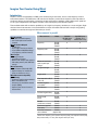
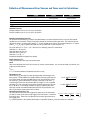
1
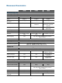
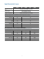
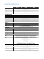
Measurement Characteristics continued
53210A
53220A
53230A
6 GHz (Option 106)
15 GHz (Option 115)
12
Pulse/burst frequency and pulse envelope detector (Option 150)
Pulse/burst measurements
N/A
N/A
Carrier frequency, carrier period, pulse repetition interval (PRI),
pulse repetition frequency (PRF), positive and negative width
Pulse/burst width
for carrier frequency
measurements10
N/A
N/A
>200 ns
Narrow: <17 µs
Wide: >13 µs
> 400 ns
Narrow: <17 μs
Wide: >13 μs
Minimum pulse/burst
width for envelope
measurements
N/A
N/A
>50 ns
> 100 ns
Acquisition
N/A
N/A
PRF, PRI range
N/A
N/A
1 Hz – 10 MHz
1 Hz - 5 MHz
Pulse detector response
time (typ)8
N/A
N/A
15 ns rise/fall
40 ns rise/fall
Pulse width accuracy
N/A
N/A
20 ns + (2*carrier period)
75 ns
Power ratio (typ)
N/A
N/A
Power range and
sensitivity (sinusoidal) typ)
N/A
N/A
Auto, Manual7
>15 dB
+13 dBm (1 Vrms) to
-13 dBm (50 mVrms)
< 3 GHz: +7 dBm (500 mVrms) to
-6 dBm (115 mVrms)
3 - 11 GHz: +9 dBm (630 mVrms) to
-8 dBm (90 mVrms)
> 11 GHz: +7 dBm (500 mVrms) to
-6 dBm (115 mVrms)
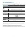
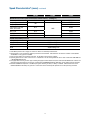
1. Maximum display resolution for frequency and period. Totalize display resolution is 15 digits, time interval based measurements
are 12 digits.
2. Continuous, gap-free measurements limits the gate time setting to 10 µs to 1000 s in 10 µs steps.
3. Refer to the gate characteristics section for more details on advanced gate capabilities.
4. Measurements on each input channel are performed simultaneously using one gate interval. The actual measurement gate interval
on each channel will be synchrounous with edges of each input signal.
5. Maximum sample rate. Actual sample rate will be limited by the input signal edge rate for signals slower than the selected sample
rate. Maximum timestamp rate offers minimal FM tolerance. If high FM tolerance is required, use lower timestamp rates.
6. Assumes two frequencies are identical, only shifted in phase.
7. Manual control of gate width and gate delay are allowed only for wide pulsed mode.
8. For pulsed signals > -7 dBm (100 mVrms) while gated on.
9. For totalize, time interval and frequency measurements, you may get measurement readings beyond the
range stated, but the accuracy of those readings is not specified.
10. Applies when burst width * Carrier Freq >80.
11. Specifications apply if measurement channels are in 5 V range, DC coupled, 50 Ω terminated and at fixed level for: time interval
single and dual channel, pulse width, duty, phase, single period and rise/fall time measurements.
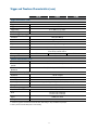
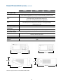
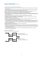
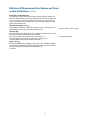
12. Option 150 microwave pulse/burst measurement descriptions:
-6 dB Detector Level
-12 dB Detector Level
(Option 106 only)
Burst carrier frequency
+ width burst (on)
Burst carrier frequency
+ width burst (on)
- 6 dB
p-p
amplitude
- 12 dB
- width burst (off)
- width burst (off)
PRF
PRI = 1/PRF
PRF
PRI = 1/PRF
7