1
OPERATORS MANUAL
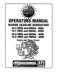
20.0KW SBEG and SBEGA • 60HZ
22.5KW SBEG and SBEGA • 60HZ
MARINE GASOLINE GENERATORS
Single and Three Phase
PUBLICATION NO.049800
THIRD EDITION
MARCH 2008
Ultra-Low Carbon Monoxide Emissions
A WARNING
Exhaust gasses contain Carbon Monoxide, an odorless and
colorless gas. Carbon Monoxide is poisonous and can cause
unconsciousness and death. Symptoms of Carbon Monoxide
exposure can include:
- Throbbing in Temples
- Dizziness
-Nausea
- Muscular Twitching
-Headache
- Vomiting
- Weakness and Sleepiness -Inability to Think Coherently
IF YOU OR ANYONE ELSE EXPERIENCE ANY OF THESE SYMPTOMS,
GET OUT INTO THE FRESH AIR IMMEDIATELY. If symptoms persist,
seek medical attention. Shut down the unit and do not restart
until it has been inspected and repaired.
A WARNING DECAL is provided by
WESTERBEKE and should be fixed to a
bulkhead near your engine or generator.
WESTERBEKE also recommends installing
CARBON MONOXIDE DETECTORS in the
living/sleeping quarters of your vessel.
They are inexpensive and easily
obtainable at your local marine store.
CALIFORNIA
PROPOSITION 65 WARNING
Marine diesel and gasoline engine
exhaust and some of its constituents
are known to the State of California
to cause cancer, birth defects,
and other reproductive harm.
SAFETY INSTRUCTIONS
•
INTRODUCTION
Read this safety manual carefully. Most accidents are
caused by failure to follow fundamental rules and precautions. Know when dangerous conditions exist and take the
necessary precautions to protect yourself, your personnel,
and your machinery.
The following safety instructions are in compliance with
the American Boat and Yacht Council (ABYC) standards.
•
•
PREVENT BURNS - EXPLOSION
PREVENT ELECTRIC SHOCK
A WARNING: explOSions from fuel vapors can cause
A WARNING: Do not touch AC electrical connections
while engine is running. Lethal voltage is present at
these connections!
•
•
•
•
•
•
enclosures and covers in place.
Shut off electrical power before accessing electrical
equipment.
Use insulated mats whenever working on electrical
equipment.
Make sure your clothing and skin are dry, not damp
(particularly shoes) when handling electrical equipment.
Remove wristwatch and all jewelry when working on
electrical equipment.
Electrical shock results from handling a charged
capacitor. Discharge capacitor by shorting terminals
together.
A WARNING: Do not touch hot engine parts or
•
•
•
•
•
•
•
All fuel vapors are highly explosive. Use extreme care
when handling and storing fuels. Store fuel in a
well-ventilated area away from spark-producing
equipment and out of the reach of children.
Do not fill the fuel tank(s) while the engine is running.
Shut off the fuel service valve at the engine when servicing
the fuel system. Take care in catching any fuel that might
spill. DO NOT allow any smoking, open flames, or other
sources of fire near the fuel system or engine when
servicing. Ensure proper ventilation exists when servicing
the fuel system.
Do not alter or modify the fuel system.
Be sure all fuel supplies have a positive shutoff valve.
Be certain fuel line fittings are adequately tightened and
free of leaks.
Make sure a fire extinguisher is installed nearby and is
properly maintained. Be familiar with its proper use.
Extinguishers rated ABC by the NFPA are appropriate
for all applications encountered in this environment.
ACCIDENTAL STARTING
exhaust system components. Arunning engine gets
very hot!
A WARNING: Accidental starting can cause injury
or death!
Always check the engine coolant level at the coolant
recovery tank.
A WARNING: Steam can cause injury or death!
•
injury or death!
Do not operate this machinery without electrical
PREVENT BURNS - HOT ENGINE
•
Do not operate with the air cleaner/silencer removed.
Backfire can cause severe injury or death.
Do not smoke or permit flames or sparks to occur near
the fuel system. Keep the compartment and the
engine/generator clean and free of debris to minimize the
chances of fire. Wipe up all spilled fuel and engine oil.
Be aware - Diesel fuel will bum.
In case of an engine overheat, allow the engine to cool
before touching the engine or checking the coolant.
PREVENT BURNS - FIRE
• To prevent accidental starting when servicing the
generator, remove the 8 amp fuse from the control panel.
• Disconnect the battery cables before servicing the engine/
generator. Remove the negative lead first and reconnect
it last.
• Make certain all personnel are clear of the engine before
starting.
• Make certain all covers, guards, and hatches are
fe-installed before starting the engine.
A WARNING: Fire can cause injury or death!
•
Prevent flash fires. Do not smoke or permit flames or
sparks to occur near the carburetor, fuel line, filter, fuel
pump, or other potential sources of spilled fuel or fuel
vapors. Use a suitable container to catch all fuel when
removing the fuel line, carburetor, or fuel filters.
EngInes & Generators
SAFETY INSTRUCTIONS
BATTERY EXPLOSION
A WARNING: Carbon monoxide (CO) is an invisible
A WARNING: Battery explosion can cause injury
odorless gas. Inhalation produces flu-like symptoms!
nausea or death!
ordeathl
•
•
•
•
Do not smoke or allow an open flame near the battery
being serviced. Lead acid batteries emit hydrogen, a
highly explosive gas, which can be ignited by electrical
arcing or by lit tobacco products. Shut off all electrical
equipment in the vicinity to prevent electrical arcing during servicing.
Never connect the negative (-) battery cable to the positive (+) connection terminal of the starter solenoid. Do
not test the battery condition by shorting the terminals
together. Sparks could ignite battery gases or fuel vapors.
Ventilate any compartment containing batteries to prevent
accumulation of explosive gases. To avoid sparks, do not
disturb the battery charger connections while the battery
•
•
•
is being charged.
Dizziness
Intense headache
Avoid contacting the terminals with tools, etc., to prevent
bums or sparks that could cause an explosion. Remove
wristwatch, rings, and any other jewelry before handling
the battery.
Always tum the battery charger off before disconnecting
the battery connections. Remove the negative lead first
and reconnect it last when disconnecting the battery.
Throbbing in temples
Weakness and sleepiness
AVOID MOVING PARTS
A WARNING: Rotating parts can cause injury
or death!
Do not service the engine while it is running. If a
situation arises in which it is absolutely necessary to
make operating adjustments, use extreme care to avoid
touching moving parts and hot exhaust system
components.
• Do not wear loose clothing or jewelry when servicing
equipment; tie back long hair and avoid wearing loose
jackets, shirts, sleeves, rings, necklaces or bracelets that
could be caught in moving parts.
• Make sure all attaching hardware is properly tightened.
Keep protective shields and guards in their respective
places at all times.
• Do not check fluid levels or the drive belt's tension while
the engine is operating.
•
BATTERY ACID
A WARNING: Sulfuric acid in batteries can cause
severe injury or deathl
• 'When servicing the battery or checking the electrolyte
level, wear rubber gloves, a rubber apron, and eye
protection. Batteries contain sulfuric acid which is
destructive. If it comes in contact with your skin, wash it
off at once with water. Acid may splash on the skin or
into the eyes inadvertently when removing electrolyte
caps.
A WARNING: Carbon monoxide (CO) is a deadly gasl
•
•
•
Do not use copper tubing in diesel exhaust systems. Diesel
fumes can rapidly destroy copper tubing in exhaust
systems. Exhaust sulfur causes rapid deterioration of
copper tubing resulting in exhaust/water leakage.
Do not install exhaust outlet where exhaust can be drawn
through portholes, vents, or air conditioners.
Although diesel engine exhaust gases are not as toxic as
exhaust fumes from gasoline engines, carbon monoxide
gas is present in diesel exhaust fumes. Some of the
symptoms or signs of carbon monoxide inhalation or
poisoning are:
Vomiting
Muscular twitching
HAZARDOUS NOISE
Ensure that the exhaust system is adequate to expel gases
discharged from the engine. Check the exhaust system
regularly for leaks and make sure the exhaust manifolds
are securely attached and no warping exists. Pay close
attention to the manifold, water injection elbow, and
exhaust pipe nipple.
Be sure the unit and its surroundings are well ventilated.
In addition to routine inspection of the exhaust system,
install a carbon monoxide detector. Consult your boat
builder or dealer for installation of approved detectors.
A WARNING: High noise levels can cause hearing
lossl
•
•
•
Never operate an engine without its muffler installed.
Do not run an engine with the air intake (silencer)
removed.
Do not run engines for long periods with their enclosures
open.
A WARNING: 00 not work on machinery when you are
mentally 01 physically incapacitated by fatiguel
Engines & Generators
ii
SAFETY INSTRUCTIONS
ABYC, NFPA AND USCG PUBLICATIONS FOR
INSTALLING DIESEL ENGINES
OPERATORS MANUAL
Many of the preceding safety tips and warnings are repeated
in your Operators Manual along with other cautions and
notes to highlight critical information. Read your manual
carefully, maintain your equipment, and follow all safety
procedures.
Read the following ABYC, NFPA and USCG publications
for safety codes and standards. Follow their recommendations when installing your engine.
ABYC (American Boat and Yacht Council)
"Safety Standards for Small Craft"
Order from:
ABYC
3069 Solomon's Island Rd.
Edgewater, MD 21037
NFPA (National Fire Protection Association)
"Fire Protection Standard for Motor Craft"
Order from:
NFPA
11 Tracy Drive
Avon Industrial Park
Avon, MA 02322
USCG (United States Coast Guard)
"USCG 33CFR183"
Order from:
U.S. Government Printing Office
Washington, D.C. 20404
GASOLINE ENGINE AND GENERATOR INSTALLATIONS
Preparations to install a gasoline engine or generator should
begin with a thorough examination of the American Boat and
Yacht Council's (ABYC) standards. These standards are from
a combination of sources including the USCG and the NFPA.
Sections of the ABYC standards of particular interest are:
H-2 Ventilation
H-24 Gasoline Fuel Systems
P-l Exhaust Systems
P-4 Inboard Engines
E-9 DC Electrical Systems
All installations must comply with the Federal Code of
Regulations (FCR).
Engines & Generators
iii
CARBON MONOXIDE "CO"/SAFE-CO GENERATORS
IMPORTANT INFORMATION
In a closed space, such as the engine compartment, the boat,
or underneath a stern swim platform, concentrations will
potentially rise to the undiluted level emanating from the
exhaust system due to a lack of fresh air to dilute the exhaust
gas. Therefore, one should never rely on dilution of the
exhaust to provide a margin of safety.
Westerbeke Safe-CO generators achieve an approximate 99%
reduction of typical CO by precise control control of the
engine's air/fuel ration coupled with after treatment in a
special catalyst. CO emissions are not the same for every
model because each engine is different. Also, certain fuel
system components are commonized across several engine
models being adequate for some and extra-adequate for
others, thus producing different CO levels for different
models.
The fuel system which accomplishes the required precise
airlfuel ratio control is comprised of many different
components: purchased sub-assemblies, machined castings,
sensors, electronics and others. Because of the extreme level
of CO reduction, any variability in the functioning of any
these components can and will cause variability of the CO
output.
CO concentration also varies with load. Usually, but not
always, the worst case CO concentration occurs at maximum
load.
DESCRIPTION
Carbon monoxide "CO" is a component of engine exhaust. It
is a colorless, tasteless, odorless, lighter than air poisonous
gas that can kill you without any warning. CO poisoning is
one of the major safety risks associated with boating. It is a
threat that must not be underestimated.
Several standards for CO have been published, expressed in
parts per million "ppm" and hours of exposure:
Regulator
EPA
ACGm
EPA
NIOSH
OSHA
ACGm
NIOSH
NIOSH
(IDLH)
CO ppm
Exposure Hours
9
25
35
35
50
125
200
1200
8
8
1
8
8
0.5
0.0
0.0
1200 ppm is the so-called IDLH concentration IMMEDIATELY DANGEROUS TO LIFE AND HEALTH.
A city in California characterizes the effect of CO
concentration this way:
Parts per Million
25
100
200
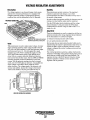
INSPECTION
Responses
The catalyst is critical to optimizing CO levels. Any water
intrusion into the exhaust system will likely quickly
compromise the proper operation of the catalyst.
Westerbeke's exhaust system installation instructions dated
on or after February 2004 must be adhered to.
NOTE: Water intrusion is not a product defect and is not
covered under warranty, neither Westerbeke's normal
product warranty nor the emissions specific warranty
mandated by various regulating authorities such as EPA
andCARB.
Maintenance of any components affecting the flow of air or
the flow of fuel to the engine is critically important, such as
fuel filters and air filters (if any).
Inspection of the catalyst at the prescribed intervals is
critically important. The exhaust elbow is removed by
loosening the metal clamp to provide a view of the output
surface of the catalyst. Any visual irregUlarity of the nonnal
flush, honeycomb appearance is most likely a result of water
intrusion. The cause of the irregularity must be identified and
addressed. If there is irregularity, the catalyst and gasket must
be replaced. Upon careful reassembly of the catalyst, exhaust
elbow gasket, and exhaust elbow, check for the presence of
CO while the engine is running. This must be performed with
a CO analyzer.
Permissible exposure level, no
apparent toxic symptoms.
No poisoning for long period.
Allowable for several hours.
Should not be exposed above
this level for any period of
time. A possible mild frontal
headache in two to three hours.
Even though Westerbeke Safe-CO generators are designed to
reduce nonnallevels of CO in the engine exhaust by
approximately 99%, an exhaust leak of untreated exhaust
would be extremely dangerous. For this reason it is
extremely important to install a CO detector near the
generator and to be sure it is always turned on and
functioning properly. If this detector sounds, do not tum it
off, assuming it is a false signal. You can not taste, smell, or
otherwise detect CO. Leave the detector on, tum off all
engines and generators, evacuate the boat leaving ports and
hatches open, and seek professional help.
As soon as CO leaves the exhaust outlet, the level is subject
to dilution in the open air. The closer a person is to the
exhaust outlet, the higher the concentration of CO.
Engines & Generators
iv
CARBON MONOXIDE "CO"/SAFE-CO GENERATORS
IMPORTANT INFORMATION
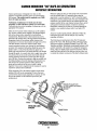
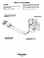
Whenever taking the time to verify proper CO concentration
from the exhaust with a CO analyzer, always take the
opportunity to use the analyzer to "sniff' around the engine
looking for CO from exhaust leaks. Pay close attention to the
connection of the cylinder head to the exhaust manifold, the
exhaust manifold to the water injected exhaust elbow, and all
subsequent downstream exhaust components and hoses.
Remember, exhaust gas that has not yet passed through the
catalyst is raw, untreated exhaust and is very high in CO
content.
Catalyst perfonnance will degrade over time. As the
generator accumulates operating hours, CO concentrations
will increase. The catalyst must be replaced every 2,000
hours of engine operation.
Verification of satisfactory CO levels must be done
seasonally or each 1,000 hours (which ever occurs first).
Verification involves actual sampling of exhaust gas with an
appropriate CO analyzer.
There are two locations where exhaust gas can be sampled.
Dry, but hot, exhaust can be sampled at the plugged tapped
hole in the exhaust elbow intended for back pressure
measurements. Measurements at this location may not be
practical in all instances due to the high exhaust temperature,
temperature limits of the analyzer, safety concerns over
temperatures involved or the possibility of high levels of CO.
The other location is the boat's exhaust outlet, which
contains entrained cooling water (except dry stack exhaust
systems). Only analyzers with probes should be used at this
location and it is critical that the probe not ingest water.
Probe-type analyzers have an air pump drawing a gas sample
through the probe. As a result, they tend to ingest water when
it is present. Be sure to aim the probe downwards with the
opening pointed in the direction of the water flow and just
out of the flow. Position the analyzer as high as possible with
the tubing leading to the probe running continuously downhill. Observe the usually trdIlslucent tubing between the
probe and the analyzer and be sure no water is being
ingested. If any water is ingested into the analyzer, it must be
repaired or replaced and recalibrated.
Analyzers usually require periodic calibration. Follow the
instructions that come with the analyzer very carefully
regarding calibration.
The following are manufacturers that offer CO analyzers:
Extech, TIP, Testo, TSI, Bacharach, Fluke, Monoxor, Fyrite,
Zellwgwer Analytics, Industrial Scientific Corp, GFG, TPI,
Teledyne and others. Westerbeke recommends analyzers with
a probe connected to the analyzer by a length of transparent
tubing. They are slightly more expensive than those with the
sensor built into one end of the analyzer, but they allow you
to sample the exhaust coming out of the boat's exhaust outlet.
When measuring CO at the exhaust outlet be aware of the
ambient CO level by also measuring CO away from and
upwind of the exhaust outlet, especially in marinas. the CO
level at the exhaust will be influenced upwards by the
ambient level.
EXHAUST MANIFOLD
Engines & Generators
v
EMISSIONS
You should carefully review operator (Owner) Installation
and other manuals and information you receive with your
genset. If you are unsure that the installation, use,
maintenance or service of your genset is authorized, you
should seek assistance from an approved WESTERBEKE
dealer.
California genset users may use the table below as an aid in
locating information related to the California Air Resources
Board requirements for emissions control.
This genset meets the requirements of California's Exhaust
Emissions Standards as stated on the nameplate.
California users of this genset should be aware that
unauthorized modifications or replacement of fuel, exhaust,
air intake, or speed control system components that affect
engine emissions are prohibited. Unauthorized modification,
removal or replacement of the engine label is prohibited.
Federal Emissions Compliance Period: The Federal
Emissions Compliance Period referred to on the nameplate
indicates the number of operating hours for which the engine
has been shown to meet Federal Emissions requirements.
Catagory C= 250 hrs, B=500 hrs,m A =1000.hrs.
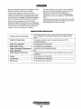
EMISSIONS CONTROL INFORMATION TABLE
Emissions Warranty Infonnation
The California emissions control warranty statement is located in the same
packet, if information as this manual when the genset is shipped from the
factory.
Engine Fuel Reqnirements
The engine is certified to operate on unleaded ga'>oline. See FUEL
RECOMMENDATIONS.
Engine Valve Adjustment
See MAINTENANCE SCHEDULE.
Engine Ignition Timing
See MAINTENANCE SCHEDULE.
Engine Lubricating on Reqnirements
See ENGINE OIL RECOMMENDATIONS.
Engine Adjustments
Engine Emission Contol System
ECU.
The engine emission control system consists of engine design and precision
manufacture.
Catalyst
See MAINTENANCE SCHEDULE.
Oxygen Sensor
See MAINTENANCE SCHEDULE.
Back Pressure
See MAINTENANCE SCHEDULE.
Engines & Generators
vi
INSTALLATION
When installing WESTERBEKE engines and generators it is important that strict
attention be paid to the following information:
CODES AND REGULATIONS
Strict federal regulations, ABYC guidelines, and safety codes must be complied with
when installing engines and generators in a marine environment.
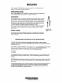
SIPHON-BREAK
For installations where the exhaust manifold/water injected exhaust elbow is close to
or will be below the vessel's waterline, provisions must be made to install a siphonbreak in the raw water supply hose to the exhaust elbow. This hose must be looped a
minimum of 20" above the vessel's waterline. Failure to use a siphon-break when
the exhaust manifold injection port is at or below the load waterline will result in
raw water damage to the engine and possible flooding of the boat.
If you have any doubt about the position of the water-injected exhaust elbow relative
to the vessel's waterline under the vessel's various operating conditions, install a
siphon-break.
AVAILABLE FROM
YOUR WESTERBEKE
DEALER
EXHAUST SYSTEM
The exhaust hose must be certified for marine use. The system must be designed to
prevent water from entering the exhaust under any sea conditions and at any angle
of the vessels hull.
EMISSION-RELATED INSTALLATION INSTRUCTIONS
"Failing to follow these instructions when installing a certified engine in a piece of non road
equipment violates federal law (40 CFR 1068.105(b), subject to fines or other penalties as described
in the Clean Air Act.".
If your product is equipped with OBD (on board diagnostics) go to www.WESTERBEKE.COM and follow
the free interface software download instructions specific to your engine to obtain and install the
appropriate diagnostic software. The following is a list ofOBD compliant products:
20.0 SBEGA
22.5 SBEGA
To sample exhaust emissions on installed OBD compliant generators, gain access to the exhaust stream by
removing the test port plug on the exhaust elbow. Be sure to reinstall the plug securely when testing is
complete.
The Westerbeke generator that you purchased is certified for constant-speed operation only. The u~e
of any Westerbeke product in any manner inconsistent with its intended use could be a viol,ation of
Federal Law.
"If you install the engine in a way that makes the engine's emission control information label hard to
read during normal engine maintenance, you must place a duplicate label on the equipment, as
described in 40 CFR 1068.105". Contact the factory for an additional engine emission control
information label if needed to comply with this rule.
Engines & Generators
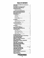
TABLE OF CONTENTS
20KW SBEG/22.5KW SBEG Parts Identification ..........2
Introduction ....................................................................3,4
Fuel, Engine Oil and Engine Coolant.. ..........................5
Preparations for Initial Start-Up ...................................6
Operating Instructlons.....................................................7
Generator Control Panel. .............................................. 7
Remote Control Start/Stop Panel ................................. 7
Break-In Procedure/Dally Operation ............................. 8
Safety Shutdown Sensors/Switches ..............................9
Maintenance Sehedule ............................................. lO,11
Cooling System ............................................................... 12
Changing Coolant ....................................................... 12
Thermostat .................................................................. 13
Zinc Anode ................................................................. 13
Heat Exchanger .......................................................... 13
Raw Water Intake Strainer ......................................... 14
Raw Water Pump ........................................................ 14
Fuel System ..................................................................... 15
GasolinelWater Separator and Filter ......................... .15
Engine Fuel Filter ....................................................... 15
Electronic Fuel Injection (EFI) .................................. 16
Engine Lubrication 011 ................................................... 17
Changing the Engine OiL ......................................... 17
Replacing the Oil Filter .............................................. 17
011 Pressure ..................................................................... 18
Testing Oil pressure .................................................... 18
Remote Oil filter (Optional) .......................................... 19
Timing Belt Inspection/lnstallation .......................20,21
Engine Adjustments .......................................................22
Spark Plugs ................................................................. 22
Drive Belt Adjustment ............................................... 22
Engine Compression Test ...........................................23
Valy~ Cl~~ce Adjustment ...................................... 24
IgnItIOn tlmlng ............................................................24
Torquing the Cylinder Head Bolts ............................. 24
Generator Information ...................................................25
The SBEG Generator (Single and Three Phase) ........ 26
Internal Wiring Schematics
(Single and Three Phase) ..............................................27
Generator AC Voltage Connections .................28, 29 30
SBEG Troubleshootlng ....................................................31
Generator Voltage Regulator Adjustments
(Three Phase) ..................................................................32
Shore Power Transfer Switch .......................................33
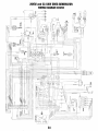
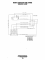
20KW SBEG and 22.5KW SBEG
Generator Wiring Diagram #49232 ..............................34
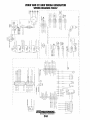
Remote Control Panel
Wiring Diagram #49209 ................................................ .35
Engine Troubleshootlng ..................................36,37,38,39
Lay-Up and Recommissioning .................................40,41
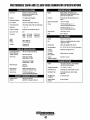
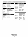
20KW SBEG and 22.5KW SBEG
Generator Specifications .........................................42,43
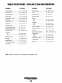
Torque Specifications ....................................................44
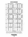
Standard and Metric Conversion Data .......................45
Metric Conversions ........................................................46
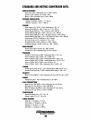
Suggested Spare Parts ................................................. .47
...,y'
WESTERBEKE
Engines & Generators
1
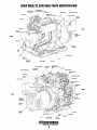
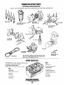
20KW SBEG/22.5KW SBEG PARTS IDENTIFICATION
SCHRAIIER VAlVE
FUEL PRESSURE REGULATOR
SENSOR (liB)
AIR HEATER
CIRCUIT
BREAKER
REAR
OXYGEN
SENSOR tIVBli7~?~~;+_-\L
~'" _T--_
fRONT
EXHAUST
TEMPERATURE
SWITCH
BELT GUARD
EXHAUST
CONNECTION
ISOLATOR MOUNT
HEAT
EXCHANGER
RAll
RAW WATER
DISCHARGE
lEFT SIDE
AIR BLEED PETCOCK
OXYGEN SENSOR (NB)
OIL SUMP
COIIJBALLAST
REGISTER
\
SYPHON BREAK
CONNECTION
HOUR METER
COOLANT FILL
(MANIFOLD PRESSURE
CAP)
Oil Fill CAP
I
THERMOSTAT ASSEMBLY
fAULT lEO
LIGHTS
CONTROL PANEL
FRONT
REAR
RAW WATER
PUMP
GEIIERATOR
OIL FILTER
8ACKENO
RAIL
RIGHT SIDE
IN-LINE
FUEL FILTER
Engines & Generators
2
INTRODUCTION
WESTERBEKE CANNOT BE RESPONSIBLE FOR THE
CONTENT OF SUCH SOFTWARE, MAKES NO
WARRANTIES OR REPRESENTATIONS WITH
RESPECT THERETO, INCLUDING ACCURACY,
TIMEUNESS OR COMPLETENESS THEREOF AND
WIUIN NO EVENT BE UABLE FOR ANY TYPE OF
DAMAGE OR INJURY INCURRED IN CONNECTION
WITH OR ARISING OUT OF THE FURNISHING OR
USE OF SUCH SOFTWARE.
WESTERBEKE customers should also kcep in mind the
time span between printings of WESTERBEKE product
software and the unavoidable existence of earlier
WESTERBEKE manuals. In summation, product software
provided with WESTERBEKE products, whether from
WESTERBEKE or other suppliers, must not and cannot
be relied upon exclusively as the definitive authority on
the respective product. It not only makes good sense
but is imperative that appropriate representatives of
WESTERBEKE or the supplier in question be consulted
to determine the accuracy and currentness of the
product software being consulted by the customer.
This WESTERBEKE Generator is a product of
WESTERBEKE's long years of experience and advanced
technology. We take great pride in the superior durability and
dependable performance of our engines and generators.
Thank you for selecting WESTERBEKE.
In order to get the full use and benefit from your generator, it
is important that you operate and maintain it correctly. This
manual is designed to help you do this. Please read this
manual carefully and observe all the safety precautions
throughout. Should your generator require servicing, contact
your nearest WESTERBEKE dealer for assistance.
This is your operators manual. Along with this manual there
is an Installation manual and a unit parts print. A Service
manual is available and can be ordered from your local
WESTERBEKElUl\lVERSAL dealer.
WARRANTY PROCEDURES
Your WESTERBEKE Warranty is included in a separate
folder. If you have not received a customer identification card
registering your warranty 60 days after submitting the
warranty registry form, please contact the factory in
writing with model information, including the unit's serial
number and commission date.
SERIAL NUMBER LOCATION
The engine and generator serial numbers and model numbers
are located on a decal on the generator housing. Take the
time to enter the information on the blank decal provided
below as this will provide a quick reference when seeking
technical information andlor ordering repair parts.
,..".".,WESTERBEKE
I
E.ngines & Generators
Customer Identification
WESTERBEKE OWNER
MAIN STREET
HOMETOWN, USA
Model
Ser.#
Expires
60 HZ.
SPECIFICATION 50 HZ.
MODEL ___ ___ _
~
RPM._. _______ _
KW ___________ _
KVA __________ _
VOLTS ________ _
AMPS ________ _
CUSTOMER IDENTIFICATION CARD (TYPICAL)
The WESTERBEKE serial number is an alphanumeric
number that can assist in determining the date of
manufacture of your WESTERBEKE engine/generator.
The first character indicates the decade (A=1960's,
B=1970', C=1980's, D=1990's, E=2000's), the second
character represents the year in the decade, and the fourth
and fifth numbers represent the month of manufacturer.
ENG. HP ______ _
ENG. SER. NO.
GEN. SER. NO.
PF/PHASE ___ _
WIRES ________ _
PRODUCT SOFTWARE
I
RATING. ______ _
Product software, (tech data, parts lists, manuals, brochures
and catalogs), provided from sources other than
WESTERBEKE are not within WESTERBEKE'S
CONTROL.
INSUL CLASS __
TEMP. RISE ___ _
BAlTERY _____ _
e.I.D. _________ _
Fin in the information for your own reference.
Engines & Generators
3
INTRODUCTION
The engine/generator model number and serial number are
located on a plate mounted on the engine's valve cover.
PROTECTING YOUR INVESTMENT
Care at the factory during assembly and thorough testing
have resulted in a WESTERBEKE generator capable of
many thousands of hours of dependable service. However the
manufacturer cannot control how or where the generator is
installed in the vessel or the manner in which the unit is
operated and serviced in the field. this is up to the
buyer/owner operator.
NOTE: Six important steps to ensure long generator lifo:
• Proper engine and generator installation.
• An efficient weU-designed exhaust system that includes an
anti-siphon break to prevent water from entering the
engine.
UNDERSTANDING THE DIESEL ENGINE
The gasoline engine driving an AC generator is in many ways
similar to a gasoline automobile engine. The cylinders are
vertic1e in-line, and the engine's cylinder head has an overhead camshaft which is chain-driven. The engine utilizes a
solid-state distributor which is horizontally mounted and
camshaft-driven. The engine incorporates a pressure type
lubrication system, and a fresh water-cooled engine block
which is thennostatically controlled. To a large degree, the
generator's engine requires the same preventative maintenance
that is required of a gasoline automobile engine. the most
important factors to the generator's longevity are proper
ventilation, maintenance of the fuel system, ignition system,
cooling system and the generator back-end.
•
•
•
•
Changing the engine oil and oilfilters every 100 operating
hours.
Proper maintenance ofall engine and generator
components according to the maintenance schedule in
this manual.
Use clean,filtered unleadedfuel.
Winterize your engine according to the lAY-UP AND
RECOMMISSIONING section in this manual.
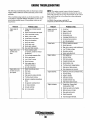
ORDERING PARTS
SPARES AND ACCESSORIES
Whenever replacement parts are needed, always provide the
generator and engine model and serial numbers. In addition,
include a complete part description and part number for each
part needed. Also insist upon WESTERBEKE packaged parts
because will fit or generic parts are frequently not made to the
same specifications as original equipment.
Certain spares will be needed to support and maintain your
WESTERBEKE generator or engine when cruising (see
SUGGESTED SPARE PARTS). Often even simple items such
as proper fuel and oil filters can be difficult to obtain along
the way. WESTERBEKE will provide you with a suggested
spares and accessories brochure to assist you in preparing an
on-board inventory of the proper WESTERBEKE parts.
NOTES, CAUTIONS AND WARNINGS
As this manual takes you through the operating procedures,
maintenance schedules, and troubleshooting of your
generator" critical infonnation will be highlighted by NOTES,
CAUTIONS, and WARNINGS. An explanation follows:
NOTE: An operating procedure essential to note.
A CAUTION: Procedures, which if not strictly
observed, can result in the damage or destruction of your
engine.
A WARNING: Procedures, which if not properly
followed, can result in personal injury or loss of life.
Engines & Generators
4
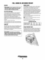
FUEL, ENGINE OIL AND ENGINE COOLANT
ENGINE COOLANT
GASOLINE
WESTERBEKE recommends a mixture of 50% antifreeze
and 50% distilled water. Distilled water is free from the
chemicals that can corrode internal engine surfaces.
The antifreeze performs double duty. It allows the engine
to run at proper temperatures by transferring heat away from
the engine to the coolant. It also lubricates and protects the
cooling circuit from rust and corrosion. Use a good quality
antifreeze that contains supplemental cooling additives
(SeAs') that keep the antifreeze chemically balanced, crucial
to long term protection.
The water and antifreeze should be premixed before being
poured into the cooling circuit.
A CAUTION: Only use unleaded fuel with an octane
rating of 89 or higher. Leaded fuel will cause serious
harm to your engine and violate your warranty.
Care Of The Fuel Supply
Use only clean fuel! The clearance of the components in
your fuel injection pump is very critical; invisible dirt
particles which might pass through the filter can damage
these finely finished parts. It is important to buy clean fuel,
and keep it clean. The best fuel can be rendered
unsatisfactory by careless handling or improper storage
facilities. To assure that the fuel going into the tank for your
engine's daily use is clean and pure, the following practice is
advisable:
Purchase a well-known brand of fuel.
Install and regularly service a good, Coast Guard approved
metal bowl type filter/water separator between the fuel tank
and the engine.
NOTE: Use the new environmentally-friendly, long lasting,
antifreeze that is now available.
A proper 50/50 mixture as recommended will protect the
engine coolant to temperatures of -4()0F.
ANTIfREEZE PROTECTION
Antifreeze Concentration
Freezing Temperature
ENGINE OIL
Use a heavy duty engine oil with an API classification of SJ.
Change the engine oil and filter after an initial 50 hours of
break-in operation, and every 100 hours of operation
thereafter. An oil viscosity of SAE 15W-40 is recommended
for this engine in all conditions.
23%
14°F
(-10°C)
30%
8°F
(-13"C)
35%
-4°F
(-20"C)
50%
-40°F
(-40°G)
COOLANT RECOVERY TANK
A coolant recovery tank kit is supplied with each generator.
The purpose of this recovery tank is to allow for engine
coolant expansion and contraction during engine operation.
Some loss of coolant may occur as a result of evaporation
and the effects of exhaust manifold working temperature.
A CAUTION: Do not allow two Dr more brands of
engine oil to mix. Each brand contains its own additives;
additives of different brands could react in the mixture
to produce properties harmful to your engine.
Engines & Generators
5
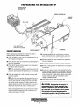
PREPARATIONS FOR INITIAL START-UP
PLASTIC COOLANT
RECOVERY TANK
MANIFOLD PRESSURE CAP
AIR BLEElJ
PETCOCK
THIS LINE RETURNS
COOLANT TO THE ENGINE
PRESTART INSPECTION
OIL DIPSTICK
EXHAUST MANIFOLD
Before starting your generator for the first time or after a
prolonged layoff, check the following items:
• Visually examine the unit. Look for loose or missing
parts, disconnected wires, unattached hoses, and check
threaded connections. Search for any gasoline leaks.
• Check the engine oil level: add oil to maintain the level at
the full mark on the dipstick
• Check load leads for correct connections as specified in
the wiring diagrams.
• Check the fuel supply and examine the fuel filter/separator
bowls for contaminants.
• Examine the air inlet and outlet for air flow obstructions.
• Check the DC electrical system. Inspect wire connections
and battery cable connections.
• Be sure no other generator or utility power is connected to
the load lines.
NOTE: The starting battery must be totally dedicated to the
generator and maintained by the generator's DC charging
alternator and no other source.
• Be sure that in power systems with a neutral line that the
neutral is properly grounded (or ungrounded) as the system
requires, and that generator neutral is properly connected
to the load neutral. In single phase systems an incomplete
or open neutral can supply the wrong line-to-neutral
voltage on unbalanced loads.
• Check the coolant level in both the plastic recovery tank
and at the manifold.
NOTE: After the initial running of the generator, the air in
the engine's cooling system will be purged to the coolant
recovery tank. Open the air bleed petcock to ensure that
the cooling system is purged of air. After shutdown and
after the engine has cooled, the coolant from the recovery
tank will be drawn into the engine's cooling system to
replace the purged air.
Before subsequent operation of the generator, the engine's
manifold should be topped off and the coolant recovery
tank's level brought to 114 full.
• Make certain the raw water tbm-hull is open.
A CAUTION:
When starling the generator, it is
recommended that all AC loads. especially large
motors. be switched OFF until the engine has come
up to speed and. in cold climates, starts to warm up.
This precaution will prevent damage caused by
unanticipated operation of the AC machinery and will
prevent a cold engine from stalling.
Engines & Generators
6
OPERATING INSTRUCTIONS
CAUTION: When servicing or replacing DC
components, tum offtbe 20 amp DC circuit breaker.
fW'/WES1ERBEKE
0
'-r--r--r---r-'~
DC CIRCUIT
BREAKER
ON/OFF
START
EMERGENCY STOP
AND FIREBOY
CONNECTIONS
T
STOP
o
STOP SWITCH
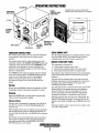
GENERATOR CONTROL PANEL
CHECK ENGINE LIGHT
The start/stop rocker switch is the only functional component
on the generator control panel used to start and stop the
generator.
The start/stop rocker switch is a three position switch with
momentary contacts in the (START) and (STOP) position and
a stationary contact function in the center (NORMAL). This
position allows the generator to run once started and also
enables the remote start/stop panel(s) to control the start/stop
functions of the generator.
The (START) position starts the generator and once released
reverts to the center position. The (STOP) position stops the
engine in normal operation as well as in an emergency
situation. This position opens the K2 run relay which
de-energizes the engine's run circuit and shuts down the
engine.
The check engine light indicates a potential emission's control
issue. Immediate action by the operator should be taken to
troubleshoot and correct the emission's related issue.
REMOTE START/STOP PANEL
The components on the panel are:
1. A three position start/stop rocker switch.
2. A green LED run indicator light on the rocker switch.
3. A four position LED fault shut down display board.
The start/stop rocker switch functions the same as the start/stop
rocker switch on the genemtor's control panel as previously
explained.
The green LED run indicator light on the rocker switch will
illuminate when the start circuit is energized. It ,vill go dim as
the engine cranks and will brighten as the engine starts
indicating the generator is running.
The LED fault shut down display board has four separate LED
lights to display to the operator the cause of the generators
automatic shut down. The four LED displays are: low oil
pressure, high engine operating temperature, high exhaust
temperature and engine over-speedlunder-speed (flashes).
Should the genemtor shut down from one of these faults, the
fault LED will remain illuminated. To reset the LED, the DC
breaker on the control box must be turned OFF and then back
ON.
This remote panel is a plub-in accessory and is availab;e with a
15' to 100' wiring harness.
Starting
Simply press the (START) switch and the generator will start.
A green light will glow indicating the generator is running.
Stopping
Depress the (STOP) side of the start switch, the green light
will go out and the generator is stopped.
Failure to Start
The start cycle will automatically terminate if the unit fails to
start after 5-6 seconds of cranking. Wait 20 seconds, then
repeat the start.
If the unit again fails to start, investigate the cause. Sometimes
after servicing the fuel system or changing the fuel filter, air
can accumulate in the fuel line or the throttle body and prevent
starting.
The Schrader valves on the throttle body and the fuel cell are
used to remove trapped air. This air is mixed with fuel and
under high pressure. Follow the BLEEDING 11IE FUEL
SYSTEM instructions in this manual.
-
Engines & Generators
7
BREAK-IN PROCEDURE/THE DAILY OPERATION
BREAK~IN PROCEDURE
After the generator has been started, check for proper
operation and then encourage a fast wann-up. Run the
generator between 20% and 60% of full-load for the first
10 hours.
NOTE: Some unstable running may occur in a cold engine.
This condition should lessen as normal operating temperature
is reached and loads are applied.
A CAUTION: Do not operate the generator for long
periods of time without a load being placed on the
generator. '
A CAUTION: 00 not attempt to break-in your
generator by running without a load.
GENERATOR ADJUSTMENTS
After the first 10 hours of the generators operation, the load
can be increased to the full-load rated output, then
periodically vary the load.
Avoid overload at all times. An overload is signaled by
smoky exhaust with reduced output voltage and frequency.
Monitor the current being drawn from the generator and keep
it within the generators rating. Since the generator operates at
1800 rpm to produce 60 hertz, control of the generator's
engine break-in is governed by the current drawn from the
generator.
To protect against unintentional overloading of the gen!<rator,
the generator's output leads should be routed through a
circuit breaker that is rated at the rated output of the
generator.
Once the generator has been placed in operation, there may
be governor adjustments required for engine speed (hertz)
during the engine's break-in period (first 50 hours) or after
this period.See ENGINE SPEED (HERTZ) ADJUSTMENT
under ENGINE ADJUSTMENTS).
NOTE: After the first 50 hours of generator operation, check
the maintenance schedule for the 50 hour service check.
A WARNING: VENTILATION
GaSoline vapors can explode. Before starting the engine,
operate the blower for at least four minutes and check both
'the engine compartment and bilge for gasoline vapors. Run
the blower below cruising.speed.
NOTE: Be aware of motor starting loads and the high current
drawn required for starting motors. The starting amperage
drawn can be 3 to 5 times normal running amperage. See
GENERATOR INFORMATION in this manual.
CHECK LIST
Follow this check list each day before starting your generator.
• Record the hourmeter reading in your log (engine hours
relate to the maintenance schedule).
• Visually inspect the generator for fuel, oil, or water leaks.
• Check the oil level (dipstick).
• Check the coolant level in the coolant recovery tank.
• Check your fuel supply.
• Check the starting batteries (weekly).
• Check drive belts for wear and proper tension (weekly).
• Check for abnormal noise such as knocking, vibration and
blow-back sounds.
• Check drive belts for wear and proper tension (weekly).
• Confirm exhaust smoke:
When the engine is cold - white smoke.
When the engine is wann - almost smokeless.
When the engine is overloaded - some black smoke.
Engines & Generators
8
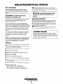
SAFETY SHUTDOWN SENSORS AND SWITCHES
SAFETY SHUTDOWN SWITCH/SENSORS
Oil Pressure Sensor
The engine is protected by four automatic shutdown circuits.
Should a shutdown occur, do not attempt to restart without
finding and correcting the cause. Refer to the heading
Engine starts, rWlS and then shuts down in the ENGINE
TROUBLESHOOTING section of this manuaL
The following is a description of these automatic shutdown
circuits:
An oil pressure sensor is located off the engines oil gallery.
Oil pressure on the sensor affects the DC voltage through the
sensor to the ECU. Should the voltage reach a preset value,
the ECU will interpret this as a low oil pressure issue and
open the K2 run relay, stopping the generator. The oil
pressure LED on the panel will illuminate.
High Exhaust Temperature Switch
An exhaust temperature switch is located on the water
injected exhaust elbow. Normally closed, this switch will
open and the ECU will interpret this as a high exhaust
temperature and open the K2 run relay, stopping the
generator. The exhaust temperature LED on the panel will
illuminate. The switch opens at 260-270F (127-132C). This
switch resets (contacts close) at approximately 225F (107C).
JiO ~
~
~q.~
:3
P
If
i'
~
Oil PRESSURE
SENSOR
Engine DC Circuit Breaker
HIGH EXHAUST
TEMPERATURE
SWITCH
The generator's engine DC circuit is protected by a rocker
type DC 20 amp breaker mounted on the control box. This
also serves as an Emergency Stop Switch. Excessive DC
current draw or DC electrical overload anywhere in the
instrument panel wiring or engine wiring will cause the
breaker to trip to the OFF position. In this event, the DC
power to the ECU will be interrupted, stopping the generator.
No panel LED will illuminate. Check and repair the source
of the problem. After repairing the fault, reset the breaker and
restart the generator.
MOUNTED ATTHE
EXHAUST ELBOW
High/Low RPM Shutdown
Water Temperature Sensor
Should the generator's RPM go above 20% of the specified
1800 rpm @ 60 HzJ1500 rpm @ 50 Hz, the ECU will shut
the engine down on an over speed fault and illuminate the
over speed LED on the control panel and remote start/stop
panel when installed
Should the generator's RPM fall below 20% of the specified
1800 rpm @ 60 HZ/I500 rpm @ 50 Hz, the ECU will shut
the engine down on an under speed fault and this will cause
the over speed LED to flash.
The OBD (On Board Diagnostic) will also show these faults.
A water temperature sensor is located at the thermostat
housing. This sensor sends a DC voltage to the ECU that it
interprets as engine antifreeze coolant temperature. Should
this voltage reach a set value, the ECU will interpret this as
high antifreeze coolant temperature and open the K2 run
relay, stopping the generator. The overheat LED on the panel
will then illuminate.
Engines & Generators
9
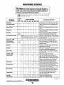
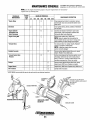
MAINTENANCE SCHEDULE
A
WARNING: Never attempt to pedorm any service while the engine is
running. Wear the proper safety equipment such as goggles and gloves, and
use the correct tools for each job. Disconnect the battery terminals when
servicing any of the engine's DC electrical equipment.
ISAFE
IMaintenance items that are very important to the proper operation of
CO "Safe
generators.
CO"
SCHEDULED
MAINTENANCE
Fuel Supply
CHECK
EACH
DAY
HOURS OF OPERATION
50
100 250
500
MAINTENANCE DESCRIPTION
750 1000 1250
Unleaded gasoline with octane rating of 89 of higher
fuel/Water Separator
0
0
Engine Oil Level
0
Oil level should indicate between MAX. and LOW on
dipstick.
Coolant Level
0
Check for water and dirt in fuel (drain/replace filter if
necessary).
Check at recovery tank; if empty, check at manifold.
Add coolant if needed.
Drive Belts
Visual Inspection of Engine
Sparks Plugs ISfbEI
Starting BaHeries
(and House Batteries)
Engine Oil
Generator
Fuel Lift Pump
Air Screen ISfbEI
Exhaust System
Engine Hoses
Raw Water Pump
Heat Exchanger
Coolant System
Fuel Filter
Inlet fuel Filter
~y
Inspect for proper tension (3/8" to 1/2" deflection)
and adjust if needed. Check belt edges for wear.
0
NOTE: Keep engine surface clean. Dirt and oil Check for fuel, oil and water leaks. Inspect wiring and
electrical connections. Keep bolts & nuts tight. Check
will inhibit the engine's ability to remain eoo/.
for loose belt tension.
0
0
0 0 0
0 Check gap, inspect for burning and corrosion.
Every 50 operating hours check electrolyte levels
0
weekly
and make sure connections are very tight. Clean off
excessive corrOSion.
0 0 0 0 Initial engine oil and filter change at 50 hours, then
DID 0
change both every 100 hours.
0 0 1010 0 DID Check that AC connections are clean and secure with
no chafing-see GENERATOR INFORMATION.
Periodically inspect for leaks, electrical connections
0
are clean and tight.
Clean at 50 hrs., then every 100 hours.
0
0
0
0 Initial check at 50 hours, then every 250 hours.
0
Inspect for leaks. Check anti-Siphon valve operation.
Check the exhaust elbow for carbon and/or corrosion
buildup on inside passages; clean and replace as
necessary. Check that all connections are tight.
0 0
0 0 [J 0
0 Hose should be hard & tight. Replace if hoses
become spongy. Check and tighten all hose clamps.
0
0 Remove the pump cover and inspect for wear.
0
Inspect impeller, cam and wear plate. Replace gasket.
Lubricate impeller when reassembling.
0 0 0 0 Clean or replace anode. Open heat exchanger end
10 0 0
cap and clean out debris. Remove every 1000 hours
for professional cleaning and pressure testing.
Drain, flush, and refill cooling system with
0
10
appropriate antifreeze mix.
0
0 0 0 0 0 Change every 250 operating hours.
0 0
0 0 0 0 Change every 250 operating hours.
(continued)
CAUTION: When servicing or replacing DC
components, tum off the 20 amp DC circuit breaker.
Engines & Generators
10
MAINTENANCE SCHEDULE
CAUTION: When servicing or replacing DC
components, tum off the 20 amp DC circuit breaker.
NOTE: Use the engine hourmeter gauge to log your engine hours or record your
engine hours by running time.
CHECK
EACH
DAY
SCHEDULED
MAINTENANCE
HOURS OF OPERATION
50
100 250
"'Starter Motor
Distri butor
0
MAINTENANCE DESCRIPTION
500 750 1000 1250
1
0
Check solenoid and motor for corrosion. Remove
and lubricate. Clean and lubricate the starter motor
pinion drive.
0
Check ignition timing. Check condition of distributor
cap and rotor.
*Engine Cylinder
Compression and
Valve Clearances
0
*Engine Timing Belt
0
0
Incorrect valve clearance will result in poor engine
performance, check compression pressure and
timing and adjust valve clearances.
Remove and replace every 1000 hours.
NOTE: Failure to replace the timing belt at the
recommended inteNal could result in timing chain
failure resulting in major damage to the engine.
0
*Exhaust Elbow
Test exhaust elbow for casting integrity. Replace if
casting is corroded or deteriorated.
NOTE: A defective exhaust elbow can cause
carbon monoxide leakage!
Catalytic Converter
0
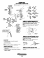
"'Exhaust System Back
Pressure
0
Perform back pressure test to ensure system is not
developing restrictions that will increase pressure
above 1.5 PSI or 41 inches of water column at full
operating amperage load. Correct as needed.
Catalyst
-
Oxygen Sensor
CO in Exhaust
0
Remove water injected exhaust elbow and visually
inspect every 2000 hours. Replace as needed.
0
0
Inspect every 1000 hours. Replace every 2000 hours.
Sample with CO analyzer.
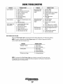
*WESTERBEKE recommends this service be performed by an authorized mechanic.
ADJUSTABLE
CLAMP
EXHAUST
, MANIFOLD
r
41"
I
MEASURING EXHAUST BACK-PRESSURE •
i
Remove water injected exhaust elbow and visually
inspect. Replace every 2000 hours.
INSTALLING A NEW
CATALYST
Engines & Generators
11
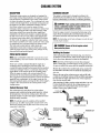
COOLING SYSTEM
DESCRIPTION
CHANGING COOLANT
Westerbeke marine engines are designed and equipped for
fresh water cooling. Heat produced in the engine by combustion and friction is transferred to fresh water coolant which
circulates throughout the engine. This circulating fresh water
coolant cools the engine block, its internal moving parts and
the engine oil. The heat is transferred externally from the
fresh water coolant to raw water by means of a heat
exchanger, similar in function to an automotive radiator. Raw
water flows through the tubes of the heat exchanger while
fresh water coolant flows around the tubes; engine heat
transferred to the fresh water coolant is conducted through
the tube walls to the raw water which is then pumped into
the exhaust system where finally it is discharged overboard.
In other words, the engine is cooled by fresh water coolant,
this coolant is cooled by raw water, and the raw water carries
the transferred heat overboard through the exhaust system.
The fresh water coolant and raw water circuits are
independent of each other. Using only fresh water coolant
within the engine allows the cooling water passages to stay
clean and free from harmful deposits.
The engine's coolant must be changed according to the
MAINTENANCE SCHEDULE. If the coolant is allowed to
become contaminated, it can lead to overheating problems.
A CAUTION: Proper cooling system maintenance is
critical; a substantial number of engine failures can be
traced back to cooling system corrosion.
Drain the engine coolant by loosening the drain plug on the
engine block and opening the manifold pressure cap. Flush
the system with fresh water, then start the refill process.
NOTE: The drain plug on the heat exchanger can also be used
to drain engine coolant.
A WARNING: Beware of the hot engine coo/ant.
Wear protective gloves.
Refilling the Coolant
FRESH WATER CIRCUIT
After replacing the engine block drain plug, close the heat
exchanger's coolant petcock. Then run the engine at idle and
slowly pour clean, premixed coolant into the manifold.
NOTE: Refer to ENGINE COOLANT section for the recommended antifreeze and water mixture to be used as the fresh
water coolant.
NOTE: Open the air-bleed petcock on the heat exchanger.
When a steady flow of coolant appears at the petcock, close
the petcock and fill the SY$tem until the manifold remains full.
Fresh water coolant is pumped through the engine by a
circulating pump, absorbing heat from the engine. The
coolant then passes through the thermostat into the manifold,
to the heat exchanger where it is cooled and returned to the
engine block via the suction side of the circulating pump.
When the engine is started cold, external coolant flow is
prevented by the closed thermostat (although some coolant
flow is bypassed around the thermostat to prevent the exhaust
manifold from overheating). As the engine warms up, the
thermostat gradually opens, allowing full flow of the engine's
coolant to flow unrestricted to the external portion of the
cooling system.
Monitor the coolant in the manifold and add as needed. Fill
the manifold to the filler neck and install the manifold pressure cap.
Remove the cap on the coolant recovery tank and fill with
coolant mix to halfway between LOW and MAX and replace
the cap. Run the engine and observe the coolant expansion
flow into the recovery tank.
After checking for leaks, stop the engine and allow it to cool.
Coolant should draw back into the cooling system as the
engine cools down. Add coolant to the recovery tank if
needed. Clean up any spilled coolant.
Coolant Recovery Tank
The coolant recovery tank allows for engine coolant
expansion and contraction during engine operation, without
the introduction of air into the cooling system. This tank
should be located at or above the engine manifold level and
should be easily accessible.
TO COOLANT
RECOVERY
NOTE: Periodically check the condition of the manifold
pressure cap, its rubber seals and the vacuum retum valve.
Ensure the passage from the filler neck to the recovery tank
connection is kept clear.
COOLANT EXPANSION
PRESSURE CAP
;/
Engines & Generators
12
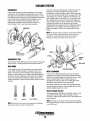
COOLING SYSTEM
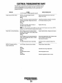
THERMOSTAT
A thennostat controls the coolant temperature as the coolant
continuously flows through the closed cooling circuit. When
the engine is first started the closed thennostat prevents coolant
from flowing (some coolant is by-passed through the thennostat
to p~vent the exhaust manifold from overheating). As the
engIne wanns up, the thennostat gradually opens. The
thennostat is accessible and can be checked, cleaned, or
replaced easily. Carry a spare thennostat and gasket.
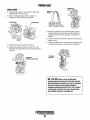
If the zinc anode needs replacement, hold the hex boss into
which the zinc anode is threaded with a wrench while
loosening the anode with another wrench. This prevents the
hex boss from possibly tearing off the exchanger shell. After
removing the zinc, note the condition of it. If the zinc is in
poor condition, there are probably a lot of zinc flakes within
the exchanger. Remove the end of the heat exchanger and
clean the inside of all zinc debris. Always have a spare heat
exchanger end gasket in case the present one becomes
damaged when removing the end cover. Replace the sealing
gasket (refer to your engine model's heat exchanger end
gasket part number), O-ring, cover, and install a new zinc
anode.
NOTE: The threads of the zinc anodes are pipe threads and do
not require sealant. sealant shmdd not be used as it may
insulate the zinc from the metal of the heat exchanger
housing preventing electrolysis action on the zinc.
GASKET
(APPLY SEALANT
TO BOTH SIDES)
THERMOSTAT TEST
If you suspect a faulty thennostat, place it in a pan of water and
bring to a boil. A working thennostat should open about 112"
ZINC ANODE
ZINC ANODE
~ zi~c ~o~e (or pencil) is located in the raw water cooling
CIrcUlt wIthm the heat exchanger. The purpose of the zinc
~ode is to sacrifice itself to electrolysis action taking place
1ll the raw water cooling circuit, thereby reducing the effects of
electrolysis on other components of the system. The condition
of the zinc anode should be checked monthly and the anode
cleaned or replaced as required. Spare anodes should be carried
on board.
HEAT EXCHANGER
"
Cool raw water flows through the inner tubes of the heat
exchanger. As the engine coolant passes around these tubes,
the heat of the internal engine is conducted to the raw water
which is then pumped into the exhaust system and
discharged. The engine coolant (now cooled) flows back
through the engine and the circuit repeats itself.
The engine coolant and raw water are independent of each
other; this keeps the engine's water passages clean from the
harmful deposits found in raw water.
Heat Exchanger Service
NEW
REPLACE
After approximately 1000 hours of operation, remove, clean
and pressure test the engine's heat exchanger. (A local
automotive radiator shop should be able to clean and test the
heat exchanger.)
CLEAN &REUSE
NOTE: Operating in silty and/or tropical waters may require
that a heat exchanger cleaning be perfonned more often than
every 1000 hours.
NOTE: Electrolysis is the result of each particular installation
and vessel location, not that of the generator.
Engines & Generators
13
COOLING SYSTEM
RAW WATER INTAKE STRAINER
RAW WATER PUMP
NOTE: Always install the strainer at or below the waterline so
The raw water pump is a self-priming, rotary pump with a
non-ferrous housing and a Neoprene impeller. The impeller
has flexible blades which wipe against a curved cam plate
within the impeller housing, producing the pumping action.
On no account should this pump be run dry. There should
always be a spare impeller and impeller cover gasket aboard
(an impeller kit). Raw water pump impeller failures occur
when lubricant (raw water) is not present during engine
operation. Such failures are not warrantable, and operators
are cautioned to make sure raw water flow is present at
start-up. The raw water pump should be inspected
periodically for broken or tom impeller blades. See
MAINTENANCE SCHEDULE.
the strainer will always be self-priming.
A clean raw water intake strainer is a vital component of the
engine's cooling system. Include a visual inspection of this
strainer when making your periodic engine check. The water
in the glass should be clear.
Perform the following maintenance after every 100 hours of
operation:
1. Close the raw water seacock.
2. Remove and clean the strainer filter.
3. Clean the glass.
4. Replace the sealing washer if necessary.
5. Reassemble and install the strainer.
6. Open the seacock.
7. Run the engine and check for leaks.
Changing the Raw Water Pump Impeller
Close the raw water intake valve. Remove the pump cover
and, with the aid of two small screwdrivers, carefully pry the
impeller out of the pump. Install the new impeller and gasket.
Move the blades to conform to the curved cam plate and
push the impeller into the pumps housing. When assembling,
apply a thin coating of lubricant to the impeller and gasket.
Open the raw water intake valve.
NOTE: Also follow the above procedure after having run hard
aground.
If the engine temperature gauge ever shows a higher than
normal reading, the cause may be that silt, leaves or grass
may have been caught up in the strainer, slowing the flow of
raw water through the cooling system.
STRAINER
A CAUTION: If any of the vanes have broken off the
RAW WATER INTAKE STRAINER
OWNER INSTALLED (TYPICAL)
impeller, they must be found to prevent blockage in the
cooling circuit. They often can be found in the heat
exchanger.
Engines & Generators
14
FUEL SYSTEM
GASOLINE
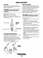
Changing Filter Element
Use unleaded 89 octane or higher gasoline. When fueling,
follow U.S. Coast Guard regulations, close off all hatches and
companionways to prevent fumes from entering the boat, and
ventilate after fueling.
1. Shut off the fuel supply.
2. Ensure there is no pressure in the fuel system by bleeding
off any existing pressure using a Schrader valve on the
throttle body and the fuel celL Use a pressure testing kit as
shown below.
3. Unscrew the fuel bowl from the housing and allow the
bowl to come away from the housing.
4. Remove and replace the filter element and clean the bowl.
S. Inspect both a-rings. Replace if necessary.
6. Press on a new filter and replace the filter bowl.
7. Open the fuel supply. Inspect for leaks.
NOTE: The generator compartment should have a gasoline fume
detector/alarm plVperly installed and working.
GASOLlNEJWATER SEPARATOR AND FILTER
A primary fuel filter of the water separating type must be
installed between the fuel tank and the engine to remove
water and other contaminant's from the fuel before they can
be carried to the fuel system on the engine.
These gasoline filters must have metal bowls (not "seethrough") to meet U.S. Coast Guard requirements. The metal
bowls have drain valves to use when checking for water and
impurities.
INLET FUEL FILTER
1. Shut off the fuel supply to the generator. Disconnect the
fuel supply line to the inlet filter and unscrew the filter
from the pump inlet. Take care to catch any fuel that may
be present.
2. Thread on the replacement inlet filter and connect the fuel
supply line. Use care when connecting and tightening the
fuel supply line so as not to distort the inlet filter.
3. Turn on the fuel supply to the generator and start the
generator. Ensure that there are no leaks.
FUEL PUMP
Periodically check the fuel connections to and out of the
pump and make sure that no leakage is present and that the
fittings are tight and secure. The engine mounted fuel pump is
maintenance free.
A WARNING: Shut off the fuel valve at the tank
when servicing the fuel system. Take care in catching
any fuel that may spill.
ENGINE FUEL FILTER
Periodically check the fuel connections and the filter bowl for
leakage. Replace the filter element after the first 50 hours. See
the MAINTENANCE SCHEDULE.
SCHRADER TEST
PORT
FUEL CELL
(FUEL PUMP/FILTER)
ELEMENT
O-RING
OWNER INSTALLED
FUEL WATER
SEPERATOR
ENGINE FUEL FILTER
(WESTERBEKE PART #49602)
Engines & Generators
15
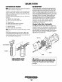
FUEL SYSTEM
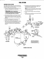
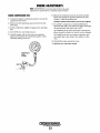
BLEEDING THE FUEL SYSTEM
If the engine cranks but fails to start or starts and then shuts
down, there may be air in the fuel system. Use the following
procedure to purge air from the fuel system.
1. Connect a fuel pressure gauge kit (Snap-On MT 3378) or
equivalent to the Schrader port on the fuel cell.
S. Repeat step 2, this time purging the air completely from
the throttle body. The pressure should be 40psi in the
throttle body after purging the system.
NOTE: The system can develop 40psi without being fully
purged. The system is only fully purged when no bubbles
are visible in ihe purge line.
A CAUTION: Follow the manufacturers
6. Remove the pressure gauge set, and cap all Schrader
Instructions for the safe use of the pressure gauge
kit when purging high pressure fuel systems.
7. Insure that all wire connections are secure and that there
valves.
are no leaks in the, fuel system.
2. While holding the STOP switch in the prime (depress)
position, bleed the air from the fuel celL The fuel cell is
purged when no air bubbles are visible escaping from the
bleed line.
3. Remove the pressure gauge kit from the fuel cell and
connect it to the Schrader valve at the throttle.
4. Open the valve on the fuel pressure gauge line. Do not
prime system without the fuel gauge purge valve open or
air can be forced back into fuel cell. If this happens,
repeat steps 1, 2, and 3 to remove trapped air from the
fuel cell.
-'~onLE
~
'~~~
BODY
--
.....
~
~
PRESSURE
GAUGE
/
/
FUEL CELL
(FUEL PUMP/FILTER)
"SNAP-ON-TOOL" PROVIDES AN
EXCELLENT PRESSURE GAUGE KIT
FOR PRESSURE TESTING AND
BLEEDING SCHRADER TEST PORTS
FUEL FILTER
BLEEDING THE FUEL SYSTEM
Engines &
Genera~rs
15A
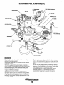
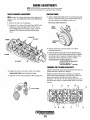
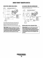
ELECTRONIC FUEL INJECTION (EFI)
FUEL PRESSURE REGULATOR
FUEL RETURN
TO DISTRIBUTOR
AIR HEATER
STEPPER MOTOR
PCVVALVE
AIR SCREEN!
FLAME ARRESTOR
COOLANT RETURN
DESCRIPTION
The injector is a solenoid operated pintle valve that meters
fuel into the intake manifold depending on engine operating
conditions and generator amperage load as determined by the
ECU.
Air flow into the intake manifold is controlled by the ECU
operation of the throttle plate via the actuator. Throttle plate
positioning for proper air flow into the engine is
accomplished through the ECU interpretation of engine
operating conditions. The Schrader valve is used to
monitorlcheck fuel pressure around the fuel injector.
The above illustration shows the throttle body assembly
attached to the intake manifold.
An electronic control unit (BCU) controls the fuel injection
and throttle actuator.
The ECU is supplied with electrical signals it interprets as
engine operating conditions from sensors that monitor intake
air temperature, engine coolant temperature, map sensor
(intake manifold absolute pressure), engine rpm, battery
voltage and distributor cam signal.
The ECU interprets this information to determine the
appropriate injector pulse rate and throttle opening position.
A high pressure fuel pump supplies fuel to the area around
the injector and regulator maintains the fuel pressure in that
area at 35 - 40 PSI.
Engines & Generators
16
ENGINE LUBRICATING OIL
DESCRIPTION
A WARNING: Used engine oil contains harmful
Use a heavy duty engine oil with an API classification of SJ.
Change the engine oil after an initial 50 hours of break-in
operation and every 100 hours of operation thereafter. For
recommended oil viscosity see the following chart:
g Temperature
Above 68° F (20° C)
contaminants. Avoid prolonged skin contact. Clean skin
and nails thoroughly using soap and water. Launder or
discard clothing or rags containing used oil. Discard
used oil properly.
Oil Viscosity
SAE 30. 1OW-3~ or 15W-
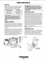
REPLACING THE OIL FILTER
SAE 20 or 10W-30
Below 41° F (5° C)
When removing the used oil filter, you may find it helpful to
punch a hole in the upper and lower portion of the old filter
to drain the oil into a container before removing it. This helps
to lessen spillage. An automotive filter wrench should be
helpful in removing the old oil filter. Place some paper towels
and a plastic bag around the filter when unscrewing it to catch
any oil that's in the filter. Inspect the old oil filter as it is
removed to make sure that the rubber sealing gasket comes
off with the old oil filter. If this rubber sealing gasket remains
sealed against the oil filter adapter, gently remove it. When
installing the new oil filter element, wipe the filter gasket's
sealing surface on the oil filter adapter free of oil and apply a
thin coat of clean engine oil to the rubber sealing gasket on
the oil filter. Screw the filter onto the threaded oil filter stub,
and tighten the filter firmly by hand.
SAE 10W-30
A
CAUTION: Do not allow two or more brands of
engine oil to mix. Each brand contains Its own
additives; additives of different brands could react in
the mixture to produce properties harmful to your
engine.
CHANGING THE ENGINE OIL
The engine oil should be warm. Remove the oil drain hose
from its attachment bracket and lower it into a container and
allow the oil to drain, or attach a pump to the end of the drain
hose and pump the old oil out. Make sure the oil drain hose
is properly secured in its holder after all of the old oil has
been drained.
NOTE: Use genuine WESTERBEKE oil filters. Generic jilters
are not recommended.
Always observe the old oil as it is removed. Ayellow/gray
emulsion indicates the presence of water in the oil. Although
this condition is rare, it does require prompt attention to
prevent serious damage. Call a competent mechanic if water
is present in the oil. Raw water present in the oil can
be the result of a fault in the exhaust system attached to the
engine andlor a siphoning through the raw water cooling
circuit into the exhaust, filling into the engine.
REFILLING THE OIL SUMP
Add fresh oil through the valve cover. After refilling the oil,
run the engine for a few moments while checking the engine's
oil pressure. Make sure there is no leakage around the new
oil filter or from the oil drain system, and then stop the
engine. Then check the quantity of oil with the lube oil
dipstick. Fill to, but not over, the FULL mark on the dipstick.
~8mm [11/16] SOCKET
1/4" NPT
FILTER
OIL SUMP DRAIN
SEALING GASKET
APPLY CLEAN OIL
TIGHTEN BY HAND
Engines & Generators
17
OIL PRESSURE
NOTE: WESTERBEKE recommends that the following engine
adjustments be performed by a competent engine mechanic.
The information below is provided to assist the mechanic.
DESCRIPTION
LOW OIL PRESSURE
The lubricating system is a pressure feeding system using an
oil pump. The engine oil is drawn from the oil sump by the
oil pump, which drives the oil, under pressure, through the
oil filter and various lubricating points in the engine. The oil
then returns to the oil sump to repeat the continuous cycle.
When the oil pressure exceeds the specified pressure, the oil
pushes open the relief valve in the oil pump and returns to
the oil sump, keeping the oil pressure within its specified
range.
The specified safe minimum oil pressure is 4.3 + 1.4 psi (0.3
+ 0.1 kglcm2). A gradual loss of oil pressure usually indicates
worn bearings. For additional information on low oil pressure
readings, see the ENGINE TROUBLESHOOTING chart.
OIL PRESSURE SENSOR
The generator's drive engine has an oil pressure sensor
mounted off the oil gallery. This sensor, during generator
operation, is sending a DC voltage to the ECU that it
interprets as oil pressure. Should the engine's oil pressure
drop below a safe minimum, the DC voltage to the BCU win
drop. The ECD will interpret this as a low oil pressure fault
and stop the generator.
TESTING OIL PRESSURE
To test the oil pressure, remove the oil pressure sender and
install a mechanical oil pressure gauge in its place. After
warming up the engine, set the engine speed at 1800 rpm and
read the oil pressure gauge.
Oil Pressure
Between 55 and 16 psi at 1800 rpm.
Note: A newly started (cold) engine may have an oil
pressure up to 70 or 80 psi. A warmed engine can have an
oil pressure as low as 40 psi. Oil pressure will vary
depending on the load placed on the generator.
MECHANICAL OIL
PRESSURE GAUGE
Oil PRESSURE SENSOR
Engines & Generators
18
REMOTE OIL FILTER (OPTIONAL)
To install, simply remove the engine oil filter and thread on
WESTERBEKE's remote oil filter kit as shown. Always
install this kit with the oil filter facing down as illustrated.
INSTALLATION
This popular accessory is used to relocate the engine's oil
filter from the engine to a more convenient location such as
an engine room bulkhead.
Contact your WESTERBEKE dealer for more infonnation.
NOTE: Refer to ENGINE OIL CHANGE in this manual for
NOTE: Westerbeke is not responsible for engine failure due to
instructions on removing the oil filter.
incorrect installation of the Renwte Oil Filter.
APPLY A THIN COAT OF CLEAN OIL TO THE O-RING WHEN
INSTALLING THIS KIT. THREAD THE KIT ON, THEN HAND
TIGHTEN AN ADDITIONAL
TURN AFTER THE O-RING
CONTACTS THE BASE.
FASTEN SECURELY TO A BULKHEAD
(SCREWS ARE
SUPPLIED)
NOTE: THE "IN"
"OUT" MARKINGS
ON THE ADAPTER WHEN THE HOSES ARE
-REMOVED FOR INSTALLATIONS SO THEY
WILL BE RECONNECTED CORRECTLY.
APPLY A THIN COAT OF
OIL TO THE
ALTER GASKET WHEN INSTALLING. AFTER THE
FILTER CONTACTS THE BASE, TIGHTEN IT AN
ADDITIONAL 3/4 TURN.
Engines & Generators
19
TIMING BELT
DISASSEMBLYIINSPECTION
\\
\~1:'~1"1
III
RUllBEl!
'EXl'OSBl
TENSIONER
PUllEY
(-
... ~
'"
)} ~
UPPER
TIMING BELT
COVER
TIMING BELT
PUllEY
/J
3. Replace the belt if any of the above conditions exist.
TIMING BELT TENSIONER AND IDLER PULLEY
Check the timing belt tensioner and idler pulley for smooth
rotation and abnormal noise. Replace if necessary.
NOTE: Do not clean the tensioner with cleaning fluids.
necessary, use a soft rag to wipe it clean, and avoid
scratching it.
.
lARK THE FORWARD ROTATION
OF THE BELT TO PREVENT
INCORRECT INSTALLATION IF THE
BELT IS TO BE RE·USED.-.-.,..".....
If
/
r
/
TIMING BELT
TENSIONER
TIMING BELT PULLEY AND CAMSHAFT PULLEY
Inspect the pulley teeth for wear, deformation, or other
damage. Replace if necessary.
NOTE: Do not clean the pulley with cleaning fluids.
necessary, use a rag to wipe it clean.
DISASSEMBLY
If
1. Remove the tensioner spring after loosening the
tensioner lock bolt.
2. Remove the timing belt.
NOTE: Do not allow oil or water to contaminate the timing
belt. Do not twist, tum inside out, or bend the belt.
TIMING BELT INSPECTION
1. Replace the timing belt if there is any oil, grease, or
TIMING BELT COVER (LOWER AND UPPER)
moisture on it.
2. Check for damage, wear, peeling, cracks, and hardening.
Replace if necessary.
Inspect the timing belt covers for damage or cracks. Replace
if necessary.
Engines & Generators
20
TIMING BELT
INSTALLATION
DlRECTIO;n
1. Align the timing mark on the timing belt pulley and
camshaft pulley with the marks.
2. Remove all the spark plugs. This is to prevent
compression when rotating the timing belt.
MATING MARK
ARROW
II i
IF RE-USING THE TIMING
BELT, INSTALL IT IN THE
DIRECTION OF THE APPLIED
ARROW - FORWARD ROTATION.
MATING MARK
5. Install the timing belt on the crankshaft pulley and the
camshaft pulley from the tension side (the right side as
viewed from the front of the engine) so that tension is
retained.
6. Loosen the tensioner lock bolt so that the tensioner spring
applies tension.
7. Tum the crankshaft twice in the direction of rotation. This
will apply equal tension to each side of the timing belt.
3. Install the timing belt tensioner and spring.
4. Position the timing belt tensioner all the way to the
intake side, and temporarily secure it by tightening the
lock bolt.
TENSIONER
LOCK BOLT
TIMING BELT
TENSIONER AND SPRING
A
CAUTION: Water or oil on the timing belt
severely reduces the sefJIice life of the belt. keep the
timing belt sproket and tensioner free of oil and grease.
These parts should never be cleaned. Replace if
seriously contaminated with dirt or oil. If oil is evident
on these parts, check the front ease, oil pump seals,
and camshaft oil seals for a possible leak.
Engines & Generators
21
ENGINE ADJUSTMENTS
SPARK PLUGS
DRIVE BELT ADJUSTMENT
The spark plugs should be cleaned and re-gapped after the
first 50 hour break-in period, then inspected every 250 hours
thereafter and replaced as needed.
The drive belts must be properly tensioned. Excessive drive
belt tension can cause rapid wear of the belt and reduce the
service life of the fresh water pump's bearing. A slack belt or
the presence of oil on the belt can cause belt slipping,
resulting in high operating temperatures.
The 22.5Kw and 20Kw SBEG generators have two drive
belts, one drives the governor and alternator and the other
drives the raw water pump. The tension adjustment
procedure for both belts is as follows:
A WARNING: Do not remove the spark plugs while
the engine is hot. Allow the engine to cool before
removing them.
SPARK PLUG GAP: 0.031 - 0.002in. (0.8· 0.7mm).
A
kg-mI.
NOTE: !.octite Anti-Seize applied to the threaded portion of
the spark plugs will retard corrosion, making future removal
of the spark plugs easier.
SPARK PLUG TORQUE: 11 -15 Ib-fl (1.5 -2.31
drive belt's tension while the engine is in operation.
1. Remove the belt gUard.
2. To adjust the governor drive belt, loosen the two governor
INSPECTING
THE SPARK
PLUGS
CHECK FOR DETERIORATION
~
3.
4.
CHECK FOR CARBON
~BUlLD UP AND BURNING
-
i
WARNING: Never attempt to check or adjust the
5.
GAP
HIGH TENSION CORDS (IGNITION WIRES)
Check the ignition wires every 500 operating hours as engine
compartment heat can deteriorate the wires.
Check the resistance of each wire. Do not pull on the wire
because the wire connection inside the cap may become
separated or the insulator may be damaged. When removing
the wires from the spark plugs, grasp and twist the moulded
cap, then pull the cap off the spark plug.
The resistance value is 410 ohm per inch of wire.
6.
7.
mounting bolts.
To adjust the raw water pump/fresh water pump drive
belt, loosen the two raw water pump mounting bolts.
With the belt(s) loose, inspect for wear, cracks, and frayed
edges, and replace if necessary.
To loosen or tighten the governor drive belt, slide the
governor in or out as required, then retighten its mounting
bolts.
To loosen or tighten the raw water pump/fresh water
pump drive belt, slide the raw water pump in or out as
required, then retighten its mounting bolts.
The drive belts are properly adjusted if it can be deflected
no less than 3/8 inch (lOmm) and no more than 1/2 inch
(l2mm) as the belt is depressed with the thumb at the
midpoint between the two pulleys on the longest span of
the belt.
NOTE: Maintain a 221b pressure to the belt's outer face for
proper belt operation. Spare belts should always be
carried on board.
Operate the generator for about 5 minutes then shut down
and recheck the belt(s) tension.
Replace the belt guard.
CHECKING
RESISTANCE
Engines & Generators
22
ENGINE ADJUSTMENTS
NOTE: WESTERBEKE recommends that the following engine
adjustments be performed by a competent engine mechanic.
ENGINE COMPRESSION TEST
6. Measure the compression pressure for all the cylinders.
Ensure that compression pressure differential for each
cylinder is within the specified unit.
1. To check the engine's compression pressure, wann up the
engine then shut it down.
Compression pressure should not differ by more than 14 psi (100 Kpa).
2. Remove the three spark plug caps and remove the three
spark plugs.
7. If a cylinder's compression or pressure differential is
below the limit, add a small amount of engine oil through
the spark plug hole and repeat steps 4 and 5.
3. Install a compression adapter and gauge in the spark plug
hole.
4. Close off the raw water intake seacock.
(a) If additional of oil causes an increase of pressure, the
piston ring and/or cylinder wall may be worn or damaged.
5. Crank the engine with the start motor and unplug the
ignition coil and allow the compression gauge to reach a
maximum reading and record.
(b) If additional oil does not increase compression pressure suspect poor valve contact, valve seizure, or valve
wear.
8. Reinstall three plugs and ignition wires.
9. Open the raw water thm seacock.
COMPRESSION
GAUGE
(TYPICAL)
ADAPTER
~rt:jj
-----~I
Engines & Generators
23
ENGINE ADJUSTMENTS
NOTE: WESTERBEKE recommends that the following engine
adjustments be performed by a competent engine mechanic.
VALVE CLEARANCE ADJUSTMENT
IGNITION TIMING
NOTE: Retorque the cylinder head bolts before adjusting the
engine s valves. See TORQUING THE CYLINDER HEAD
1. Attach a digital timing light to the #1 spark plug and mark
the front crankshaft timing groove and the timing mark on
the scale embossed on the engine's front cover.
BOLTS.
timing mark rl4!J~m!li
1. Remove the rocker cover and gasket.
2. Position the No.1 piston at Top dead Center (TDC) of its
compression stroke and adjust the #1 and #3 exhaust
calves. While facing the front of the engine, rotate the
crankshaft 3600 clockwise and adjust the remaining
valves.
TIMING
GROOVE
/
#1 EXHAUST
#2 INTAKE
CRANKSHAFT
PUllEY
2. Start the engine and warm the engine to its normal
operating temperature.
3. Using the digital timing light, check the ignition timing
first with the vacuum hose disconnected from the distributor and then with it connected. Compare timing with the
specifications below. Adjust the timing as needed.
Timing Specifications: 16" BlOC at 1800 rpm ± 1·
(vacuum advance hose disconnected)
#3 EXHAUST
330 BlOC al1800 rpm ± 10
(vacuum advance hose connected)
TORQUING THE CYLINDER HEAD BOLTS
After the initial break-in period (approximately 50 hours), the
cylinder head bolts should be re-torqued.
3. Replace the rocker cover and the rocker cover gasket.
ROCKER COVER TORQUE: 2.9 - 5:1Ib-fl (0.4 - 0.7 ko-m)
Tighten the cylinder head bolts according to the sequence
shown. Make sure the engine is cold when this is done, and
loosen one head bolt one-half turn and then tighten it
between 43 - 511b-ft (60 - 70 Nm). Then proceed to the next
head bolt in the sequence. Tighten the RS (rocker cover stud)
securely.
4. Adjust all valves to 0.012 (0.30mm) with the engine hot.
4
(O.3Umm)
Engines & Generators
24
GENERATOR INFORMATION
USE OF ELECTRIC MOTORS
Generator Maintenance
The power required to start an electric motor is considerably
more than is required to keep it running after it is started.
Some motors require much more current to start them than
others. Split-phase (AC) motors require more current to start,
under similar circumstances, than otiler types. They are commonly used on easy-starting loads, such as washing
machines, or where loads are applied after the motor is
started, such as small power tools. Because they require 5 to
7 times as much current to start as to run, their use should be
avoided, whenever possible, if the electric motor is to be driven by a small generator. Capacitor and repulsion-induction
motors require from 2 to 4 times as much current to start as
to run. The current required to start any motor varies with the
load connected to it. An electric motor connected to an air
compressor, for example, will require more current than a
motor to which no load is connected.
In general, the current required to stmt 115-Volt motors connected
to medium starting loads will be approximately as follows:
• Maintaining reasonable c1earu.iness is important.
Connections of terminal boards and rectifiers may become
corroded, and insulation surfaces may start conducting if
salts, dust, engine exhaust, carbon, etc. are allowed to
build up. Clogged ventilation openings may cause
excessive heating and reduced life of windings.
• For unusually severe conditions, thin rust-inhibiting
petroleum-base coatings, should be sprayed or brushed
over all surfaces to reduce rusting and corrosion.
• In addition to periodic cleaning, the generator should be
inspected for tightness of all connections, evidence of
overheated tenninals and loose or damaged wires.
• The ikive discs on single bearing generators should be
checked periodically if possible for tightness of screws
and for any evidence of incipient cracking failure. Discs
should not be allowed to become rusty becapse rust may
accelerate cracking. The bolts which fasten the drive disc
to the generator shaft must be hardened steel SAE grade
8, identified by 6 radial marks, one at each of the 6
comers of the head. ,
• The rear armature bearing is lubricated and sealed; no
maintenance is required. However, if the bearing becomes
noisy or rough-sounding, have it replaced.
• Examine bearing at periodic intervals. No side movement
of shaft should be detected when force is applied.If side
motion is detectable, inspect the bearing and shaft for
wear. Repair must be made quickly or major components
will rub and cause major damage to generator.
MOTOR SIZE
(HP)
AMPS FOR
RUNNING
(AMPERES)
AMPS FOR
STARTING
(AMPERES)
1/6
1/4
1/3
1/2
3/4
1
3.2
4.6
5.2
7.2
.10.2
13
6.4 to 22.4'
9.2 to 32.2'
10.4 to 72.8'
14.4 to 29.2*
20.4 to 40.8'
26 to 52
*NOTE: In the above table the maximum Amps for Starting is
more for some small nwtors than for larger ones. The reason
for this is that the hardest starting types (split-phase) are lwt
made in larger sizes.
CARBON MONOXIDE DETECTOR
WESTERBEKE recommends mounting a carbon monoxide
detector in the living quarters. Carbon Monoxide, even in
smaIl amonnts is deadly.
The presence of carbon monoxide indicates an exhaust leak
from the engine or generator or from the exhaust
elbow/exhaust hose, or that fumes from a nearby generator
are leaking in your area.
If carbon monoxide is present, ventilate the area with clean
air and COlTect the problem immediately!
Because the heavy surge of current needed for starting
motors is required for only an instant, the generator will not
be damaged if it can bring the motor tj.p to speed in a few
seconds. If difficulty is experienced in starting motors, tum
off all other electrical loads and, if possible, reduce the load
on the electric motor.
REQUIRED OPERATING SPEED
Run the generator first with no load applied, then at half the
generators capacity, and finally loaded to its full capacity as
indicted on the generators data plate. The output voltage
should be checked periodically to ensure proper operation of
the generating plant and lile appliances it supplies. If an AC
voltmeter or ampmeter is not installed to monitor voltage and
load, check it with a pOltable meter and amp probe.,
NOTE: When the area in which the generatO.r is installed
contains AC equipment O.f 120 volts only, it is recommended
that the generators AC tenni.nal block be configured to
PtPl!ideiO.T~e} 20 yolt A C hot leg for the distribution panel.
111is will ensure good motor starting response from the
generator.
Engines & Generators
25
THE SBEG GENERATOR
SINGLE AND THREE PHASE
DESCRIPTION
CIRCUIT BREAKER
This generator is a four-pole, brushless, self-excited generator
which requires only the driving force of the engine to produce
AC output. The copper and laminated iron in the exciter stator
are responsible for the self-exciting feature of this generator.
The magnetic field produced causes an AC voltage to be
induced into the related excitor rotor windings during rotation.
Diodes located in the exciter rotor rectify this voltage to D<;
and supply it to the windings of the rotating field. This creates
an electromagnetic field which rotates through the windings of
the main stator, inducing an AC voltage which is supplied to a
load. An AC voltage is produced in the auxiliary windings of
the main stator and is, in turn, supplied to a voltage regulator.
The regulator produces a DC voltage to further excite the
exciter stator windings, enabling the generator to produce a
rated AC output. The voltage regulator senses AC voltage output and adjusts DC excitation to the exciter stator winding
according to amperage load the generator is furnishing to
maintain a constant voltage output.
A circuit breaker is installed on all WESTERBEKE
generators. This circuit breaker will automatically disconnect
generator power in case of an electrical overload. The circuit
breaker can be manually shut off when servicing the
generator to ensure that no power is coming into the boat.
NOTE: This circuit breaker is available as a WESTERBEKE
add-on kit for earlier model generators; contact your
WESTERBEKE dealer.
DISC PLATE'
DRIVE HUB
FAN
GENERATOR
HOUSING
GENERATOR
BACK END
DIODE ASSEMBLY
CIRCUIT BREAKER
PTO
Engines & Generators
26
.,
r------
SINGLE PHASE
I
I
I
I
EXCITER
STATOR
REO
----,
----1-----I
I
r
I
I
I
I
I
I
I
EXCITER
ROTOR
1
I
il
i
I
1
I
I
__ J
-----
REO
I
I
ROTOR FIELD
~
--/-------
1.
1._
INTERNAL WIRING SCHEMATICS
r---- -
I
I
I
1
I
I
I
1
-
--1
I
I
STATOR
I
RED
RED
I
AUX
f
J
-----
I
_I
®
W2
®
U1
REGULATOR
~~;===~
FUSE
REO
V1
BLACK
rell ....
~
-
green
yellow "-
GREEN
THem
-e=
RED
Amp
Slab
Volt
~
BLUE
"0
0..
YELLOW
THREE PHASE
-------, 6 WIRE RECONNECTABLE
I
...
I
I
I
!
I
I
I
I
I
1
I
I
I
I
I
EXCITER
. . --
I
I
I
I
I
I
_
I
I
-1--------I
I
I
I
- ~ V2' ~rn~'~K~""""TULft
I
I
r:tcIl
:I~.---+---Ij~
,.....-----, I
f
L. _ _ _ _
I
ROTOR
I
/-_----
1-----'
STATOR
I
I
I
I
I
__~Bl~~~K______
lIT,__~G~REE~N_ _ _ _.Vl
I V2 _.IG§iiiRE§EiENr-tI":. . . . . .
I
:~~ilRmED'-+:II....It+l--~R~ED~----;·WI
:
l~-,,'I
1
I
I
1_. _ _
J
I
_ _ _ ..1
_ _ _ _ _ _ _ _ ..1
L.
""'-'
~
REGULATOR
Q
n:
'"
~
a:
FUSE
6.3 AMP
W
:::J.,
..Jc
(Dw
-'
-VI
I
rea
green
yellow
BLUE
YEllOW
Engines & Generators
27
iii
iI!
<ll
GENERATOR AC VOLTAGE CONNECTIONS
AC VOLTAGE CONNECTIONS
Generator Frequency
NOTE: The frame ground wire (white/green) must be
Frequency is a direct result of engine/generator speed:
1800 rpm 60 hertz; 1500 nnp 50 hertz.
=
properly positioned when changing the AC output
configuration of the AC terminal block. For making
connections to the AC tenninal block, use tenninal ends for
114 inch studs that will accept multi strand copper wire sized
for the amperage rating from the hot lead connection. The
frame ground wire is white or white with a green strip. It
connects between the neutral stud and the generator frame.
=
NOTE: The white/green ground wire may be removed in those
installations where the A C circuit has a separate neutral and
ground circuit. This will prevent the unit from being a ground
source in the vessel.
BE SINtiLE PHASE
120/240V-60HZ.
zAVR r - - - - ___
a::
o
Ci
0
AVR
120V-60HZ.
AVR
AVR
;----.,.
~
..J
!Xl
L1
L2
N
N
A JUMPER IS RE{)UIRED
FOR 120V - 60 Hz
1
I
I
!,
___ J
I
L
---1+-- D10DES/lEDS
REGULATOR
20 KW BED SHOWN
CIRCUIT BREAKER
/
Engines & Generators
28
GENERATOR AC VOLTAGE CONNECTIONS
BE THREE PHASE 6 STUD /12 WIRE TERMINAL BLOCKS
NOTE: For output leads from the AC terminal block used terminal ends/or 114" studs that
accept multi-strand copper wire sized for the average rating from the hot lead connection.
L1
0
L1
L2
0
L2
5
6+7
9
10 + 11
0
L3
--
1 +3
2+3
0
5+7
4
N
L3
N
2-
6+8
9+ 11
8
10+12
12
+
"SERIES YII
0'
"PARALLEL Y"
208V/60 Hz.
480V/60 Hz.
N
L1
L1
"
2+3
L2
0
L2
6+7
L3
0
L3
8+9
10 + 11
2--
0
"PARALLEL DELTAII
"SERIES -DELTA"
l20V/60 Hz.
240V/60 Hz.
"SINGLE PHASE"
L2
L1
4+7
0
6+9
1 + 10
0
8+11
N
-"DOUBLE DELTA"
120-240V/60 Hz.
Engines & Generators
29
GENERATOR AC VOLTAGE CONNECTIONS
DESCRIPTION
BLK AVR
The regulator is equipped with seven numbered terminals (0
to 6) and their related brass jumpers. The illustrations show
connection points and jumpers for the 3 phase configuration
of the generator. The sensing leads connect between pin #1
and pin #2 on the AC terminal block and connection #2 and
#0 on the voltage regulator board.
-N/GND
U1
V1
L1
L2
CASE GND
NOTE: Series Delta requires the installation of a jumper on
the regulator board between terminal B and 10.
L3
BlK AVR
H-i--N/GND
Ul
V1
L1
l2
CASE GND
180·160 V
170·270 V
l3
GRN GND
BE THREE PHASE (SIX WIRE)
3 PHASE VOLTAGE REGULATOR
PARALLEL WYE (STAR)
SERIES WYE (STAR)
SERIES DELTA
Ll
N
L-N -120 VAC 10 60 Hz
L-N -110 VAC 10 60 Hz
L-L .. 450 VAC 30 60 Hz
L-N - 265 VAC 10 60 Hz
BE THREE PHASE (TWELVE WIRE)
L-L - 240 VAC 30 60 Hz
L2, L3-N - 120 VAC 1060 Hz
A. SERIES DELTA - Note the
repositioning of the ground
lead from neutral to generator housing.
J. Jumper using #10 AWG
Wire.
Engines & Generators
30
SBEG TROUBLESHOOTING
NOTE: AC GENERATOR TROUBLESHOOTING MUST
BE PERFORMED WITH THE ENGINE OPERATING AT 60 HZ.
FAULT
PROBABLE CAUSE
NO AC VOLTAGE OUTPUT AT NO LOAD.
1. Short or open in the
main stator winding.
2. Shorted varister
on exciter rotor,
3. Four or more shorted or
open diodes on exciter rotor,
4. Open in exciter
stator winding.
5. Open in rotating
field winding,
RESIDUAL VOLTAGE PRODUCED AT
NO LOAD 15 • 20 VOLTS AC.
1. Blown 6 AMP fuse
auxiliary circuit feed to AVR.
2. Faulty voltage regulator
3. Shorted or open main
stator auxiliary winding.
LOW AC VOLTAGE OUTPUT AT
NO LOAD 60 ·100 VAC.
1. Reset voltage potentiometer.
2. Open or shorted diodes in
exciter rotor 1 to 3 diodes.
3. Faulty voltage regulator
4. Short in rotating field winding.
HIGH AC OUTPUT VOLTAGE
150 VAC OR HIGHER.
1. Faulty voltage regulator.
UNSTABLE VOLTAGE OUTPUT.
1. STB pod on regulator
needs adjustment
AC VOLTAGE DROP UNDER LOAD
60 - 100 VOLTS AC.
1. Diode(s) on exciter rotor
breaking down when load is
applied (inductive) 1·3 diodes.
5. Short in exicter stator.
2. Faulty voltage regulator.
---------.,1
r- -
EXCITER
STATOR
I
I
I
r-----~----------~
I
I
I
I
I
I
I
~_--, I
r-
+
I
EXCITER
ROTOR
I
I
I
I
S I
I
I
I
4 I
I
!
I
I
I
L----- r
t---- ---1
I
A
_________ J
RED
I
I
I
I
!
,-----1 I
L_
ROTOR FIELD
I
I
RED
---
I
STATOR
13
I
I
AUX I ______II
------~
FUSE
RED
®
®U1
W2
6.3 AMP
w
.;::>
.....
."
RED
V1
W1
BLACK
RED
AUXILLIARY CIRCUiT VOLTAGE
215VAC NO LOAD TO Z22VAC FULLY LOADED
BLUE
EXCITER -CIRCUIT VOLTAGE
8.DVDC NO LOAD TO 17.0VDC FULLY LOADED
GREEN
YELLOW
Engines & Generators
31
VOLTAGE REGULATOR ADJUSTMENTS
Description
Stability
The voltage regulator is an advanced design which ensures
optimum AC alternator performance. It is equipped with
complete protection circuitry to guard against operating
conditions that could be detrimental to the AC alternator.
This potentiometer permits variation of the regulator's
response to generator load changes so as to limit
overcompensation and obtain a minimum recovery time to
the normal voltage output.
In order to adjust the regulator stability the alternator must be
running at no-load and the output must be monitored.
Turn the STAB adjust slowly clockwise until the voltage
starts to fluctuate. At this point rotate the STAB adjust
counterclockwise until the voltage is stable within 1 or 2
tenths of a volt.
Amp-Hertz .
These two adjustments are used in conjunction with the two
protection circuits in the voltage regulator that are indicated
by the illumination of a colored LED lights.
!i.a BUS FUSE
PROTECTS THE REGULATOR BOARD 1. Delayed overload protection (yellow LED).
FROM AN ELECTRICAL OVERLOAD
2. Low speed protection (red LED).
Both systems have an intervention threshold which can be
Volts
adjusted using the respective potentiometer. Each of the two
1111s potentiometer is used to adjust output voltage. At proper
circuits are able to cause an adequate reduction in excitor
engine operating speed the output voltage should be held at
voltage to safeguard the excitor windings and prevent their
±1 % from a no-load condition to a full rated generator output
overheating.
and from power factor 1.0 0.8 with engine drive speed
The overload protection system has a delay which permits
variations up to -6%. Prior to starting the engine, turn the
temporary overloading of the generator during times such as
VOLT and STAB trimmers (using a mini phillips screwmotor start-up or other similar load surge demands. The
driver) fully in a counter clockwise (Minimum) direction
regulator also has a third LED (green), that glows during
until you feel them hit their stops. Turn the AMP and HERTZ
generator operation to indicate con-ect operation of the
trimmers completely clockwise (Maximum) in the same
regulator
with the generator.
manner. With the generator running at no-load, at normal
speed, and with VOLT adjust at minimum, it is possible that
output voltage will oscillate. Slowly rotate the VOLT
adjust clockwise. The voltage output of the alternator will
increase and stabilize. Increase the voltage to the desired
value. In this situation, only the green LED will stay lit.
~
~
E
~
...
Hertz
Jlinp
Slab
Volt
i5
n..
VOLTAGE REGULATOR DIAGRAM
Engines & Generators
32
SHORE POWER TRANSFER SWITCH
SHORE POWER CONNECTIONS (60 HERTZ)
120 VOLT/60 HZ THREE WIRE CONFIGURATION
Notice the repositioning of the white wire ground load on the
terminal block to the generator case.
NOTE: Diagram ehows connections for a two-
wire. 120- Volt system. For a three .. wire system
use dotted lit'lt'ts for the other hot leg.
GeneratOt
NOT£: Diagram shows confHtetions for a two-
~
-'"
wlnh 120·Voft system from the generatorl
with three .. wiref t20-VoJt boat system.
,....
III
Ship.to .. Shor. SWitc:h{3 Pole)
PN 32008
{40Ampo,Pol<>,
PN 32009
(90A ..po' Pole)
PN 32010
U25 Amps/ Pole)
PN32133
(200 Amps, Pole)
Slttp~to-Shore
SWiteh{3 Pokt)
PN 32008
(40 Ampsl Pote)
~~~~~
<2]
L'
I
;;:;-+---I---":..:.=-:;=--.... N
~rr-..-.//
If the installer connects shore power to the vessel's AC
circuit, this must be done by means of the Shore Power
Transfer Switch. Set the transfer switch shown in the
diagrams to the OFF position. TJ1is switch prevents
simultaneous connection of shore power to generator output.
~
Ground
Z
(GRN)
,
II.
Ships Load
=~~~:O-VOlt
reNo
Pole)
PN 32010
(125 Ampsl Pole)
PH 32133
(200Amps/Pole)
Equipment
"'"
~~--'
Shore Power
Switching Shore Power to Generator Power
CAUTION: Damage t~ the generator can result if
utility shore power and generator output are connected
at the same time. This type of generator damage is not
covered under the wa«anty; it is the installer's responsibility to make sure all AC connections are co«ect.
A
A
CAUTION: Heavy motor leads should be shut off
before switching shore power to generator power or
vice-versa because voltage surges induced by switchIng
with heavy AC loads on the vessel being operated may
cause damage to the exciter circuit components in the
generator.
Engines & Generators
33
20KW and 22.5KW SBEG GENERATOR
WIRING DIAGRAM #49232
34
20KW AND 22.5KW SBEGA GENERATOR
WIRING DIAGRAM #53467
-1- - - -
~I
~I
I
~.
,
!! ttlt
l
Hi
;a:~~~----*~!§
l
~~ ~>-------"''"'-''''-------------1rn ;
0-,
~
u
j
,i ~
j
I
L
, i~
!
!
~
a~
i
~
,~
ii ~
i
i ! !
~
l
-
3
(
•!•
;
~
,! ;f ~
i
.,, ,, ,,
;
-
-
--'
Engines & Generators
34A
.,,,...,... ,.. , .... ,3
REMOTE START/STOP PANEL WIRING
SCHEMATIC #49209
#180RG
#18 GRN
~-\"--4q:=~--#
18 WHTI BLKIRE D
PART NO. 491.47
#18 WHT/BLK/BLU
a
L1.J
a::
--
::<:::
...J
#20
WHT/BLK/BRN
---
#2'0
WHT/BLK/YEL
ro
#20
co
I-
#
WHT/BLK/GRY
#20 WHT/BLK/GRN
VIEWED FROM WIRE SIDE
#18 WHT/BLK/RED
AVAILABLE FROM YOUR WESTERBEKE DEALER.
WIRING HARNESS EXTENSIONS:
15 fT. PART NO. 49201
30 FT. PART NO. 49211
50 fT. PART NO. 49667
75 fT. PART NO. 49668
100 FT. PART NO. 49669
Engines & Generators
35
ENGINE TROUBLESHOOTING
The following troubleshooting tables are based upon certain
engine problem indicators and the most likely causes of the
problems.
NOTE: The engines control system (electrical system) is
protected by a 8 Ampere manual fuse located on the control
panel. The generator has an AC circuit breaker at the control
panel which should be in the off position when performing
troubleshooting.
When troubleshooting indicates an electrical problem, see the
ELECTRICAL SYSTEM WIRING DIAGRAM as these may
reveal other possible causes of the problem which are not
listed below.
PROBLEM
Engine does not
crank.
Engine starts. runs
but then shuts
down.
Engine starts, runs
but does not come
up to speed.
CAUTION: When servicing or replacing DC
components, tum off the 20 amp DC circuit breaker.
PROBABLE CAUSE
PROBLEM
1. Voltage drop at starter solenoid
terminal.
2. Engine circuit breaker has tripped.
3. aamp fuse/holder is faulty.
4. Battery is low or dead.
5. Loose battery connections.
6. Faulty wire connection.
7. Faulty start switch.
8. Faulty starter relay.
9. Faulty starter solenoid.
10. Raw water filled cylinders.
1. Faulty shutdown switch.
(oil pressure, coolant or exhaust
temperature).
2. Dirty fuel/water separator filter.
3. Faulty speed sensor.
4. Low oi/level in sump.
5. Faulty fuel pump.
6. High engine water or
exhaust temperature.
7. Air in the fuel system.
1. Faulty mag. pick-up sensor.
2. ECU faulty.
3. Fuel pump.
4. Fuel supply to engine restricted.
5. Throttle actuator binding.
6. Actuator or electrical connections
faulty.
7. AC generator overloadJshort.
8. Air intake restricted.
9. Exhaust restricted.
10. Air in fuel system.
Engine cranks but
fails to start.
Engine hunts.
Engine misfires.
Engine backfires.
PROBABLE CAUSE
1. Out of fuel.
2. Engine is flooded.
3. Bad ignition coil.
4. Faulty spark plug.
5. Unplugged distributor wire.
6. Faulty electrical connection.
7. Air in the fuel system.
1. ECU gain adjustment needed.
2. Faulty fuel pump.
3. Mag. pick-up sensor needs adjustment.
4. Low DC battery voltage.
5. Generator overload.
6. Valves need adjustment.
1. Poo r quality fuel.
2. Incorrect timing.
3. Dirty flame arrester.
4. Cracked distributor cap.
5. Faulty ignition wires.
6. Throttle actuator linkage binding.
7. High exhaust back-pressure.
8. Valve clearances are inco rreet.
1. Spark plug wires are connected wrong.
2. Incorrect timing.
3. Engine is flooded.
4. Dirty flame arrester.
Engine overheats.
5. Cracked distributor cap.
6. High exhaust back-pressure.
1. Coolant loss. Pressure test
cooling system. Refill.
Faulty raw water pump impeller.
Belts are loose or broken.
Raw water pump worn.
Faulty thermostat.
2.
3.
4.
5.
6. Heat exchanger restricted.
Engines & Generators
36
ENGINE TROUBLESHOOTING
PROBLEM
PROBABLE CAUSE
PROBLEM
PROBABLE CAUSE
Low oil pressure.
1. Low oil level.
2. Wrong SAE type oil in the engine.
3. Faulty or wrong type oil filter.
4. Relief valve is stuck.
5. Faulty oil pump.
6. Faulty engine bearings.
7. Fau Ity oil filter.
Blue exhaust smoke
discharge from the
engine.
1. Lube oil is diluted.
2. High lube oil level.
3. Crankcase breather hose is clogged.
4. Valves are worn or adjusted
incorrectly.
5. Piston rings are worn
or unseated.
High oil pressure.
1. Dirty oil or wrong SAE type oil in the
Black exhaust smoke
discharge from the
engine.
1. Dirty flame arrester.
2. Lube oil is diluted.
3. Valves are worn or incorrectly
adjusted.
4. Piston rings are worn or unseated ..
5. Cankcase breather hose is clogged.
Poor Performance
at generator speed.
1. Fuel pump clogged. Remove and
replace.
2. Throttle body filter screen dirty.
3. Fuel filter contaminated.
engine.
2. Relief valve is stuck.
No DC charge to the
starti ng battery.
1. Loose/corroded battery charge
Circuit connection(s).
2. Faulty alternator regulator.
3. Faulty DC alternator.
4. Slipping alternator drive belt.
5. Broken alternator drive belt.
CHECK ENGINE LIGHT (YELLOW)
When the Check Engine Light is illuminated, the PC Interface Diagnostics will indicate the problem.
NOTE: To properly troubleshoot the Check Engine light, the PC lnteiface Diagnostics MUST be
used to properly determine the fault cause.
PROBLEM
PROBABLE CAUSE
Wide Band 0 Sensor.
1. Sensor Failure.
2. Sensor wiring issue.
Crossing Stoich.
1. Sensor failure.
2. Sensor wiring issue.
3. Air intake obstructed.
02 Sensor out of range.
1. Air intake obstructed.
2
NOTE: To extinguish the Check Engine Light once the fault is corrected. The unit must be put
through three (3) consecutive successful start and stop sequences, each having a run period of
approximately four (4) running minutes.
Eng/nes & Generators
37
ELECTRICAL TROUBLESHOOTING CHART
The following test procedures will require the use of a multimeter and the
engine's wiring diagram (in this manual). Also refer to the relay testing
page. WESTERBEKE recommends that these tests be peiformed by a
qualified technician. CAUTION: When servicing or replacing DC
components, turn off the 20 amp DC circuit breaker.
PROBLEM
Engine does not crank,. .....
TESTING
(12 VDC is battery + voltage measured to ground)
Test for B+ (12v) at the circuit breaker to the PC
board terminal T4.
IIOK ...
INSPECTION/SOLUTION
Check for bad connections at the engine harness
connector P1, Pin 1, the #14 red wire, or at the
battery + on the starter. Check the connections at
the PC board terminal 4 and at the circuit breaker
Test for B+ (12v) at the circuit breaker to the panel Look for a bad connection from the circuit breaker
fuse end and to the PC board terminal T1.
to the fuse or at the PC board terminal T1.
Replace the circuit breaker.
If OK ...
Test for B+(12v) from the fuse end to the PC board Inspect the connections at the fuse or PC board
terminal T2.
terminal T2. Replace the fuse.
ItOK ...
Test for B+(12v) at the crank relay K1 terminal 30. Check for a bad connection at the engine harness
connector P1, pin #3. Check the DC voltage at
IfOK ...
terminal #30 at the K1, K2, K3 and K4 relays.
Test for B+ (12v) at the starVstop switch terminals Look for bad connections at the panel connector
2 and 10.
82, pin 1, white/black/red wire to the terminal
PC board or at the starVstop switch terminals 2
IIOK ...
and 10.
Test for B+ (12v) at the start switch terminal 1
Replace the start switch.
when the switch is activated.
IIOK ...
Test for B+ (12v) at crank relay K1, terminal 86.
Check bus fuse (8 amp).
If OK ...
ItOK ...
Test for B+(12v) at crank relay K1 terminal 85.
Activate the start switch and after a few seconds
the voltage should drop below .5 volts.
Inspect for a bad connection at relay K1 terminal 8
orange wire or at ECU connector J2, Pin #8
If OK ...
Activate the start switch, after 4-5 seconds B+(12v) Look for a bad connection at relay K1.
should be present at terminal 87 on relay K1.
If OK ...
Activate the start switch, after 4-5 seconds check for Look for a bad connection at crank relay K1,
B+(12v) at the start solenoid.
terminal 85 orange wire or at the ECU
If OK ...
connector J2, pin #8.
Inspect the starter.
Check the connections at crank relay K1 terminal
87, yellow/red wire or at the start solenoid.
Engines & Generators
38
ELECTRICAL TROUBLESHOOTING CHART
The following test procedures will require the use of a multimeter and the
engine's wiring diagram (in this manual). Also refer to the relay testing
page. WESTERBEKE recommends that these tests be performed by a
qualified technician.
PROBLEM
INSPECTION/SOLUTION
TESTING
(12 VDC is battery + voltage measured to ground)
---------------------------Engine cranks but fails to start ...
Test for B+ (12v) at terminals 30 and 86
on the K2 run relay
Check for bad connections at both terminals.
Replace the K2 relay.
If OK •
Test for B+ (12v) at run relay K2, terminal 85 and
activate the start switch. Voltage should be less
than 5 volts.
If OK •
Inspect the connections at relay K2, terminal 85,
or at the ECU connector J2, pin 19.
Activate the start switch, test for B+(12v) at
relay K2 run relay, terminaI8?
Replace the K2 relay.
NOTE: For other possible causes (failure to start) such as fUel pump, speed sensor (MPU),
ignition, etc, refer to the these sections in this manual.
Engine starts, runs but shuts down ..... Test for voltage across the oil pressure sensor
terminals, with the engine running voltage should
be less than 1.0 volts.
IIOK.
Test for voltage across the exhaust temperature
switch, when the engine shuts down, it should
read zero (0) volts.
IIOK.
The engine temperature sensor maybe faulty.
With the PC interface, read the .....
engine shutdown fault
Low DC battery charge level when cranking
IIOK.
Speed loss
IIOK.
Shorted oil pressure sensor
IIOK.
External fault
Faulty oil pressure sensor. Replace sensor/switch.
Faulty exhaust temperature switch. Replace switch.
Loss of coolant thru exhaust elbow.
High exhaust temperature.
Test sensor, refer to component testing in this
manual.
Change batteryi Replace battery.
Check MPU and wiring. Replace MPU.
Check wiring/replace sensor
Check fire suppression system for cause
Engines & Generators
39
LAY-UP & RECOMMISSIONING
GENERAL
Fuel System [Gasoline]
Many owners rely on their boatyards to prepare their craft,
including engines and generators, for lay-up during the
off-season or for long periods of inactivity. Others prefer
to accomplish lay-up preparation themselves.
The procedures which follow will allow you to perform your
own lay-up and recommissioning, or you may use them as a
check list if others do the procedures.
These procedures should afford your engine protection
during a lay-up and also help familiarize you with the
maintenance needs of your engine.
If you have any questions regarding lay-up procedures, call
your local servicing dealer; he will be more than willing to
provide assistance.
Top off your fuel tanks with wzleaded gasoline of 89 octane
or higher. A fuel conditioner such as Sta-Bil ga'loline
stabilizer should be added. Change the element in your
gasoline/water separator and clean the metal bowl. Re-install
and make certain there are no leaks. Clean up any spilled
fuel.
Fuel System [Diesel]
Top off your fuel tanks with No.2 diesel fuel. Fuel additives
such as BioBor and Sta-Bil should be added at this time to
control algae and condition the fuel. Care should be taken
that the additives used are compatible with the primary fuel
filter/water separator used in the system. Change the element
in your primary fuel filter/water separator, if the fuel system
has one, and clean the separator sediment bowl.
Change the fuel filter elements on the engine and bleed the
fuel system, as needed. Start the engine and allow it to run
for 5 - 10 minutes to make sure no air is left in the fuel
system. Check for any leaks that may have been created in
the fuel system during this servicing, correcting them as
needed. Operating the engine for 5 - 10 minutes will help
allow movement of the treated fuel through the injection
equipment on the engine.
Propeller Shaft Coupling [Propulsion Engine]
The transmission and propeller half couplings should always
be opened up and the bolts removed when the boat is hauled
out of the water or moved from land to water, and during
storage in the cradle. The flexibility of the boat often puts a
severe strain on the propeller shaft or coupling or both, while
the boat is taken out or put in the water. In some cases, the
shaft has actually been bent by these strains. This does not
apply to small boats that are hauled out of the water when
not in use, unless they have been dry for a considerable
period of time.
Raw Water Cooling Circuit
Close the through-hull seacock. Remove the raw water intake
hose from the seacock. Place the end of this hose into a five
gallon bucket of clean fresh water. Before starting the engine,
check the zinc anode found in the primary heat exchanger on
the engine and clean or replace it as required, and also clean
any zinc debris from inside the heat exchanger where the
zinc anode is located. Clean the raw water strainer.
Start the engine and allow the raw water pump to draw the
fresh water through the system. When the bucket is empty,
stop the engine and refill the bucket with an antifreeze
solution slightly stronger than needed for winter freeze
protection in your area.
Start the engine and allow all of this mixture to be drawn
through the raw water system. Once the bucket is empty, stop
the engine. This antifreeze mixture should protect the raw
water circuit from freezing during the winter lay-up, as well
as providing corrosion protection.
Remove the impeller from your raw water pump (some
antifreeze mixture will accompany it, so catch it in a bucket).
Examine the impeller. Acquire a replacement, if needed, and
a cover gasket. Do not replace the impeller (into the pump)
until recommissioning, but replace the cover and gasket.
Fresh Water Cooling Circuit [Propulsion Engine]
A 50-50 solution of antifreeze and distilled water is
recommended for use in the coolant system at all times.
This solution may require a higher concentration of
antifreeze, depending on the area's winter climate. Check the
solution to make sure the antifreeze protection is adequate.
Should more antifreeze be needed, drain an appropriate
amount from the engine block and add a more concentrated
mixture. Operate the engine to ensure a complete circulation
and mixture of the antifreeze concentration throughout the
cooling system. Now recheck the antifreeze solution's strength.
Lubrication System
With the engine warm, drain all the engine oil from the oil
sump. Remove and replace the oil filter and fill the sump
with new oiL Use the correct grade of oil. Refer to the
ENGINE LUBRICATING OIL pages in this manual for the
oil changing procedure. Run the engine and check for proper
oil pressure and make sure there are no leaks.
A CAUTION: Do not leave the engine's old engine oil
Intake Manifold and Thru-Hull Exhaust
in the sump over the lay-up period. Lubricating oil and
combustion deposits combine to produce harmful
chemicals which can reduce the life of your engine's
internal parts.
Place a clean cloth, lightly soaked in lubricating oil, in the
opening of the intake manifold to block the opening. Do not
shove the cloth out of sight. (If it is not visible at
recommissioning, and an attempt is made to start the engine,
you may need assistance of the servicing dealer. Make a
note to remove the cloth prior to start-up. The thru-hull
exhaust POlt can be blocked in the same manner.
Engines & Generators
40
LAY-UP & RECOMMISSIONING
Starter Motor
Spare Parts
Lubrication and cleaning of the starter drive pinion is advisable,
if access to the starter permits its easy removal. Make sure the
battery connections are shut off before attempting to remove
the starter. Take care in properly replacing any electrical
connections removed from the starter.
Lay-up time provides a good opportunity to inspect your
Westerbeke engine to see if external items such as drive belts
or coolant hoses need replacement. Check your basic spares
kit and order items not on hand, or replace those items used
during the lay-up, such as filters and zinc anodes. Refer to the
SPARE PARTS section of this manual.
Cylinder Lubrication [Diesel]
Recommissioning
If you anticipate a long lay-up period (12 months or more)
WESTERBEKE recommends removing the fuel injectors for
access to the cylinders. Squirt light lubricating oil into the
cylinders to prevent the piston rings from sticking to the
cylinder walls.
Make sure you have a replacements for the injector and return
line sealing washers.
The recommissioning of your Westerbeke engine after a
seasonal lay-up generally follows the same procedures as
those described in the PREPARATIONS FOR STARTING section regarding preparation for starting and normal starts.
However, some of the lay-up procedures will need to be
counteracted before starting the engine.
1. Remove the oil-soaked cloths from the intake manifold.
2. Remove the raw water pump cover and gasket and
discard the old gasket. Install the raw water pump impeller
removed during lay-up (or a replacement, if required).
Install the raw water pump cover with a new cover gasket.
3. Reinstall the batteries that were removed during the
lay-up, and reconnect the battery cables, making sure the
terminals are clean and that the connections are tight.
Check to make sure that the batteries are fully charged.
Intake Manifold [Gasoline]
Clean the filter screen in the flame arrester, and place a clean
cloth lightly soaked in lube oil around the flame arrester to
block any opening. Also place an oil-soaked cloth in the
through-hull exhaust port, Make a note to remove cloths prior
to start-up!
Cylinder Lubrication [Gasoline]
After engine shutdown, remove the spark plugs and spray a
small amount of fogging oil into each cylinder. Rotate the
crankshaft manually two complete revolutions. Re-install the
spark plugs loosely for winter lay-up.
NOTE: At spring commissioning, remove the plugs and rotate
the crankshaft two full revolutions. Re-install the spark plugs,
tightening properly and connecting the high tension leads fully
onto each spark plug.
Batteries
If batteries are to be left on board during the lay-up period,
make sure that they are fully charged, and will remain that way,
to prevent them from freezing. If there is any doubt that the
batteries will not remain fully charged, or that they will be
subjected to severe environmental conditions, remove the
batteries and store them in a warmer, more compatible
environment
A WARNING: Lead acid batteries emit hydrogen. a
highly-explosive gas. which can be ignited by electrical
arcing or a lighted cigarette. cigar, or pipe. Do not
smoke or allow an open game near the battery being
serviced. Shut all electrical equipment in the vicinity
to prevent electrical arcing during servicing.
0"
Transmission [Propulsion Engine]
A CAUTION: Wear rubber gloves, a rubber apron.
and eye protection when servicing batteries. Lead acid
batteries emit hydrogen, a highly explosive gas. which
can be ignited by electrical arcing or a lighted
Cigarette, cigar, Dr pipe. Do not smoke Dr allow an open
game near the battery being serviced. Shut off all
electrical equipment in the vicinity to prellent electrical
arcing during serviCing.
4. Remove the spark plugs, wipe clean, re-gap, and install to
proper tightness [gasoline].
5. Check the condition of the zinc anode in the raw water
circuit and clean or replace the anode as needed. Note
that it is not necessary to flush the antifreeze/fresh water
solution from the raw water coolant system. When the
engine is put into operation, the system will self-flush in a
short period of time with no adverse affects. It is
advisable, as either an end of season or recommissioning
service, to inspect the area where the zinc is located in the
heat exchanger and clear any and all zinc debris from that
area.
6. Start the engine in accordance with procedures described
in the PREPARATIONS FOR STARTING section of this
manual.
Check or change the fluid in the transmission as required Wipe
off grime and grease and touch up any unpainted areas. Protect
the coupling and the output flange with an anti-corrosion
coating. Check that the transmission vent is open. For
additional information, refer to the TRANSMISSION SECTION.
Engines & Generators
41
WESTERBEKE 25KW AND 22.5KW SBEG GENERATOR SPECIFICATIONS
IGNITION SYSTEM
ENGINE SPECIFICATIONS
Engine Type
Gasoline, four-cycle, four-cylinder,
fresh water-cooled, Vertical, in-line
overhead mechanism
General
Battery ignition 12V negative ground.
Distributor with ignition module and ignitor.
Ignition coil and spark plugs.
Governor
1.5% steady speed regulation.
Distributor
Combustion Chamber
Multi-sphere type.
Solid state type with signal generator and
ignitor.
Bore &Stroke
3.38 x 3.70 inches (86.0 x 94.0 mm).
Spark Plug Thread Size
14mm X1.25 pitch
Piston Displacement
133.26 cubic inches (2184 cubic centimeters)
liming
16° BTDe at 1800 rpm ± .1'
(vacuum advanced disconnection)
Firing Order
1-3-4-2
Direction of Rotation
Clockwise, when viewed from the front
Compression Ratio
8.6:1
Dimensions
Height: 42.2 inches
Width: 22.4 inches
Length: 28.2 inches
Weight
20KW
22.5KW
Inclination
33° BTDC at 1800 rpm ± .1·
(vacuum advanced disconnection)
(1071.9 mm)
(568.9 mm)
(716.3 mm)
Valve liming
.030 inches (0.8 mm)
Dwell
63° at 1800 rpm.
FUEL SYSTEM
General
Electronic fuel injection.
725 Ibs (328 kgs)
7251bs (328 kgs)
Fuel
Regular or unleaded gasoline with an octane
rating of 89 or better.
Continuous 26"
Temporary 30·
Fuel un Pump
Electric-lift capability of 6ft. (1Smm)
Fuel consumption
2.0 - 2.2 U.S. GPH (7.5 - 8.3 LPH) at full output.
Fuel Filter
(on engine)
Replaceable cartridge-screw on.
28.0 psi [2.0 kg/em!})
Air Cleaner
(flame arrester)
Metal screen type cleanable.
Intake Opens 2· BTDC
Intake Closes 53° ABDC
Air Flow
(engine combustion)
69.5 cfm (1.9 cmm)
TUNE-UP SPECIFICATIONS
Compression Pressure
(Limit of difference
between cylinders)
Spark Plug Gap
198.1 psi (14 kg/em!) at 400 rpm
COOLING SYSTEM
Exhaust Opens 57° BBDC
Exhaust Closes -2° ATDC
Valve Seat Angle
Intake 45"
Exhaust 45"
Valve Clearance
(engine warm)
Intake 0.012 inches (0.3 mm)
Exhaust 0.012 inches (0.3 mm)
Engine liming
General
Fresh water-cooled block, thermostaticallycontrolled with heat exchanger.
Operating Temperature
170 -190· F(77 - 88· C)
Fresh Water Pump
Centrifugal type, metal impeller, belt-driven
16° BTDC at 1800 rpm ± .1°
(vacuum advanced disconnection)
Raw Water Pump
Positive displacement, rubber impeller,
belt driven.
EXHAUST EMISSIONS SYSTEMS
Raw Water Flow,
at 1800 rpm
6.7 gpm (25.3Ipm)
System capacity
(coolant)
9.0 qts (S.5Iiters)
EmiSSion Control
Systems
EPA litle 40, part 1048
CARB Title 13, chapter 9, article 4.5
Engines & Generators
42
WESTERBEKE 25KW AND 22.SKW SBEG GENERATOR SPECIFICATIONS
LUBRICATION SYSTEM
General
AC GENERATOR (SINGLE PHASE)
Pressure fed system
General-Single Phase
Brushless six pole, revolving field.
Sealed lubricated single bearing design.
Reconnectable Single phase for 120/240 volts
with solid state voltage regulator
Oil Filter
Full flow, paper element, spin-on type
Sump Capacity
(not including filter)
4.0 U.S. qts (3.7 liters)
plus filter/cooler assembly
Voltage - Single Phase
120 or 120/240 volts - 60 hertz
Operating Oil Pressure
(engine hot)
55-75 psi (3.8 - 5.2 kg/cm 2)
Voltage Regulation
±2% no load to full load.
Oil Grade
API Specification of SJ.
Frequency Regulation
1.5% steady state
Rating (Volts AC)
ELECTRICAL SYSTEM
Starting Battery
12-Volt, (-) negative ground
Battery must be totally dedicated to the
generator and maintained by the generators
own engine DC charging alternator
Battery Capacity
600 - 800 Amps
Starter
12-Volt, (-) negative ground
DC Charging
12-VDC belt driven alternator
2OKW· 60 Hz
120 volts
1021240 volts
166 amps
1661183 amps
22.5KW • 60 Hz
120 volts
1021240 volts
187 amps
187/93 amps
AC GENERATOR (THREE PHASE)
General-3 Phase
GENERATOR COOLING
Air Requirements
(60 Hertz at 1800 RPM)
450 cfm (12.74 cmm)
Engine combustion Air
Requirements
(60 Hertz at 1800 RPM)
69.5 efm (1.9 cmm)
Engine COOling Air
100 cfm (2.83 cmm)
Brushless six pole, revolving field.
Sealed lubricated single bearing design.
12 lead reconnectable for low voltage WYE
and for Delta. Solid state voltage regulator
with protection circuitry.
DC Charging Cranking Amps .175 - 200 amps
Voltage - 3 Phase
(60 Hertz)
Low voltage WYE
High voltage WYE
Delta
208 volts
480 volts
240 volts
2OKW·60Hz
Amperage 3 Phase
Low voltage WYE
High voltage WYE
Delta
70 volts
35 volts
60 volts
22.5KW • 60 Hz
Amperage 3 Phase
Low voltage WYE
High voltage WYE
Delta
86.7 volts
37.6volts
752 volts
Engines & Generators
43
TORQUE SPECIFICATIONS • 20KW AND 22.5KW SBEG GENERATORS
COMPONENT
COMPONENT
FT-LB (M-KG)
FT-lB (M-KG)
Air Cleaner Bracket .................................12.7 -17.4 (1.9 - 2.6)
Main Bearing Cap ....................................56.4 - 60.4 (8.4 - 9.0)
Alternator bracket... .................................25.5 - 35.6 (3.8 - 5.3)
Oil Pan .....................................................4.7 - 8.0 (7.0 - 12.0)
Alternator Flange BoIL ...........................12.7 - 20.8 (1.9 - 3.1)
Oil Pressure Sender .................................9 - 13 (1.2 - 1.8)
Alternator Strap ....................................... 12.7 -17.4 (1.9 - 2.6)
Oil Pressure Switch .................................9 -13 (1.2 -1.8)
Camshaft Pully Lock Bolt... .....................32.2 - 44.3 (4.8 - 6.6)
Oil Pump
M6 ......................................................12.7 -17.4 (1.9 - 2.6)
MB ......................................................25.5 - 35.6 (3.B - 5.3)
Throttle Body ...........................................8.0 - 11.4 (1.2 - 1.7)
Connecting Rod Cap ...............................44.3 - 47.0 (6.6 - 7.0)
Oil Strainer
M6 ......................................................5.3 • B.O (B.O -12.0)
MB ......................................................10.7 -15.4 (1.6 - 2.3)
Coolant Pump .......................................... 12 - 17 (1.6 - 2.4)
Coolant Pump Pulley ...............................12 -17 (1.6 - 2.4)
Rear Cover Assembly ..............................5.3 - 8.0 (8.0 -12.0)
Coolant Temperature Sendor ..................9 13 (1.2 - 1.8)
Rocker Shaft Assembly ...........................12.0 -18.1 (1.8 - 2.7)
Coolant Temperature Switch ...................9 - 13 (1.2 - 1.8)
Spark Plug ...............................................10.0 - 15.4 (1.5 - 2.3)
Crank Shaft Pulley ...................................22.1 - 25.5 (3.3 - 3.8)
Timing Belt Crank Pulley Bolt.. ................120.9 -134.4 018.0 - 20.0)
Cylinder Head
Cold ...................................................55 - 59 (8.2 - 8.8)
Hot ....................................................63 - 67 (9.5 -10.0)
Timing Belt Cover
Upper .................................................4.7 - 6.7 (7.0 -10.0)
Lower .................................................4.7-6.7(7.0 10.0)
Cylinder Head Cover ................................2.6 - 4.0 (4.0 - 6.0)
Timing Tension Lock Bolt... .....................25.5 - 35.6 (3.8 - 5.3)
Drive Plate ...............................................16.1 -18.1 (2.4 - 2.7)
Thermostat Cover ....................................12.7 - 20.8 (1.9 - 3.1)
Exhaust Manifold .....................................12 - 17 (1.6 - 2.4)
Water Pump ............................................12.7 -17.4 91.9 - 2.6)
Front Housing Assembly .........................12.7 -17.4 (1.9 - 2.6)
Intake Manifold... .....................................12 -17 (1.6 - 2.4)
NOTE: Formuffl to convertft-lbs to Nm (Newton Meters) multiply ft-lb x 1.356
Engines & Generators
44
STANDARD AND METRIC CONVERSION DATA
LENGTH-DISTANCE
Inches (in) x 25.4 ::: Millimeters (mm) x .0394 ::: Inches
Feet (ft) x .305 ::: Meters (m) x 3.281 = Feet
Miles x 1.609 ::: Kilometers (km) x .0621 ::: Miles
DISTANCE EQUIVALENTS
1 Degree of Latitude::: 60 Nm ::: 111.120 km
1 Minute of Latitude::: 1 Nm ::: 1.862 km
VOLUME
3
Cubic Inches (in3) x 16.387::: Cubic Centimeters x .061 :::in
Imperial Pints (IMP pt) x .568::: Liters (L) x 1.76::: IMP pt
Imperial Quarts (IMP qt) x 1.137 ::: Liters (L) x.SS ::;: IMP qt
Imperial Gallons (IMP gal) x 4.546 =Liters (L) x .22 =IMP gal
Imperial Quarts (IMP qt) x 1.201 = US Quarts (US qt) x .833 ::: IMP qt
Imperial Gallons (IMP gal) x 1.201 = US Gallons (US gal) x .833 = IMP gal
Fluid Ounces x 29.573 =Milliliters x .034 =Ounces
US Pints (US pt) x .473 ::: Liters(L) x 2.113 ::: Pints
US Quarts (US qt) x .946 =Liters (L) x 1.057 =Quarts
US Gallons (US gal) x 3.785 =Liters (L) x .264
Gallons
MASS-WEIGHT
Ounces (oz) x 28.35 = Grams (g) x .035 ::: Ounces
Pounds (Ib) x .454 ::: Kilograms (kg) x 2.205 = Pounds
PRESSURE
Pounds Per Sq In (psi) x 6.895 = Kilopascals (kPa) x .145 =psi
Inches of Mercury (Hg) x .4912 = psi x 2.036 ::: Hg
Inches of Mercury (Hg) x 3.377 = Kilopascals (kPa) x .2961 ::: Hg
Inches of Water (H20) x .07355 ::: Inches of Mercury x 13.783 ::: H20
Inches of Water (H20) x .03613 psi x 27.684::: H20
Inches of Water (H20) x .248 ::;: Kilopascals (kPa) x 4.026 ::: H20
TORQUE
Pounds-Force Inches (in-I b) x .113 = Newton Meters (Nm) x 8.85 :::in-Ib
Pounds-Force Feet (ft-Ib) x 1.356 Newton Meters (Nm) x .738 ft-Ib
VELOCITY
Miles Per Hour (MPH) x 1.609 =Kilometers Per Hour (KPH) x .621 = MPH
POWER
Horsepower (Hp) x .745 =Kilowatts (Kw) x 1.34 =MPH
FUEL CONSUMPTION
Miles Per Hour IMP (MPG) x .354 = Kilometers Per Liter (Km/L)
Kilometers Per Liter (Km/L) x 2.352 = IMP MPG
Miles Per Gallons US (MPG) x .425 = Kilometers Per Liter (Km/L)
Kilometers Per Liter (Km/L) x 2.352 = US MPG
TEMPERATURE
Degree Fahrenheit e'F) = (OC X 1.8) + 32
Degree Celsius (OC) = (OF - 32) x .56
LIQUID WEIGHTS
Diesel Oil::;: 1 US gallon = 7.131bs
Fresh Water =1 US gallon =8.33 Ibs
Gasoline = 1 US gallon =6.1 Ibs
Salt Water =1 US gallon::: 8.56 Ibs
Engines & Generators
45
METRIC CONVERSIONS
INCHES TO MILLIMETERS
MILLIMETERS TO INCHES
Inches
Inches
mm
Inches
mm
mm
Inches
mm
0.5906
1
25.40
381.00
1
0.0394
15
15
0.7874
0.0787
20
2
50.80
20
508.00
2
76.20
0.1181
25
0.9843
3
25
635.00
3
0.1575
1.1811
4
101.60
30
762.00
4
30
1.3780
127.00
35
889.00
0.1969
35
5
5
40
1016.00
03937
40 ......
1.5748.....10
254.00
10
10 MILLIMETERS::: lCENTIMETER, 100 CENTIMETERS::: 1 METER = 39.37 INCHES (3.3 FEET)
INCHES TO METERS
Inches
Meters
0.0254
0.0508
0.0762
0.1016
0.1270
0.1524
1
2
3
4
5
6
Inches
METERS TO INCHES
Meters
7
8
9
10
11
12
Meters
0.1778
0.2032
0.2286
0.2540
0.2794
0.3048
Inches
0.1
0.2
0.3
0.4
0.5
0.6
3.937
7.874
11.811
15.748
19.685
23.622
Meters
Inches
0.7
0.8
0.9
1.0
1.1
1.2
27.559
31.496
35.433
39.370
43.307
47.244
TO CONVERT METERS TO CENTIMETERS, MOVE DECIMAL POINT TWO PLACES TO THE RIGHT
YARDS TO METERS
Yards
1
2
3
4
5
METERS TO YARDS
Yards
Meters
Meters
Yards
Meters
..
5.48640
1
1.09361
6
6.56168
6
7
6.40080
2
2.18723
7
7.65529
8.74891
8
7.31520 •
3
3.28084
8
4.37445
9.84252
9
8.22960
4
9
5.46807
10.93614
10
9.14400 i
10
5
MOVE DECIMAL POINT FOR HIGHER VALUES - e.g. 6,000 METERS::: 6,561.68 YARDS
Meters
0.91440
1.82880
2.74320
3.65760
4.57200
Yards
------
POUNDS TO KILOGRAMS
kg
Ib
1
2
3
4
5
Ib
0.454
0.907
1.361
1.814
2.268
Gallons
liters
6
7
8
9
10
KILOGRAMS TO POUNDS
kg
kg
2.722
3.175
3.629
4.082
4.536
1
2
3
4
5
Ib
2.205
4.409
6.614
8.818
11.023
GALLONS TO LITERS
-
1
2
3
4
5
3.79
7.57
11.36
15.14
18.93
kg
Ib
13.228
15.432
17.637
19.842
22.046
6
7
8
9
10
LITERS TO GALLONS
Gallons
Liters
Liters
Gallons
10
20
30
40
50
37.86
75.71
113.57
151.42
189.28
1
2
5
10
20
0.26
0.53
1.32
2.64
5.28
PINTS TO LITERS
Gallons
Liters
60
90
120
150
180
15.66
23.n
31.32
39.62
47.54
LITERS TO PINTS
Pints
Liters
Pints
Liters
Liters
1
2
3
4
5
0.47
0.95
1.42
1.89
2.37
6
7
8
9
10
2.84
3.31
3.79
4.26
4.73
1
Pints
2.11
4.23
6.34
8.45
10.57
2
3
4
5
liters
Pints
12.68
14.79
16.91
19.02
21.13
6
7
8
9
10
TEMPERATURE
32
I
40
I
50
I
60
I
70
I
75
I
85
I
95
I
105 140
I
I
I
I
I
I
I
I
I
I
I
I
0
5
10
15
20
25
30
35
40
60
Engines & Generators
46
175 212
I
I
I
OF
I
80 100
°C
SUGGESTED SPARE PARTS
WESTERBEKE MARINE GENERATORS
CONTACT YOUR WESTERBEKE DEALER FOR SUGGESTIONS AND ADDITIONAL INFORMATION
ZINC ANODES
FUEl/WATER SEPARATOR
FILTER ELEMENT
HEAT EXCHANGER
END GASKET
THERMOSTAT
AND GASKET
FUEl FilTER
OIL FilTER
SPARE FUSES
DRIVE BElTS
CONTROL PANEL AND
BE REGULATOR
WESTERBEKE RECOMMENDS CARRYING ENOUGH SPARE
ENGINE OIL (YOUR BRAND) FOR AN OIL CHANGE (5 DTS.)
AND A GALLON OF PREMIXED COOLANT.
SPARE PARTS KITS
Kit B
WESTERBEKE also offers two Spare Parts Kits, each
packaged in a rugged hinged toolbox.
Kit A includes the basic spares.
Kit B is for more extensive off-shore cruising.
Impeller Kit
Water Pump Repair Kit
Thermostat Kit
Zinc Anodes
Complete Gasket Kit
Heat Exchanger Gaskett
Kit A
Impeller Kit
Heat Exchanger Gasket
Oil Filter
Oil Filter
Drive Belt
Spark Plugs
Drive Belt
Zinc Anodes
Spark Plugs
Engines & Generators
47
/w/WESTERBEKE
/GENERATORS
SAFE
CO
SERIES
WESTERBEKE CORPORA TION • MYLES STANDISH INDUSTRIAL PARK
150 JOHN HANCOCK ROAD, TAUNTON, MA 02780-7319 U.S.A.
TEL: (508) 823-7677· FAX: (508) 884·9688 .,Website: www,westerbeke,com
1078DW/SC1204