1
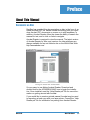
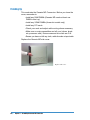
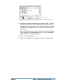
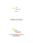
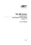
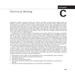
Genesis MP
Conversion Guide
DayStar Digital, Inc.
Technical Support Department
5556 Atlanta Highway
Flowery Branch, GA 30542
770-967-2077 fax: 770-967-3018
http://daystar.com/
81-00610
Preface
About This Manual
Documents on Disc
DayStar has provided this documentation on disc in the form of an
Adobe Acrobat PDF file. Adobe Acrobat technology lets you reproduce Acrobat PDF documents on screen or in print anywhere. In
addition, Acrobat Reader offers the viewer the ability to search the
manual for text, and to click on links to navigate.
Acrobat Reader is required to view the manual. The latest version
of Acrobat Reader for Mac, and versions for other platforms are
always available for free on Adobe’s site on the World Wide Web:
http://www.adobe.com/
Viewing the manual with Acrobat Reader
It’s very easy to use Adobe Acrobat Reader. Download and
double-click on the ACROREAD.MAC icon to begin the installation. Once installed, read the “Help-Reader.pdf” file for more information on getting around with Acrobat.
If you would like to create a printed manual, Acrobat may be used
to reproduce a hard copy with your laser printer. Consult the “HelpReader.pdf” file for information on printing from Acrobat Reader.
Genesis MP
About This Manual
◆3
Chapter 1
Conversion Basics
Introduction
DayStar has designed the Genesis MP Conversion Kit to make
converting your Power Macintosh to a Genesis MP as easy as
possible. This manual has been organized into chapters on disassembly of the various Power Macintosh models, and assembly of
the Genesis MP Conversion.
We recommend that you read and understand this chapter, and all
of the procedures covering disassembly of your Power Macintosh
and assembly of the Genesis MP Conversion before beginning.
We have done everything possible to make the conversion
process easy enough for any user to accomplish in a few hours
with a minimum of tools. No specialized knowledge is required,
and this manual guides you step-by-step through the entire
process.
If you read through the procedures and do not feel that you can or
should attempt the conversion yourself, please contact your local
authorized service facility to arrange for conversion for a modest fee.
Upgrading your Motherboard
∆
!
The motherboards of some Power Macintosh models must be
upgraded by DayStar Digital for use in the Genesis MP
Conversion Kit. To upgrade your motherboard, consult the information shipped with your conversion kit.
IMPORTANT:
Contact DayStar to arrange for your upgrade before beginning the
conversion process.
The Conversion Process - an Overview
To convert your Power Macintosh to a Genesis MP, you must follow five basic steps:
Step 1 - Prepare for the Procedure
Step 2 - Disassemble your Power Macintosh
Step 3 - Send your motherboard to be upgraded (if required)
Step 4 - Assemble your Genesis MP Conversion
Step 5 - Install the Genesis MP Software
Genesis MP
Conversion Basics
◆5
This chapter covers Step 1: Preparation. To make sure your conversion proceeds as easily as possible, you need to prepare an
appropriate work area and gather the right tools. You also need to
familiarize yourself with the contents of the kit, with electrostatic
discharge safety and basic mechanical information, and read and
understand the procedures you’ll follow. If your motherboard needs
to be upgraded, you will arrange for the upgrade at this time.
Step 2 is covered in the chapters on disassembly of the various
Power Macintosh computers. You will disassemble your computer,
keeping the motherboard, RAM, storage devices and peripherals
and other components for reuse in the Genesis MP conversion.
Step 3, upgrading the motherboard, is covered in the literature
which shipped with the Genesis MP Conversion Kit. If you are
unsure of whether your motherboard needs to be upgraded, contact DayStar to determine how to proceed.
Step 4, assembly of the Genesis MP Conversion, is covered following the disassembly chapters. You will prepare your storage
devices for reinstallation, install them and your motherboard into
the Genesis MP Chassis. You’ll reinstall your peripherals and add
DayStar’s nPOWER multiprocessor card.
In Step 5, the final chapter of this guide, we’ll tell you how to install
DayStar’s multiprocessing software and start up and test your new
Genesis MP Conversion.
About Electrostatic Discharge (ESD)...
∆
!
CAUTION
The Genesis MP and your Power Macintosh use electronic components that are sensitive to static electricity. Use care when handling and installing these components to prevent damage which
can be caused by static currents. Always work in an area of low
static electricity on a grounded surface to prevent static discharge.
If you’ve ever been shocked when touching a doorknob on a dry
winter day, you’ve experienced ESD. For humans, the experience
of ESD is an annoyance. For sensitive microcircuitry, it’s devastating. A shock too small to feel can wipe out hundreds of dollars of
RAM memory, thousands of dollars of processor chips.
Static electricity can be discharged from yourself or from a conductor, possibly destroying static-sensitive devices or microcircuitry. Often, static discharge may not be detected by sight, touch, or
sound, although damage occurs.
An electronic device exposed to ESD may fail immediately, gradually, or not at all - it’s impossible to know whether damage has
occurred until the device stops operating correctly.
6◆
Chapter 1 - Conversion Basics
Genesis MP
As you work, it is important to minimize static buildup. Static
charge can build to dangerous levels by:
• Working in extreme low humidity
• Walking across carpet with a static sensitive device
• Walking across a vinyl floor
• Body motion within an unprotected ESD work area
• Removing devices from plastic packaging
• Removing devices from vinyl packaging
• Removing devices from Styrofoam packaging
• Removing devices from bubble-wrap packaging
∆
!
• Packing or Unpacking devices wrapped in foam
IMPORTANT
DayStar provides an anti-static wrist strap with each Genesis MP.
A properly worn and grounded strap drains static buildup to
ground, minimizing the danger of ESD while you are wearing it.
The strap is to be used for grounding yourself while working with
the static sensitive components of your system. Static sensitive
components include any components which have microcircuitry,
including motherboards, RAM, processor cards PCI cards, disk drives, CD-ROM drives, floppy drives, audio/video cards and most
other peripherals.
Do not attempt the Genesis MP Conversion before you have located, grounded and put on the strap.
Creating an ESD Safe Work Area
∆
!
IMPORTANT!
Many electronic devices are ESD sensitive. Be sure to take the following precautions when handling an electronic device:
• Always wear an anti-static wrist strap
• Never attempt installation on a carpeted floor
• Never wear leather shoes (rubber soles are recommended)
• Never attempt installation in an overly dry environment
• Never wear silk or polyester clothing during an installation
• Always remove all jewelry (i.e., rings, bracelets, watches, etc.)
• Always transport electronic devices in static-safe containers:
(tubes, bags, boxes)
• Always protect parts and assemblies with conductive ESD
approved containers and/or packaging
Genesis MP
Chapter 1 - Conversion Basics
◆7
• Always remove electronic devices in a grounded work area
• Always use tools (i.e., screwdrivers, snips, vacuums) that
are conductive.
Grounding Using The Anti-static Wrist Strap
To ensure proper grounding, the antistatic wrist strap must be
worn in direct contact with the skin. Attach the free end of the strap
to a good electrical ground in accordance with the instructions and
precautions printed on the label.
Good electrical grounds include cold water pipes (where conductive pipe extends to ground - plastic pipe and metal pipe connected to plastic pipe are not appropriate), grounded electrical conduit,
the back of properly connected and grounded outlet strips and
exposed metal on other properly grounded equipment.
The anti-static wrist strap grounds your body. When working on an
unplugged system, ground yourself with the wrist strap and touch
a safe area of exposed metal on the system’s power supply before
touching any static-sensitive components in the case. This brings
the equipment to the same static potential as your body, eliminating the possibility of ESD. Be sure to touch the power supply each
time you resume work inside any system.
Preventing Damage to Disk Drives
To prevent ESD and physical shock damage to floppy diskette
drive and/or hard disk drive(s), ensure the following safety precautions:
• Always utilize anti-static techniques when handling drives
• Always re-package drives in their original shipping packaging
• Never drop a drive onto any surface (hard/or soft)
• Shield work surface with a minimum of 1-inch shock-proof
foam
• Always place a drive metal-side down (electronic-side up) on
shock-proof foam
8◆
Chapter 1 - Conversion Basics
Genesis MP
Work Area
Prepare a suitable work area before beginning disassembly. This
should include a large, sturdy flat surface where you can work on
both machines in a comfortable position. Make sure you have adequate lighting, and make provisions for grounding the provided
anti-static strap. Choose an area without carpet to limit static
buildup and to make it easier to find dropped fasteners.
Remove all external cables from the Power Macintosh before
beginning disassembly. Ground the anti-static wrist strap and
make sure you have available the large anti-static bag for the
motherboard before you begin. Resealable plastic bags or film
canisters are handy for holding small parts.
Tools Required
• #2 Phillips Head Screwdriver
• Torx™ T-8 Driver (7500, 7600 and 8500 only)
• Small flathead screwdriver
Included with this Kit:
1 Genesis MP Conversion Chassis
1 nPOWER Multiprocessor Card
1 Internal SCSI Cable
1 Floppy Disk Drive Cable
1 CD-ROM Audio Cable
1 Large Antistatic Bag for Motherboard
1 Motherboard Box with Foam
7 3.5" Drive Rail Pairs with Screws
3 5.25" Drive/Floppy Drive Rails with screws
1 Genesis MP CD-ROM
1 Genesis MP Boot Disk (floppy disk)
2 Keys for Locking Panel
1 Disposable Anti-Static Wrist Strap
1 Bag of Motherboard Screws
1 Bag of Spare Motherboard Screws
1 Genesis MP User Guide
Genesis MP
Chapter 1 - Conversion Basics
◆9
Before You Begin...
To make your conversion go smoothly, follow the checklist below:
• If your Conversion Kit included directions for upgrading your
motherboard, contact DayStar to arrange for the upgrade.
• Check the structure of your hard disk with Apple’s Disk First
Aid before beginning. Perform any needed disk repair before
beginning the conversion.
• Back up all hard disks before beginning the conversion.
• Prepare a convenient, ESD-safe work area.
• Make sure you have received all the necessary components
and software.
• Identify and read the appropriate procedures for the disassembly of your Mac and the assembly of the Genesis MP
Conversion before proceeding.
• Make sure you have adequate time to convert before proceeding. Since your Mac will not be available until the conversion is complete, finish any pressing deadline work
before beginning the conversion.
• Complete and test the Genesis MP Conversion before
adding new upgrades to the software or hardware; it is difficult to troubleshoot more than one new upgrade at a time.
Contacting DayStar
If you need technical assistance with the Genesis MP Conversion,
you should contact your authorized reseller or service center. If
you need further assistance, or if you have other questions, you
may contact DayStar at:
DayStar Digital
5556 Atlanta Highway
Flowery Branch, GA 30542
770.967.2077
email:
[email protected]
World Wide Web:
http://daystar.com/
10 ◆ Chapter 1 - Conversion Basics
Genesis MP
Chapter 2
Disassembling the Power Macintosh 8500 or 9500
Getting Started...
The Power Macintosh 8500 and 9500 are housed in nearly identical tower cases. The 9500 case is taller, the motherboard has
more PCI and DIMM slots, and there is a cooling fan for the PCI
card area. The 8500, by contrast, has an Audio/Video (AV) module
which must be unplugged and removed for reuse.
The Power Macintosh 8500
Genesis MP
The Power Macintosh 9500
Disassembling the Power Macintosh 8500 or 9500
◆ 11
The Power Macintosh 8500 (rear)
The Power Macintosh 9500 (rear)
Because of the similarity of the machines, most disassembly steps
are identical. Most of the photos feature a Power Macintosh 9500.
We will call your attention to the very few special procedures for
disassembly of the 8500 when those steps are reached.
You will be re-using the motherboard, RAM DIMMs, VRAM DIMMs
(8500 only), floppy disk drive, hard drive(s), CD-ROM drive,
Audio/Video (AV) module and screws (8500 only), and any
installed peripherals. You must wear the provided anti-static wrist
strap once you open the machine’s case.
Please read and understand the disassembly procedure before
beginning disassembly of the unit. Also, read and understand the
chapter: Conversion Basics, especially the section on
Electrostatic Discharge.
Tools Required
• #2 Phillips Head Screwdriver
• Torx™ T-8 Driver (8500 only)
• Small flathead screwdriver
12 ◆ Chapter 2 – Disassembling the Power Macintosh 8500 or 9500
Opening the Case
To open the 8500/9500 case, disconnect all external cables and
loosen the captive screws securing the cover...
Loosen the captive screws
separate the cover from the chassis with gentle finger pressure...
Separate the cover from the chassis
Genesis MP
Chapter 2 – Disassembling the Power Macintosh 8500 or 9500
◆ 13
then spread the sides of the cover apart slightly and lift the cover
forward, up and off.
Spread the sides slightly and remove the cover
Removing PCI cards and Processor Card
Open the card support to obtain access to the PCI and processor
card slots. The 9500 card support contains a cooling fan which
gets its power from the motherboard.
Opening 9500 fan/card support
14 ◆ Chapter 2 – Disassembling the Power Macintosh 8500 or 9500
The 8500 card support does not have a fan.
Opening 8500 card support
Disconnect any cables attached to the PCI cards if you have not
already done so.
Remove any PCI cards (if installed) by spreading apart the retainer tabs and pulling the card out of the slot. If necessary, wiggle the
card left and right a little bit to free it up. Do NOT stress the card
up and down - this could damage the card and the PCI connector.
Set PCI card(s) aside for reuse in the Genesis MP Conversion.
Remove installed PCI card(s)
Remove the processor card and set it aside. You will not reuse the
processor card in the Genesis MP Conversion.
Remove processor card
Genesis MP
Chapter 2 – Disassembling the Power Macintosh 8500 or 9500
◆ 15
Unplug the PCI Cooling Fan (9500 only)
The PCI cooling fan in the 9500’s card support connects to the
motherboard through a short cable. Follow the cable to the connector on the motherboard and disconnect it. The fan will not be
reused in the Genesis MP Conversion. The 8500 card support
does not have a PCI cooling fan.
PCI cooling fan connector
Remove the Audio/Video (AV) Cable (8500 only)
Remove the AV cable from its connector (located near the 8500’s
processor card slot). Use care - the AV cable is delicate and the
cable and module will be reused in the Genesis MP.
Remove the AV cable
16 ◆ Chapter 2 – Disassembling the Power Macintosh 8500 or 9500
Remove Cables from the Motherboard
There are six cables connected to the top of the motherboard. They
are (from left to right in the photo below): motherboard 3.3v power,
floppy disk drive, CD-ROM audio, speaker, motherboard main
power, and internal SCSI. Remove them at this time, referring to the
photos below. None of these cables are reused in the Genesis MP
Conversion.
Remove these six cables
Pull the SCSI cable straight up by its handle.
Remove the SCSI cable
Genesis MP
Chapter 2 – Disassembling the Power Macintosh 8500 or 9500
◆ 17
The two power supply connectors lock into place with a latch. Mild
thumb pressure will lift the latch and allow removal of the connector, as illustrated below.
Remove the motherboard
main power cable
Remove the speaker cable. Note the positive locking latch at the top
of the connector in the photo below. If the connector is stubborn,
wiggle it left and right while pulling.
Remove speaker cable
Remove the floppy disk drive cable by pulling the attached tab.
Remove floppy disk drive cable
18 ◆ Chapter 2 – Disassembling the Power Macintosh 8500 or 9500
Remove the motherboard 3.3v power cable. Press the locking
mechanism to release the cable.
Remove motherboard 3.3v cable
Remove the CD-ROM audio cable. You will probably find it easiest
to remove the cable from the CD-ROM drive at this time and
remove it from the motherboard once the motherboard has been
removed from the chassis.
Remove CD-ROM audio cable
from CD-ROM drive
Genesis MP
Chapter 2 – Disassembling the Power Macintosh 8500 or 9500
◆ 19
Remove the plastic power switch/LED holder from the chassis by
pressing the retaining tabs and pressing the switch forward and
out of the machine. Let the holder hang to provide slack for
removal of the motherboard. In some cases, you will be able to
remove the LED from the LED holder to free the motherboard. The
LED and plastic power switch will not be used in the Genesis MP
Conversion.
Remove plastic power switch/LED holder
Provide slack for removal of motherboard
20 ◆ Chapter 2 – Disassembling the Power Macintosh 8500 or 9500
Removing the Motherboard
∆
!
∆
!
The motherboard and tray are held in with one central screw, one
latching tab and several sliding hooks built into the case. Removal
is a matter of removing the central screw, then lifting the latching
tab and sliding the motherboard tray forward to allow release of
the tray and motherboard from the case. The motherboard may
then be removed from the motherboard tray.
CAUTION
The motherboard is delicate - handle it with care. Make sure you
are wearing the provided ground strap and observing ESD (electrostatic discharge)-safe procedures as described in the
Conversion Basics chapter of this manual. Prepare the supplied
anti-static bag before you remove the motherboard, and place the
motherboard in the anti-static bag immediately upon removal to
keep it safe from damage by ESD.
IMPORTANT
The motherboard should come out very easily if you follow the
instructions below. If you are having difficulty removing the motherboard, use caution; you may not have everything disconnected.
Review the instructions to make sure you’ve followed all the steps
and try again.
Remove the central screw holding the motherboard in place. The
screw is located in the center of the plastic motherboard tray.
Remove the central screw
Genesis MP
Chapter 2 – Disassembling the Power Macintosh 8500 or 9500
◆ 21
Note the latching tab and the notch in the motherboard near the
top motherboard hook.
Lift latching tab (1). Align hook
with notch (2)
Lift the latching tab and slide the motherboard forward until the top
motherboard hook is centered in the notch in the motherboard.
Lift the latching tab and
slide the motherboard forward
Tilt the motherboard out from the top and lay it flat on the work
surface, taking care not to put undue stress on the LED cable (if
still connected).
Remove motherboard by tilting
out from the top
22 ◆ Chapter 2 – Disassembling the Power Macintosh 8500 or 9500
If the LED cable is still connected, remove it now.
Remove the LED cable
∆
!
If needed, apply leverage gently with a small flathead screwdriver.
CAUTION
It is possible to break the LED connector by applying more than
gentle leverage. Use care.
Use gentle leverage if needed
Remove the CD-ROM audio cable if still attached.
Remove CD-ROM audio cable
Genesis MP
Chapter 2 – Disassembling the Power Macintosh 8500 or 9500
◆ 23
Remove the motherboard tray from the motherboard by lifting the
two latches...
Unlatch the motherboard tray...
...and tilting the tray off. The tray will not be reused in the Genesis
MP Conversion.
...and tilt the tray off
∆
!
Immediately place the motherboard in the provided anti-static bag
to protect it from damage by electrostatic discharge (ESD).
IMPORTANT:
If your motherboard is to be upgraded by DayStar, consult the literature included with your Genesis MP Conversion for important
information about preparing your motherboard for shipment.
Place motherboard in
anti-static bag
24 ◆ Chapter 2 – Disassembling the Power Macintosh 8500 or 9500
Removing Storage Peripherals
You will be removing and reusing the CD-ROM drive, floppy disk
drive, hard disk drive(s) and any installed internal SCSI peripherals
in the Genesis MP Conversion. The drive carrier trays will not be
reused and must be removed.
Remove the SCSI cable from the CD-ROM drive...
Remove CD-ROM SCSI cable
...then remove the power cable.
Remove CD-ROM power cable
Remove the CD-ROM drive by lifting the latching tab at the front of
the drive and pulling the drive forward until it is released from the
chassis. Set the drive aside - it will be reused in the Genesis MP
Conversion.
Remove the CD-ROM drive
Genesis MP
Chapter 2 – Disassembling the Power Macintosh 8500 or 9500
◆ 25
Unlatch the drive bay support to provide access to the floppy disk
drive cable
Unlatch the drive bay support
Remove the floppy disk drive cable.
Remove the floppy drive cable
Remove the floppy drive by pressing the release latch and pushing
the drive forward and out of the machine. Set the floppy disk drive
aside - it will be reused in the Genesis MP Conversion.
Remove the floppy disk drive
26 ◆ Chapter 2 – Disassembling the Power Macintosh 8500 or 9500
Unplug the hard drive power cable from the rear of the hard drive
Unplug hard drive power cable
Unplug the hard drive SCSI cable from the hard drive.
Unplug hard drive SCSI cable
Remove the hard drive by pressing the latching tab and pulling the
drive forward, out of the chassis.
Remove hard drive
Genesis MP
Chapter 2 – Disassembling the Power Macintosh 8500 or 9500
◆ 27
Remove the floppy disk drive carrier tray by removing the four
screws and lifting it off. The drive tray is not reused in the Genesis
MP Conversion.
Remove the floppy drive tray
Remove the floppy disk drive EMI shielding (sometimes held on by
tape - remove the tape). The EMI shielding is not reused in the
Genesis MP Conversion.
Remove floppy disk EMI shield
Remove the hard drive carrier tray by removing the four screws and lifting the tray off. The carrier tray is not reused in the Genesis MP
Conversion.
Remove hard drive tray
28 ◆ Chapter 2 – Disassembling the Power Macintosh 8500 or 9500
Remove the CD-ROM drive carrier tray by removing the four screws
and lifting the tray off. The carrier tray is not reused in the Genesis MP
Conversion.
Remove the CD-ROM tray
Removing Audio/Video (AV) Module (8500 only)
Using a Torx™ T-8 driver, remove the two screws holding the AV
module in place. Remove the AV module from the inside of the
8500 case.
Remove the AV module
Save the AV module and screws - they will be reused in the Genesis MP.
Genesis MP
Chapter 2 – Disassembling the Power Macintosh 8500 or 9500
◆ 29
Wrap-Up...
This concludes disassembly of the Power Macintosh 8500 or
9500. Before continuing with assembly of the Genesis MP, check
to ensure that you have all of the components from the 8500 or
9500 that will be reused in the Genesis MP:
• Power Macintosh Motherboard (in anti-static bag)
• Any previously installed RAM DIMMs
• Any previously installed PCI cards
• Hard drive(s) and other internal SCSI devices
• Floppy drive
• CD-ROM drive
• AC Power Cord
• Any previously installed VRAM DIMMs (8500 only)
• AV module and screws (8500 only)
• L2 Cache (socketed on 8500 only)
If your motherboard requires an upgrade, consult the upgrade literature that came with your Genesis MP Conversion for details on
preparing the motherboard for shipping. Motherboards requiring
upgrades must be upgraded before assembly of the Genesis MP
Conversion.
30 ◆ Chapter 2 – Disassembling the Power Macintosh 8500 or 9500
Chapter 3
Disassembling the Power Macintosh 7500 or 7600
Getting Started...
The Power Macintosh 7500 and 7600 are identical in terms of
disassembly. All steps in this section refer both machines.
Disassembly of the Power Macintosh 7500 or 7600 is quite easy; it
is possible to access all components with a minimum of tools.
The Power Macintosh 7500
(7600 is similar).
You will be re-using the motherboard, RAM and VRAM DIMMs,
floppy disk drive, hard drive(s), CD-ROM drive, Audio/Video (AV)
module and screws, cache (if equipped) and any installed peripherals. You must wear the provided anti-static wrist strap once you
open the 7500/7600 case.
Please read and understand the disassembly procedure before
beginning disassembly of the unit. Also, read and understand the
chapter: Conversion Basics, especially the section on
Electrostatic Discharge.
Tools Required
• #2 Phillips Head Screwdriver
• Torx™ T-8 Driver
• Small flathead screwdriver
Genesis MP
Disassembling the Power Macintosh 7500 or 7600
◆ 31
Opening the Case
To open the Power Macintosh 7500/7600 case, disconnect all
external cables, squeeze the release buttons on the front panel
and pull the case cover forward, then up and off as illustrated by
the photos below.
Squeeze the release buttons...
and pull the cover
forward, up and off
32 ◆ Chapter 3 – Disassembling the Power Macintosh 7500 or 7600
Genesis MP
Accessing the Motherboard
Open the PCI card support cover and the drive bay/power supply
carrier stand as shown in the photo below. Note that the carrier
stand latches into the chassis when fully open.
Open the PCI card support
cover and drive bay/power
supply support stand
Open the latches holding the drive bay/power supply carrier by
flipping them toward the inside of the 7500/7600 chassis as shown
in the photo below.
Flip open the latches
Open the drive bay/power supply carrier by swiveling it out.
Open the carrier
Genesis MP
Chapter 3 – Disassembling the Power Macintosh 7500 or 7600
◆ 33
Set the prop support so that it clicks into the hole in the case.
Set the prop
∆
!
NOTE:
The prop prevents the drive bay/power supply carrier from tipping
back into the case. However, if you pick the 7500/7600 case up
with the drive bay/power supply carrier open, the carrier will tip
outside of the case. If possible, leave the 7500/7600 flat on a table
for the duration of the disassembly.
Remove the Processor Card
Remove the processor card by pulling it straight up and out of the
7500/7600 motherboard. Remove any installed PCI cards at this time.
Set aside PCI cards for re-use. The processor card is not re-used.
Remove the processor card
34 ◆ Chapter 3 – Disassembling the Power Macintosh 7500 or 7600
Genesis MP
Remove Cables from the Motherboard
There are 8 cables connected to the 7500/7600 motherboard.
Most may be removed easily. Begin by removing the Audio Video
(AV) cable, located near the processor card slot. Use care - the AV
cable is delicate and the cable and module will be reused in the
Genesis MP.
Remove the AV cable
The two power supply connectors lock into place with a latch. Mild
thumb pressure will lift the latch and allow removal of the connector, as illustrated below.
Thumb pressure opens latch
Genesis MP
Chapter 3 – Disassembling the Power Macintosh 7500 or 7600
◆ 35
Remove from the motherboard the SCSI, main motherboard
power, CD-ROM audio, floppy drive, and motherboard 3.3v power
cables shown in the photo below. These cables will not be reused
in the Genesis MP.
Remove these five cables
Remove the speaker cable from the front of the motherboard.
Remove the plastic power button by squeezing the retaining tabs
and pushing the button out through the front of the machine.
LED cable (1), speaker cable (2)
and plastic power button (3)
The LED cable, located nearby, may be stiff and difficult to remove
while the motherboard is in its normal position. If you cannot
remove the LED cable at this time, you may remove the LED from
its holder, or remove the motherboard with the LED cable in place
in order to obtain clearance to work on the LED connector. The
speaker and LED cables will not be re-used in the Genesis MP.
36 ◆ Chapter 3 – Disassembling the Power Macintosh 7500 or 7600
Genesis MP
Removing the Motherboard
∆
!
∆
!
The motherboard is held into the 7500/7600 with one central
screw, two latching tabs and several sliding hooks built into the
case. Removal is a matter of removing the central screw and sliding the motherboard out while pressing the latching tabs.
CAUTION
The motherboard is delicate - handle it with care. Make sure you
are wearing the provided ground strap and observing ESD (electrostatic discharge)-safe procedures as described in the
Conversion Basics chapter of this manual. Prepare the supplied
anti-static bag before you remove the motherboard, and place the
motherboard in the anti-static bag immediately upon removal to
keep it safe from damage by ESD.
IMPORTANT
The motherboard should come out very easily if you follow the
instructions below. If you are having difficulty removing the motherboard, use caution; you may not have everything disconnected.
Review the instructions to make sure you’ve followed all the steps
and try again.
Remove the central screw holding the motherboard in place. The
screw is located in the plastic central support.
Remove the central screw
Genesis MP
Chapter 3 – Disassembling the Power Macintosh 7500 or 7600
◆ 37
Press and hold the motherboard latching tabs while sliding the
motherboard forward to release it from the case. Press on the
monitor connector at the rear center of the case to push the motherboard forward.
Press the latching tabs...
Push the motherboard forward
by pressing monitor connector
If you have not yet removed the LED cable, this is the time to do
so. Move the motherboard to the rear of the case and prop it up to
provide clearance to work on the LED connector.
Provide clearance to work on
LED connector
38 ◆ Chapter 3 – Disassembling the Power Macintosh 7500 or 7600
Genesis MP
∆
!
The best way to remove the LED connector is to rock the connector from side to side to loosen its locking mechanism. If needed,
use careful leverage from a small flathead screwdriver to lift the
locking mechanism.
CAUTION
It is possible to break the connector by applying more than a gentle lift to the positive locking mechanism. Use care.
Gentle leverage applied to
locking mechanism
To keep the motherboard safe from damage due to ESD, place it
in the provided anti-static bag until it’s needed.
∆
!
Genesis MP
Place in anti-static bag
IMPORTANT:
If your motherboard is to be upgraded by DayStar, consult the literature included with your Genesis MP Conversion for important
information about preparing your motherboard for shipment.
Chapter 3 – Disassembling the Power Macintosh 7500 or 7600
◆ 39
Removing the Audio/Video (AV) Module
Using a Torx™ T-8 driver, remove the two screws holding the AV
module in place. Remove the AV module from the inside of the
7500/7600 case.
Remove the AV Module
Save the AV module and screws - they will be reused in the Genesis MP.
Removing Storage Devices
∆
!
Remove the lower EMI shielding from the CD-ROM and lower 3.5"
drive bays by pressing the tabs as shown.
WARNING
The shielding may be sharp - remove it carefully.
Remove lower EMI shield
40 ◆ Chapter 3 – Disassembling the Power Macintosh 7500 or 7600
Genesis MP
Remove the upper EMI shielding from the floppy disk drive and
upper 3.5" drive bay by lifting as shown in the photo. None of the
EMI shielding will be reused in the Genesis MP.
Remove upper EMI shield
Remove the floppy disk drive by removing the cable, spreading the
retaining arms and pushing the drive toward the back of the
7500/7600 case. Keep the floppy drive - it will be reused in the
Genesis MP.
Remove the floppy drive
Remove the hard drive by lifting the tab at the front of the disk and
pulling it forward.
Remove the hard drive
Genesis MP
Chapter 3 – Disassembling the Power Macintosh 7500 or 7600
◆ 41
Once the hard drive is free, remove the SCSI and power cables
from the hard drive. Keep the hard drive - it will be reused in the
Genesis MP.
Remove hard drive cables
Lift the tab at the front of the CD-ROM drive and push it forward.
Remove CD-ROM drive
Once the CD-ROM drive is pushed forward enough to provide
clearance, remove the SCSI and power cables and remove the
drive from the machine. Keep the CD-ROM drive - it will be reused
in the Genesis MP.
Remove SCSI and power cables
42 ◆ Chapter 3 – Disassembling the Power Macintosh 7500 or 7600
Genesis MP
Remove Drive Carrier Trays and Screws
Remove the carrier trays from the hard drive and CD-ROM drive.
The trays attach with four screws. Carrier trays are not reused in
the Genesis MP.
Remove the drive tray. (CD-ROM
shown, hard drive similar)
Remove the four carrier screws from the floppy drive as shown.
Carrier screws are not reused in the Genesis MP.
Remove carrier screws
Genesis MP
Chapter 3 – Disassembling the Power Macintosh 7500 or 7600
◆ 43
Wrap-Up...
This concludes disassembly of the Power Macintosh 7500 or
7600. Before continuing with assembly of the Genesis MP, check
to ensure that you have all of the components from the 7500/7600
that will be reused in the Genesis MP:
• Power Macintosh 7500/7600 Motherboard (in anti-static bag)
• Any previously installed RAM DIMMs
• Any previously installed VRAM DIMMs
• L2 Cache (where installed)
• Any previously installed PCI cards
• Hard drive(s)
• Floppy drive
• CD-ROM drive
• AC power cord
• AV module
If your motherboard requires an upgrade, consult the upgrade literature that came with your Genesis MP Conversion for details on
preparing the motherboard for shipping. Motherboards requiring
upgrades must be upgraded before assembly of the Genesis MP
Conversion.
44 ◆ Chapter 3 – Disassembling the Power Macintosh 7500 or 7600
Genesis MP
Chapter 4
Assembling the Genesis MP Conversion
Getting Started
This chapter details assembly of both the six-slot and three-slot
Genesis MP Conversions. Before beginning assembly, read
through this chapter, check to make sure you have all the supplied
parts for the conversion (consult Chapter One), and check the disassembly chapter for your original machine to make sure you have
all of the parts necessary for the conversion.
If your motherboard requires upgrading (see Chapter One), you
must send it to be upgraded before proceeding.
Some assembly procedures in this chapter apply only to the three-slot
Genesis MP Conversion. Those sections are marked with this icon:
3
PCI
Conversion Kit Contents
Take a minute and familiarize yourself with the parts provided in
the Genesis MP Conversion kit.
Conversion parts
Genesis MP
Assembling the Genesis MP Conversion
◆ 45
nPOWER multiprocessor card
3
PCI
AV panel label, panel screws,
8500 panel, 7500 panel
(three-slot only)
Upgraded Motherboard
Motherboard upgrades, where required, must be completed before
you begin assembling the Genesis MP Conversion. Consult the literature shipped with your Genesis MP Conversion to determine
whether your motherboard requires upgrading.
Unpack the upgraded motherboard only in an ESD-safe work area
(see Chapter One). Unpack the motherboard now, taking care not
to damage sensitive motherboard components while opening the
protective anti-static bag.
Upgraded motherboard
46 ◆ Chapter 4 – Assembling the Genesis MP Conversion
Assembling the Genesis MP Conversion
Loosen the captive screws which hold the Genesis MP side cover
in place and remove the side cover.
Loosen captive cover screws
Remove side cover
Genesis MP
Chapter 4 – Assembling the Genesis MP Conversion
◆ 47
You will probably find it easiest to place the unit flat on its right
side for most of the assembly procedure.
Place case flat on work surface
Remove the packing tape which holds the various cables to the
motherboard tray.
Remove packing tape
∆
!
NOTE:
One cable has two zip-ties (each with a cable anchor) partially
installed. This is the nPOWER 3.3v power cable. Take care not to
tighten the zip-ties or expose the adhesive backs of the cable
anchors yet. They will be installed after the motherboard and the
nPOWER card are in place.
Cable anchors will be installed
after motherboard is in place
48 ◆ Chapter 4 – Assembling the Genesis MP Conversion
Prepare the Motherboard Tray for the Motherboard
The motherboard tray is the large metal tray which holds the motherboard, the drive bay fans and the PCI bracket.
The motherboard tray will need to be adjusted with your motherboard in place. Before you can proceed, you need to make sure
the motherboard tray can move freely to accept the adjustment,
and that there is room to install the motherboard.
The motherboard tray. Circles
indicate 6 adjustment screws
Slightly loosen the six screws which hold the motherboard tray in
place. The holes for the six screws are slotted to provide room for
adjustment.
Make sure there is room to slide the tray forward and back in the
Genesis MP Conversion case. If the tray will not move towards the
rear of the machine, check to make sure the tray is not hitting one
of the blank PCI slot covers. Adjusting the PCI slot cover will provide the needed clearance.
Adjust PCI slot cover to provide
clearance to move tray
Genesis MP
Chapter 4 – Assembling the Genesis MP Conversion
◆ 49
Remove the PCI bracket (see below: PCI Bracket) if attached, to
make room for installation of the motherboard.
∆
!
Get the LED cable out of the way for the time being by poking it
into the fan cage.
IMPORTANT!
Remember to pull the LED cable back out of the fan cage once
the motherboard has been installed.
Use fan cage to hold LED cable
out of the way of motherboard
Mounted on the motherboard tray are several standoffs, some
made of nylon and some made of metal. The motherboard mounts
to these standoffs, and attaches with screws.
Depending upon whether you are assembling a three-slot or a sixslot conversion, there may be two or more threaded metal studs
protruding from the motherboard tray. These are not used, but do
not need to be removed.
Locate the large standoffs - you will attach the motherboard to
these standoffs for the motherboard tray adjustment.
Detail of motherboard tray
showing metal and Nylon standoffs, empty studs, tray screws.
50 ◆ Chapter 4 – Assembling the Genesis MP Conversion
About Motherboard Screws...
There are two sizes of motherboard screws. It is important that
you use the large screws for the large standoffs, and the small
screws for the small standoffs. Failure do do so will damage the
standoffs.
Consult the photo and diagram “Motherboard Screws and
Standoffs” for detailed information on your motherboard tray
before installing the motherboard.
Two sizes of motherboard screws
About the Motherboard Tray Adjustment...
The Genesis MP motherboard is installed on an adjustable tray.
You will need to adjust the fit of the motherboard and tray in the
Genesis MP Case.
You are about to temporarily attach the motherboard to the tray for
the purpose of making the motherboard tray adjustment. You will
be removing the motherboard again in a few moments after
adjustment.
Insert the motherboard into the Genesis MP Conversion case.
Insert motherboard
Genesis MP
Chapter 4 – Assembling the Genesis MP Conversion
◆ 51
Motherboard Screws and Standoffs
6-slot motherboard, 8 screw tray
Small Screw
Large Screw
Screw Number
Large Screw
Large Metal Standoff
Large Nylon Standoff
Small Screw
Small Metal Standoff
Small Nylon Standoff
52 ◆ Chapter 4 – Assembling the Genesis MP Conversion
Motherboard Screws and Standoffs
3 slot motherboard, 9 screw tray
Small Screw
Large Screw
Screw Number
Large Screw
Large Metal Standoff
Large Nylon Standoff
Small Screw
Small Metal Standoff
Small Nylon Standoff
Genesis MP
Chapter 4 – Assembling the Genesis MP Conversion
◆ 53
Motherboard Tray Adjustment
∆
!
∆
!
Carefully attach the motherboard to the motherboard tray using only
the LARGE motherboard screws. Consult the photo and diagram
“Motherboard Screws and Standoffs” for placement of the screws.
CAUTION!
Motherboard screws come in two sizes. Using the wrong screw for
a given standoff will destroy the standoff. Make certain that you
are using the correct screws. Consult the photo and diagram
“Motherboard Screws and Standoffs” for detailed information.
CAUTION!
Be very careful not to over-tighten screws landing into Nylon standoffs. Nylon standoffs will strip out easily if overtightened.
Replacement of the standoffs is difficult and time-consuming;
proceed carefully!
Gently attach motherboard
Apply gentle-but-firm pressure to the motherboard AND tray as
indicated in the photo below to snug the motherboard and I/O connectors against the gasket on the back wall.
Press to snug motherboard...
54 ◆ Chapter 4 – Assembling the Genesis MP Conversion
...against gasket on back wall
Once the motherboard and tray have been pressed against the
gasket, remove the motherboard screws, taking care not to disturb
the positioning of the motherboard tray...
Remove motherboard screws
and remove the motherboard.
Remove motherboard
Genesis MP
Chapter 4 – Assembling the Genesis MP Conversion
◆ 55
Tighten the 6 motherboard tray securing screws to maintain the
adjustment.
The motherboard tray. Circles
indicate 6 adjustment screws
Replace the motherboard in the case...
Insert motherboard
and install the screws. Refer to the photo and diagram
“Motherboard Screws and Standoffs” for placement of the screws.
Take care not to strip out the nylon standoffs.
Install motherboard screws
56 ◆ Chapter 4 – Assembling the Genesis MP Conversion
Attach Motherboard Cables
With the motherboard in place, you are ready to install the cables.
Retrieve the LED cable from the fan cage and attach it to the
motherboard as shown.
Attach LED cable
Attach the SCSI cable.
Attach SCSI cable
Form a bend in the motherboard power cable assembly to make it
easier to fit to its connector...
Pre-form bend in power cable
Genesis MP
Chapter 4 – Assembling the Genesis MP Conversion
◆ 57
and attach it to the motherboard.
Attach power cable
Attach the speaker cable...
Attach speaker cable
and the CD-ROM audio cable.
Attach CD-ROM audio cable
58 ◆ Chapter 4 – Assembling the Genesis MP Conversion
Form a 90 degree bend in the CD-ROM audio cable to make
routing easier.
Form CD-ROM audio cable
Attach the floppy disk drive cable...
Attach floppy drive cable
form a 90 degree bend...
Form floppy drive cable
Genesis MP
Chapter 4 – Assembling the Genesis MP Conversion
◆ 59
and route it beneath the SCSI cable.
Route floppy drive cable
Finally, attach the motherboard 3.3v power cable.
Attach 3.3v power cable
The AV Panel (3-slot Genesis MP only)
3
PCI
The AV panel allows you to connect the Genesis MP to audio and
video devices. It mounts on the rear panel of the Genesis MP.
Affix the AV panel label to the appropriate metal AV panel supplied
with the Genesis MP Conversion. The label is right-side-up when
the small screw hole at the bottom of the panel is not obscured by
the label.
Affix AV panel label
60 ◆ Chapter 4 – Assembling the Genesis MP Conversion
Attach the AV panel to the Genesis MP rear panel using the four
screws provided.
Attach AV panel to the Genesis MP rear panel
Connect the AV module (saved from the converted Power
Macintosh) to the motherboard by plugging in the cable.
∆
!
IMPORTANT
The AV cable is very delicate. Do not flex or stress the cable
where it meets the AV module.
Connect the AV module to the motherboard
Genesis MP
Chapter 4 – Assembling the Genesis MP Conversion
◆ 61
Carefully position the AV module in the AV panel. Take special
care not to stress the AV cable or flex it more than is necessary.
Position the AV module
Attach the AV module to the AV panel with the two Torx™ screws
from the converted Power Macintosh.
Attach the AV module
62 ◆ Chapter 4 – Assembling the Genesis MP Conversion
The PCI Bracket
The PCI bracket provides mechanical support for installed fulllength PCI cards. It is installed on the back of the fan cage on the
motherboard tray.
PCI bracket and nuts
Align the PCI bracket tabs with the slots in the motherboard tray.
Align tab with slot
Insert the PCI bracket...
Insert PCI bracket
Genesis MP
Chapter 4 – Assembling the Genesis MP Conversion
◆ 63
and install the securing nuts.
Tighten securing nuts
Installing the nPOWER Multiprocessor Card
The nPOWER card is supported by a bracket which prevents
mechanical strain on the motherboard. For easiest installation,
make sure the Genesis MP is laying on its right side, as indicated
earlier in this manual.
Make sure the nPOWER card edge connector lines up with its slot
on the motherboard...
nPOWER card fits in slot
64 ◆ Chapter 4 – Assembling the Genesis MP Conversion
line up the guide pins on the nPOWER bracket with the holes in
the chassis...
nPOWER card guide pin (1 of 2)
and insert the nPOWER card, applying gentle pressure to seat it.
Insert nPOWER card
Tighten the securing screws.
Tighten nPOWER card screws
Genesis MP
Chapter 4 – Assembling the Genesis MP Conversion
◆ 65
Connect the nPOWER 3.3v power cable.
Attach nPOWER 3.3v power
Anchoring the nPOWER 3.3v Power Cable
In this section, you will secure the zip-ties and cable anchors mentioned earlier. Read this section, look at the pictures, and then begin.
Form a ninety degree bend in the nPOWER 3.3v power cable near
the fan cage.
Form nPOWER 3.3v cable
66 ◆ Chapter 4 – Assembling the Genesis MP Conversion
Form another ninety degree bend in the nPOWER 3.3v power
cable near the motherboard at the fan cage.
Form nPOWER 3.3v cable
Pull the backing off of the adhesive cable anchors and attach them
to the nPOWER-side of the fan cage in the positions indicated in
the photo.
Attach cable anchors
Genesis MP
Chapter 4 – Assembling the Genesis MP Conversion
◆ 67
Tighten and clip the zip-ties to make the installation permanent.
Tighten and clip the zip-ties
The finished installation should look like the photo below.
Finished 3.3v cable installation
Installing the CD-ROM drive
Place the Genesis MP Conversion upright on its feet. Remove the
bezels and vent cover from the front of the unit in preparation for
mounting storage devices.
Remove the CD-ROM bezel...
Remove CD-ROM bezel
68 ◆ Chapter 4 – Assembling the Genesis MP Conversion
the blank bezel...
Remove blank bezel
and the front vent cover.
Remove front vent cover
Locate the CD-ROM drive and look at the rear panel. Check the
drive to ensure that the SCSI ID is set to 3 and that termination is
disabled (These are the defaults for Apple CD-ROM drives).
CD-ROM drive (rear - typical)
Genesis MP
Chapter 4 – Assembling the Genesis MP Conversion
◆ 69
Prepare to install a single “fat” drive rail on the right hand side of
the CD-ROM.
CD-ROM rail and hardware
Orient the rail as shown in the photo. Make sure the recesses in
the rail are facing outward (so that screws are recessed).
Attach rail to right side
Insert the CD-ROM drive in the topmost 5.25" drive bay.
Insert CD-ROM drive
70 ◆ Chapter 4 – Assembling the Genesis MP Conversion
Prepare two attaching-screw-and-washer sets for the CD-ROM drive
CD-ROM securing hardware
Insert the attaching screws into the slotted holes in the side of the
drive bay. DO NOT TIGHTEN.
Insert CD-ROM screws
Attach the CD-ROM bezel
Attach CD-ROM bezel
Genesis MP
Chapter 4 – Assembling the Genesis MP Conversion
◆ 71
Adjust the fit of the CD-ROM drive by pushing the rear of the CDROM drive toward the front of the Genesis MP Conversion. Test
the fit by pressing the CD-ROM eject button on the front of the
bezel. You should be able to feel the button on the CD-ROM drive
working.
Adjust CD-ROM drive fit
Tighten the CD-ROM drive securing screws to retain the adjustment.
Tighten CD-ROM screws
Working from the rear of the drive, attach the CD-ROM audio cable.
Make adjustments to cable routing at this time.
Attach CD-ROM audio cable
72 ◆ Chapter 4 – Assembling the Genesis MP Conversion
Attach the SCSI cable...
Attach CD-ROM SCSI cable
and the drive power cable.
Attach CD-ROM power cable
Installing the Floppy Disk Drive
Prepare to install one “fat” drive rail on the right side of the floppy
disk drive.
Floppy drive rail and screws
Genesis MP
Chapter 4 – Assembling the Genesis MP Conversion
◆ 73
Install the drive rail as shown.
Install rail on right side
Insert the floppy drive into the smallest drive bay on the front of the
Genesis MP Conversion.
Insert floppy drive
Prepare two attaching-screw-and-washer sets for the floppy drive
Floppy drive securing screws
74 ◆ Chapter 4 – Assembling the Genesis MP Conversion
Insert the attaching screws into the slotted holes in the side of the
drive bay. DO NOT TIGHTEN.
Insert floppy drive screws
Install the front vent assembly
Attach front vent assembly
Genesis MP
Chapter 4 – Assembling the Genesis MP Conversion
◆ 75
Adjust the fit of the floppy drive by pushing the rear of the drive
toward the front of the Genesis MP Conversion. You should be
able to feel when the adjustment is right. The floppy drive should
touch the front vent assembly, yet not push it forward off the front
of the machine.
Adjust floppy drive fit
Tighten the floppy drive securing screws to retain the adjustment.
Tighten floppy drive screws
Working from the rear of the drive, install the floppy drive cable.
Attach floppy drive cable
76 ◆ Chapter 4 – Assembling the Genesis MP Conversion
Attach the blank bezel to the front of the Genesis MP Conversion.
Attach blank bezel
Installing the Hard Disk Drive
Make sure that the main internal drive ONLY is set to SCSI ID 0
and has termination enabled. (All other internal drives must have
termination disabled and have unique SCSI IDs). The procedure
for doing this varies with different drives. A typical drive is shown
below. Termination is enabled with a jumper. Older drives require
resistor packs for termination.
Hard drive termination jumper
(may vary from picture)
If you are unsure of how to configure termination and ID on your
drive, consult the drive manufacturer for more information.
Genesis MP
Chapter 4 – Assembling the Genesis MP Conversion
◆ 77
Prepare to install two “skinny” drive rails - one on each side of the
hard drive.
Hard drive rails
Install the rails as shown. Make sure the recesses in the rails are
pointed to the outside of the drive (so that the screws are
recessed).
Attach two drive rails
The release tabs should be installed on the “cable” end of the hard
drive, and the ridged side of the tabs should be on the outside of
the drive as shown below.
Drive rail release tab
78 ◆ Chapter 4 – Assembling the Genesis MP Conversion
Insert the hard drive in the Genesis MP Conversion. The bottom
slot is preferred for the drive at ID 0 (because it is terminated, it
should be the last drive in the chain).
Insert hard drive
Install the drive power connector.
Connect drive power cable
Install the SCSI cable.
Attach hard drive SCSI cable
Genesis MP
Chapter 4 – Assembling the Genesis MP Conversion
◆ 79
Finishing Up
This concludes the Genesis MP Conversion. Before you close the
cover, remember to:
• Install any RAM DIMMs (Genesis MP needs at least one
DIMM to start up)
• Install any VRAM DIMMs (three-slot models only)
• Install any PCI cards
• Check your work and adjust cable routing where necessary
• Make sure no major assemblies are left over (drives, brackets, processor card). Extra screws and drive rails are O.K.
• Ensure you have not left any tools, cable-tie ends or tape inside
Replace the Genesis MP side cover.
Replace side cover
80 ◆ Chapter 4 – Assembling the Genesis MP Conversion
Perform a “Bong” test
Before moving on to software installation, it’s a good idea to perform a “Bong” test to make sure the machine will power on.
Connect AC power to the Genesis MP Conversion, and connect a
suitable keyboard. Press the Power On key on the keyboard (consult the Genesis MP User Guide). You should hear the fans
power up and a startup sound (the “Bong”) from the speaker.
If you hear a bong, power the unit down and proceed to software
installation.
If you do not hear a bong, check your work. Make sure you have
at least one RAM DIMM installed. Check to make sure the
nPOWER card is installed in its slot properly. Reseat the nPOWER
card if needed.
If you hear the sound of glass breaking instead of a bong, you
probably do not have a working RAM DIMM installed. Install a
known-good DIMM and try again.
If you do not hear the fans, ensure that the machine is receiving
AC power - that it’s plugged into a live outlet, and that a working
keyboard is properly connected.
If you cannot resolve your problem from these instructions, contact
DayStar for technical assistance.
Genesis MP
Chapter 4 – Assembling the Genesis MP Conversion
◆ 81
Chapter 5
Installing Genesis MP System Software
Installing the Mac OS
Genesis MP requires Apple’s Mac OS version 7.5.2 or greater for
operation. All upgradable Power Macintoshes ship with version
7.5.2 or greater of the Apple System Software pre-installed on the
hard drive and included on a CD-ROM.
If you wish to install your System Software onto a new drive, or
need to reinstall your System Software, this section describes the
steps required for installation. The CD-ROM may also include
additional Apple software which you may choose to install. Consult
the Read Me files on the CD for additional information on such
software.
Performing an Easy Install or Clean Install
Note: If you are installing System Software onto a new hard
drive, make sure that the drive has been formatted. You may
use FWB’s Hard Disk Toolkit, included with your Genesis MP
Conversion, to format the drive, or use the software that came
with the drive. If your boot drive needs to be reformatted follow the steps below, skipping steps 3-7.
1. Turn off Genesis MP.
2. Insert your Genesis MP Boot Disk into the floppy drive and turn on
your Genesis MP. When told that the floppy is locked, click OK.
3. Insert the Apple System Software CD-ROM into the CD-ROM
player.
4. Open the Disk First Aid application located in the Utilities folder
of the CD-ROM.
5. Verify, and repair if necessary, the hard drive you wish to install
the System Software on by following the instructions on the
screen.
6. Once you have finished using Disk First Aid, quit the application.
7. Remove the Apple System Software CD-ROM from the CDROM player.
8. Insert your Genesis MP CD-ROM into the CD-ROM player.
Genesis MP
Installing Genesis MP System Software
◆ 83
9. Open HDT Primer and select your hard drive from the list of
connected devices by clicking on it.
10. From the Driver menu select Update Driver…
Note: If your hard disk was formatted with a utility other than
FWB’s Hard Disk Toolkit, you can update your drivers using
the latest version of that application or use Hard Disk Toolkit.
If you do not know which software was used to format your
disk, contact the vendor who sold it to you.
Note: If your drive needs to be formatted, click on the format
button. Performing a format on your drive will cause all data
on that drive to be destroyed.
11. Once completed, quit HDT Primer and remove your Genesis
CD-ROM from your CD-ROM player.
12. Restart your Genesis MP from the Genesis MP Boot Disk.
13. Insert the Apple System Software CD-ROM into the CD-ROM player.
14. Open the Install System Software folder and then open the
Install System Software application. Click Continue. The Easy
Install window shown below appears.
Mac OS Easy Install window
15. Be sure that the drive you wish to install the System Software
on is selected as the Destination Disk. If it’s not, click Switch
Disk until the correct drive appears.
16. If you are installing the System Software on a drive that already
has System Software on it, you may wish to perform a clean
installation. A clean install creates a brand new System Folder
and moves the contents of your old System Folder to a new
folder named Previous System Folder. A clean install is recommended if your old System Folder has become corrupt or files
that have been added to your System Folder are causing compatibility problems.
84 ◆ Chapter 5 – Installing Genesis MP System Software
To perform a clean install, hold
down the Command-Shift-K keys
at the same time. When the window shown here appears, select
Install New System Folder and
click OK.
17. Click on the Install or Clean Install button in the main window.
18. Once the installation is completed, you can install any additional Apple System Software from the CD-ROM that you choose
to have installed. If you are new to the Mac OS, we suggest
that you install the Macintosh Tutorial software.
19. Once you have installed the Apple software, you will need to
install your Genesis MP software located on your Genesis MP
CD-ROM. We also recommend that you do not reinstall system
extensions and applications that may have been deleted, or
moved to the Previous System Folder, until after installing your
Genesis MP software.
Performing a Custom Install
If you wish to install or update only specific portions of the Mac
OS, you can perform a Custom Install by following these steps.
Note: If you are installing System Software onto a new hard
drive, make sure that the drive has been formatted. You may
use FWB’s Hard Disk Toolkit, included with your Genesis MP
Conversion, to format the drive, or use the software that came
with the drive. If your boot drive needs to be reformatted,
boot from your Genesis MP Boot Disk to get your machine up
and then format the drive with the formatting software.
1. Turn off Genesis MP.
2. Insert your Genesis MP Boot Disk into the floppy drive and turn
on your Genesis MP.
3. Insert the Apple System Software CD-ROM into the CD-ROM player.
4. Open Install System Software and click Continue.
5. Select Custom Install from the pop-up menu in the upper left
corner of the window.
Genesis MP
Chapter 5 – Installing Genesis MP System Software
◆ 85
Mac OS Custom Install window
6. Select the System Software components you wish to install.
You may get information about each component by clicking on
the i to the right of each component. If you wish to select only
individual items of a component, click on the arrow to the left of
the component.
7. Be sure that the drive you wish to install the System Software
on is selected as the Destination Disk. If it’s not, click Switch
Disk until the correct drive appears.
8. Click on the Install button.
9. Once the installation is completed, you will need to install your
Genesis MP software located on the DayStar Genesis MP CDROM if you have not already done so.
86 ◆ Chapter 5 – Installing Genesis MP System Software
Installing Genesis MP Software
Genesis MP requires that specific software be installed in order to
take full advantage of your machine’s capabilities. Your Genesis
MP Conversion ships with this additional software included on a
CD-ROM.
If you wish to install your Genesis MP software onto your drive, or
need to reinstall it, this section describes the steps required for
installation. Consult your Genesis MP Read Me file for a complete
and up to date list of the files that your Genesis MP Installer
places on your hard drive.
Note: You must install the Mac OS (see previous section)
before installing your Genesis MP software.
Performing an Easy Install
1. Turn off Genesis MP.
2. Insert your Genesis MP Boot Disk into the floppy drive and turn
on your Genesis MP.
3. Insert your Genesis MP CD-ROM into the CD-ROM player.
4. Open Genesis MP Installer and click Continue. The Easy Install
window shown below appears.
Genesis MP Easy Install
window
5. Be sure that the drive you wish to install the software on is
selected as the Destination Disk. If it’s not, click Switch Disk
until the correct drive appears.
6. Click on the Install button.
7. The Installer may ask you to locate specific applications on
your hard drive in order to place multiprocessing plug-ins in
their appropriate locations. If you do not own these applications
simply click on the cancel button and these files will be placed
in the applications folder. You can later install these files using
the Custom Install feature of the Installer software.
Genesis MP
Chapter 5 – Installing Genesis MP System Software
◆ 87
Installing plug-ins
8. Once the installation is completed, restart your machine.
Note: If you previously performed a clean install of the Mac
OS System Software you can now move items from the
Previous System Folder into the System Folder. Files that you
may wish to copy back into the System Folder include Control
Panels, Extensions and Preference files. Be sure not to copy
older versions of the System Software from the Previous
System Folder over new files in the System Folder.
If your machine does not operate properly or your performance decreases after placing Control Panels or Extensions
back into the System Folder, remove the files and add them
one at a time, booting up after each, until you find the problematic file. Once you find the file, remove it and continue
adding the other files until all such files have been removed
from the System Folder. Some conflicts can be overcome by
changing the first character in the file name, which changes
the order in which the files load. If you continue to have problems with specific files, contact the developer for assistance.
Performing a Custom Install
1. Turn off Genesis MP.
2. Insert your Genesis MP Boot Disk into the floppy drive and turn
on your Genesis MP.
3. Insert your Genesis MP CD-ROM into the CD-ROM player.
4. Open Genesis MP Installer and click Continue.
5. Select Custom Install from the pop-up menu in the upper left
corner of the window.
88 ◆ Chapter 5 – Installing Genesis MP System Software
Genesis MP
Custom Install window
6. Select the software components you wish to install. You may
get information about each component by clicking on the i to
the right of each component. If you wish to select only individual items of a component, click on the arrow to the left of the
component.
7. Be sure that the drive you wish to install the System Software
on is selected as the Destination Disk. If it’s not, click Switch
Disk until the correct drive appears.
8. Click on the Install button.
9. Once the installation is completed, restart your Genesis MP.
Genesis MP
Chapter 5 – Installing Genesis MP System Software
◆ 89