1
DIRECT OUT
7
INSERT SEND
DIRECT OUT
6
INSERT SEND
DIRECT OUT
5
INSERT SEND
DIRECT OUT
4
INSERT SEND
DIRECT OUT
3
INSERT SEND
DIRECT OUT
2
INSERT SEND
DIRECT OUT
1
2
-15
45
-15
500
-15
-15
LOW
MID
-15
-15
45
-15
500
-15
+15
1-2
dB
40
50
60
OO
60
OO
30
20
10
50
L-R
CENTER
7-8
40
30
20
10
SOLO
L-R
CENTER
7-8
5-6
3-4
R
OO
60
50
40
30
SOLO
EQ IN
80Hz
LOW
L-R
CENTER
7-8
5-6
3-4
1-2
350 FREQ
800
IN
LOW
MID
6k FREQ
220
+15
150
U
3k
HI
HI
MID
12k
EQ
8
7
6
5
4
3
2
1
AUX
3
TRIM
700 FREQ
15k
+15
250
U
2.5k
MUTE
20
10
5
U
5
5
U
+15
+15
PAN
L
30
U
U
3
10
5-6
3-4
-15
45
+15
+15
+15
+15
PRE
+15
+15
+15
+15
PAN
MUTE
5
5
500
-15
75
45
10
5
-15
-15
U
U
U
U
U
U
U
0
PRE FDR
POST EQ
OO
OO
OO
OO
HPF
70
700
10
U
OO
OO
OO
3
dB
SOLO
EQ IN
80Hz
LOW
350 FREQ
800
R
LOW
MID
6k FREQ
220
+15
150
U
3k
HI
HI
MID
12k
EQ
700 FREQ
15k
+15
250
U
2.5k
+15
8
7
6
5
4
3
2
OO
U
GAIN
0
60
–20dB +40dB
2
L
U
U
R
30
+15
+15
+15
+15
PRE
+15
+15
+15
+15
IN
IN
45
75
HPF
70
700
U
U
U
U
U
U
U
PRE FDR
POST EQ
OO
OO
OO
OO
2
OO
OO
OO
OO
IN
IN
1-2
350 FREQ
EQ IN
80Hz
LOW
700 FREQ
800
MUTE
1
HI
MID
12k
HI
EQ
8
7
6
5
4
3
2
6k FREQ
220
+15
150
U
3k
+15
250
U
15k
+15
+15
2.5k
U
U
PAN
L
30
+15
+15
+15
+15
PRE
+15
+15
+15
+15
1
dB
45
75
HPF
70
700
U
U
U
U
U
U
U
PRE FDR
POST EQ
OO
OO
OO
OO
1
OO
OO
OO
OO
0
AUX
TRIM
U
GAIN
1
AUX
0
60
–20dB +40dB
0
GAIN
U
0
60
–20dB +40dB
1
7
30
TRIM
4
7
20
30
500
-15
45
-15
U
+15
OO
60
50
40
30
R
SOLO
4
LOW
MID
L-R
CENTER
7-8
5-6
3-4
1-2
350 FREQ
EQ IN
80Hz
LOW
700 FREQ
800
IN
HI
HI
MID
12k
EQ
8
7
6
5
4
3
2
1
AUX
4
TRIM
6k FREQ
220
+15
150
U
3k
+15
250
U
15k
+15
2.5k
U
PAN
L
30
+15
+15
+15
+15
PRE
+15
+15
+15
+15
MUTE
20
10
5
U
5
10
dB
45
75
HPF
70
-15
-15
U
U
U
U
U
U
U
0
PRE FDR
POST EQ
OO
OO
OO
OO
4
OO
OO
OO
OO
U
GAIN
0
60
–20dB +40dB
700
30
20
10
4
10
7
20
4
10
7
4
-15
-15
45
-15
500
-15
U
+15
OO
60
50
40
30
R
SOLO
5
LOW
MID
L-R
CENTER
7-8
5-6
3-4
1-2
350 FREQ
EQ IN
80Hz
LOW
700 FREQ
800
IN
HI
HI
MID
12k
EQ
8
7
6
5
4
3
2
1
AUX
5
TRIM
6k FREQ
220
+15
150
U
3k
+15
250
U
15k
+15
2.5k
U
PAN
L
30
+15
+15
+15
+15
PRE
+15
+15
+15
+15
MUTE
20
10
5
U
5
10
dB
45
75
HPF
70
U
U
U
U
U
U
U
0
PRE FDR
POST EQ
OO
OO
OO
OO
5
OO
OO
OO
OO
U
GAIN
0
60
–20dB +40dB
700
30
20
10
7
4
-15
-15
45
-15
500
-15
U
+15
OO
60
50
40
30
R
SOLO
6
LOW
MID
L-R
CENTER
7-8
5-6
3-4
1-2
350 FREQ
EQ IN
80Hz
LOW
700 FREQ
800
IN
HI
HI
MID
12k
EQ
8
7
6
5
4
3
2
1
AUX
6
TRIM
6k FREQ
220
+15
150
U
3k
+15
250
U
15k
+15
2.5k
U
PAN
L
30
+15
+15
+15
+15
PRE
+15
+15
+15
+15
MUTE
20
10
5
U
5
10
dB
45
75
HPF
70
U
U
U
U
U
U
U
0
PRE FDR
POST EQ
OO
OO
OO
OO
6
OO
OO
OO
OO
U
GAIN
0
60
–20dB +40dB
700
30
20
10
7
4
-15
-15
45
-15
500
-15
U
+15
OO
60
50
40
30
R
SOLO
7
LOW
MID
L-R
CENTER
7-8
5-6
3-4
1-2
350 FREQ
EQ IN
80Hz
LOW
700 FREQ
800
IN
HI
HI
MID
12k
EQ
8
7
6
5
4
3
2
1
AUX
7
TRIM
6k FREQ
220
+15
150
U
3k
+15
250
U
15k
+15
2.5k
U
PAN
L
30
+15
+15
+15
+15
PRE
+15
+15
+15
+15
MUTE
20
10
5
U
5
10
dB
45
75
HPF
70
U
U
U
U
U
U
U
0
PRE FDR
POST EQ
OO
OO
OO
OO
7
OO
OO
OO
OO
U
GAIN
0
60
–20dB +40dB
700
30
20
10
7
4
-15
45
-15
500
-15
-15
OO
60
50
40
30
R
SOLO
8
LOW
MID
L-R
CENTER
7-8
5-6
3-4
1-2
350 FREQ
EQ IN
80Hz
LOW
700 FREQ
800
IN
HI
HI
MID
12k
EQ
8
7
6
5
4
3
2
1
AUX
8
TRIM
6k FREQ
220
+15
150
U
3k
+15
250
U
15k
+15
+15
2.5k
U
U
PAN
L
30
+15
+15
+15
+15
PRE
+15
+15
+15
+15
MUTE
20
10
5
U
5
10
dB
45
75
HPF
70
U
U
U
U
U
U
U
0
PRE FDR
POST EQ
OO
OO
OO
OO
8
OO
OO
OO
OO
U
GAIN
0
60
–20dB +40dB
700
30
20
10
7
4
-15
-15
45
-15
500
-15
U
+15
OO
60
50
40
30
R
SOLO
9
LOW
MID
L-R
CENTER
7-8
5-6
3-4
1-2
350 FREQ
EQ IN
80Hz
LOW
700 FREQ
800
IN
HI
HI
MID
12k
EQ
8
7
6
5
4
3
2
1
AUX
9
TRIM
6k FREQ
220
+15
150
U
3k
+15
250
U
15k
+15
2.5k
U
PAN
L
30
+15
+15
+15
+15
PRE
+15
+15
+15
+15
MUTE
20
10
5
U
5
10
dB
45
75
HPF
70
U
U
U
U
U
U
U
0
PRE FDR
POST EQ
OO
OO
OO
OO
9
OO
OO
OO
OO
U
GAIN
0
60
–20dB +40dB
700
30
20
10
7
4
OO
OO
OO
OO
-15
-15
500
-15
-15
45
5
10
dB
U
+15
R
OO
60
50
40
30
SOLO
10
LOW
MID
L-R
CENTER
7-8
5-6
3-4
1-2
350 FREQ
EQ IN
80Hz
LOW
700 FREQ
800
IN
HI
HI
MID
12k
EQ
8
7
6
5
4
3
2
1
AUX
10
TRIM
6k FREQ
220
+15
150
U
3k
+15
250
U
15k
+15
2.5k
U
MUTE
20
10
5
+15
+15
+15
+15
PRE
+15
+15
+15
+15
0
PAN
L
30
75
45
U
U
U
U
U
U
U
U
PRE FDR
POST EQ
OO
OO
OO
OO
HPF
70
700
U
LINE
MIC
GAIN
0
60
–20dB +40dB
10
30
20
10
7
4
OO
OO
OO
OO
-15
-15
500
-15
-15
45
5
10
dB
U
+15
R
OO
60
50
40
30
SOLO
11
HI
HI
MID
12k
EQ
8
7
6
5
4
3
2
1
LOW
MID
L-R
CENTER
7-8
5-6
3-4
1-2
350 FREQ
EQ IN
80Hz
LOW
700 FREQ
800
IN
11
AUX
6k FREQ
220
+15
150
U
3k
+15
250
U
15k
+15
2.5k
U
MUTE
20
10
5
+15
+15
+15
+15
PRE
+15
+15
+15
+15
0
PAN
L
30
75
45
U
U
U
U
U
U
U
U
PRE FDR
POST EQ
OO
OO
OO
OO
HPF
70
700
U
LINE
MIC
GAIN
0
60
–20dB +40dB
11
30
20
10
7
4
OO
OO
OO
OO
-15
-15
45
-15
500
-15
5
10
dB
U
+15
R
OO
60
50
40
30
SOLO
12
LOW
MID
L-R
CENTER
7-8
5-6
3-4
1-2
350 FREQ
EQ IN
80Hz
LOW
700 FREQ
800
IN
HI
HI
MID
12k
EQ
8
7
6
5
4
3
2
1
AUX
12
TRIM
6k FREQ
220
+15
150
U
3k
+15
250
U
15k
+15
2.5k
U
MUTE
20
10
5
+15
+15
+15
+15
PRE
+15
+15
+15
+15
0
PAN
L
30
75
45
U
U
U
U
U
U
U
U
PRE FDR
POST EQ
OO
OO
OO
OO
HPF
70
700
U
LINE
MIC
GAIN
0
60
–20dB +40dB
12
30
20
10
7
4
OO
OO
OO
OO
-15
-15
500
-15
-15
45
5
10
dB
U
+15
R
OO
60
50
40
30
SOLO
13
LOW
MID
L-R
CENTER
7-8
5-6
3-4
1-2
350 FREQ
EQ IN
80Hz
LOW
700 FREQ
800
IN
HI
HI
MID
12k
EQ
8
7
6
5
4
3
2
1
AUX
13
TRIM
6k FREQ
220
+15
150
U
3k
+15
250
U
15k
+15
2.5k
U
MUTE
20
10
5
+15
+15
+15
+15
PRE
+15
+15
+15
+15
0
PAN
L
30
75
45
U
U
U
U
U
U
U
U
PRE FDR
POST EQ
OO
OO
OO
OO
HPF
70
700
U
LINE
MIC
GAIN
0
60
–20dB +40dB
13
30
20
10
OO
OO
OO
OO
-15
-15
500
-15
-15
45
5
10
dB
U
+15
R
OO
60
50
40
30
SOLO
14
LOW
MID
L-R
OO
OO
OO
OO
-15
500
-15
-15
-15
45
5
10
dB
R
OO
60
50
40
30
SOLO
15
LOW
MID
L-R
OO
OO
OO
OO
-15
500
-15
-15
-15
45
5
10
dB
R
OO
60
50
40
30
SOLO
16
LOW
MID
L-R
OO
OO
OO
OO
-15
500
-15
-15
-15
45
5
10
dB
R
OO
60
50
40
30
SOLO
MUTE
LOW
MID
L-R
OO
OO
OO
OO
-15
500
-15
-15
-15
45
5
10
dB
R
OO
60
50
40
30
SOLO
18
LOW
MID
L-R
OO
OO
OO
OO
-15
500
-15
-15
-15
45
5
10
dB
R
OO
60
50
40
30
SOLO
19
LOW
MID
L-R
OO
OO
OO
OO
-15
-15
500
-15
-15
45
5
10
dB
+15
R
OO
60
50
40
30
SOLO
MUTE
LOW
MID
L-R
OO
OO
OO
OO
-15
500
-15
-15
-15
45
5
10
dB
R
OO
60
50
40
30
SOLO
MUTE
LOW
MID
L-R
OO
OO
OO
OO
-15
-15
500
-15
-15
45
5
10
dB
R
OO
60
50
40
30
SOLO
MUTE
LOW
MID
L-R
OO
OO
OO
OO
-15
500
-15
-15
-15
45
5
10
dB
R
OO
60
50
40
30
SOLO
MUTE
LOW
MID
L-R
OO
OO
OO
OO
-15
500
-15
-15
-15
45
5
10
dB
R
OO
60
50
40
30
SOLO
MUTE
LOW
MID
L-R
CENTER
7-8
5-6
3-4
1-2
350 FREQ
EQ IN
80Hz
LOW
700 FREQ
800
IN
HI
HI
MID
12k
EQ
8
7
6
5
4
3
2
1
AUX
24
TRIM
6k FREQ
220
+15
150
U
3k
+15
250
U
15k
+15
+15
2.5k
U
U
24
20
10
5
+15
+15
+15
+15
PRE
+15
+15
+15
+15
0
PAN
L
30
75
45
U
U
U
U
U
U
U
U
PRE FDR
POST EQ
OO
OO
OO
OO
HPF
70
700
U
LINE
MIC
GAIN
0
60
–20dB +40dB
24
30
20
10
7
4
2
0
2
4
7
10
CENTER
7-8
5-6
3-4
1-2
350 FREQ
EQ IN
80Hz
LOW
700 FREQ
800
IN
HI
HI
MID
12k
EQ
8
7
6
5
4
3
2
1
AUX
23
TRIM
6k FREQ
220
+15
150
U
3k
+15
250
U
15k
+15
+15
2.5k
U
U
23
20
10
5
+15
+15
+15
+15
PRE
+15
+15
+15
+15
0
PAN
L
30
75
45
U
U
U
U
U
U
U
U
PRE FDR
POST EQ
OO
OO
OO
OO
HPF
70
700
U
LINE
MIC
GAIN
0
60
–20dB +40dB
23
30
20
10
7
4
2
0
2
4
7
10
CENTER
7-8
5-6
3-4
1-2
350 FREQ
EQ IN
80Hz
LOW
700 FREQ
800
IN
HI
HI
MID
12k
EQ
8
7
6
5
4
3
2
1
AUX
22
TRIM
6k FREQ
220
+15
150
U
3k
+15
250
U
15k
+15
+15
2.5k
U
U
22
20
10
5
+15
+15
+15
+15
PRE
+15
+15
+15
+15
0
PAN
L
30
75
45
U
U
U
U
U
U
U
U
PRE FDR
POST EQ
OO
OO
OO
OO
HPF
70
700
U
LINE
MIC
GAIN
0
60
–20dB +40dB
22
30
20
10
7
4
2
0
2
4
7
10
CENTER
7-8
5-6
3-4
1-2
350 FREQ
EQ IN
80Hz
LOW
700 FREQ
800
IN
HI
HI
MID
12k
EQ
8
7
6
5
4
3
2
1
AUX
21
TRIM
6k FREQ
220
+15
150
U
3k
+15
250
U
15k
+15
+15
2.5k
U
U
21
20
10
5
+15
+15
+15
+15
PRE
+15
+15
+15
+15
0
PAN
L
30
75
45
U
U
U
U
U
U
U
U
PRE FDR
POST EQ
OO
OO
OO
OO
HPF
70
700
U
LINE
MIC
GAIN
0
60
–20dB +40dB
21
30
20
10
7
4
2
0
2
4
7
10
CENTER
7-8
5-6
3-4
1-2
350 FREQ
EQ IN
80Hz
LOW
700 FREQ
800
IN
HI
HI
MID
12k
EQ
8
7
6
5
4
3
2
1
AUX
20
TRIM
6k FREQ
220
+15
150
U
3k
+15
250
U
15k
+15
2.5k
U
U
20
20
10
5
+15
+15
+15
+15
PRE
+15
+15
+15
+15
0
PAN
L
30
75
45
U
U
U
U
U
U
U
U
PRE FDR
POST EQ
OO
OO
OO
OO
HPF
70
700
U
LINE
MIC
GAIN
0
60
–20dB +40dB
20
30
20
10
7
4
2
0
2
4
7
10
CENTER
7-8
5-6
3-4
1-2
350 FREQ
EQ IN
80Hz
LOW
700 FREQ
800
IN
HI
HI
MID
12k
EQ
8
7
6
5
4
3
2
1
AUX
19
TRIM
6k FREQ
220
+15
150
U
3k
+15
250
U
15k
+15
+15
2.5k
U
U
MUTE
20
10
5
+15
+15
+15
+15
PRE
+15
+15
+15
+15
0
PAN
L
30
75
45
U
U
U
U
U
U
U
U
PRE FDR
POST EQ
OO
OO
OO
OO
HPF
70
700
U
LINE
MIC
GAIN
0
60
–20dB +40dB
19
30
20
10
7
4
2
0
2
4
7
10
CENTER
7-8
5-6
3-4
1-2
350 FREQ
EQ IN
80Hz
LOW
700 FREQ
800
IN
HI
HI
MID
12k
EQ
8
7
6
5
4
3
2
1
AUX
18
TRIM
6k FREQ
220
+15
150
U
3k
+15
250
U
15k
+15
+15
2.5k
U
U
MUTE
20
10
5
+15
+15
+15
+15
PRE
+15
+15
+15
+15
0
PAN
L
30
75
45
U
U
U
U
U
U
U
U
PRE FDR
POST EQ
OO
OO
OO
OO
HPF
70
700
U
LINE
MIC
GAIN
0
60
–20dB +40dB
18
30
20
10
7
4
2
0
2
4
7
10
CENTER
7-8
5-6
3-4
1-2
350 FREQ
EQ IN
80Hz
LOW
700 FREQ
800
IN
HI
HI
MID
12k
EQ
8
7
6
5
4
3
2
1
AUX
17
TRIM
6k FREQ
220
+15
150
U
3k
+15
250
U
15k
+15
+15
2.5k
U
U
17
20
10
5
+15
+15
+15
+15
PRE
+15
+15
+15
+15
0
PAN
L
30
75
45
U
U
U
U
U
U
U
U
PRE FDR
POST EQ
OO
OO
OO
OO
HPF
70
700
U
LINE
MIC
GAIN
0
60
–20dB +40dB
17
30
20
10
7
4
2
0
2
4
7
10
CENTER
7-8
5-6
3-4
1-2
350 FREQ
EQ IN
80Hz
LOW
700 FREQ
800
IN
HI
HI
MID
12k
EQ
8
7
6
5
4
3
2
1
AUX
16
TRIM
6k FREQ
220
+15
150
U
3k
+15
250
U
15k
+15
+15
2.5k
U
U
MUTE
20
10
5
+15
+15
+15
+15
PRE
+15
+15
+15
+15
0
PAN
L
30
75
45
U
U
U
U
U
U
U
U
PRE FDR
POST EQ
OO
OO
OO
OO
HPF
70
700
U
LINE
MIC
GAIN
0
60
–20dB +40dB
16
30
20
10
7
4
2
0
2
4
7
10
CENTER
7-8
5-6
3-4
1-2
350 FREQ
EQ IN
80Hz
LOW
700 FREQ
800
IN
HI
HI
MID
12k
EQ
8
7
6
5
4
3
2
1
AUX
15
TRIM
6k FREQ
220
+15
150
U
3k
+15
250
U
15k
+15
+15
2.5k
U
U
MUTE
20
10
5
+15
+15
+15
+15
PRE
+15
+15
+15
+15
0
PAN
L
30
75
45
U
U
U
U
U
U
U
U
PRE FDR
POST EQ
OO
OO
OO
OO
HPF
70
700
U
LINE
MIC
GAIN
0
60
–20dB +40dB
15
30
20
10
7
4
2
0
2
4
7
10
CENTER
7-8
5-6
3-4
1-2
350 FREQ
EQ IN
80Hz
LOW
700 FREQ
800
IN
HI
HI
MID
12k
EQ
8
7
6
5
4
3
2
1
AUX
14
TRIM
6k FREQ
220
+15
150
U
3k
+15
250
U
15k
+15
2.5k
U
MUTE
20
10
5
+15
+15
+15
+15
PRE
+15
+15
+15
+15
0
PAN
L
30
75
45
U
U
U
U
U
U
U
U
PRE FDR
POST EQ
OO
OO
OO
OO
HPF
70
700
U
LINE
MIC
GAIN
0
60
–20dB +40dB
14
30
20
10
7
4
2
0
2
4
7
10
U
U
U
U
U
U
U
U
U
+15
+15
+15
+15
+15
+15
+15
+15
EQ IN
U
U
U
U
OO
60
50
40
30
20
10
5
U
5
10
R
SOLO
A1
PAN
L
LOW CUT
150 Hz
18dB/OCT
-15
-15
-15
-15
MUTE
dB
PRE
+15
+15
+15
+15
+20
PRE FDR
POST EQ
OO
OO
OO
OO
A1
OO
OO
OO
OO
-20
-20
+20
+15
+15
+15
+15
PRE
+15
+15
+15
U
+15
+15
HI
12k
EQ
U
U
U
U
U
U
U
+15
+15
+15
+15
PRE
+15
+15
+15
+15
+20
L-R
CENTER
7-8
5-6
3-4
1-2
+15
EQ IN
U
OO
60
50
40
30
20
10
5
U
5
10
dB
R
SOLO
A2
MUTE
PAN
L
LOW CUT
150 Hz
18dB/OCT
-15
L-R
CENTER
7-8
5-6
3-4
1-2
80Hz
LOW
+15
EQ IN
OO
60
50
40
30
20
10
5
U
5
10
dB
R
SOLO
A3
MUTE
PAN
L
LOW CUT
150 Hz
18dB/OCT
-15
22
L-R
OO
OO
OO
OO
-20
U
U
U
U
U
U
U
U
U
+15
+15
+15
+15
+15
+15
+15
+15
EQ IN
U
U
U
U
OO
60
50
40
30
20
10
5
U
5
10
R
SOLO
A4
PAN
L
LOW CUT
150 Hz
18dB/OCT
-15
-15
-15
-15
MUTE
dB
PRE
+15
+15
+15
+15
+20
HI
L-R
CENTER
7-8
5-6
3-4
1-2
80Hz
LOW
800Hz
LOW
MID
3.5k
HI
MID
12k
EQ
8
7
6
5
4
3
2
1
AUX
A4
TRIM
A4
PRE FDR
POST EQ
OO
OO
OO
OO
A4
30
20
10
7
4
2
0
2
4
7
10
CENTER
7-8
5-6
3-4
1-2
80Hz
LOW
800Hz
+15
HI
3.5k
HI
MID
12k
EQ
800Hz
80Hz
LOW
U
+15
+15
800Hz
U
U
U
8
7
6
5
4
3
2
1
AUX
A3
TRIM
LOW
MID
-15
-15
-15
PRE FDR
POST EQ
OO
OO
OO
OO
U
U
LOW
MID
+15
OO
OO
OO
OO
-20
A3
LOW
MID
-15
3.5k
U
U
8
7
6
5
4
3
2
HI
MID
-15
-15
PRE FDR
POST EQ
OO
U
U
U
U
U
U
+15
3.5k
HI
OO
OO
OO
A2
OO
OO
OO
U
1
HI
MID
12k
EQ
8
7
6
5
4
3
2
OO
A2
AUX
TRIM
1
AUX
A1
A3
30
30
U
7
20
20
4
10
7
10
4
2
2
7
4
0
22
10
A2
2
2
7
4
0
22
10
TRIM
A1
U
INSERT SEND
+48 PH
8
+48 PH
DIRECT OUT
+48 PH
INSERT SEND
+48 PH
9
+48 PH
DIRECT OUT
+48 PH
INSERT SEND
+48 PH
10
+48 PH
DIRECT OUT
+48 PH
INSERT SEND
+48 PH
11
+48 PH
DIRECT OUT
+48 PH
INSERT SEND
+48 PH
12
TRIM
DIRECT OUT
+48 PH
INSERT SEND
+48 PH
13
+48 PH
DIRECT OUT
LINE
MIC
INSERT SEND
+48 PH
14
LINE
MIC
DIRECT OUT
+48 PH
INSERT SEND
LINE
MIC
15
+48 PH
DIRECT OUT
LINE
MIC
INSERT SEND
+48 PH
16
LINE
MIC
DIRECT OUT
+48 PH
INSERT SEND
LINE
MIC
17
+48 PH
DIRECT OUT
LINE
MIC
INSERT SEND
+48 PH
18
LINE
MIC
DIRECT OUT
+48 PH
INSERT SEND
LINE
MIC
19
CLIP
DIRECT OUT
24
INSERT SEND
22
20
23
DIRECT OUT
22
INSERT SEND
22
21
22
DIRECT OUT
21
INSERT SEND
22
22
20
DIRECT OUT
22
INSERT SEND
19
23
22
DIRECT OUT
18
INSERT SEND
22
24
17
DIRECT OUT
22
INSERT SEND
16
R
22
R
15
A1
22
A2
14
L
22
L
MAIN AUX RETURNS
(MONO)
(MONO)
13
L
R
2
TAPE
TAPE A
2
L
R
7
R
4
R
0
2
1
(BAL/UNBAL)
22
CLIP
10
dB
U
SOLO
MUTE
+10
16kHz
AIR
5
1
GRP
0
B1
OO
60
50
40
30
L-R
R
7
2
4
7
4
2
0
30
20
10
2
SOLO
OO
+15
10
dB
U
OO
60
50
40
30
20
10
7
2
4
30
20
10
7
4
2
0
OO
+10
16kHz
AIR
5
2
L-R
R
SOLO
MUTE
PAN
2
SOLO
+15
7
2
4
30
20
10
7
4
2
0
3
10
dB
U
OO
60
50
40
30
20
10
5
16kHz
L-R
R
SOLO
MUTE
PAN
L
CENTER
3
5
+10
AIR
5
3
ASSIGN
0
U
FLIP
SOLO
+15
+15
4
B4
SOLO
MUTE
LEVEL
OO
U
ASSIGNED TO
CENTER
4
MUTE
OO
0
10
U
OO
60
50
40
30
20
10
5
16kHz
L-R
7
2
4
7
4
2
0
30
20
10
R
SOLO
MUTE
PAN
L
CENTER
4
5
+10
AIR
5
4
ASSIGN
dB
22
10
V.+
V.-
SOLO
U
+15
SOLO
MUTE
5
TAPE A
16kHz
10
dB
U
OO
60
50
40
30
20
10
L-R
2
7
4
2
30
20
10
5V
6
R
SOLO
6
0
+10
16kHz
AIR
5
6
10
U
OO
60
50
40
30
20
10
L-R
R
SOLO
7
2
4
7
4
2
0
30
20
10
STORE
MUTE
PAN
L
CENTER
22
10
7
SOLO
MUTE
ASSIGN
dB
5
+15
TAPE B
6
5
SOLO
LEVEL
OO
U
FLIP
+15
6
MUTE
OO
U
12 V 48 V
MUTE
PREVIEW
MUTE
PAN
L
CENTER
5
5
+10
AIR
5
5
ASSIGN
0
7
4
0
TAPE RETURNS
SYSTEM
BY PASS
5
FLIP
+15
5
U
LEVEL
OO
MUTE
OO
22
10
POWER SUPPLY
STATUS
5
AUX SEND MASTERS
PFL
AFL
OUTPUT
SECTION
4
ULTRA MUTE™
B3
SOLO
MUTE
LEVEL
OO
U
FLIP
+15
3
U
22
10
METERING
PFL
AFL
INPUT
SECTION
3
MUTE
MODE
SOLO
MUTE
B2
L
22
10
AUX RETURNS
U
CENTER
2
5
SOLO
ASSIGN
0
1
FLIP
+15
2
U
LEVEL
OO
MUTE
5
MAX
METER
LOW
SNAP
MUTE
PAN
L
CENTER
20
10
5
+15
ASSIGN
0
1
5
SOLO
LEVEL
OO
U
FLIP
+15
1
MUTE
OO
U
22
10
DIMMER
MAX
LAMP
LOW
1
L
10
L
12
(MONO)
2
(MONO)
"B" AUX RETURNS
6
5
2
(BAL/UNBAL)
AUX SEND
7
1
4
2
0
L
22
R
(BAL/UNBAL)
MONITOR
10
SOLO
+15
10
dB
U
OO
60
50
40
30
20
10
5
+10
16kHz
L-R
R
22
30
20
10
SOLO
7
4
2
0
2
4
7
10
MUTE
PAN
L
CENTER
7
5
CLEAR
AIR
5
7
ASSIGN
0
8
MONITOR
MUTE
LINE OUT
OO
U
FLIP
+15
7
MUTE
OO
U
7
FLIP
SOLO
+15
0
+10
16kHz
AIR
5
8
10
U
OO
60
50
40
30
20
10
L-R
R
SOLO
MUTE
PAN
L
CENTER
ASSIGN
dB
5
0-9
9
DO IT
8
5
INPUTS
OUTPUTS
SOLO
PFL
AFL
PFL
AFL
RUDE
SOLO LIGHT
8
MUTE
OO
U
8
RIGHT
LEFT
CTR
8
SUB
7
SUB
6
SUB
5
SUB
4
SUB
3
SUB
2
SUB
1
CENTER
22
30
20
10
7
4
2
0
2
4
7
10
CLIP
LEVEL
SET
(PFL)
LEFT
U
U
U
U
U
U
U
U
U
U
+10
+10
+10
+10
+10
+10
+10
+10
+10
+10
+10
+10
OO
60
50
40
30
20
10
5
U
5
10
dB
U
U
U
U
U
U
U
U
U
U
U
+10
+10
+10
+10
+10
+10
+10
+10
+10
+10
+10
+10
SOLO
SOLO
MASTER
U
B
MUTE
B
OO
B
MATRIX
OO
OO
OO
OO
OO
OO
OO
OO
OO
OO
OO
CENTER
SOLO
MASTER
U
A
MUTE
A
OO
A
MATRIX
OO
OO
OO
OO
OO
OO
OO
OO
OO
OO
OO
U
U
U
U
U
U
U
U
U
U
U
+10
+10
+10
+10
+10
+10
+10
+10
+10
+10
+10
+10
OO
60
50
40
30
20
10
5
U
5
10
dB
SOLO
+10
+10
+10
+10
+10
+10
+10
+10
+10
+10
+10
+10
OO
60
50
40
30
20
10
5
U
5
10
dB
SOLO
RIGHT
SOLO
MASTER
U
D
MUTE
D
OO
D
L&R
R = L/R
LEFT
U
U
U
U
U
U
U
U
U
U
U
MATRIX
OO
OO
OO
OO
OO
OO
OO
OO
OO
OO
OO
FADER LINK
SOLO
MASTER
U
C
MUTE
C
OO
C
MATRIX
OO
OO
OO
OO
OO
OO
OO
OO
OO
OO
OO
U
MAX
CALL
IGNORE
RECEIVE
OO
30
20
10
7
4
2
0
2
4
7
10
22
RIGHT
CLIP
LEVEL
SET
(AFL)
MAX
L/R
EXTERNAL
AUX 5-8
AUX 1-4
MAX
MAX
PHONES
TALKBACK
INTERCOM
PHONES
OO
SOLO LEVEL
OO
TALKBACK
ASSIGN
MATRIX D
MATRIX C
MATRIX B
MATRIX A
TALKBACK LEVEL
OO
TALKBACK MIC
PHANTOM POWERED
OSCILLATOR
400Hz
PINK NOISE
ON
MAX
LEVEL
OO
COMMUNICATIONS
MASTER
40•8•2 AUDIO MIXING CONSOLE
CLIP
SUB
LEFT RETURN
11
RIGHT RETURN
2
LEFT SEND
2
RIGHT SEND
7
RETURN
4
RETURN
0
5
22
6
10
SEND
10
SEND
SUB INSERTS
2
RETURN
LINE IN
INSERT RETURN
2
RETURN
INSERT RETURN
7
1
(BAL/UNBAL)
2
MAIN INSERTS
SEND
(BAL/UNBAL)
SEND
LINE IN
4
4
SUB
INSERT RETURN
MIC 2
0
3
SUB
LINE IN
22
SUB OUTPUTS
INSERT RETURN
MIC 3
10
2
SUB
LINE IN
9
1
SUB
INSERT RETURN
MIC 4
2
OO
OO
OO
OO
-15
-15
45
-15
500
-15
5
10
dB
45
R
OO
60
50
40
30
SOLO
MUTE
LOW
MID
L-R
CENTER
7-8
5-6
3-4
1-2
350 FREQ
EQ IN
80Hz
LOW
700 FREQ
800
IN
HI
HI
MID
12k
EQ
8
7
6
5
4
3
2
1
AUX
25
TRIM
+48 PH
6k FREQ
220
+15
150
U
3k
+15
250
U
15k
+15
+15
2.5k
U
U
25
20
10
5
+15
+15
+15
+15
PRE
+15
+15
+15
+15
0
PAN
L
30
75
HPF
70
700
U
U
U
U
U
U
U
U
PRE FDR
POST EQ
OO
OO
OO
OO
25
U
LINE
MIC
GAIN
0
60
–20dB +40dB
25
22
OO
OO
OO
-15
45
-15
500
-15
-15
5
10
dB
45
R
OO
60
50
40
30
SOLO
MUTE
LOW
MID
L-R
CENTER
7-8
5-6
3-4
1-2
350 FREQ
EQ IN
80Hz
LOW
700 FREQ
800
IN
HI
HI
MID
12k
EQ
8
7
6
5
4
3
2
1
AUX
26
TRIM
+48 PH
6k FREQ
220
+15
150
U
3k
+15
250
U
15k
+15
+15
2.5k
U
U
26
20
10
5
+15
+15
+15
+15
PAN
L
30
75
HPF
70
700
U
U
U
U
PRE
+15
+15
+15
+15
0
PRE FDR
POST EQ
OO
OO
OO
OO
U
U
U
U
GAIN
OO
26
U
LINE
MIC
26
0
60
–20dB +40dB
30
20
10
7
4
2
0
2
4
7
10
22
OO
OO
OO
-15
-15
45
-15
500
-15
10
dB
45
R
OO
60
50
40
30
SOLO
MUTE
LOW
MID
FREQ
EQ IN
80Hz
LOW
L-R
CENTER
7-8
5-6
3-4
1-2
350 FREQ
800
IN
HI
HI
MID
12k
EQ
8
7
6
5
4
3
2
1
AUX
27
TRIM
+48 PH
700 FREQ
6k
220
+15
150
U
3k
+15
250
U
15k
+15
+15
2.5k
U
U
27
20
10
5
U
+15
+15
+15
+15
PAN
L
30
75
HPF
70
700
U
U
U
U
PRE
+15
+15
+15
+15
0
PRE FDR
POST EQ
OO
OO
OO
OO
U
U
U
U
GAIN
OO
27
5
LINE
MIC
27
0
60
–20dB +40dB
30
20
10
7
4
2
0
2
4
7
10
22
OO
OO
OO
-15
45
-15
500
-15
-15
10
dB
45
R
OO
60
50
40
30
SOLO
MUTE
LOW
MID
FREQ
EQ IN
80Hz
LOW
L-R
CENTER
7-8
5-6
3-4
1-2
350 FREQ
800
IN
HI
HI
MID
12k
EQ
8
7
6
5
4
3
2
1
AUX
28
TRIM
+48 PH
700 FREQ
6k
220
+15
150
U
3k
+15
250
U
15k
+15
+15
2.5k
U
U
28
20
10
5
U
+15
+15
+15
+15
PAN
L
30
75
HPF
70
700
U
U
U
U
PRE
+15
+15
+15
+15
0
PRE FDR
POST EQ
OO
OO
OO
OO
U
U
U
U
GAIN
OO
28
5
LINE
MIC
28
0
60
–20dB +40dB
30
20
10
7
4
2
0
2
4
7
10
22
OO
OO
OO
-15
45
-15
500
-15
-15
10
dB
45
R
OO
60
50
40
30
SOLO
MUTE
LOW
MID
FREQ
EQ IN
80Hz
LOW
L-R
CENTER
7-8
5-6
3-4
1-2
350 FREQ
800
IN
HI
HI
MID
12k
EQ
8
7
6
5
4
3
2
1
AUX
29
TRIM
+48 PH
700 FREQ
6k
220
+15
150
U
3k
+15
250
U
15k
+15
+15
2.5k
U
U
29
20
10
5
U
+15
+15
+15
+15
PAN
L
30
75
HPF
70
700
U
U
U
U
PRE
+15
+15
+15
+15
0
PRE FDR
POST EQ
OO
OO
OO
OO
U
U
U
U
GAIN
OO
29
5
LINE
MIC
29
0
60
–20dB +40dB
30
20
10
7
4
2
0
2
4
7
10
22
OO
OO
OO
-15
45
-15
500
-15
-15
10
dB
45
R
OO
60
50
40
30
SOLO
MUTE
LOW
MID
FREQ
EQ IN
80Hz
LOW
L-R
CENTER
7-8
5-6
3-4
1-2
350 FREQ
800
IN
HI
HI
MID
12k
EQ
8
7
6
5
4
3
2
1
AUX
30
TRIM
+48 PH
700 FREQ
6k
220
+15
150
U
3k
+15
250
U
15k
+15
+15
2.5k
U
U
30
20
10
5
U
+15
+15
+15
+15
PAN
L
30
75
HPF
70
700
U
U
U
U
PRE
+15
+15
+15
+15
0
PRE FDR
POST EQ
OO
OO
OO
OO
U
U
U
U
GAIN
OO
30
5
LINE
MIC
30
0
60
–20dB +40dB
30
20
10
7
4
2
0
2
4
7
10
22
OO
OO
OO
-15
45
-15
500
-15
-15
10
dB
45
R
OO
60
50
40
30
SOLO
MUTE
LOW
MID
FREQ
EQ IN
80Hz
LOW
L-R
CENTER
7-8
5-6
3-4
1-2
350 FREQ
800
IN
HI
HI
MID
12k
EQ
8
7
6
5
4
3
2
1
AUX
31
TRIM
+48 PH
700 FREQ
6k
220
+15
150
U
3k
+15
250
U
15k
+15
+15
2.5k
U
U
31
20
10
5
U
+15
+15
+15
+15
PAN
L
30
75
HPF
70
700
U
U
U
U
PRE
+15
+15
+15
+15
0
PRE FDR
POST EQ
OO
OO
OO
OO
U
U
U
U
GAIN
OO
31
5
LINE
MIC
31
0
60
–20dB +40dB
30
20
10
7
4
2
0
2
4
7
10
22
OO
OO
OO
OO
-15
45
-15
500
-15
-15
10
dB
45
R
OO
60
50
40
30
SOLO
MUTE
LOW
MID
FREQ
EQ IN
80Hz
LOW
L-R
CENTER
7-8
5-6
3-4
1-2
350 FREQ
800
IN
HI
HI
MID
12k
EQ
8
7
6
5
4
3
2
1
AUX
32
TRIM
+48 PH
700 FREQ
6k
220
+15
150
U
3k
+15
250
U
15k
+15
+15
2.5k
U
U
32
20
10
5
U
+15
+15
+15
+15
PRE
+15
+15
+15
+15
0
PAN
L
30
75
HPF
70
700
U
U
U
U
U
U
U
U
PRE FDR
POST EQ
OO
OO
OO
OO
32
5
LINE
MIC
GAIN
0
60
–20dB +40dB
30
20
10
7
4
2
0
2
4
7
10
32
OO
OO
OO
-15
45
-15
500
-15
-15
10
dB
45
R
OO
60
50
40
30
SOLO
MUTE
LOW
MID
FREQ
EQ IN
80Hz
LOW
L-R
CENTER
7-8
5-6
3-4
1-2
350 FREQ
800
IN
HI
HI
MID
12k
EQ
8
7
6
5
4
3
2
1
AUX
33
TRIM
+48 PH
700 FREQ
6k
220
+15
150
U
3k
+15
250
U
15k
+15
+15
2.5k
U
U
33
20
10
5
U
+15
+15
+15
+15
PAN
L
30
75
HPF
70
700
U
U
U
U
PRE
+15
+15
+15
+15
0
PRE FDR
POST EQ
OO
OO
OO
OO
U
U
U
U
GAIN
OO
33
5
LINE
MIC
33
0
60
–20dB +40dB
30
20
10
7
4
2
0
2
4
7
10
22
LINE
MIC
-15
45
-15
500
-15
-15
R
OO
60
50
40
30
SOLO
MUTE
LOW
MID
FREQ
EQ IN
80Hz
LOW
L-R
CENTER
7-8
5-6
3-4
1-2
350 FREQ
800
IN
HI
HI
MID
12k
EQ
8
7
6
5
4
3
2
1
AUX
34
TRIM
700 FREQ
6k
220
+15
150
U
3k
+15
250
U
15k
+15
+15
PAN
L
30
+15
+15
+15
+15
PRE
+15
+15
+15
+15
2.5k
U
U
34
20
10
5
U
5
10
dB
45
75
HPF
70
700
U
U
U
U
U
U
U
0
PRE FDR
POST EQ
OO
OO
OO
OO
34
OO
OO
OO
OO
U
GAIN
+48 PH
34
0
60
–20dB +40dB
30
20
10
7
4
2
0
2
4
7
10
22
LINE
MIC
-15
45
-15
500
-15
-15
R
OO
60
50
40
30
SOLO
MUTE
LOW
MID
FREQ
EQ IN
80Hz
LOW
L-R
CENTER
7-8
5-6
3-4
1-2
350 FREQ
800
IN
HI
HI
MID
12k
EQ
8
7
6
5
4
3
2
1
AUX
35
TRIM
700 FREQ
6k
220
+15
150
U
3k
+15
250
U
15k
+15
+15
PAN
L
30
+15
+15
+15
+15
PRE
+15
+15
+15
+15
2.5k
U
U
35
20
10
5
U
5
10
dB
45
75
HPF
70
700
U
U
U
U
U
U
U
0
PRE FDR
POST EQ
OO
OO
OO
OO
35
OO
OO
OO
OO
U
GAIN
+48 PH
35
0
60
–20dB +40dB
30
20
10
7
4
2
0
2
4
7
10
22
LINE
MIC
-15
45
-15
500
-15
-15
R
OO
60
50
40
30
SOLO
MUTE
LOW
MID
FREQ
EQ IN
80Hz
LOW
L-R
CENTER
7-8
5-6
3-4
1-2
350 FREQ
800
IN
HI
HI
MID
12k
EQ
8
7
6
5
4
3
2
1
AUX
36
TRIM
700 FREQ
6k
220
+15
150
U
3k
+15
250
U
15k
+15
+15
PAN
L
30
+15
+15
+15
+15
PRE
+15
+15
+15
+15
2.5k
U
U
36
20
10
5
U
5
10
dB
45
75
HPF
70
700
U
U
U
U
U
U
U
0
PRE FDR
POST EQ
OO
OO
OO
OO
36
OO
OO
OO
OO
U
GAIN
+48 PH
36
0
60
–20dB +40dB
30
20
10
7
4
2
0
2
4
7
10
22
LINE
MIC
-15
45
-15
500
-15
-15
R
OO
60
50
40
30
SOLO
MUTE
LOW
MID
FREQ
EQ IN
80Hz
LOW
L-R
CENTER
7-8
5-6
3-4
1-2
350 FREQ
800
IN
HI
HI
MID
12k
EQ
8
7
6
5
4
3
2
1
AUX
37
TRIM
700 FREQ
6k
220
+15
150
U
3k
+15
250
U
15k
+15
+15
PAN
L
30
+15
+15
+15
+15
PRE
+15
+15
+15
+15
2.5k
U
U
37
20
10
5
U
5
10
dB
45
75
HPF
70
700
U
U
U
U
U
U
U
0
PRE FDR
POST EQ
OO
OO
OO
OO
37
OO
OO
OO
OO
U
GAIN
+48 PH
37
0
60
–20dB +40dB
30
20
10
7
4
2
0
2
4
7
10
22
LINE
MIC
-15
45
-15
500
-15
-15
R
OO
60
50
40
30
SOLO
MUTE
LOW
MID
FREQ
EQ IN
80Hz
LOW
L-R
CENTER
7-8
5-6
3-4
1-2
350 FREQ
800
IN
HI
HI
MID
12k
EQ
8
7
6
5
4
3
2
1
AUX
38
TRIM
700 FREQ
6k
220
+15
150
U
3k
+15
250
U
15k
+15
+15
PAN
L
30
+15
+15
+15
+15
PRE
+15
+15
+15
+15
2.5k
U
U
38
20
10
5
U
5
10
dB
45
75
HPF
70
700
U
U
U
U
U
U
U
0
PRE FDR
POST EQ
OO
OO
OO
OO
38
OO
OO
OO
OO
U
GAIN
+48 PH
38
0
60
–20dB +40dB
30
20
10
7
4
2
0
2
4
7
10
22
LINE
MIC
-15
45
-15
500
-15
-15
R
OO
60
50
40
30
SOLO
MUTE
LOW
MID
FREQ
EQ IN
80Hz
LOW
L-R
CENTER
7-8
5-6
3-4
1-2
350 FREQ
800
IN
HI
HI
MID
12k
EQ
8
7
6
5
4
3
2
1
AUX
39
TRIM
700 FREQ
6k
220
+15
150
U
3k
+15
250
U
15k
+15
+15
PAN
L
30
+15
+15
+15
+15
PRE
+15
+15
+15
+15
2.5k
U
U
39
20
10
5
U
5
10
dB
45
75
HPF
70
700
U
U
U
U
U
U
U
0
PRE FDR
POST EQ
OO
OO
OO
OO
39
OO
OO
OO
OO
U
GAIN
+48 PH
39
0
60
–20dB +40dB
30
20
10
7
4
2
0
2
4
7
10
22
LINE
MIC
-15
45
-15
500
-15
-15
R
OO
60
50
40
30
SOLO
MUTE
LOW
MID
80Hz
EQ IN
LOW
L-R
CENTER
7-8
5-6
3-4
1-2
350 FREQ
800
IN
HI
FREQ
HI
MID
12k
EQ
8
7
6
5
4
3
2
1
AUX
40
TRIM
700 FREQ
6k
220
+15
150
U
3k
+15
250
U
15k
+15
+15
PAN
L
30
+15
+15
+15
+15
PRE
+15
+15
+15
+15
2.5k
U
U
40
20
10
5
U
5
10
dB
45
75
HPF
70
700
U
U
U
U
U
U
U
0
PRE FDR
POST EQ
OO
OO
OO
OO
40
OO
OO
OO
OO
U
GAIN
+48 PH
40
0
60
–20dB +40dB
30
20
10
7
4
2
0
2
4
7
10
22
25
LINE IN
2
DIRECT OUT
INSERT RETURN
MIC 5
7
INSERT SEND
LINE IN
4
26
INSERT RETURN
MIC 6
0
DIRECT OUT
INSERT RETURN
LINE IN
22
INSERT SEND
INSERT RETURN
MIC 7
10
27
INSERT RETURN
LINE IN
8
DIRECT OUT
INSERT RETURN
MIC 8
2
INSERT SEND
INSERT RETURN
LINE IN
2
28
INSERT RETURN
MIC 9
7
DIRECT OUT
INSERT RETURN
LINE IN
4
INSERT SEND
INSERT RETURN
MIC 10
0
29
INSERT RETURN
LINE IN
22
DIRECT OUT
INSERT RETURN
MIC 11
10
INSERT SEND
INSERT RETURN
LINE IN
7
30
INSERT RETURN
MIC 12
2
DIRECT OUT
INSERT RETURN
LINE IN
2
INSERT SEND
INSERT RETURN
MIC 13
7
31
INSERT RETURN
LINE IN
4
DIRECT OUT
INSERT RETURN
MIC 14
0
INSERT SEND
INSERT RETURN
LINE IN
22
32
R
MIC 15
10
DIRECT OUT
A3
LINE IN
6
INSERT SEND
L
MIC 16
2
33
(MONO)
LINE IN
2
DIRECT OUT
L
MIC 17
7
INSERT SEND
TAPE
OUTPUT
SOURCE =
MASTER L-R
TAPE B
TAPE
INPUT
LINE IN
4
34
L
MIC 18
0
DIRECT OUT
R
LINE IN
22
INSERT SEND
3
MIC 19
10
35
L
LINE IN
5
DIRECT OUT
(MONO)
MIC 20
2
INSERT SEND
7
LINE IN
2
36
3
MIC 21
7
DIRECT OUT
TALKBACK
LINE IN
4
INSERT SEND
CNTR RETURN
MIC 22
0
37
CNTR SEND
LINE IN
22
DIRECT OUT
RETURN
MIC 23
10
INSERT SEND
7
LINE IN
4
38
SEND
MIC 24
2
DIRECT OUT
RETURN
R
2
INSERT SEND
3
A4
MIC 1
L
B
(MONO)
7
39
SEND
R
4
DIRECT OUT
8
SUB
R
0
INSERT SEND
7
SUB
4
22
40
6
SUB
L
10
DIRECT OUT
™
INSERT SEND
5
SUB
(MONO)
3
INSERT RETURN
8
2
INSERT RETURN
4
2
INSERT RETURN
HEADPHONES
D
7
INSERT RETURN
R-INSERT
MATRIX INPUTS
4
INSERT RETURN
L-INSERT
A
C
0
INSERT RETURN
RETURN
TAPE
OUTPUT
SOURCE =
MATRIX C&D
MATRIX D
22
INSERT RETURN
8
TAPE
INPUT
10
INSERT RETURN
SEND
R
MATRIX C
MATRIX OUTPUTS
MATRIX B
2
INSERT RETURN
MATRIX A
RETURN
CENTER
2
INSERT RETURN
RIGHT
MAIN OUTPUTS
4
LEFT
SEND
INTERCOM
2
INSERT RETURN
TALK BACK MIC
PHANTOM POWERED
7
INSERT RETURN
MIDI OUT
4
INSERT RETURN
DATA
0
INSERT RETURN
MIDI IN
22
INSERT RETURN
DC POWER IN
(MACKIE 400-WATT POWER SUPPLY !)
10
INSERT RETURN
LINE IN
MIC 25
LINE IN
MIC 26
LINE IN
MIC 27
LINE IN
MIC 28
LINE IN
MIC 29
LINE IN
MIC 30
LINE IN
MIC 31
LINE IN
MIC 32
LINE IN
MIC 33
LINE IN
MIC 34
LINE IN
MIC 35
LINE IN
MIC 36
LINE IN
MIC 37
LINE IN
MIC 38
LINE IN
MIC 39
LINE IN
MIC 40
1
SR40•8/SR56•8
OWNER’S MANUAL
CAUTION
AVIS
RISK OF ELECTRIC SHOCK
DO NOT OPEN
RISQUE DE CHOC ELECTRIQUE
NE PAS OUVRIR
CAUTION: TO REDUCE THE RISK OF ELECTRIC SHOCK
DO NOT REMOVE COVER (OR BACK)
NO USER-SERVICEABLE PARTS INSIDE
REFER SERVICING TO QUALIFIED PERSONNEL
ATTENTION: POUR EVITER LES RISQUES DE CHOC
ELECTRIQUE, NE PAS ENLEVER LE COUVERCLE. AUCUN
ENTRETIEN DE PIECES INTERIEURES PAR L'USAGER. CONFIER
L'ENTRETIEN AU PERSONNEL QUALIFIE.
AVIS: POUR EVITER LES RISQUES D'INCENDIE OU
D'ELECTROCUTION, N'EXPOSEZ PAS CET ARTICLE
A LA PLUIE OU A L'HUMIDITE
The lightning flash with arrowhead symbol within an equilateral
triangle is intended to alert the user to the presence of uninsulated
"dangerous voltage" within the product's enclosure, that may be
of sufficient magnitude to constitute a risk of electric shock to persons.
Le symbole éclair avec point de flèche à l'intérieur d'un triangle
équilatéral est utilisé pour alerter l'utilisateur de la présence à
l'intérieur du coffret de "voltage dangereux" non isolé d'ampleur
suffisante pour constituer un risque d'éléctrocution.
The exclamation point within an equilateral triangle is intended to
alert the user of the presence of important operating and maintenance
(servicing) instructions in the literature accompanying the appliance.
Le point d'exclamation à l'intérieur d'un triangle équilatéral est
employé pour alerter les utilisateurs de la présence d'instructions
importantes pour le fonctionnement et l'entretien (service) dans le
livret d'instruction accompagnant l'appareil.
SAFETY INSTRUCTIONS
1. Read Instructions — All the safety and operation
instructions should be read before this Mackie product is
operated.
2. Retain Instructions — The safety and operating
instructions should be kept for future reference.
3. Heed Warnings — All warnings on this Mackie product and
in these operating instructions should be followed.
4. Follow Instructions — All operating and other instructions
should be followed.
5. Water and Moisture — This Mackie product should not be
used near water – for example, near a bathtub, washbowl,
kitchen sink, laundry tub, in a wet basement, near a
swimming pool, swamp or salivating St. Bernard dog, etc.
6. Heat — This Mackie product should be situated away
from heat sources such as radiators, or other devices which
produce heat.
7. Power Sources — This Mackie product should be
connected to a power supply only of the type described in
these operation instructions or as marked on this Mackie
product.
8. Power Cord Protection — Power supply cords should be
routed so that they are not likely to be walked upon or
pinched by items placed upon or against them, paying
particular attention to cords at plugs, convenience receptacles,
and the point where they exit this Mackie product.
9. Object and Liquid Entry — Care should be taken so that
objects do not fall into and liquids are not spilled into the
inside of this Mackie product.
10. Damage Requiring Service — This Mackie product
should be serviced only by qualified service personnel when:
A. The power-supply cord or the plug has been
damaged; or
B. Objects have fallen, or liquid has spilled into
this Mackie product; or
C. This Mackie product has been exposed to rain;
or
D. This Mackie product does not appear to operate
normally or exhibits a marked change in
performance; or
E. This Mackie product has been dropped, or its
chassis damaged.
11. Servicing — The user should not attempt to service this
Mackie product beyond those means described in this
operating manual. All other servicing should be referred to the
Mackie Service Department.
12. To prevent electric shock, do not use this polarized plug
with an extension cord, receptacle or other outlet unless the
blades can be fully inserted to prevent blade exposure.
Pour préevenir les chocs électriques ne pas utiliser cette fiche
polariseé avec un prolongateur, un prise de courant ou une
autre sortie de courant, sauf si les lames peuvent être insérées
à fond sans laisser aucune pariie à découvert.
13. Grounding or Polarization — Precautions should be
taken so that the grounding or polarization means of this
Mackie product is not defeated.
14. This apparatus does not exceed the Class A/Class B
(whichever is applicable) limits for radio noise emissions from
digital apparatus as set out in the radio interference
regulations of the Canadian Department of Communications.
ATTENTION —Le présent appareil numérique n’émet pas de
bruits radioélectriques dépassant las limites applicables aux
appareils numériques de class A/de class B (selon le cas)
prescrites dans le règlement sur le brouillage radioélectrique
édicté par les ministere des communications du Canada.
15. To prevent hazard or damage, ensure that only
microphone cables and microphones designed to IEC 268-15A
are connected.
WARNING — To reduce the risk of fire or electric shock, do
not expose this appliance to rain or moisture.
This equipment has been tested and found to comply with the
limits for a Class A digital device, pursuant to part 15 of the
FCC rules. These limits are designed to provide reasonable
protection against harmful interference when the equipment is
operated in a commercial environment. This equipment
generates, uses, and can radiate radio energy and, if not
installed properly and used in accordance with the instruction
manual, may cause harmful interference to radio communications. Operation of this equipment in a residential area is
likely to cause harmful interference in which case the user will
be required to correct the interference at his own expense.
READ THIS PAGE!!!
We realize that you must have a powerful
hankerin’ to try out your new SR40•8. Or you
might be one of those people who never read
manuals. Either way, all we ask is that you
read this page now, and the rest can wait until
you’re good and ready. But do read it — you’ll
be glad you did.
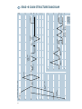
LEVEL-SETTING PROCEDURE
There isn’t too much to setting levels. No
rocket science here (well… maybe a bit).
Here’s what you need to do:
Hyper-Quick-Turbo Method
1.Set the TRIM
controls
at minimum (fully counterclockwise).
2. Set the METERING: INPUT SECTION
switch to PFL mode
so your Fader
settings won’t affect your input meter
readings.
3. Set the METERING: OUTPUT SECTION
switch to AFL mode
so that the Meters
reflect the actual output levels.
4. Set all of the Faders to their “U” markings.
5. Ask the musicians to start playing.
6. Set a rough mix, using the TRIM controls.
The goal is to get Meter readings at or
around 0dB for all of the inputs.
7. Once you’ve adjusted the input levels, use
the Channel Faders to set the Channel
levels, and leave the TRIM controls alone.
8. If the overall level gets too loud, bring the
overall LEFT and RIGHT level down a bit,
10dB at the most. You may need to reduce
the TRIM settings further.
Alternate Method
This method results in the faders being in a
straight line across the board.
1. Set the METERING: INPUT SECTION
switch to PFL mode
so your Fader
settings won’t affect your input meter
readings.
2. Set the METERING: OUTPUT SECTION
switch to AFL mode
so that the Meters
reflect the actual output levels.
3. While the musicians are playing, watch
each Channel Meter and adjust the TRIM
control so that level is near 0dB as read
on the Channel’s Meter.
4. After setting the Channel EQ, you will
probably want to readjust the TRIM control
slightly to bring the Meter back to near the
0dB reading.
5. As the mix comes together, readjust the TRIM
control down so that the Channel Fader can
be set at its “U” (unity gain) setting.
6. You can also SOLO the Channel and
monitor its level via the LEFT, RIGHT, and
CENTER Meters in the output section.
Other Nuggets of Wisdom
Before plugging or unplugging a cord from a
Channel or a MAIN AUX RETURN (A1–A4), be
sure to engage the MUTE switch first.
If you shut down your equipment, turn off
your amplifiers first. When powering up, turn
on your amplifiers last.
Save the shipping boxes! We’re sure that
you can find an empty airport hanger or boat
moorage to store them. You may need them
someday, and you don’t want to have to pay for
them again.
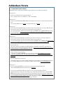
Please write your serial numbers here for
future reference (i.e., insurance claims,
tech support, return authorization, etc.):
Console
Power Supply
Purchased at:
Date of purchase:
Part No. 820-052-00 Rev. B 6/97
©1997 Mackie Designs Inc., All Rights Reserved. Printed in the U.S.A.
3
INTRODUCTION
Thank you! You have voted with your wallet for the folks in Woodinville who specialize
in mixing. The SR40•8 and SR56•8 Large
Format Sound Reinforcement Consoles are
designed to fulfill the mixing needs of almost
any type of sound reinforcement application,
and it boasts a wealth of features for which
you’d expect to pay a lot more. Although you
may be familiar with these features, your investment will pay for itself much faster if you
take the time to read this manual. (If reading
manuals is not your style, please do it anyway,
just don’t tell anyone you did.)
HOW TO USE THIS MANUAL
In order to simplify things throughout the
rest of the manual we refer to the console as
the SR40•8, but rest assured that all the features described herein are identical to the
features you will find on the SR56•8.
Feature Descriptions: Mind-boggling Details
Each and every knob, button and connector
on the SR40•8 is explained in depth here including the points before and after in the
signal chain. This is to give you a better sense
of exactly where in the signal path a particular
control or connector is located. Each feature is
described in order of where it is physically located on the console’s top or rear panel. These
descriptions are divided into three sections,
just as your mixer is organized into three distinct zones:
1. PATCH PANEL: The zillion jacks on the
back “pod.”
2. CHANNEL: The 40 Channel strips on the
left and right. The Main Aux Return strips
contain many similiar features.
3. OUTPUT SECTION: The output section in
the center.
Overview: The SR40•8 In A Nutshell
If you’re new to mixing, or unfamiliar with
some of the features on the SR40•8, check out
the Overview section and Hookup Diagrams.
They provide a quick summary of the basic
functions of your SR40•8.
PATCH PANEL
CHANNELS
CHANNELS
MAIN
“A”
AUX
RETS.
OUTPUT
4
Special Icons
Throughout these chapters you’ll find illustrations, with each feature numbered. If you’re
curious about a feature, simply locate it on the
appropriate illustration, note the number attached to it, and find that number in the
nearby paragraphs.
This icon marks information that is critically important or unique to the SR40•8. For
your own good, read these sections and
remember them.
This icon will lead you to in-depth explanations
of features and practical tips. While not mandatory,
they’ll have some valuable information.
The Glossary: A Haven Of Non-techiness For The
Neophyte
Just in case you’re new to the audio world,
we’ve included a fairly comprehensive dictionary of pro audio terms. If terms like
“clipping,” “noise floor,” or “unbalanced” leave
you blank, flip to the glossary at the back of
this manual for a quick explanation.
A Plug For The Connectors Section
Also at the back of this manual is a section
on connectors: XLR, TRS and RCA connectors,
balanced connectors, unbalanced connectors,
special hybrid connectors. If you plan on wiring your own cables, please visit this section
before you start.
Arcane Mysteries Illuminated
Last but not least, we’ve included an appendix titled “Balanced Lines, Phantom Powering,
Grounding and Other Arcane Mysteries.” This
section discusses some of the down ’n’ dirty
practical realities of microphones, fixed installations, grounding and balanced versus
unbalanced lines. It’s a gold mine for the neophyte, and even the seasoned pro might learn
a thing or two.
5
CONTENTS
READ THIS PAGE!!! .................................................... 3
LEVEL-SETTING PROCEDURE ......................... 3
HYPER-QUICK-TURBO METHOD .................... 3
ALTERNATE METHOD .................................... 3
OTHER NUGGETS OF WISDOM ...................... 3
INTRODUCTION ......................................................... 4
SR40•8 HOOKUP EXAMPLES .............................. 8
OVERVIEW: THE SR40•8 IN A NUTSHELL ................. 10
MIXING ...................................................... 10
MATRIX ..................................................... 10
STAGE MONITORS & EFFECTS ...................... 10
MONITORING, SOLO & METERING .............. 11
TALKBACK & INTERCOM ............................. 11
ULTRA MUTE™ ........................................... 11
SWITCH POSITIONS .................................... 11
PATCH PANEL ................................................... 12
E-Z INTERFACE............................................ 12
MIC INPUT .................................................. 12
LINE IN ....................................................... 13
INSERT SEND AND RETURN ......................... 13
DIRECT OUT ................................................ 13
MAIN AUX RETURNS (A1–A4) .................... 14
“B” AUX RETURNS ..................................... 14
TAPE INPUT ................................................ 15
TAPE A OUTPUT .......................................... 15
TAPE B OUTPUT .......................................... 15
AUX SEND .................................................. 15
MAIN OUTPUTS .......................................... 16
MAIN INSERTS ............................................ 16
SUB OUTPUTS ............................................. 16
SUB INSERTS .............................................. 17
HEADPHONES ....................................... 17
L-INSERT, R-INSERT (HEADPHONES) ........... 17
MONITOR ................................................... 18
TALKBACK .................................................. 18
TALKBACK MIC INPUT ........................... 18
INTERCOM .................................................. 19
MATRIX OUTPUTS ...................................... 19
MATRIX INPUTS ......................................... 19
DC POWER IN ............................................. 19
MIDI IN/OUT .............................................. 19
DATA .......................................................... 19
CHANNEL .......................................................... 20
“U” LIKE UNITY GAIN ................................. 20
CHANNEL INPUT CONTROLS ....................... 20
+48 PH (PHANTOM POWER) ................ 20
TRIM .................................................... 20
Ø (POLARITY REVERSAL)...................... 20
6
EQ .............................................................. 21
HI 12K ................................................. 21
HI MID AND
FREQ .......................... 21
LOW MID AND
FREQ ...................... 22
LOW 80HZ ........................................... 22
EQ IN ................................................... 22
HPF AND
FREQ ............................... 22
CHANNEL OUTPUT CONTROLS .................... 23
MUTE ................................................... 23
FADER .................................................. 24
A CLEAN FADE ...................................... 24
PAN ..................................................... 24
CONSTANT LOUDNESS.......................... 24
1-2, 3-4, 5-6, 7-8, L-R (ASSIGN) .......... 24
CENTER (ASSIGN) ................................. 25
SOLO ................................................... 25
METER ................................................. 26
AUX SEND ............................................ 26
PRE switch (AUX 1–4) .......................... 26
PRE FDR/POST EQ (AUX SENDS 5–8) ... 27
MAIN AUX RETURNS (A1–A4) .................... 27
TRIM .................................................... 27
HPF ...................................................... 27
EQ ........................................................ 27
PAN ..................................................... 28
1-2, 3-4, 5-6, 7-8, L-R (ASSIGN) .......... 28
CENTER (ASSIGN) ................................. 28
SOLO ................................................... 28
METER ................................................. 28
AUX SEND ............................................ 28
OUTPUT SECTION .............................................. 29
LEFT/RIGHT/CENTER MIXES ....................... 29
LEFT FADER .......................................... 29
RIGHT FADER ....................................... 29
FADER LINK .......................................... 29
CENTER FADER ..................................... 30
SOLO ................................................... 30
SUBS (SUB 1-8 MIXES) ............................... 31
FADER .................................................. 31
MUTE ................................................... 31
PAN ..................................................... 31
L-R (ASSIGN) ....................................... 31
CENTER (ASSIGN) ................................. 31
SOLO ................................................... 32
AIR ...................................................... 32
METERS................................................ 32
“B” AUX RETURNS and
TAPE RETURNS ... 33
LEVEL ................................................... 33
MUTE ................................................... 33
SOLO ................................................... 33
AUX SEND MASTERS ................................... 34
FLIP ..................................................... 34
LEVEL ................................................... 34
MUTE ................................................... 35
SOLO ................................................... 35
SOLO MASTER CONTROLS........................... 35
INPUTS PFL/AFL .................................. 35
OUTPUTS PFL/AFL ............................... 35
SOLO LEVEL .......................................... 36
RUDE SOLO LIGHT ................................ 36
PHONES LEVEL ............................................ 36
MONITOR ................................................... 37
LINE OUT (LEVEL) ................................. 37
MUTE ................................................... 37
LEFT/RIGHT/CENTER METERS .................... 37
METERING ........................................................ 37
INPUT SECTION PFL/AFL ...................... 37
OUTPUT SECTION PFL/AFL ................... 38
DIMMER ........................................................... 38
LAMP ................................................... 38
METER ................................................. 38
POWER SUPPLY STATUS ............................. 38
TALKBACK SECTION .................................... 38
TALKBACK ............................................ 38
TALKBACK LEVEL .................................. 38
ASSIGN ................................................ 39
OSCILLATOR SECTION ................................. 39
400HZ/PINK NOISE............................. 39
LEVEL ................................................... 39
ON ....................................................... 40
COMMUNICATIONS .................................... 40
INTERCOM ........................................... 40
RECEIVE LEVEL ..................................... 40
IGNORE ............................................... 40
CALL .................................................... 40
MATRIX ..................................................... 41
INPUT LEVEL ........................................ 41
MUTE ................................................... 41
MASTER LEVEL ..................................... 41
SOLO ................................................... 41
ULTRA MUTE™ AUTOMATION ..................... 42
TYPICAL APPLICATIONS ............................... 42
IMPORTANT TIDBITS AND TITTLES ............... 43
OPERATION .................................................. 44
GROUP MODE ........................................ 44
NUMERIC DISPLAY .......................... 44
SNAPSHOT MODE .................................. 46
ULTRA MUTE SUMMARY ....................... 48
MODE .............................................. 48
ARROW UP/DOWN BUTTONS ....... 48
SYSTEM BYPASS ............................ 48
MUTE PREVIEW ............................. 48
STORE ........................................... 49
CLEAR ............................................ 49
DO IT ............................................. 49
NUMBER BUTTONS (0-9) ................ 49
MIDI IMPLEMENTATION ...................................... 50
MIDI SYSEX NUMBERS .......................... 51
MIDI IMPLEMENTATION SUMMARY ..... 52
MIDI IMPLEMENTATION CHART...... 53
TABLE OF MIDI NOTE MESSAGES .... 54
SR40•8 BLOCK DIAGRAM ................................. 56
SR40•8 GAIN STRUCTURE DIAGRAM ................ 58
SPECIFICATIONS ............................................... 60
APPENDIX A: Service Info ........................................ 62
TROUBLESHOOTING .......................................... 62
APPENDIX B: Glossary ............................................. 63
APPENDIX C: Connections ........................................ 72
APPENDIX D: Balanced Lines, Phantom Powering,
Grounding, and Other Arcane Mysteries ............. 75
APPENDIX E: Track Sheets ....................................... 80
7
SR40•8 HOOKUP EXAMPLES
Stage
Monitor
Power Amp
mono mode
Stage
Monitor
Power Amp
mono mode
Stage
Monitor
Stage
Monitor
Reverb #1
Power Amp
mono mode
Power Amp
mono mode
Reverb #2
Delay
Harmonizer
PFL
Monitor
Power Amp
mono mode
Stereo EQ
and Compressor
SUB INSERTS
MAIN INSERTS
(BAL/UNBAL)
(BAL/UNBAL)
SEND
1
RETURN
SEND
5
RETURN
AUX SEND
MONITOR
L
(BAL/UNBAL)
5
1
(MONO)
L
1
2
RETURN
SEND
6
RETURN
RIGHT SEND
R
RIGHT RETURN
6
2
(MONO)
L
2
24
23
(MONO)
L
A1
R
DIRECT OUT
DIRECT OUT
(MONO)
L
A2
R
INSERT SEND
INSERT SEND
(MONO)
L
A3
R
INSERT RETURN
INSERT RETURN
(MONO)
L
A4
R
LINE IN
LINE IN
MIC 24
MIC 24
MAIN AUX RETURNS
TAPE
"B" AUX RETURNS
(BAL/UNBAL)
(BAL/UNBAL)
LEFT RETURN
LEFT SEND
R
TAPE A
L
SEND
Reverb
DAT Recorder
Vocal Maximizer
L
R
R
R
TAPE
INPUT
TAPE
OUTPUT
SOURCE =
MASTER L-R
SEND
SEND
3
4
RETURN
RETURN
SEND
SEND
7
8
RETURN
RETURN
CNTR SEND
L-INSERT
CNTR RETURN
R-INSERT
TALKBACK
HEADPHONES
7
3
8
4
(MONO)
(MONO)
L
L
3
4
R
TAPE B
L
L
R
R
R
TAPE
INPUT
TAPE
OUTPUT
SOURCE =
MATRIX C&D
INTERCOM
TALK BACK MIC
PHANTOM POWERED
MAIN OUTPUTS
LEFT
RIGHT
Power Amp
stereo mode
MATRIX OUTPUTS
CENTER
MATRIX A
Power Amp
mono mode
Power Amp
mono mode
MATRIX B
MATRIX C
MATRIX INPUTS
MATRIX D
A
B
C
D
Power Amp
mono mode
Click Track
for Drummer
Drummer
Monitor
Bar P.A.
Speaker
Right P.A.
Speaker
Left P.A.
Speaker
Balcony P.A.
Speaker
SR40•8/SR56•8 BAND IN A CLUB
8
Stage
Monitor
Reverb #1
Stage
Monitor
Stage
Monitor Power Amp
mono mode
Power Amp
mono mode
Power Amp
mono mode
Reverb #2
Stage
Monitor
Delay
Harmonizer
Power Amp
mono mode
Cassette
Recorder
Vocal Compressor
DAT Recorder
SUB INSERTS
MAIN INSERTS
(BAL/UNBAL)
(BAL/UNBAL)
SEND
1
RETURN
SEND
5
RETURN
AUX SEND
MONITOR
L
(BAL/UNBAL)
5
1
(MONO)
L
1
R
2
RETURN
SEND
6
RETURN
RIGHT SEND
R
RIGHT RETURN
6
2
(MONO)
L
2
23
L
A1
R
DIRECT OUT
DIRECT OUT
(MONO)
L
A2
R
INSERT SEND
INSERT SEND
(MONO)
L
A3
R
INSERT RETURN
INSERT RETURN
(MONO)
L
A4
R
LINE IN
LINE IN
MIC 24
MIC 24
MAIN AUX RETURNS
TAPE A
L
SEND
24
(MONO)
TAPE
"B" AUX RETURNS
(BAL/UNBAL)
(BAL/UNBAL)
LEFT RETURN
LEFT SEND
L
R
R
R
TAPE
INPUT
TAPE
OUTPUT
SOURCE =
MASTER L-R
SEND
SEND
3
4
RETURN
RETURN
SEND
SEND
7
8
RETURN
RETURN
CNTR SEND
L-INSERT
CNTR RETURN
R-INSERT
TALKBACK
HEADPHONES
7
3
8
4
(MONO)
(MONO)
L
3
L
4
R
TAPE B
L
L
R
R
R
TAPE
INPUT
TAPE
OUTPUT
SOURCE =
MATRIX C&D
TALK BACK MIC
PHANTOM POWERED
INTERCOM
MAIN OUTPUTS
LEFT
RIGHT
MATRIX OUTPUTS
CENTER
Power Amp
mono mode
MATRIX A
MATRIX B
Power Amp
mono mode
MATRIX C
MATRIX INPUTS
MATRIX D
Right P.A.
Speaker
B
C
D
Audio Snake
Power Amp
mono mode
Power Amp
mono mode
Power Amp
mono mode
A
Nursery Zone
Direct
boxes
Keyboard or other line level input
Nursery Zone
Left P.A.
Speaker
Center Cluster
DAT Recorder
Assistive Listening
Infrared Transmitter
SR40•8/SR56•8 HOUSE OF WORSHIP
9
OVERVIEW: THE SR40•8 IN A NUTSHELL
This section provides a quick summary of the
SR40•8’s major features. It is not intended to be
a dissertation on how to use a mixer, especially
the SR40•8, where the possibilities are endless.
Just the same, it’s a good place to get started.
MIXING
Channel controls manipulate mic/line
signals in this order: phantom power, trim, polarity, low cut filter, insert, EQ, mute, fader,
pan, and assignment switches. These signals
are then assigned to the left, right and/or center mix, or to one of the eight subs.
The main mix (left, right and center) typically feeds the main sound system. The left/
right mix can be controlled by individual faders or switched to share one fader. Subs 1-8
can be assigned to the left/right or center mix,
enabling them to be used as master faders for
submixes of channels. Alternatively, the subs
can be used for secondary speaker systems.
More output routing options involve the
matrix, discussed below.
MATRIX
The SR40•8 has 11 primary mix buses: left,
right, center, and 8 subs. Via the channel’s assignment switching, signals can be distributed
among these buses. If a situation demands a
unique destination for each mix, the dedicated
outputs for each of these mixes will suffice.
More likely, a situation will demand that
these 11 mixes be recombined in some way, to
feed off-site systems, delay towers, assistive listening systems, or special mixes for recording
or broadcast. Enter the Matrix.
The matrix is simply four separate 12 x 1
mixers. Its inputs include: left, right, center,
subs 1-8 and an external input at the patch
panel. Each matrix strip has a level control for
each of the eleven internal inputs as well as
master level, solo and mute controls.
10
STAGE MONITORS & EFFECTS
Every channel, as well as each of the four
main aux returns (A1–A4), has eight aux send
controls. Per channel, aux sends 1–4 can be
switched to be post-fader (for effects sends) or
pre-EQ/pre-fader (for stage monitors). Aux
sends 5–8 have a similar switch, post-fader (for
effects sends) or post-EQ/pre-fader (for stage
monitors with EQ).
In the output section, aux sends can be
routed in one of two ways. Normally, these aux
mixes are controlled by the rotary master level
control and mute switch, and then sent to TRS
output jacks. This method is fine for effects
sends or small applications. Larger installations may demand more flexibility for the stage
mixes. Enter the flip switch.
Each aux send master has a flip switch.
This removes an aux mix from its dedicated
mute switch and level control, and diverts it
to the like-numbered sub routing. This way,
an aux send designated for stage cueing will
have its own dedicated 100mm fader, “Air”
EQ, insert, and balanced XLR output. Meanwhile, a flipped aux send also diverts the sub
signal to the original aux send master controls and TRS output, ensuring that sub
assignments can still be used.
When used for effects, aux sends are
patched into the inputs of parallel effects devices, like reverb and delay units. The outputs
of these devices are the origin of aux return
signals. Aux return signals, or any stereo linelevel signals, can be injected into either the
main aux returns or the “B” aux returns (or
into pairs of channels). The main aux returns
provide most of the controls present in the
channels: trim, high-pass filter, EQ, mute, pan,
and assign. “B” aux returns B1, B2, and B3 are
dedicated to the left/right mix and offer only
rotary level and mute switch controls. (Aux
return B4 is dedicated to the center mix.)
Additionally, there are two stereo line-level
RCA tape returns, dedicated to the left/right
mix, with level control and mute switch.
MONITORING, SOLO, & METERING
Usually an engineer listens to the left/right
mix (with the center mix blended in), just as
the audience is hearing it. Signals available for
monitoring by the engineer are available via either of the high-powered headphone outputs,
with level control, or a line-level monitor (control room) output, also with level control.
There is a stereo insert dedicated to the
phones mix, to allow a delay device to synchronize the distance delay present in large halls.
To audition individual signals or groups of
signals, there are solo switches on every channel, main aux return, aux send master, matrix
A–D, tape return, and sub 1–8, as well as the
left/right/center faders. The engineer behind an
SR40•8 can listen to any signal, individually or
in groups, without disturbing the content of any
of the console’s primary outputs. Input signals
(channels, main aux returns, “B” aux returns,
tape A, and tape B) can be globally switched
PFL (pre-fader-listen) or AFL (after-fader-listen, stereo-in-place). Output signals (main/left/
right, subs 1–8, aux send masters, and matrix
A–D) have a similar switch.
There are 59 twelve-segment LED-ladder
meter displays on the SR40•8, one for each
channel and sub, two for each stereo main aux
return, and one each for the left/right/center
main mixes. Input and output meters can each
be globally switched PFL or AFL. During solo,
described earlier, the left/right/center meters
automatically display the solo levels: AFL on
the left/right meters and PFL on the center.
TALKBACK & INTERCOM
The SR40•8’s extensive talkback section allows the engineer to speak into several outputs
via a master talkback switch, with assignment
switches for aux 1–4, aux 5–8, L/R mix, an
external talkback output, and one switch for
each matrix (A–D). Talkback microphones are
patched into either of the two phantom powered XLR inputs and regulated by a level
control. Additionally, the talkback signal may
be replaced by a 400Hz sine wave for checking
levels, or pink noise for quickly checking
frequency response.
The Clear-Com® Intercom System is already
standard equipment in most large facilities. It
allows all crew members to share a “party line,”
so they may communicate at will, without
having to toggle between send and receive.
The Mackie SR40•8 takes that a step farther
by allowing the engineer to join in at his/her
discretion using the talkback microphone and
phones outputs: No separate intercom headset
is required for the engineer.
ULTRA MUTE™
Almost every signal path in the SR40•8
has an electronically-controlled mute switch,
including the channels, main aux return, subgroups, aux sends, and matrices. These mutes
may be activated in four ways: By pressing the
local mute switch included for each path, by
assigning paths to a mute group, by assigning
paths to a mute snapshot, or by external MIDI
and RS232 commands. Using just the local
switches and mute groups, an engineer can
quickly mute or un-mute large groups of signal
paths. Using an external sequencer to generate
MIDI muting commands, complicated muting
moves can be made automatically, with no
user intervention.
When a channel or main aux return is
muted, the entire channel is muted, including
the assign outputs, pre- and post-fader aux
sends, and direct out. The insert send remains
active, as do the channel’s PFL meters and
PFL solo outputs.
SWITCH POSITIONS
You may have noticed the white lines
printed just above most of the push-button
switches on your SR40•8. We’ve put them there
to make it easier for you to see if the switch is
engaged (down). Here’s how they work:
Assuming you are sitting in front of the console, when a switch is disengaged (up), its
button hides the white line from your field of
vision. When you engage the switch, the line
suddenly appears. Although it may not seem
obvious at first, you’ll soon find that the indicator line really helps you determine switch
positions at a glance. Clever, ain’t it?
11
PATCH PANEL
At the risk of stating the obvious, this is
where you plug everything in: microphones,
instruments, effects, headphones, and the ultimate destination for your sound: PA system,
tape recorder and the like.
E-Z INTERFACE
Concerned about levels,
balancing, impedances,
polarity, or other interface
goblins? Don’t be. On your
SR40•8, you can patch anything almost anywhere, with nary a care. Here’s why:
• Every input and output is balanced (except
single-jack inserts, phones and RCA jacks),
using close-tolerance components to
ensure noise-free performance.
• Every input and output will also accept
unbalanced lines (except floating-ring
cables into XLR inputs — just tie the
cable’s ring to the shield first).
• Every input is designed to accept virtually
any output impedance.
• The XLR outputs can deliver 28dBu into a
600 ohm load.
• All the other outputs can deliver 22dBu
into a 600 ohm load.
• All the outputs are polarity-correct with
the inputs.
All we ask is that you perform the Levelevery time you patch in
Setting Procedure
a new sound source. So stop worrying, and
start mixing!
MIC INPUT
Point Before: Balanced microphone-level
cable with male XLR connector (pin 2 = hot,
pin 3 = cold, pin 1 = shield).
.
Point After: Channel
The female XLR input can accept almost
any type of microphone — dynamic, condenser, ribbon or tube condenser. +48 PH
(phantom power)
is switchable per Channel. Radio frequency interference (RFI) is
eliminated by means of close-tolerance balanced circuitry, input filtering and the
SR40•8’s steel chassis. Mic-level signals can be
boosted by as much as 60dB.
Do not use this input simultaneously with
down
its associated LINE IN . Turn TRIM
before inserting or reand engage MUTE
moving mic cables. Do not insert unbalanced
single-ended cables (signal on pin 2, pin 3
open) unless pin 3 is first tied to ground (pin
is switched off.
1), and the +48 PH
SUB OUTPUTS
25
SUB INSERTS
(BAL/UNBAL)
DIRECT OUT
SUB
SUB
SUB
SUB
1
2
3
4
INSERT SEND
INSERT RETURN
SUB
SUB
SUB
SUB
5
6
7
8
LINE IN
DC POWER IN
MIDI IN
MIDI OUT
DATA
12
1
RETURN
SEND
5
RETURN
SEND
2
RETURN
SEND
6
RETURN
SEND
3
RETURN
SEND
7
RETURN
SEND
4
RETURN
SEND
8
RETURN
TALK BACK MIC
PHANTOM POWERED
(MACKIE 400-WATT POWER SUPPLY !)
MIC 25
SEND
INTERCOM
LEFT
LINE IN
Point Before: Balanced or unbalanced mic- or
line-level cable with 1⁄4" TRS or TS connector,
(tip = hot, ring = cold, sleeve = shield).
Point After: Channel .
This input is similar to the MIC
input,
but without phantom power. Both signals mix
together at the mic preamp. Mic-level signals
can be accommodated here with up to 40dB of
gain. The LINE IN is 20dB less sensitive than
the MIC input.
Do not use this input simultaneously with its
input. Turn TRIM
down
associated MIC
before inserting or reand engage MUTE
moving line cables. Do not use open-ended TRS
cables (signal on tip, ring open) unless the ring
is first tied to ground (sleeve). It won’t hurt
anything, it will just work better if you ground
the sleeve. Although you can connect a microphone to this input, there will be less noise
input jack.
when connected to the MIC
INSERT SEND AND RETURN
Point Before: Channel mic/line preamp, TRIM
, 0/ (Polarity Reversal) ,HPF .
Point After: EQ .
Both the INSERT SEND and INSERT
RETURN jacks are balanced, and can also
accommodate unbalanced TS cables. Signal
feeding the INSERT SEND jack is also sent to
MAIN INSERTS
(BAL/UNBAL)
LEFT RETURN
LEFT SEND
RIGHT SEND
RIGHT RETURN
AUX SEND
MONITOR
L
R
1
Point Before: Channel signal, EQ , Channel Fader , MUTE .
Point After: Balanced or unbalanced cable
with 1⁄4" TRS or TS connector.
The DIRECT OUT’s signal is the same as the
output of the Channel, except that the PAN
control has no effect.
These jacks can be used to feed multitrack
recorder inputs, as a one-channel effects send,
as a secondary sound source’s trigger command, or for any other purpose that requires
the post-Fader signal of an individual Channel.
Using this jack does not interrupt the
Channel’s signal path to the output section.
6
(MONO)
(MONO)
L
L
1
2
R
TAPE A
L
L
R
R
R
TAPE
INPUT
24
MAIN AUX RETURNS
TAPE
(BAL/UNBAL)
5
2
DIRECT OUT
"B" AUX RETURNS
(BAL/UNBAL)
(BAL/UNBAL)
the INSERT RETURN jack’s normalling pins.
With nothing plugged into the INSERT
RETURN jack, the (dry) send signal will be
passed along to the rest of the channel path
(this is called half-normalled).
To insert a serial effects device, simply patch
from the INSERT SEND jack to the effect’s input, and from the effect’s output to the INSERT
RETURN jack, using either balanced TRS or
unbalanced TS cables.
Since using the INSERT SEND jack by itself does not interrupt the channel’s signal
path, it may also be used as a pre-EQ/preFader direct output, in addition to the
post-Fader DIRECT OUT .
(MONO)
L
A1
R
DIRECT OUT
(MONO)
L
A2
R
INSERT SEND
(MONO)
L
A3
R
INSERT RETURN
(MONO)
L
A4
R
LINE IN
TAPE
OUTPUT
SOURCE =
MASTER L-R
CNTR SEND
L-INSERT
CNTR RETURN
R-INSERT
TALKBACK
HEADPHONES
3
7
4
8
(MONO)
(MONO)
L
L
3
4
R
TAPE B
L
L
R
R
R
TAPE
INPUT
TAPE
OUTPUT
SOURCE =
MATRIX C&D
MAIN OUTPUTS
RIGHT
MATRIX OUTPUTS
CENTER
MATRIX A
MATRIX B
MATRIX C
MATRIX INPUTS
MATRIX D
A
B
C
D
13
MIC 24
MAIN AUX RETURNS (A1–A4)
“B” AUX RETURNS
Point Before: Balanced or unbalanced linelevel cable with 1⁄4" TRS or TS connector,
(tip = hot, ring = cold, sleeve = shield).
Point After: MAIN AUX RETURNS (A1–A4) .
The left jack’s signal is normalled to the right
jack — a mono signal, patched into the left jack
only, appears on the left and right sides.
Since the MAIN AUX RETURNS (A1–A4) are
actually stereo channels with full routing and
EQ, patch in the outputs of your essential
effects devices (or any line-level signals) here.
These signals can be sent to any mix, including
the AUX SEND MASTERS , making them
ideal for sending effects to the stage monitors.
Similarly, essential mono effects outputs (one
cable) should be patched into a mono Channel.
Point Before: Balanced or unbalanced linelevel cable with 1⁄4" TRS or TS connector,
(tip = hot, ring = cold, sleeve = shield).
Point After: “B” AUX RETURNS .
The left jack’s signal is normalled to the right
jack — a mono signal, patched into the left jack
only, will appear on the left and right sides.
Since AUX RETURNS B1, B2 and B3 can be
assigned only to the LEFT/RIGHT mix, and B4
only to the CENTER mix, patch the outputs of effects devices (or any line-level signals) that need
to go only to these destinations. If you need full
routing but you’ve already used all four of the
MAIN AUX RETURNS (A1–A4), you can also
patch into two Channels, panning one left and
the other right.
SUB OUTPUTS
25
SUB INSERTS
(BAL/UNBAL)
DIRECT OUT
SUB
SUB
SUB
SUB
1
2
3
4
INSERT SEND
INSERT RETURN
SUB
SUB
SUB
SUB
5
6
7
8
LINE IN
DC POWER IN
MIDI IN
MIDI OUT
DATA
14
1
RETURN
SEND
5
RETURN
SEND
2
RETURN
SEND
6
RETURN
SEND
3
RETURN
SEND
7
RETURN
SEND
4
RETURN
SEND
8
RETURN
TALK BACK MIC
PHANTOM POWERED
(MACKIE 400-WATT POWER SUPPLY !)
MIC 25
SEND
INTERCOM
LEFT
TAPE INPUT
TAPE B OUTPUT
Point Before: Unbalanced line-level cable with
RCA connector.
Point After: TAPE RETURNS .
RCA jacks, bless their little hearts, have no
normalling — if you need a mono signal to appear on both sides, that will require a Y-splitter
so that both jacks can be patched.
This is a good place to patch in a tape
deck or CD player intended for music between sets. TAPE RETURNS are dedicated to
the LEFT and RIGHT mix .
TAPE A OUTPUT
Point Before: MAIN OUTPUTS .
Point After: Unbalanced line-level cable with
RCA connector.
These jacks have a 3kΩ output impedance,
enabling you to combine the left and right outputs (using a Y-cord adapter), thereby creating
a mono signal. Do not attempt this on any of
the SR40•8’s TRS or XLR outputs.
Patch these outputs to the inputs of a
2-track recording device and you’ll record exactly the same signals present at the left and
right MAIN OUTPUTS .
MAIN INSERTS
(BAL/UNBAL)
LEFT RETURN
LEFT SEND
RIGHT SEND
RIGHT RETURN
AUX SEND
MONITOR
L
R
1
Point Before: AUX SEND MASTERS .
Point After: Balanced or unbalanced cable
with 1⁄4" TRS or TS connector.
Patch these outputs to the inputs of your
effects devices or stage monitor amps. Rememis engaged, these outputs
ber that if FLIP
deliver the like-numbered SUB OUTPUTS
instead of AUX SEND outputs.
6
(MONO)
(MONO)
L
L
1
2
R
TAPE A
L
L
R
R
R
TAPE
INPUT
24
MAIN AUX RETURNS
TAPE
(BAL/UNBAL)
5
2
AUX SEND
"B" AUX RETURNS
(BAL/UNBAL)
(BAL/UNBAL)
Point Before: MATRIX OUTPUTS , left from
MATRIX C output, right from MATRIX D output.
Point After: Unbalanced line-level cable with
RCA connector.
These jacks have a 3kΩ output impedance,
enabling you to combine the left and right outputs (using a Y-cord adapter), thereby creating
a mono signal. Do not attempt this on any of
the SR40•8’s TRS or XLR outputs.
Patch these outputs to the inputs of a
2-track recording device and you’ll record exactly the same signals present at the MATRIX
C and D XLR jacks.
OUTPUTS’
(MONO)
L
A1
R
DIRECT OUT
(MONO)
L
A2
R
INSERT SEND
(MONO)
L
A3
R
INSERT RETURN
(MONO)
L
A4
R
LINE IN
TAPE
OUTPUT
SOURCE =
MASTER L-R
CNTR SEND
L-INSERT
CNTR RETURN
R-INSERT
TALKBACK
HEADPHONES
3
7
4
8
(MONO)
(MONO)
L
L
3
4
R
TAPE B
L
L
R
R
R
TAPE
INPUT
TAPE
OUTPUT
SOURCE =
MATRIX C&D
MAIN OUTPUTS
RIGHT
MATRIX OUTPUTS
CENTER
MATRIX A
MATRIX B
MATRIX C
MATRIX INPUTS
MATRIX D
A
B
C
D
15
MIC 24
MAIN OUTPUTS
Point Before: LEFT/RIGHT/CENTER mixes ,
MAIN INSERTS ,LEFT/RIGHT/CENTER
Faders
.
Point After: Balanced or unbalanced cable
with female XLR connector (pin 2 = hot, pin 3
= cold, pin 1 = shield).
Unless you’ve created an elaborate main
mix using the MATRIX , patch these outputs
to your primary sound system’s amplifier inputs. Be aware that if you have no Channels
or MAIN AUX RETURNS (A1–A4)
assigned to the CENTER mix, patching the
CENTER output jack is unnecessary.
MAIN INSERTS
Point Before: LEFT/RIGHT/CENTER mix .
Point After: LEFT/RIGHT/CENTER Faders
.
Both the SEND and RETURN jacks are balanced, but can accommodate unbalanced TS
cables. Signal feeding the SEND jack is also
sent to the RETURN jack’s normalling pins.
With nothing plugged into the RETURN jack,
the (dry) SEND signal gets passed along to the
rest of the mix output’s path.
To insert a serial processor (such as a
graphic equalizer or compressor/limiter), simply
patch from the SEND jack to the effect’s input,
and from the effect’s output to the RETURN
jack, using either balanced TRS or unbalanced
TS cables. Since using the SEND jack by itself
does not interrupt the mix signal path, it may
also be used as a pre-Fader direct output.
SUB OUTPUTS
Point Before: SUBS (SUB 1-8 mixes) , SUB
INSERTS , Subgroup Fader .
Point After: Balanced or unbalanced cable
with female XLR connector (pin 2 = hot, pin 3
= cold, pin 1 = shield).
If necessary, patch these outputs to the
amplifier inputs of secondary speaker systems,
unless you’ve chosen to use the MATRIX
for this task. The Subgroups are
OUTPUTS
also essential for recording to multitrack.
In the event that you have engaged any FLIP
switches, the signals at these outputs will
not be the Subgroup signals — they will be the
like-numbered AUX SEND ouputs. (For instance, if the FLIP switch on AUX SEND
MASTER 1 is engaged, AUX SEND 1’s output
will appear at Subgroup 1’s output jack, and
vice versa.)
SUB OUTPUTS
25
SUB INSERTS
(BAL/UNBAL)
DIRECT OUT
SUB
SUB
SUB
SUB
1
2
3
4
INSERT SEND
INSERT RETURN
SUB
SUB
SUB
SUB
5
6
7
8
LINE IN
DC POWER IN
MIDI IN
MIDI OUT
DATA
16
1
RETURN
SEND
5
RETURN
SEND
2
RETURN
SEND
6
RETURN
SEND
3
RETURN
SEND
7
RETURN
SEND
4
RETURN
SEND
8
RETURN
TALK BACK MIC
PHANTOM POWERED
(MACKIE 400-WATT POWER SUPPLY !)
MIC 25
SEND
INTERCOM
LEFT
SUB INSERTS
WARNING: The
SR40•8’s stereo phones
jack will drive any standard headphone to very
loud levels. When we say
the headphone amp is loud, we’re not kidding. It can cause permanent ear damage.
Even intermediate levels may be painfully
loud with some earphones. BE CAREFUL!
all the
Always turn the PHONES level
way down before connecting headphones. Keep
it down until you’ve put the phones on. Then
turn it up slowly. Why? “Engineers who fry their
ears find themselves with short careers.”
The SR40•8’s headphone amplifiers will
drive headphones of any impedance, but for
best results (loudest volume), use 60-ohm
headphones.
Point Before: SUB 1–8 mixes , AIR ,
FLIP .
Point After: SUBS 1–8 Faders .
Both the SEND and
RETURN jacks are balanced,
but can accommodate unbalanced TS cables. Signal
feeding the SEND jack is also
sent to the RETURN jack’s normalling pins.
With nothing plugged into the RETURN jack,
the (dry) SEND signal gets passed along to the
rest of the mix output’s path. (The jacks are
half-normalled.)
To insert a serial processor (such as a
graphic equalizer or compressor/limiter), simply
patch from the SEND jack to the effect’s input,
and from the effect’s output to the RETURN
jack, using either balanced TRS or unbalanced
TS cables. Since using the SEND jack by itself
does not interrupt the mix signal path, it may
also be used as a pre-Fader direct output.
Point Before: PHONES level .
Point After: HEADPHONES
and
MONITOR outputs .
Per side, these unbalanced inserts share the
send and return on the same jack; tip = send
(to device), ring = return (from device),
sleeve = common ground.
This particular pair of insert points has only
one function: Patch in a digital delay here and
adjust the delay time so it matches the delay
caused by the distance between the console
and the stage speakers. This eliminates the
slap-back effect of hearing the console first
and then the speakers.
AUX SEND
MONITOR
AUX 1-4
MATRIX B
AUX 5-8
MATRIX C
EXTERNAL
MATRIX D
L/R
ASSIGN
OO
MAX
SOLO LEVEL
OO
MAX
PHONES
INTERCOM
TALKBACK
COMMUNICATIONS
(BAL/UNBAL)
(BAL/UNBAL)
MATRIX A
L-INSERT, R-INSERT (HEADPHONES)
Point Before: INSERT (HEADPHONES) .
Point After: Your favorite headphones (one set
only per jack, conventionally wired: tip = left,
ring = right, sleeve = shield.)
(BAL/UNBAL)
MAX
TALKBACK
HEADPHONES
MAIN INSERTS
OO
TALKBACK LEVEL
LEFT SEND
LEFT RETURN
L
1
5
RIGHT SEND
RIGHT RETURN
R
2
6
CNTR SEND
CNTR RETURN
TALKBACK
3
7
L-INSERT
R-INSERT
HEADPHONES
4
8
PHONES
MAIN OUTPUTS
RIGHT
CENTER
MATRIX A
M
17
MONITOR
Point Before: INSERT (HEADPHONES) .
Point After: Balanced or unbalanced cable
with 1⁄4" TRS or TS connector.
Patch these outputs to an amp’s inputs, and
patch the amp’s outputs to speakers mounted
at the console. Alternatively, the MONITOR
outputs can deliver the FOH (front-of-house)
headphone mix to an engineer operating a
secondary stage monitor console.
If you want to drive several pairs of headphones via an outboard amplifier, patch these
outputs to that amp.
If the console is in a soundproof room, as in
live sound-studio work or studio recording/mixdown, patch these outputs to your control room
amplifier and speakers. Be aware: the intercom
do not appear at these jacks.
signals
TALKBACK
Point Before: ASSIGN
(EXTERNAL)
Point After: Balanced or unbalanced cable with
1⁄4" TRS or TS connector.
If you want the TALKBACK signal to be
routed somewhere other than the AUX SEND
MASTERS, LEFT/RIGHT mix, or MATRIX A–D,
patch this output to that device. Similar to the
MONITOR outputs, this jack is generally not
required, but can be a lifesaver in unusual
situations.
You can use the EXTERNAL switch
(ASSIGN ) to deliver the TALKBACK (and
OSCILLATOR) signal to a second console, such
as a monitor console. Simply patch from the
FOH (front-of-house) console’s TALKBACK
output to a line-level Channel input of the
monitor console. Then use that Channel’s AUX
sends to deliver the TALKBACK signals to the
stage monitors.
TALKBACK MIC INPUT
Point Before: Balanced microphone-level cable
with male XLR connector (pin 2 = hot, pin 3 =
cold, pin 1 = shield). This connector has 48-volt
phantom power permanently engaged.
Point After: TALKBACK section .
Patch one dynamic or condenser microphone
to either jack to enable the TALKBACK functions (there is no built-in microphone). The two
phantom-powered jacks are wired in parallel,
feeding a balanced mic preamp, then controlled
control.
by the TALKBACK LEVEL
Since these jacks are wired in parallel, only
one should be used at a time.
SUB OUTPUTS
25
SUB INSERTS
(BAL/UNBAL)
DIRECT OUT
SUB
SUB
SUB
SUB
1
2
3
4
INSERT SEND
INSERT RETURN
SUB
SUB
SUB
SUB
5
6
7
8
LINE IN
DC POWER IN
MIDI IN
MIDI OUT
DATA
18
1
RETURN
SEND
5
RETURN
SEND
2
RETURN
SEND
6
RETURN
SEND
3
RETURN
SEND
7
RETURN
SEND
4
RETURN
SEND
8
RETURN
TALK BACK MIC
PHANTOM POWERED
(MACKIE 400-WATT POWER SUPPLY !)
MIC 25
SEND
INTERCOM
LEFT
INTERCOM
DC POWER IN
Point Before: Externally supplied ClearCom™ or compatible party-line intercom
line, with power.
Point After: SR40•8 intercom interface,
headphone amplifiers, and talkback system.
This connector accepts a 3-pin male XLR
connector connected to a Clear-Com or compatible party-line intercom system. This system
uses the following wiring: pin 1 = ground/0V,
Pin 3 = audio + DC signalling, pin 2 = 28–30VDC.
The ground pin of this connector is isolated
from the SR40•8’s ground system.
MATRIX OUTPUTS
Point Before: MATRIX , MASTER level .
Point After: Balanced or unbalanced cable
with female XLR connector (pin 2 = hot, pin 3
= cold, pin 1 = shield).
If necessary, patch these outputs to the amplifier inputs of additional speaker systems or use
for other applications requiring composite mixes.
MATRIX INPUTS
Arguably the most important connector on
any console, the SR40•8 will not work until
you’ve connected its power cable here.
POWER SUPPLY STATUS
LEDs in the output section will confirm that the console is
fully powered.
OO
MAX
RECEIVE
IGNORE
CALL
MIDI IN/OUT
COMMUNICATIONS
This is where you interface the SR40•8 with
an external sequencer or other MIDI device, to
to perform complex
enable ULTRA MUTE™
automated muting moves. Connect the MIDI
OUT of the sequencer to the MIDI IN of the
SR40•8, and the MIDI OUT of the SR40•8 to
the MIDI IN of the sequencer.
OO
MAX
LEVEL
ON
400Hz
PINK NOISE
OSCILLATOR
DATA
This connector allows you to connect the
SR40•8 with an external computer via an
RS-232 connector, to enable remote control of
system. If your
the ULTRA MUTE™
application requires RS-422, use an external
protocol adapter.
TALKBACK MIC
Point Before: Balanced or unbalanced linelevel cable with 1⁄4" TRS or TS connector, (tip
= hot, ring = cold, sleeve = shield).
Point After: MATRIX .
Signals injected into these jacks are fed
directly to their respective MATRIX
outputs, governed only by the MATRIX section’s
MASTER levels .
MAIN INSERTS
(BAL/UNBAL)
LEFT RETURN
LEFT SEND
RIGHT SEND
RIGHT RETURN
AUX SEND
MONITOR
L
R
1
(BAL/UNBAL)
5
6
2
(MONO)
(MONO)
L
L
1
2
R
TAPE A
L
L
R
R
R
TAPE
INPUT
24
MAIN AUX RETURNS
TAPE
"B" AUX RETURNS
(BAL/UNBAL)
(BAL/UNBAL)
(MONO)
L
A1
R
DIRECT OUT
(MONO)
L
A2
R
INSERT SEND
(MONO)
L
A3
R
INSERT RETURN
(MONO)
L
A4
R
LINE IN
TAPE
OUTPUT
SOURCE =
MASTER L-R
CNTR SEND
L-INSERT
CNTR RETURN
R-INSERT
TALKBACK
HEADPHONES
3
7
4
8
(MONO)
(MONO)
L
L
3
4
R
TAPE B
L
L
R
R
R
TAPE
INPUT
TAPE
OUTPUT
SOURCE =
MATRIX C&D
MAIN OUTPUTS
RIGHT
MATRIX OUTPUTS
CENTER
MATRIX A
MATRIX B
MATRIX C
MATRIX INPUTS
MATRIX D
A
B
C
D
19
MIC 24
LINE
MIC
CHANNEL
+48 PH
TRIM
0
60
–20dB +40dB
GAIN
40
0
AUX
U
1
+15
OO
U
The forty Channel strips placed on either
side of the console look alike and function
identically. They’re loaded with professional
features. Let’s start at the top of a Channel and
work our way down, but save the AUX send
section for later.
2
“U” LIKE UNITY GAIN
+15
OO
U
3
+15
OO
U
4
+15
OO
PRE
U
5
+15
OO
U
6
+15
OO
U
7
+15
OO
U
8
OO
+15
PRE FDR
POST EQ
Mackie consoles have a
“U” symbol on almost every
level control. This “U” stands
for “unity gain,” meaning no boost or cut in signal level. Once you have performed the
Level-Setting Procedure , you can set every
control at “U” and your signals will travel
through the mixer at optimal levels. What’s
more, all the labels on our controls are measured in decibels (dB), so you’ll know what
you’re doing level-wise if you choose to change
a control’s settings.
Be aware that unity gain is also reliant on
knob. When
the position of the PAN
panned center, there will be about 4dB of attenuation on each side to preserve “constant
loudness” .
CHANNEL INPUT CONTROLS
A Channel’s input controls manipulate the
and LINE IN .
signal just after the MIC
From there, a line-level signal is sent on to the
Channel output controls .
+48 PH (PHANTOM POWER)
Point Before: 48VDC power supply for
condenser microphones.
Point After: MIC input .
This one’s easy. If you have a condenser microphone plugged in, or any mic that requires
48VDC phantom power, engage this switch. If
you have a dynamic microphone, or any mic
that does not require phantom power, leave
this switch up, although it won’t do any harm if
it’s down (as long as you’re using good quality
balanced cables). The LED next to the switch
glows when the power is on.
20
TRIM
Point Before: MIC
and LINE IN
jacks,
summed at mic preamp input.
Point After: Channel path, at 0/ (polarity
switch.
reversal)
Have you read the Level-Setting Procedure
right now and read it
yet? If not, go to item
— it’s at the beginning of this manual. That
procedure is basically “How to Use the Trim
Control.” We ask that you commit that procedure to memory. You’ll be glad you did — it
assures your incoming signal of being treated to
the highest headroom and lowest noise possible.
XLR
Signals entering through the MIC
jack have unity gain (no level boost or attenuation) with the knob fully down, and a 60dB
boost fully up.
TRS jack, there is
Through the LINE IN
20dB of attenuation fully down and a 40dB boost
fully up, with a “U” (unity gain) mark at 9:00.
This 20dB of attenuation can be very handy
when you are inserting a signal that is very hot,
or adding a lot of EQ gain, or both. Without
this “virtual pad,” a scenario like this might
lead to clipping (which is an automatic 15 yard
penalty in the NFL).
Ø (POLARITY REVERSAL)
Point Before: MIC
and LINE IN
preamp
output.
Point After: HPF , Channel INSERT SEND
and RETURN , EQ .
Engaging this switch inverts the polarity of
the incoming MIC or LINE IN signal. Although
you’ll want to start off with this switch disengaged (up), there’s no right way or wrong way
to set this switch — it’s all based on which way
sounds better, especially when auditioning the
signal with its partner signals.
For instance, by engaging the SOLO
switches on all the drum Channels, you can experiment with polarity reversal of the overhead
mics, the snare drum’s underside mic, and so
forth until you hit upon the right combination
of settings.
You’ll want to make the “up” position the default setting for this switch so all the signals
will have correct polarity (also known as “in
phase”) — and only reverse the polarity of
Channels that you deem necessary.
EQ
Point Before: Channel mic/line preamp,
Channel INSERT SEND and RETURN .
Point After: MUTE , PFL feed to Channel
and SOLO .
Meter
The SR40•8 has a 4-band, dual-mid-sweep
equalization: HI shelving at 12kHz; HI-MID
bandpass, swept from 500Hz to 15kHz; LOWMID bandpass, swept from 45Hz to 3kHz; and
LOW shelving at 80Hz. Chances are, it’s all
the equalization you’ll ever need. Shelving
means that the circuitry boosts or cuts all
frequencies past the specified frequency. For
example, the SR40•8’s LOW shelving EQ
boosts (or cuts) bass frequencies starting at
80Hz, and all frequencies below. Bandpass
means that gain levels form a “hill” around
the center frequency.
With too much equalization, you can screw
things up royally. We’ve designed a lot of boost
and cut into each equalizer circuit because we
know everyone will occasionally need that. But
if you max the EQ on every Channel, you’ll get
mix mush. Equalize subtly and use the left sides
of the knobs (cut), as well as the right (boost).
If you find yourself repeatedly using full boost or
cut, consider altering the sound source, such as
placing a mic differently, trying a different kind
of mic, changing the strings, or gargling.
Be aware: The HI-MID and LOW-MID frequencies can be set to the same frequencies as
the HI and LOW shelving EQs. This is usually
not a problem, but it is unnecessary by virtue
of being redundant, and can sometimes cause
clipping. For instance, if you fully boost the
LOW-MID, with the FREQ set at 80Hz, and
fully boost the LOW shelving, preset at 80Hz,
you’ll be asking for 30dB of gain at 80Hz! If you
started out with signal with a 0dB level at that
frequency, you’d be clipping for sure.
HI 12K
The HI EQ provides up to 15dB boost or cut
at 12kHz, and is flat (no boost or cut) at the detent. Use it to add sizzle to cymbals, an overall
sense of transparency, or an edge to keyboards,
vocals, guitar, and bacon frying. Turn it down a
little to reduce sibilance, minimize high frequency leakage, or to mask hiss caused by a
frugal client’s fifty-cent cassette tape.
U
EQ
HI
12k
-15
+15
U
HI
MID
+15
-15
+15
2.5k
+10
6k FREQ
700
+5
500
0
15k
U
–5
LOW
MID
–10
-15
250
–15
20Hz
+15
100Hz
1kHz
10kHz 20kHz
700 FREQ
70
45
HI MID and
FREQ
The HI-MID EQ has a fixed bandwidth of 1.5
octaves. The HI-MID knob sets the amount of
boost or cut up to 15dB, and is flat at the center
detent. The FREQ knob sets the center frequency, sweepable from 500Hz to 15kHz.
3k
U
LOW
80Hz
-15
+15
HPF
150
220
75
EQ IN
350 FREQ
45
30
800
+15
+10
+5
L
0
R
PAN
–5
40
MUTE
–10
–15
20Hz
100Hz
1kHz
10kHz 20kHz
dB
+15
+10
5
1-2
U
3-4
+5
0
–5
–10
5-6
5
–15
20Hz
100Hz
1kHz
10kHz 20kHz
7-8
Most of the root and lower harmonics that
define a sound are located in the 100Hz–
10kHz frequency range, and you can create
drastic changes with these four midrange
knobs. Many engineers use mid EQ to cut midrange frequencies, not boost them. One
popular trick is to set mid gain fully up, turn
the associated FREQ knob until you find a
point where it sounds just terrible, then back
the mid down into the cut range, causing those
terrible frequencies to disappear. Sounds silly,
but it works. Sometimes.
CENTER
L-R
50
60
OO
SOLO
21
U
EQ
LOW MID and
FREQ
The LOW-MID EQ has a fixed bandwidth of
1.5 octaves. The LOW-MID knob sets the amount
of boost or cut up to 15dB, and is flat at the center detent. The FREQ knob sets the center
frequency, sweepable from 45Hz to 3kHz.
HI
12k
-15
+15
+15
+10
U
+5
HI
MID
-15
0
+15
2.5k
–5
6k FREQ
700
–10
500
15k
–15
U
20Hz
LOW
MID
-15
100Hz
1kHz
10kHz 20kHz
+15
+15
250
EQ IN
Point Before: INSERT
RETURN (switch
up), EQ output (switch down)
Point After: MUTE
switch, PFL to Channel
and SOLO .
Meter
If the switch is up, the EQ won’t work. If it’s
engaged (down), the EQ will work. The favorite use of an EQ switch is to compare a signal
modified by EQ to the unmodified signal, to
determine if your EQ settings are taking you
where you want to go. As mentioned earlier,
the EQ boost/cut controls are all flat (no boost
or cut) at their center detents, so this switch
could actually be engaged all the time.
feature is
Be aware that the HPF
switched independently of this EQ IN switch.
+10
700 FREQ
70
+5
45
3k
0
U
LOW
–5
80Hz
-15
+15
–10
–15
HPF
150
220
75
EQ IN
20Hz
100Hz
1kHz
10kHz 20kHz
350 FREQ
45
30
L
LOW 80HZ
The LOW EQ provides up to 15dB boost or
cut at 80Hz and is flat at the center detent position. This frequency represents the punch in
bass drums, bass guitar, fat synth patches, and
some really serious male singers.
Used in conjunction with HPF , you can
boost the LOW EQ without injecting a ton of
infrasonic debris into the mix. In fact, we recommend using the HPF feature on all
Channels at all times.
800
R
PAN
40
MUTE
dB
5
1-2
U
3-4
HPF and
FREQ
Point Before: Channel mic/line preamp, 0/
(polarity reversal) .
Point After: Channel path at INSERT SEND
, PRE switch (AUX 1–4) .
Be aware that signal path placement of the
HPF circuit is not as it might appear by looking
at the console’s controls. It’s actually right after
the MIC/LINE IN preamp and before the INSERT
(outboard gear also appreciates the effects of
HPF), but we feel strongly about using HPF as
part of your EQ arsenal. That’s why the HPF
controls are in the EQ section.
+15
+10
+5
0
+15
–5
+10
–10
+5
–15
20Hz
0
5-6
5
–5
7-8
–10
–15
20Hz
CENTER
L-R
50
60
OO
SOLO
22
100Hz
1kHz
10kHz 20kHz
100Hz
1kHz
10kHz 20kHz
The HPF (high pass filter) switch, often
referred to as a low cut filter, cuts bass frequencies at a rate of 12dB per octave below a
swept-select point, ranging from 30Hz–800Hz.
Using HPF will clean out the “mud” in your
mix, can help reduce the possibility of feedback in live situations, and help to conserve
amplifier power.
We recommend that you use low cut on
every sound source, and adjust the frequency
point to match the characteristics of the signal. For instance, if the signal is a kick drum,
bass guitar, bassy synth patches, or recordings
of earthquakes, set the FREQ knob fully down
at 30Hz. The difference will be virtually inaudible and your amplifiers will love you for it.
Almost all other signals call for higher HPF
frequency points (at least 80Hz). With these
signals, there isn’t much below 80Hz that you
want to hear, and filtering it out gives the low
stuff you do want much more definition.
With HPF, you can safely boost LOW EQ
and LOW-MID EQ. Many times bass shelving
EQ can really benefit voices. Trouble is, adding
LOW shelving EQalso boosts the infrasonic debris: stage rumble, mic handling clunks, wind
noise, and breath pops. HPF removes all that
debris so you can boost the LOW EQ without
frying a woofer.
CHANNEL OUTPUT CONTROLS
Now that we’ve made it through the
Channel’s input controls, we have a signal that
has been level-corrected, polarity-adjusted,
HPF-ized, and beautifully shaded with EQ. It’s
ready to go out and meet the audience. The
Channel output controls offer many ways to
get this signal out of the console. Just to get a
handle on things, we’ll stick to the basic triedand-true methods and leave the wild routing
schemes up to you.
MUTE
Point Before: EQ IN switch .
Point After: Fader , PRE switch (AUX 1–4) .
Muting a Channel removes the signal from
these output paths: LEFT/RIGHT/CENTER
mixes
and SUBS (SUB 1–8 mixes) ,
AUX SEND MASTERS , AFL SOLO, and
AFL Channel Meters. The INSERT SEND, PFL
SOLO, and PFL Meter paths are not affected.
Unlike the “latching” switches, which live
in an up-or-down position, the MUTE switch
is “momentary” — when you press it, it comes
right back up. Pressing the switch toggles the
electronic mute relay in the signal path’s circuitry. If the Channel is muted, pressing the
switch un-mutes it, and vice versa. An LED
adjacent to the switch glows when a Channel
is muted.
The reason this switch is of the momentary
persuasion is to enable you to change mute
settings by other means, namely ULTRA
MUTE™ . With ULTRA MUTE™, up to 100
different mute groups can be configured, enabling you to mute several signals at once. Not
only that, but you can automate the muting of
Channels (and other signal paths) via an export.
ternal MIDI sequencer or the DATA
We’ll discuss all this in excruciating detail
later on .
U
EQ
HI
12k
-15
+15
U
HI
MID
-15
+15
2.5k
6k FREQ
700
500
15k
U
LOW
MID
-15
+15
250
700 FREQ
70
45
3k
U
LOW
80Hz
-15
+15
HPF
150
220
75
EQ IN
350 FREQ
45
30
L
800
R
PAN
40
MUTE
dB
5
1-2
U
3-4
5-6
5
7-8
CENTER
L-R
50
60
OO
SOLO
23
U
EQ
HI
12k
-15
+15
U
HI
MID
-15
+15
2.5k
6k FREQ
700
500
15k
U
LOW
MID
-15
+15
250
700 FREQ
70
45
3k
U
LOW
80Hz
-15
FADER
Point Before: MUTE .
Point After: PAN , CENTER (ASSIGN) ,
DIRECT OUT , AUX
(with PRE switch
up), AFL CHANNEL METER .
The Fader is almost the last control in a
Channel’s signal path. It’s placed after the EQ
and the MUTE controls but before the PAN
control. The “U” mark, about three-quarters of
the way up, indicates unity gain, meaning no
increase or decrease of signal level. All the way
up provides an additional 10dB, should you
need to boost a section of a song. If you find
that the overall level is too quiet or too loud
with a Fader near unity, you’ll want to confirm
the trim setting by keeping an eye on the
(with the METERING:
Channel Meter
in the
INPUT SECTION PFL/AFL switch
“up” position), or performing the Level-Setting
Procedure .
+15
A CLEAN FADE
HPF
150
220
75
EQ IN
350 FREQ
45
30
L
800
R
PAN
40
MUTE
dB
5
1-2
U
3-4
5-6
5
Fader mechanics are not
rocket science — a Fader
operates by dragging a metal
pin (the wiper) across a
carbon-based strip (the
track). Despite the elaborate dust barriers
built into the SR40•8’s Faders, it is still remotely
possible for airborne crud to land on the track.
Should that happen, you may hear scratchy
noises or signal dropouts as the wiper stumbles
over the crud. Do all you can to keep airborne
crud out of your profession. Avoid smoking
near the mixer, keep food and drink away from
the mixer, and for pity’s sake, never put the
mixer in the kitchen! We also recommend
“exercising” the Faders — give them a few
full-travel excursions once a week or so, and
that will help scare the crud away. We do not
recommend spray cleaners.
7-8
CENTER
L-R
50
60
OO
PAN
Point Before: Channel Fader .
Point After: 1-2, 3-4, 5-6, 7-8 (assignment
switches) , SOLO (in AFL mode) .
PAN adjusts the amount of Channel signal
sent to the left versus the right outputs. PAN
determines the fate of the LEFT/RIGHT mix,
Subgroups, and SOLO (in AFL mode). With the
PAN knob hard left, the signal feeds the LEFT
mix, SUBs 1, 3, 5 and 7, and the left AFL SOLO
(assuming their assignment switches are engaged). With the PAN knob hard right, the signal
SOLO
24
feeds the RIGHT mix, SUBs 2, 4, 6, and 8, and the
right AFL SOLO. With the PAN knob set somewhere in between left and right, the signal is
divided between the left and right buses.
assignment
Be aware: Since CENTER
occurs before the PAN control, it will receive
the same level as the Fader output, regardless
of the PAN position.
With stereo sources your life will be easier if
you follow this standard convention: When
patching stereo sound sources into Channels,
always plug the left signal into an “odd” Channel (1, 3, 5, etc.) and the right signal into the
adjacent “even” Channel (2, 4, 6, etc.). Then
PAN the odd Channel hard left and the even
Channel hard right.
CONSTANT LOUDNESS
The SR40•8’s PAN controls
employ a design called
“constant loudness”. It has
nothing to do with living
next to a freeway. As you
turn the PAN knob from left to right (thereby
causing the sound to move from left to center
to right), you want the sound to move, but the
volume (loudness) must stay the same. To accomplish this trick, the SR40•8 has a constant
loudness pan circuit, meaning the signal level
dips down about 4dB on each side when
panned center. Without this trick, the sound
would appear louder when panned center.
1-2, 3-4, 5-6, 7-8, L-R (assignment switches)
Point Before: PAN .
Point After: LEFT/RIGHT mixes
and SUB
1–8 mixes .
Alongside each Channel Fader are five buttons labeled 1-2, 3-4, 5-6, 7-8, and L-R. These
are collectively referred to as stereo assignment switches. 1, 3, 5, 7, and L are the left
sides of these stereo pairs, and 2, 4, 6, 8, and R
are the right sides. Used in conjunction with
control, these switches
the Channel’s PAN
determine the destination of a Channel’s signal: With the PAN knob set at the center
detent, the left and right sides receive equal
signal levels. To feed only one side or the other,
turn the PAN knob accordingly.
If you’re doing a conventional stereo mix
(with no center Channel), simply engage the
L-R switch on each Channel that you want to
hear and they’ll be sent to the main
LEFT/RIGHT mix . If you want to create a
Subgroup of certain Channels, engage one of
the numbered switches instead of the L-R, and
the signals from those Channels are sent to the
appropriate Subgroup Fader . From there,
the Subgroups can be sent back to the main
LEFT/RIGHT mix , allowing you to use the
Subgroup Faders as a master control for those
Channels.
CENTER (assignment)
Point Before: Fader .
Point After: CENTER mix .
This switch works the same way as the other
assignment switches — engage the switch and
that Channel’s signal is sent to that mix — but
it is not a stereo destination. Since the CENTER
assignment occurs before the PAN control, it
will receive the same level as the Fader output,
regardless of the PAN position.
Be aware: If you’re using the LEFT/RIGHT
MAIN OUTPUTS but not the CENTER OUTPUT, and you want a Channel’s signal to
appear in the center of the main LEFT/RIGHT
mix, engage the L-R switch and set the PAN
control to the center. Don’t use the CENTER
assignment switch — it won’t go anywhere,
but it will appear in the PHONES mix, and
that could mislead you into thinking it actually
is in the main LEFT/RIGHT mix.
If you want to create a LEFT/RIGHT/CENTER
mix for your main feed, and also a LEFT/RIGHT
mix with CENTER blended in for a secondary
section.
feed, you’ll want to use the MATRIX
Use MATRIX A for the LEFT and MATRIX B for
the RIGHT secondary mix outputs. Turn MATRIX A’s LEFT knob and MATRIX B’s RIGHT
knob to their “U” markings. On MATRIX A and
B, turn their CENTER knobs about one-third of
the way up (10:00 position).
SOLO
PFL Point Before: EQ IN
switch.
PFL Point After: PFL mix (mono) SOLO (of
LEFT/RIGHT/CENTER Faders) .
AFL Point Before: PAN .
AFL Point After: AFL mix (stereo) SOLO (of
LEFT/RIGHT/CENTER Faders) .
SOLO allows you to audition signals
through your headphones without having to
assign them to any of the LEFT/RIGHT/CENor Subgroup (SUB 1–8 mixes)
TER mixes
. You can simultaneously SOLO as many
Channels (and other signals) as you like. The
SR40•8 features nondestructive solo: Engaging
SOLO does not interrupt any of the other
Channels, buses, or outputs. Not only that, via
and OUTPUTS PFL/
the INPUTS PFL/AFL
switches in the output section, the
AFL
SOLO system comes in two flavors: PFL (PreFader-Listen) and AFL (After-Fader-Listen,
solo-in-place).
PFL is the key player in the all-important
Level-Setting Procedure . It’ll send the
Channel’s actual internal levels to the HEAD, Channel Meters
and
PHONES
SOLO LEFT/RIGHT/CENTER Meters
so
you’ll know just what’s going on level-wise.
This procedure should be performed every
time a new sound source is patched into a
Channel’s MIC or LINE IN jacks.
PFL is often the preferred mode in SR
(Sound Reinforcement, or live sound), to preview Channels before they are assigned into the
mix. It won’t give you stereo placement, but will
give you signal even if the Fader is pulled down.
Remember, PFL taps the Channel signal before the Fader. If you have a Channel’s Fader set
way below “U” (unity gain), the SOLO mix won’t
know that and will send a unity gain signal to
the HEADPHONES and Meters. That may result in a startling level boost at these outputs,
depending on the position of SOLO LEVEL .
In AFL mode, the soloed Channel’s signal is
sent directly to the HEADPHONES and Meters
just as it would sound to the Channel’s stereo
assignment switches: post-EQ, post-Fader and
post-PAN. AFL works regardless of the
Channel’s assignment settings, and that makes
it handy for auditioning a Channel before you
assign it to a mix.
AFL is the preferred mode during mixdown:
If the Channel has some midrange boost at
4.26kHz, is panned 20.3 degrees to the left, and
its Fader is at –5.38dB, that’s exactly what
you’ll hear if you solo during AFL-SIP mode.
It’s just as if you took the time to mute all the
other signals.
Be aware: INPUTS SOLO has precedence
over OUTPUTS SOLO — you can’t combine
these signals. For instance, if you have SUB 1
(an output signal) in SOLO, then you engage
SOLO on Channel 15 (an input signal), the
SUB 1 signal will be removed and replaced by
the Channel 15 signal.
25
U
EQ
HI
12k
-15
+15
U
HI
MID
-15
+15
2.5k
6k FREQ
700
500
15k
U
LOW
MID
-15
+15
250
700 FREQ
70
45
3k
U
LOW
80Hz
-15
+15
HPF
150
220
75
EQ IN
350 FREQ
45
30
L
800
R
PAN
40
MUTE
dB
5
1-2
U
3-4
5-6
5
7-8
CENTER
L-R
50
60
OO
SOLO
LINE
MIC
+48 PH
TRIM
0
60
–20dB +40dB
GAIN
40
0
AUX
U
1
+15
OO
U
2
+15
OO
U
3
+15
OO
U
4
+15
OO
PRE
U
5
+15
OO
U
6
+15
OO
U
7
+15
OO
U
8
OO
AUX SEND
These eight rotary controls tap a portion of
each Channel’s signal, mix them together, and
outsend them to the AUX SEND outputs
if FLIP
is
puts (or the SUB OUTPUTS
engaged). They are off when turned fully
down, deliver unity gain at the center detent,
and provide 15dB of gain turned fully up.
The AUX SEND outputs are then patched
to stage monitor amp inputs (pre-Fader) or
parallel effects processor inputs (post-Fader).
In the output section, overall levels are adjusted by the AUX SEND MASTERS’ level
(or Subgroup Fader
if FLIP
is engaged).
AUX sends can also be used to generate
separate mixes for recording or “mix-minuses”
for broadcast. By using AUX sends in the PRE
modes
, these mix levels can be obtained
independently of a Channel’s Fader settings.
We recommend going into a stereo reverb in
mono and returning in stereo. We have found
that most “stereo” reverbs’ second input just ties
up an extra aux send and adds nothing to the
sound. There are exceptions, so try it both ways.
Be further aware: If this happens, remember that you still have the Subgroup 1 SOLO
switched engaged, even though you can’t hear
it. In this situation, to get out of SOLO mode
you’ll have to disengage all the SOLO switches,
even the ones you can’t hear.
+15
PRE FDR
POST EQ
METER
Point Before: EQ IN switch
(with METERING: INPUT SECTION PFL/AFL switch
up), Channel Fader
(with METERING:
down).
INPUT SECTION PFL/AFL switch
These individual Channel Meters give you
constant visual information about the signal
level in that Channel. In fact, with the METERswitch set
ING: INPUT SECTION PFL/AFL
to PFL (up), you may use these Meters for a
quick signal check without even engaging
SOLO. With that switch down, the Meters will
display the post-MUTE/post-Fader/pre-PAN
output of the Channel.
You may already be an expert in the world
of “+4” (+4dBu=1.23V) and “–10”
(–10dBV=0.32V) operating levels. Basically,
what makes a mixer one or the other is the
relative 0dB VU (or 0VU) chosen for the
Meters. A “+4” mixer, with a +4dBu signal
pouring out the back, will actually read 0VU on
the Meters. A “–10” mixer, with a –10dBV signal trickling out, will also read 0VU on its
Meters. So when does 0VU actually equal
0dBu? Right now!
At the risk of creating another standard,
Mackie has done away with the two standards
just mentioned in favor of a simpler one: 0dBu
at the output equals 0VU on the Meters. What
could be easier? (By the way, the most wonderful thing about standards is that there are so
many to choose from.)
21
26
22
23
22
22
10
10
7
7
4
4
PRE switch (AUX 1–4)
Point Before: Channel Fader
(switch up),
HPF
(switch down).
Point After: AUX sends 1–4 .
This switch determines the tap point of
AUX sends 1–4. Generally, post sends are used
to feed effects devices, and pre sends are used
to feed your stage monitors.
In post mode (switch up), AUX sends 1–4
will follow the EQ, HPF, Fader and MUTE settings. If you fade the Channel, you fade the
AUX send. This is a must for effects sends,
since you want the levels of your “wet” signals
to follow the level of the “dry” signal.
In PRE mode (switch down), AUX sends
1–4 follow the TRIM, 0/ (polarity), HPF and
MUTE settings only. EQ, PAN and Fader settings have no effect on the
PRE sends. This is a popu24
lar
method for setting up
C
22
stage
monitor feeds —
10
they’ll
be controlled inde7
pendently of the Fader
4
moves.
2
2
2
0
0
0
2
2
2
4
4
4
7
7
7
10
10
10
20
20
20
30
30
30
PRE FDR/POST EQ (AUX SENDS 5–8)
Point Before: Fader
(switch up), EQ IN
(switch down).
Point After: AUX sends 5–8 .
This switch has one difference from the PRE
switch for AUX sends 1–4: In the PRE mode
(named POST EQ), the tap point is still before
the Channel Fader, but after the EQ, instead of
before. If you prefer that your stage monitor
mixes have EQ, use these AUX sends with this
switch down. If you prefer no EQ, use AUX
sends 1–4 with the PRE switch down.
Main Aux
Returns
(A1–A4)
Top to bottom:
High Shelving,
High-Mid
Peaking, LowMid Peaking,
Low Shelving,
High Pass
Filter.
+15
+10
+5
0
–5
MAIN AUX RETURNS (A1–A4)
You’ve no doubt noticed that the MAIN AUX
RETURNS (A1–A4) look suspiciously like the
Channels. That’s because they are Channels,
but they’re stereo instead of mono, with full
routing to the LEFT/RIGHT/CENTER and Subgroup mixes, AUX sends and SOLO. we’ll just
cover the things that are different.
100Hz
1kHz
10kHz 20kHz
+15
+10
+5
0
–5
–10
–15
100Hz
1kHz
10kHz 20kHz
+15
+10
+5
0
–5
–10
–15
20Hz
100Hz
1kHz
10kHz 20kHz
+15
+10
+5
TRIM
The only difference between the Channel
TRIM
and this one is the gain range (and
the fact that this one is stereo). With the control
fully down there will be 10dB of attenuation.
With the control fully up, 10dB of boost.
Perform the Level-Setting Procedure
every time you patch in a new sound source to
these stereo Channels, to assure maximum
headroom and minimum noise.
0
HPF
This operates the same way as it does on
the Channels — engage the switch to activate
the HPF (high pass filter). The difference is
that the frequency is not adjustable — it’s preset at 150Hz, with a 18dB per octave curve.
We recommend that you leave the HPF
engaged at all times unless the signal has important ultra-low-frequency content that would
be diminished by using a 150Hz HPF. However,
these stereo Channels are designed to handle
AUX return signals, and those signals rarely
have this ultra-low-frequency content.
EQ
The MAIN AUX RETURNS (A1–A4) have
4-band EQ, but the two midrange bands do not
have frequency sweep controls. The
frequencies are fixed at 12kHz (HI shelving),
3kHz (HI-MID bandpass), 800Hz (LOW-MID
bandpass), and 80Hz (LOW shelving).
with EQ allows you to boost
Using HPF
the LOW EQ without boosting the subsonic
debris, cleaning up your mix and conserving
amplifier power. We highly recommend its use.
–5
–10
–15
20Hz
100Hz
1kHz
10kHz 20kHz
100Hz
1kHz
10kHz 20kHz
+15
+10
+5
0
–5
–10
–15
20Hz
A4
-10
+10
AUX
U
1
+15
OO
2
+15
OO
U
3
+15
OO
U
4
+15
OO
A4
PRE
U
5
+15
OO
–15
20Hz
TRIM
U
–10
20Hz
U
27
U
6
+15
OO
U
7
+15
OO
U
8
+15
OO
PRE FDR
POST EQ
U
EQ
HI
12k
-15
+15
U
HI
MID
-15
+15
3k
U
LOW
MID
800Hz
-15
+15
U
LOW
80Hz
-15
+15
EQ IN
LOW CUT
150 Hz
18dB/OCT
AUX
U
1
+15
OO
U
2
+15
OO
U
3
+15
OO
U
4
+15
OO
A4
PRE
U
5
+15
OO
U
6
+15
OO
U
7
+15
OO
U
8
OO
+15
PRE FDR
POST EQ
L
PAN
Being that these are stereo Channels, their
PAN controls are similar to a balance control
on a home stereo — if you turn it to the right,
you attenuate the left signal and if you turn
left, you attenuate the right signal. The only
difference is that when PAN is centered, there
is 4dB of attenuation on each side to maintain
“constant loudness” .
1-2, 3-4, 5-6, 7-8, L-R (ASSIGN)
Rather than routing a mono signal to a left
mix, a right mix, or somewhere in between,
these stereo aux returns always send the left
signal to the left mixes (1, 3, 5, 7, and LEFT)
and the right signal to the right mixes (2, 4, 6,
8, and RIGHT), depending on PAN position
and assignment switch positions.
CENTER (ASSIGN)
The CENTER assignment on the MAIN AUX
RETURNS (A1–A4) operates the same as it
does on the Channels, except that it takes both
the LEFT and RIGHT signals, mixes them together, and then sends that mono signal to the
CENTER mix .
R
PAN
A4
MUTE
dB
10
5
1-2
U
3-4
5-6
5
7-8
10
20
CENTER
30
L-R
40
50
60
OO
SOLO
28
SOLO
This works just like the Channel SOLO ,
with one exception: In PFL mode, the LEFT
and RIGHT signals are mixed together to form
a combined mono PFL signal.
Be aware: Just as INPUTS SOLO has precedence over OUTPUTS SOLO, so do aux
returns have precedence over aux sends —
you can’t combine these signals. For instance,
if you have AUX SEND 1 (an output signal) in
SOLO, then you engage SOLO on AUX RETURN A1 (an input signal), the AUX SEND 1
signal will be removed and replaced by the
AUX RETURN A1 signal.
METER
These operate just like the Channel Meter
, except that there are two LED columns
per MAIN AUX RETURN and just one column
per mono Channel.
AUX
The AUX sends on the MAIN AUX RETURNS
(A1–A4) operate the same as they do on the
Channels, except that they take both the left
and right signals, mix them together, and then
send that mono signal to each AUX SEND
MASTER.
OUTPUT SECTION
You’ve just learned about the Channels and
MAIN AUX RETURNS (A1–A4), and how the
signals get in and out. In the output section,
things get a bit more complicated, so put on
your thinking cap.
LEFT/RIGHT/CENTER MIXES
This is where everything assigned via the
1-2, 3-4, 5-6, 7-8, L-R,
or CENTER
assignment switches gets mixed together. Just
after the mix stage, the signals are sent out to
the MAIN INSERTS , then they come back
to their respective Faders.
LEFT FADER
Point Before: MAIN INSERTS .
Point After: MAIN OUTPUTS .
The left mix is off with this Fader fully
down, the “U” marking is unity gain, and fully
up provides 10dB additional gain.
RIGHT FADER
Point Before: MAIN INSERTS .
Point After: MAIN OUTPUTS .
The right mix is off with this Fader fully
down, the “U” marking is unity gain, and fully
up provides 10dB additional gain.
To ride a stereo left/right mix, operate both
Faders together, side by side, as if they were
one. If a special application calls for some imbalance in levels, create that by offsetting the
left and right Faders and riding that. For an
even easier solution, see the following section,
FADER LINK.
FADER LINK
Some engineers prefer to have the left and
right sides of the main mix travel through
separate Faders, as described above. Others
prefer the accuracy and simplicity of one
stereo Fader. This switch allows you to set up
the LEFT and RIGHT mix Faders either way.
With the FADER LINK switch up, the left
mix travels through the LEFT Fader, and the
right through the RIGHT Fader. With the
switch down, the left mix is diverted over to
the “other half” of the RIGHT Fader (actually a
stereo Fader) and the LEFT Fader is out of the
circuit. It’ll sound the same either way, there’s
no performance penalty either way, and it’s
completely up to you. Go for it.
To actually have fun with this switch, first
engage it, making the RIGHT Fader control
both the left and right levels while rendering
the LEFT Fader useless. Now tell the producer
or road manager that he’s free to adjust the
mix balance by tweaking the LEFT Fader to
his heart’s content.
FADER LINK
L&R
R = L/R
CENTER
LEFT
RIGHT
dB
dB
dB
10
10
10
5
5
5
U
U
U
5
5
5
10
10
10
20
20
20
30
30
30
40
40
40
50
50
50
60
60
60
OO
OO
OO
SOLO
SOLO
29
SOLO
CENTER FADER
Point Before: MAIN INSERTS .
Point After: MAIN OUTPUTS .
The CENTER mix is off with this Fader fully
down, the “U” marking is unity gain, and fully
up provides 10dB additional gain.
Remember that the CENTER mix is not actually related to the LEFT and RIGHT mix (except
that they usually wind up singing to the same
audience). Ride the CENTER Fader as needed,
regardless of the position of the FADER LINK
switch and LEFT and RIGHT Faders.
DIMMER
-10dGBV
A
MIC IN
TRIM
23
0
+10dB
-10dGBV
A
MIC IN
+48 PH
U
+48 PH
U
60
-40dB
0
+10dB
AUX
A2
A3
A4
AUX
-20
+20
1
-20
+20
3
4
4
U
U
U
U
5
5
+15
U
U
U
6
U
7
SOLO
+15
OO
U
8
8
+15
OO
U
U
EQ
-15
2.5k
-15
6k
HI
MID
6k
450
5k FREQ
+15
-15
15k
500
250
700
70
45
LOW
MID
2
U
U
700
45
+15
350 FREQ
EQ IN
350 FREQ
220
3k
45
U
LOW
80Hz
150
220
75
U
+20
OO
LEVEL
+20
OO
LEVEL
+20
OO
LEVEL
+20
OO
LEVEL
U
+10
OO
U
U
MUTE
MUTE
MUTE
MUTE
MUTE
SOLO
SOLO
SOLO
SOLO
SOLO
SOLO
U
U
25
MAX
+10
OO
+10
OO
U
U
B2
B3
B4
TAPE A
TAPE B
MONITOR
U
U
5
ON
U
1
2
3
+10
+10
OO
+10
OO
U
5
6
8
7
+10
OO
U
U
400Hz
PINK NOISE
6
+15
OO
+10
+10
OO
+10
OO
U
7
U
+10
+10
OO
+10
OO
U
+10
OO
+10
OO
U
8
U
+10
OO
U
U
PRE FDR
POST EQ
U
U
EQ
U
EQ
HI
OO
+10
+10
OO
U
+10
OO
+10
OO
U
U
-15
MAX
HI
-15
U
6k
450
+10
OO
+10
OO
+10
OO
MATRIX A
AUX 1-4
MATRIX
MATRIX
MATRIX
A
B
C
D
MATRIX B
AUX 5-8
GRP
+15
MUTE
PREVIEW
SYSTEM
BY PASS
ULTRA MUTE™
SNAP
STORE
DO IT
CLEAR
1
2
3
4
5
6
7
8
5
5
5
5
5
5
5
5
B
C
MUTE
EQ IN
+10
0
0
+10
AIR
LOW CUT
150 Hz
18dB/OCT
+10
AIR
0
+10
AIR
0
0
+10
AIR
+10
AIR
0
0
+10
AIR
+10
AIR
AIR
D
MUTE
MUTE
MUTE
A
B
C
D
U
U
U
U
6k
700
450
5k FREQ
500
5k FREQ
1k
15k
500
250
MATRIX C
EXTERNAL
MATRIX D
L/R
ASSIGN
700
LOW
MID
700
70
3k
45
250
350 FREQ
350 FREQ
220
3k
45
U
3k
U
LOW
16kHz
16kHz
16kHz
16kHz
16kHz
16kHz
16kHz
16kHz
ASSIGN
ASSIGN
ASSIGN
ASSIGN
ASSIGN
ASSIGN
ASSIGN
ASSIGN
CENTER
CENTER
CENTER
CENTER
CENTER
CENTER
CENTER
CENTER
OO
+10
MASTER
OO
+10
OO
MASTER
+10
MASTER
OO
-15
MAX
SOLO LEVEL
-15
150
SOLO
SOLO
SOLO
220
L-R
L-R
L-R
L-R
L-R
L-R
MAX
30
800
L
R
150
EQ IN
220
75
350 FREQ
45
OO
+15
HPF
75
SOLO
80Hz
+15
HPF
EQ IN
800
L-R
LOW
80Hz
+10
MASTER
LOW
MID
3k
250
220
45
15k
250
70
TALKBACK
HI
MID
15k
3k
45
A
HI
MID
15k
3k
1k
MATRIX
+15
2.5k
700
+10
OO
0-9
MODE
12k
+15
2.5k
TALKBACK LEVEL
RIGHT
3k
80Hz
EQ IN
+15
OO
PRE FDR
POST EQ
12k
LOW
LOW CUT
150 Hz
18dB/OCT
8
+15
OO
+10
OO
U
+15
OO
+10
OO
U
TALKBACK MIC
+15
-15
7
+15
OO
U
OO
+15
OO
+10
OO
U
U
LEFT
LOW
MID
+15
6
OSCILLATOR
U
8
9
+15
OO
U
U
4
5
+15
OO
SUB
SOLO
PRE
U
OO
INPUTS
+15
OO
26
PRE
7
OUTPUTS
4
+15
OO
OO
SUB
PFL
AFL
+15
OO
U
+10
OO
U
+10
OO
U
LINE OUT
3
+15
OO
COMMUNICATIONS
LEVEL
+10
U
10
OO
LEVEL
+15
OO
4
OO
U
MUTE
0
350 FREQ
30
+10
OO
U
+10
OO
U
OO
220
75
45
800
RUDE
SOLO LIGHT
+10
OO
U
+10
OO
+15
150
EQ IN
350 FREQ
30
U
2
+15
OO
U
CTR
HPF
45
IGNORE
U
4
TAPE RETURNS
ASSIGNED TO
CENTER
U
+20
OO
B1
80Hz
-15
U
+10
OO
U
0
LOW
+15
HPF
EQ IN
+10
OO
U
SUB
U
80Hz
LOW CUT
150 Hz
18dB/OCT
LOW CUT
150 Hz
18dB/OCT
8
PFL
AFL
3k
U
SOLO
7
800Hz
-15
LOW
-15
+15
U
3
OO
+20
LEVEL
250
220
-15
-15
+15
80Hz
-15
SOLO
6
U
LOW
80Hz
+15
SOLO
SOLO
5
HI
MID
3k
U
LOW
-15
+10
OO
U
+10
OO
LOW
MID
-15
SOLO
4
+15
OO
U
CALL
HI
800Hz
+15
U
LOW
MID
3k
+15
LOW
MID
-15
SOLO
3
U
800Hz
+15
U
70
3k
250
45
-15
15k
250
-15
+10
OO
3
MUTE
+15
HI
MID
3k
MUTE
1
+15
OO
12k
-15
U
LOW
MID
5k FREQ
1k
+15
MAX
2
+10
OO
6
EQ
HI
U
800Hz
500
U
EQ
OO
RECEIVE
U
5
8
+15
HI
MID
3k
U
MUTE
PRE FDR
POST EQ
U
HI
MID
-15
MUTE
MUTE
12k
-15
+15
U
HI
MID
15k
3k
1k
-15
U
700
15k
3k
U
HI
12k
+15
+15
OO
+15
OO
PRE FDR
POST EQ
EQ
HI
12k
+15
2.5k
700
U
EQ
HI
12k
+15
450
U
EQ
HI
12k
-15
SOLO
1
7
+15
OO
PRE FDR
POST EQ
+10
OO
U
SUB
8
+15
OO
PRE FDR
POST EQ
+15
OO
U
8
+15
OO
PRE FDR
POST EQ
+15
OO
+15
OO
U
8
+15
OO
PRE FDR
POST EQ
+15
OO
6
+15
OO
U
+10
OO
U
SUB
7
+15
OO
U
+10
OO
U
U
7
+15
OO
U
MUTE
AUX RETURNS
+15
OO
U
7
7
+15
OO
+15
OO
MUTE
5
+15
OO
U
+15
OO
AUX
U
1
+10
OO
OO
+15
6
+15
OO
U
AUX
1
U
U
6
+15
OO
U
+15
OO
MUTE
OO
+15
OO
U
FLIP
FLIP
U
26
0
SUB
MUTE
PRE
OO
U
6
6
+15
OO
FLIP
U
2
+15
4
+15
OO
FLIP
U
U
5
+15
OO
FLIP
U
U
5
+15
OO
FLIP
U
U
TRIM
60
-40dB
0
U
U
+48 PH
U
0
+10dB
SUB
+15
OO
A4
PRE
U
U
25
60
-40dB
SUB
OO
3
U
5
+15
OO
U
-10dGBV
A
MIC IN
+48 PH
TRIM
0
+10dB
40•8•2 AUDIO MIXING CONSOLE
U
+15
OO
A3
PRE
PFL
AFL
+15
OO
4
+15
OO
A2
PRE
-10dGBV
A
MIC IN
12 V 48 V
U
3
4
+15
OO
A1
PRE
5V
2
U
4
+15
OO
24
PFL
AFL
FLIP
FLIP
+15
OO
+15
OO
U
V.-
U
3
+15
OO
U
MAX
METER
U
2
U
3
+15
OO
U
+15
LOW
1
+15
OO
+15
OO
U
V.+
AUX SEND MASTERS
U
2
+15
OO
U
+15
OO
MAX
AUX
1
+15
OO
OUTPUT
SECTION
U
LOW
+20
U
U
2
+15
OO
3
+15
1
U
2
AUX
U
+15
OO
U
U
U
AUX
U
+15
OO
+15
OO
PRE
AUX
1
2
23
-20
+20
U
U
+15
OO
A1
+15
OO
U
OO
24
LAMP
1
+15
OO
TRIM
-20
U
U
OO
TRIM
0
U
OO
TRIM
POWER SUPPLY
STATUS
METERING
INPUT
SECTION
U
U
TRIM
60
-40dB
0
U
U
TRIM
SOLO
PFL Point Before: LEFT, RIGHT and CENTER
mix .
PFL Point After: PFL mix (mono) .
AFL Point Before: LEFT, RIGHT and CENTER
Faders
.
AFL Point After: AFL mix (stereo) .
SOLO allows you to audition signals
through your headphones. You can simultaneously SOLO as many signals as you like. The
SR40•8 features nondestructive solo: Engaging
SOLO does not interrupt any of the other
Channels, buses, or outputs. Not only that, the
SOLO system comes in two flavors: PFL (PreFader Listen) and AFL (After-Fader Listen,
Solo-In-Place).
EQ IN
350 FREQ
45
30
800
L
R
PHONES
L-R
FADER LINK
L
R
L
PAN
L
R
PAN
23
MUTE
R
L
PAN
24
MUTE
R
L
PAN
A1
MUTE
L
R
PAN
A2
MUTE
R
L
A4
MUTE
L
R
PAN
PAN
A3
1
MUTE
2
MUTE
dB
dB
10
dB
10
5
1-2
U
3-4
5-6
5
7-8
10
20
10
5
1-2
U
3-4
5-6
5
7-8
10
20
1-2
U
3-4
5-6
5
7-8
10
L-R
1-2
U
3-4
5-6
5
7-8
10
1-2
U
3-4
5-6
5
7-8
10
1-2
U
3-4
5-6
5
7-8
10
20
30
L-R
5
30
L-R
R
L
PAN
3
MUTE
R
L
PAN
4
MUTE
L
R
PAN
5
MUTE
L
R
PAN
6
MUTE
R
L
PAN
7
MUTE
L&R
R = L/R
R
PAN
CENTER
8
MUTE
INTERCOM
PAN
LEFT RIGHT
MUTE
dB
dB
dB
dB
dB
dB
dB
dB
dB
dB
TALKBACK
dB
10
10
10
10
10
10
10
10
10
10
10
COMMUNICATIONS
10
5
5
5
5
5
5
5
5
5
5
5
U
U
U
U
U
U
U
U
U
U
MUTE
dB
10
5
1-2
5
1-2
U
3-4
U
3-4
5
5
5
5
5
5
5
5
5
5
5
5
10
10
10
10
10
10
10
10
10
10
10
10
20
20
20
20
20
20
20
20
20
20
20
20
30
30
30
30
30
30
30
30
30
30
30
30
5-6
7-8
CENTER
30
L-R
PHONES
L-R
40
40
40
40
40
40
40
40
40
40
40
40
40
40
40
40
40
40
50
50
50
50
50
50
50
50
50
50
50
50
50
50
50
50
50
50
50
60
60
60
60
60
60
60
60
60
60
60
60
60
60
60
60
60
60
60
OO
OO
OO
OO
OO
OO
OO
OO
OO
OO
OO
OO
OO
OO
OO
OO
OO
OO
OO
SOLO
SOLO
SOLO
30
SOLO
SOLO
7-8
20
40
SOLO
5-6
5
10
CENTER
L-R
L-R
26
MUTE
dB
U
PAN
25
CENTER
CENTER
CENTER
30
L-R
10
5
20
CENTER
30
dB
10
5
20
CENTER
30
dB
10
5
20
CENTER
30
dB
L
R
PAN
SOLO
SOLO
SOLO
SOLO
SOLO
SOLO
SOLO
SOLO
SOLO
SOLO
SOLO
SOLO
SOLO
Remember: INPUTS SOLO has precedence
over OUTPUTS SOLO — you can’t combine
these signals.
SUBS (SUB 1-8 MIXES)
This is where everything assigned via the
1-2, 3-4, 5-6, and 7-8
Channel assignment
switches gets mixed together. Just after the
mix stage, the signals are sent out to the SUB
INSERTS , then they come back to their
respective Subgroup Faders.
Be aware: If the signal path of a subgroup
appears to have been mysteriously replaced by
its like-numbered AUX SEND MASTER, it’s because that AUX SEND MASTER’s FLIP switch
for more details.
is engaged. See
FADER
Point Before: SUB INSERTS .
Point After: MUTE .
A SUB mix is off with this Fader fully down,
the “U” marking is unity gain, and fully up
provides 10dB additional gain.
MUTE
Point Before: Fader .
Point After: SUB OUTPUTS , PAN ,
CENTER (assignment) , respective MATRIX
inputs.
Muting a SUB removes the signal from
these output paths: SUB OUTPUTS, SUB
CENTER/L-R (ASSIGN), AFL SOLO, and the
respectively-numbered MATRIX input. The
INSERT, PFL SOLO, and PFL Meter paths are
not affected.
Pressing the switch toggles the electronic
mute relay in the signal path’s circuitry. If the
signal is muted, pressing the switch un-mutes
it, and vice versa. An LED adjacent to the
switch glows when it is muted.
With ULTRA MUTE™, up to ten Banks of ten
different Mute Groups can be configured, enabling you to mute several signal paths at
once. Not only that, but you can automate the
muting of all the signal paths via an external
MIDI sequencer or via the RS-232 DATA
port connected to a computer. We’ll discuss all
this in detail later on .
PAN
Point Before: MUTE .
Point After: L-R (ASSIGN) .
PAN does not affect a subgroup’s dedicated
SUB OUTPUT. PAN adjusts the amount of signal sent to the LEFT versus the RIGHT mixes via
the L-R (ASSIGN) switch and the SOLO balance (in AFL mode). With the PAN knob hard
and the
left, the signal feeds the LEFT mix
left AFL SOLO (assuming their assignment
switches are engaged). With the knob hard
and
right, the signal feeds the RIGHT mix
the right AFL SOLO. With the PAN knob set
somewhere in between left and right, the signal
is divided between the LEFT and RIGHT buses.
1
L-R (ASSIGN)
Point Before: PAN .
Point After: LEFT/RIGHT mixes .
If you’re doing a conventional stereo mix
and using the Subgroups as master controls
for groups of Channels before they enter the
LEFT/RIGHT mix (by assigning these Channels to the Subgroup only ), simply engage
the Subgroup’s L-R switch, and the signal will
be sent to the LEFT/RIGHT mix. With the
PAN knob set at the center detent, the left
and right sides receive equal signal levels. To
feed only one side or the other, turn the PAN
knob accordingly.
CENTER (ASSIGN)
Point Before: MUTE .
Point After: CENTER mix .
This switch works the same way as the
Subgroup’s L-R assignment switch — engage the
switch and that signal is sent to the CENTER
mix — but it is not a stereo signal. Since the
CENTER assignment occurs before the PAN
control , it receives the same level as the
Fader output regardless of the PAN position.
Be aware: If you’re using the LEFT and
RIGHT MAIN OUTPUTS but not the CENTER
OUTPUT, and you want a subgroup’s signal to
appear in the center of the main LEFT/RIGHT
mix, engage the L-R switch
and set the
PAN control
to the center. Don’t use the
CENTER ASSIGN switch — It won’t go anywhere, but it will appear in the PHONES mix,
and that could mislead you into thinking it
actually is in the LEFT/RIGHT mix.
If you want to create a LEFT/RIGHT/
CENTER mix for your main feed, and also a
LEFT/RIGHT mix with CENTER blended in for
5
0
+10
AIR
16kHz
ASSIGN
CENTER
L-R
L
R
PAN
1
MUTE
dB
10
5
U
5
10
20
30
40
50
60
OO
SOLO
31
AIR
Point Before: FLIP .
Point After: SUB INSERTS .
The AIR control is a special form of EQ set
into the submix masters, a smooth, broad hill
of shiny hyper-treble centered at 16kHz, with
gossamer skirts extending as low as 12kHz and
wafting as high as 20kHz. When AIR is set at 0,
it is effectively out of the signal path and the
submix bus has a flat response. But when you
need a little more “air” in your sound, just a
hint of high treble to add that atmospheric
breathiness to your vocalists or that brandnew-string jangle to your guitar, give the AIR
knob a twist. We think you’ll like it.
a secondary feed, you’ll want to use the MATRIX
section. Use MATRIX A for the LEFT and
MATRIX B for the RIGHT secondary mix outputs. Turn MATRIX A’s LEFT knob and MATRIX
B’s RIGHT knob to their “U” markings. On
MATRIX A and B, turn their CENTER knobs
about one-third of the way up (10:00 position).
1
5
0
+10
AIR
16kHz
ASSIGN
CENTER
L-R
L
SOLO
PFL Point Before: SUB INSERTS .
PFL Point After: SOLO (LEFT/RIGHT/CENTER
Faders)
PFL mix (mono).
AFL Point Before: PAN .
AFL Point After: SOLO (LEFT/RIGHT/CENTER
Faders)
AFL mix (stereo).
SOLO allows you to audition signals
through your headphones. You can simultaneously SOLO as many signals as you like. The
SR40•8 features nondestructive solo: Engaging
SOLO does not interrupt any of the other
Channels, buses, or outputs. Not only that, the
SOLO system comes in two flavors: PFL (PreFader Listen) and AFL (After-Fader Listen,
Solo-In-Place).
Remember: INPUTS SOLO has precedence
over OUTPUTS SOLO — you can’t combine
these signals.
METERS
Point Before: SUB INSERTS
(METERING:
switch up),
OUTPUT SECTION PFL/AFL
MUTE , (METERING: OUTPUT SECTION
switch down).
PFL/AFL
Each individual Meter gives you constant
visual information about the signal level in the
corresponding subgroup. In fact, with the
METERING: OUTPUT SECTION PFL/AFL
switch set to PFL (up), you can use these
Meters for a quick signal check without even
engaging SOLO. With that switch down, the
Meters will display the post-MUTE/post-Fader/
pre-PAN output of the subgroups.
A 0dB reading on the Meters represents
a 0dBu balanced output signal, when the
METERING: OUTPUT SECTION PFL/AFL
switch is engaged (AFL). In other words,
0VU=0dBu at a balanced output, and
0VU=–6dBu at an unbalanced output.
R
PAN
1
MUTE
dB
10
5
U
5
10
20
30
1
P
40
2
3
4
5
6
7
8
22
22
22
22
22
22
22
10
10
10
10
10
10
10
50
7
7
7
7
7
7
7
60
4
4
4
4
4
4
4
OO
2
2
2
2
2
2
2
0
0
0
0
0
0
0
2
2
2
2
2
2
2
4
4
4
4
4
4
4
7
7
7
7
7
7
7
10
10
10
10
10
10
10
20
20
20
20
20
20
20
30
30
30
30
30
30
30
SOLO
32
“B” AUX RETURNS AND
TAPE RETURNS
The four “B” AUX RETURNS and the two
TAPE RETURNS are basically the same, but
. They’re
with different input hardware
your basic, no-frills, stereo Channels. AUX
RETURNS B1, B2, B3, TAPE A and TAPE B are
dedicated to the LEFT/RIGHT mix, and AUX
RETURN B4 is dedicated to the CENTER mix.
Equipped with LEVEL, MUTE and SOLO controls, they’re perfect for getting reverb and
delay signals to the main mixes. If you need to
send these signals to the monitors (via AUX
SENDS) or to the SUBS, patch them into the
MAIN AUX RETURNS (A1–A4)
instead.
LEVEL
Point Before: “B” AUX RETURNS , TAPE
INPUT .
Point After: MUTE .
The signal is off with the rotary LEVEL control turned fully counterclockwise, unity gain
is at the center “U” detent, and turned fully up
provides 15dB gain.
SOLO
PFL Point Before: “B” AUX RETURNS ,
TAPE INPUT .
PFL Point After: SOLO (LEFT/RIGHT/CENTER
Faders)
PFL mix (mono).
AFL Point Before: LEVEL .
AFL Point After: SOLO (LEFT/RIGHT/CENTER
Faders)
AFL mix (stereo).
SOLO allows you to audition signals through
your headphones without having to assign
them to any of the LEFT/RIGHT/CENTER
mixes
or subgroups (SUB 1–8 mixes) .
You can simultaneously SOLO as many signals
as you like. The SR40•8 features nondestructive solo: Engaging SOLO does not interrupt
any of the other Channels, buses or outputs.
Not only that, the SOLO system comes in two
flavors: PFL (Pre-Fader Listen) and AFL
(After-Fader Listen, Solo-In-Place).
Remember: AUX SENDS SOLO has precedence over AUX RETURNS SOLO — you can’t
combine these signals.
MUTE
Point Before: LEVEL .
Point After: LEFT/RIGHT mix (AUX RETURN
B1, B2, B3, TAPE A, TAPE B); CENTER mix
(AUX RETURN B4).
Muting removes the signal from the dedicated LEFT/RIGHT/CENTER mixes and AFL
SOLO. The PFL SOLO and PFL Meter paths
will not be affected. The signal is muted with
the switch engaged (down). “B” AUX
RETURNS and TAPE A and TAPE B do not
have momentary MUTE switches or associated
LEDs and are not controllable via ULTRA
MUTE™ .
AUX RETURNS
U
OO
U
+15
LEVEL
OO
+15
LEVEL
OO
TAPE RETURNS
ASSIGNED TO
CENTER
U
U
+15
LEVEL
OO
U
+15
LEVEL
OO
+15
LEVEL
OO
RUDE
SOLO LIGHT
U
U
+15
LEVEL
OO
+15
LINE OUT
PFL
AFL
MUTE
MUTE
MUTE
MUTE
MUTE
MUTE
INPUTS
MUTE
SOLO
B1
SOLO
B2
SOLO
B3
SOLO
B4
SOLO
TAPE A
SOLO
TAPE B
PFL
AFL
OUTPUTS
MONITOR
SOLO
33
AUX SEND MASTERS
The AUX SEND MASTERS, as with all the
signal paths in the SR40•8, are fully equipped
with LEVEL, MUTE, and SOLO controls. Using
feature, AUX SEND MASTERS
the FLIP
can be routed through the subgroups (SUB
circuitry instead, providing the
1–8 mixes)
engineer with more control over these signals,
which exit via XLR jacks.
Be aware: If the signal path of an AUX
SEND MASTER appears to have been mysteriously replaced by its like-numbered subgroup,
it’s because that AUX SEND MASTER’s FLIP
switch is engaged. Read on.
FLIP
Point Before: Subgroups (SUB 1–8 mixes) ,
AUX SEND MASTERS .
Point After: AIR , (AUX SEND MASTER)
LEVEL .
Each AUX SEND MASTER has a FLIP
switch and an associated LED. The FLIP switch
removes an AUX SEND MASTER mix from its
dedicated MUTE and LEVEL controls and
diverts it to the like-numbered Subgroup routing. The FLIP switch makes the SR40•8 an
ideal stage monitor console. A flipped AUX
SEND MASTER will have its own dedicated
100mm Fader, AIR EQ, INSERT, and balanced
XLR output. Meanwhile, a flipped AUX SEND
MASTER also diverts the Subgroup signal to
the original AUX SEND MASTER controls and
TRS output. Confused? Try it this way:
This is the path of an AUX SEND MASTER
signal with its FLIP switch disengaged (up):
Channel AUX level control, AUX SEND MASTER mix, AUX SEND MASTERS: LEVEL, AUX
SEND MASTERS: MUTE, and the signal exits
via the AUX SEND’s TRS jacks.
This is the path of a Subgroup signal with
its associated AUX SEND MASTER FLIP switch
disengaged (up): Channel assignment and
PAN controls, Subgroup mix, Subgroup AIR,
SUB INSERT, Subgroup Fader, Subgroup
MUTE, and the signal exits via the SUB OUTPUTS XLR jacks.
This is the path of an AUX SEND MASTER
signal with its FLIP switch engaged (down):
Channel AUX level control, AUX SEND MASTER
mix, Subgroup AIR, SUB INSERT, Subgroup
Fader, Subgroup MUTE, and the signal exits
via the SUB OUTPUTS XLR jacks.
This is the path of a Subgroup signal with its
associated AUX SEND MASTER FLIP switch
engaged (down): Channel assignment and PAN
controls, Subgroup mix, AUX SEND MASTERS
LEVEL, AUX SEND MASTERS MUTE, and the
signal exits via the AUX SEND TRS jacks.
LEVEL
Point Before: FLIP .
Point After: MUTE .
The signal is off with the rotary LEVEL control turned fully counterclockwise, unity gain
is at the center “U” detent, and turned fully up
provides 10dB gain. These controls are useful
for riding the levels of AUX SEND MASTERS
sent to the stage monitors. However, should
these mixes require a lot of riding, consider
engaging FLIP , as that will allow you to use
Faders instead of rotary controls.
AUX SEND MASTERS
MUTE
+15
MUTE
SOLO
1
34
OO
FLIP
U
U
+15
OO
FLIP
FLIP
FLIP
U
OO
+15
MUTE
SOLO
2
FLIP
U
+15
OO
MUTE
SOLO
3
FLIP
OO
+15
MUTE
SOLO
4
MUTE
SOLO
5
U
U
+15
OO
FLIP
FLIP
U
U
OO
+15
SOLO
+15
MUTE
MUTE
6
OO
SOLO
7
SOLO
8
MUTE
Point Before: LEVEL .
Point After: AUX SEND .
Muting removes the signal from its AUX
SEND output and AFL SOLO. The PFL SOLO
and PFL Meter paths are not affected.
Pressing the switch toggles the electronic
mute relay living in the signal path’s circuitry.
If the signal is muted, pressing the switch unmutes it, and vice-versa. An LED adjacent to
the switch glows when muted.
With ULTRA MUTE™, up to ten Banks of
ten different Mute Groups can be configured,
enabling you to mute several signal paths at
once. Not only that, but you can automate the
muting of all the signal paths via an external
MIDI sequencer or via the RS-232 DATA
port connected to a computer. We’ll discuss all
this in detail later on .
SOLO
PFL Point Before: AUX SEND MASTERS .
PFL Point After: SOLO (LEFT/RIGHT/CENTER
Faders)
PFL mix (mono).
AFL Point Before: MUTE .
AFL Point After: SOLO (LEFT/RIGHT/CENTER
Faders) [115] AFL mix (stereo).
SOLO allows you to audition signals through
your headphones without having to assign them
to any of the LEFT/RIGHT/CENTER mixes
or subgroups (SUB 1–8 mixes) . You can simultaneously SOLO as many signals as you like. The
SR40•8 features nondestructive solo: Engaging
SOLO does not interrupt any of the other Channels,
buses, or outputs. Not only that, the SOLO system
comes in two flavors: PFL (Pre-Fader Listen)
and AFL (After-Fader Listen, Solo-In-Place).
Remember: INPUTS SOLO (including AUX
SENDS) has precedence over OUTPUTS SOLO
— you can’t combine these signals.
SOLO MASTER CONTROLS
To audition individual signals, or groups of
signals, there are SOLO switches on every
Channel, MAIN AUX RETURN (A1–A4), “B”
AUX RETURN, TAPE A, TAPE B, AUX SEND
MASTERS, MATRIX, and Subgroup, as well as
the LEFT/RIGHT/CENTER mixes. The engineer
behind an SR40•8 can to listen to any signal,
individually or in groups, without disturbing
the content of any of the console’s primary outputs. Input signals (Channels, MAIN AUX
RETURNS (A1–A4), “B” AUX RETURNS, TAPE
A and TAPE B) can be globally switched PFL
(Pre-Fader Listen) or AFL (stereo-in-place,
After-Fader Listen). Output signals (MAIN
LEFT/RIGHT, SUB 1–8, AUX SEND MASTERS
1–4 and MATRIX A–D) have a similar switch.
INPUTS PFL/AFL
This switch determines the SOLO mode
for these signals: Channels, MAIN AUX
RETURNS (A1–A4), “B” AUX RETURNS,
TAPE A and TAPE B. To audition PFL (preFader) signals, leave the switch up. Engage
the switch (down) for AFL (After-Fader Listen, Solo-In-Place) auditioning.
Whenever SOLO is active, the LEFT/RIGHT/
show the PFL levels on the
CENTER Meters
CENTER Meter and the AFL levels on the
LEFT/RIGHT Meters, regardless of the position
of this INPUTS PFL/AFL switch.
OUTPUTS PFL/AFL
This switch determines the SOLO mode for
these signals: SUB 1–8, AUX SEND MASTER,
MATRIX A–D, and the LEFT/RIGHT/CENTER
mixes. To audition PFL (Pre-Fader Listen) signals, leave the switch up. Engage the switch
(down) for AFL (after-Fader listen, Solo-InPlace) auditioning.
Whenever SOLO is active, the LEFT/RIGHT/
will show the PFL levels on
CENTER Meters
the CENTER Meter and the AFL levels on the
LEFT/RIGHT Meters, regardless of the position
of the OUTPUTS PFL/AFL switch.
TAPE RETURNS
U
OO
+15
LEVEL
OO
RUDE
SOLO LIGHT
U
U
+15
LEVEL
OO
+15
LINE OUT
PFL
AFL
MUTE
MUTE
INPUTS
MUTE
SOLO
TAPE A
SOLO
TAPE B
PFL
AFL
OUTPUTS
MONITOR
SOLO
35
SOLO LEVEL
Point Before: INPUTS PFL/AFL
and
OUTPUTS PFL/AFL
switches.
Point After: HEADPHONES
and
MONITOR .
This controls the signal level of all SOLO
signals, be they from the INPUTS, OUTPUTS,
PFL, or AFL. The signal is off when turned fully
counterclockwise, with 10dB gain turned fully
clockwise.
Remember, PFL signals are tapped before
the circuit’s level control. For instance, when
soloing a Channel in PFL mode, the signal will
be tapped before the Channel’s Fader. If you
have a Channel’s Fader set way below “U”
(unity gain), SOLO won’t know that and will
send a unity gain signal to the PHONES. That
may result in a startling level boost, depending
on the position of the SOLO LEVEL control. In
other words, you may find yourself tweaking
this control quite often — that’s why we put it
next to your right hand.
RUDE SOLO LIGHT
This flashing LED serves two purposes —
to remind you that you’re in solo, and to let you
know that you’re mixing on a Mackie. No other
company is so concerned about your level of
solo awareness. In addition to this huge LED,
each SOLO switch has a local LED adjacent to
it, to help you find that pesky soloed Channel
right away.
PHONES LEVEL
Point Before: LEFT/RIGHT/CENTER mixes
post-Fader outputs
Point After: HEADPHONES
and
MONITOR .
Unless the SR40•8 is in SOLO, the HEADPHONES always receive the LEFT/RIGHT mix,
with the CENTER mix blended into each side.
This control sets the level for those signals
only. SOLO signals are controlled by SOLO
LEVEL only — PHONES LEVEL has no effect
on SOLO signals, even though they are being
sent to the headphones. This is so you can tailor the “mix level” (non-SOLO signals) and the
SOLO LEVEL independently.
WARNING: The
SR40•8’s stereo phones
jack will drive any standard headphone to very
loud levels. When we
say the headphone amp is loud, we’re not
kidding. It can cause permanent ear damage. Even intermediate levels may be
painfully loud with some earphones.
BE CAREFUL!
all the
Always turn the PHONES level
way down before connecting headphones. Keep
it down until you’ve put the phones on. Then
turn it up slowly. Why? “Engineers who fry their
ears find themselves with short careers.”
The SR40•8’s headphone amplifiers will
drive headphones of any impedance, but for
best results (highest volume), use 60-ohm
headphones.
OO
MAX
SOLO LEVEL
TAPE RETURNS
U
RUDE
SOLO LIGHT
U
U
OO
MAX
PHONES
OO
+15
LEVEL
OO
+15
LEVEL
OO
+15
LINE OUT
PFL
AFL
MUTE
MUTE
INPUTS
MUTE
SOLO
TAPE A
SOLO
TAPE B
INTERCOM
PFL
AFL
OUTPUTS
MONITOR
SOLO
TALKBACK
36
MONITOR
LEFT/RIGHT/CENTER METERS
MONITOR signals are a line-level equivalent
of the HEADPHONES output. The TRS
MONITOR
outputs are designed for special
situations such as these:
You can use these jacks to deliver the FOH
(front-of-house) headphone mix to an engineer
operating a secondary stage monitor console.
If you want to drive several pairs of headphones via an outboard amplifier, patch these
outputs to that amp.
If the console is in a soundproof room, as in
live sound-studio work or studio recording/
outputs to
mixdown, patch the MONITOR
your control room amplifier and speakers.
LINE OUT (LEVEL)
Point Before: INSERT (HEADPHONES) .
Point After: MONITOR
outputs.
Just like the HEADPHONES, the MONITOR outputs always receive the LEFT/RIGHT
mix, with the CENTER mix blended into each
side. This control sets the level for those signals, and it follows the PHONES level control,
meaning that the level at these outputs is controlled twice — by the PHONES level and by
the LINE OUT control.
SOLO signals to the MONITOR outputs are
controlled by SOLO LEVEL and this MONITOR
LINE OUT level — the PHONES level has no
effect on SOLO signals. This is so you can
tailor the “mix level” (non-SOLO signals) and
the SOLO LEVEL independently.
MUTE
This switch is your garden-variety DPDT
(double-pole, double-throw) switch. Engage it
and the line-level MONITOR outputs become
silent. The MONITOR MUTE is not a member
of the ULTRA MUTE ™ system and therefore
cannot be remotely controlled.
These individual Meters give you constant
visual information about the signal level in
that mix. With the METERING: OUTPUT
switch set to PFL (up),
SECTION PFL/AFL
the Meters display the pre-Fader signal of the
mix. With the switch down, the Meters display
the post-Fader output of the mix.
These three Meters, unlike the other fiftysix, have a secondary purpose — to display
SOLO levels. Whenever SOLO is engaged, all
three Meters’ inputs change from the LEFT/
CENTER/RIGHT mix signals to the SOLO signals. The PFL SOLO signal will appear on the
CENTER Meter and the AFL signals appear on
the LEFT/RIGHT Meters.
A 0dB reading on the Meters represents a
0dBu output signal, when the METERING:
switch is
OUTPUT SECTION PFL/AFL
engaged (AFL). In other words, 0VU=0dBu.
METERING
INPUT SECTION PFL/AFL
This switch determines the Meter’s source
signal for the Channels and the MAIN AUX
RETURN (A1–A4). With the switch up, in
PFL mode (Pre-Fader Listen), signals are
sent to the Meters pre-Fader, pre-MUTE, and
pre-PAN. In fact, in PFL mode, these Meters
may save you the time of having to use SOLO,
if all you need is a signal confirmation. With
the switch down, in AFL mode, signals will be
sent to the Meters post-Fader, representing
the output of the circuit.
With this switch set to PFL, you can
settings, as
perform on-the-fly TRIM
explained in the Turbo Method of the LevelSetting Procedure .
TAPE RETURNS
U
OO
+15
LEVEL
OO
RUDE
SOLO LIGHT
U
U
+15
LEVEL
OO
+15
LINE OUT
PFL
AFL
MUTE
MUTE
INPUTS
MUTE
SOLO
TAPE A
SOLO
TAPE B
DIMMER
INPUT
SECTION
OUTPUT
SECTION
OUTPUTS
MONITOR
POWER SUPPLY
STATUS
METERING
PFL
AFL
V.+
SOLO
LOW
MAX
LAMP
LOW
MAX
METER
PFL
AFL
PFL
AFL
37
V.-
5V
12 V 48 V
OO
MAX
RECEIVE
IGNORE
CALL
COMMUNICATIONS
OO
TALKBACK SECTION
OUTPUT SECTION PFL/AFL
This switch determines the Meter’s source
signal for the MAIN/LEFT/RIGHT and SUB
Meters. With the switch up, in PFL mode (PreFader Listen), signals are sent to the Meters
pre-Fader, pre-MUTE, and pre-PAN. In fact, in
PFL mode, these Meters may save you the time
of having use SOLO, if all you need is a signal
confirmation. With the switch down, in AFL
mode, signals are sent to the Meters postFader, representing the output of the circuit.
The SR40•8’s extensive TALKBACK section
allows the engineer to speak into several outputs via a master TALKBACK switch, with
separate assignment switches for AUX 1–4,
AUX 5–8, L/R mix, an EXTERNAL talkback output, and one switch for each MATRIX (A–D).
Talkback microphones are patched into either
of the two phantom-powered XLR inputs and
regulated by a LEVEL control. Additionally, the
talkback signal may be replaced by a 400Hz sine
wave for checking levels, or PINK NOISE for
quickly checking frequency response.
MAX
LEVEL
DIMMER
ON
400Hz
PINK NOISE
OSCILLATOR
LAMP
This control adjusts the brightness of the
4-pin XLR Littlite® lamps, which are available
at a music store near you.
Littlite
Part Number
12X-HI-4
TALKBACK MIC
OO
18X-HI-4
TALKBACK
Point Before: OSCILLATOR
switch.
Point After: ASSIGN
switches.
This switch is enormous, glows in the dark,
and is located right in your face, by the LEFT/
RIGHT Faders. To speak to the crew and/or talent, simply engage the switch and your voice
will be sent to all the destinations you’ve
assigned.
If you're using the intercom system, this
switch stops glowing and the intercom switch
glows to indicate that someone is calling you.
Description
12" Hi-intensity lamp
with 4-pin XLR
18" Hi-intensity lamp
with 4-pin XLR
MAX
TALKBACK LEVEL
MATRIX A
AUX 1-4
MATRIX B
AUX 5-8
MATRIX C
EXTERNAL
MATRIX D
L/R
ASSIGN
METER
This control adjusts the brightness of the
LED Meters.
Note: When the METER DIMMER is turned
all the way down to LOW, the amber LEDs (+4
to +10) may appear to be off. This is normal,
and due to the varying current requirements of
the different colored LEDs to produce equal
brightness. Adjust the control to suit your taste.
TALKBACK LEVEL
Point Before: TALKBACK MIC inputs’ preamp
Point After: OSCILLATOR .
This controls the signal level from the
TALKBACK MIC inputs. The signal is off when
turned fully counterclockwise, with more than
enough gain turned fully clockwise. Set it so
everyone can hear you comfortably, probably
near the center detent.
TALKBACK
POWER SUPPLY STATUS
OO
MAX
SOLO LEVEL
OO
MAX
PHONES
INTERCOM
These five LEDs let you know that each of the
SR40•8’s essential power supply voltages are
present. V.+ and V.– are the positive and negative power rails that power the audio circuitry.
5 V is a 5-volt DC supply that powers the logic,
like the ULTRA MUTE™ computer and SOLO
relays. 12 V powers the 4-pin XLR lamp sockets.
48 V is the PHANTOM power supply.
On the off chance that one of these status
LEDs doesn't glow, indicating a problem, be
sure to power down as continued use could
cause further damage.
DIMMER
TALKBACK
CO
C
O S
LOW
MAX
LAMP
38
POWER SUPPLY
STATUS
METERING
INPUT
SECTION
LOW
MAX
METER
PFL
AFL
OUTPUT
SECTION
PFL
AFL
V.+
V.-
5V
12 V 48 V
ASSIGN
Point Before: TALKBACK switch
Point After: (per switch): AUX 1–4, AUX 5–8,
EXTERNAL, L/R, MATRIX A, MATRIX B,
MATRIX C and MATRIX D.
Engage the switches for locations you want
to receive TALKBACK (or OSCILLATOR) signals. For instance, if your stage monitors are
being fed by AUX SEND MASTERS 1–4 and you
want to talk to the talent, leave the AUX 1–4
switch engaged, and toggle the TALKBACK
switch on and off as needed.
You can use the EXTERNAL switch to deliver the TALKBACK (and OSCILLATOR)
signal to a second console, such as a monitor
console. Simply patch from the FOH (front-ofoutput to a
house) console’s TALKBACK
line-level Channel input of the monitor console. Then use that Channel’s aux sends to
deliver the TALKBACK signals to the stage
monitors.
OSCILLATOR SECTION
The SR40•8’s TALKBACK signal may be replaced by either of two on-board sound sources
— a 400Hz sine wave for checking levels, or a
PINK NOISE generator for quickly checking the
frequency response of your amp/speaker systems.
400HZ/PINK NOISE
Point Before: 400Hz and PINK NOISE oscillators.
Point After: LEVEL (OSCILLATOR) .
With the switch up (disengaged), the oscillator delivers a 400Hz sine wave, typically used
for calibrating and matching levels with external devices. With the switch down (engaged),
it delivers a modified PINK NOISE. PINK
NOISE is used for performing quick frequency
response checks.
If your talent is performing that Beatles’
classic, “I Want You (She’s So Heavy),” you can
use the PINK NOISE along with the oscillator
LEVEL control to emulate that horrendous
ocean sound that builds up and takes over
towards the end.
LEVEL
Point Before: 400HZ/PINK NOISE
switch.
Point After: ON (OSCILLATOR)
switch.
This controls the signal level of all OSCILLATOR signals, be it the 400Hz sine wave or
the PINK NOISE generator. The signal is off
when turned fully counterclockwise, with
plenty of gain turned fully clockwise.
In 400Hz sine mode, you may want to send
out a calibrated level (via the TALKBACK
ASSIGN switches.) To do this, engage the appropriate ASSIGN switch, then engage one
SOLO switch in the selected circuit.
For instance, to calibrate while sending out
to AUX SEND MASTER 1–4, engage the
TALKBACK ASSIGN: AUX 1–4 switch and then
engage SOLO on one (and only one) of those
AUX SEND MASTERS. The OSCILLATOR level
appears on the CENTER (PFL) Meter.
Be aware: This does not mean that all outputs delivering the sine wave are calibrated,
as their levels may be dependent on their
own master level controls. But it does mean
that the sine wave level is calibrated as it’s
fed to its ASSIGN switches.
The PINK NOISE/400HZ
oscillator cannot be assigned
directly to the CENTER
MAIN output . One easy
way to accomplish this is to
connect a patch cable between the TALKBACK
jack on the rear panel and the left
OUT
input of one of the MAIN AUX RETURNS ,
A1 for example. Press EXTERNAL in the
TALKBACK ASSIGN section, and assign AUX
RETURN A1 to the center channel. Alternatively,
AUX RETURN B4
can be used, since it is
specifically assigned to the center channel.
OO
MAX
RECEIVE
IGNORE
CALL
COMMUNICATIONS
OO
MAX
LEVEL
ON
400Hz
PINK NOISE
OSCILLATOR
TALKBACK MIC
OO
MAX
TALKBACK LEVEL
MATRIX A
AUX 1-4
MATRIX B
AUX 5-8
MATRIX C
EXTERNAL
MATRIX D
L/R
ASSIGN
TALKBACK
OO
MAX
SOLO LEVEL
OO
MAX
PHONES
INTERCOM
TALKBACK
CO
39
C
O S
OO
MAX
RECEIVE
IGNORE
CALL
COMMUNICATIONS
OO
MAX
LEVEL
ON
400Hz
PINK NOISE
OSCILLATOR
ON
Point Before: TALKBACK LEVEL ,
(OSCILLATOR) LEVEL .
Point After: TALKBACK
switch.
Engaging this switch replaces the microphone TALKBACK signals with an OSCILLATOR
signal, either 400Hz sine wave or PINK NOISE,
depending on the 400Hz/PINK NOISE switch
position. Be aware that engaging this switch
turns the OSCILLATOR on, whether or not the
TALKBACK
switch is engaged.
With the OSCILLATOR ON switch disengaged (up), both the 400Hz and PINK NOISE
generators are put to sleep to ensure that absolutely no leakage from these generators will
appear at any of the SR40•8’s outputs. That's
why there's a short delay when you turn the
400Hz oscillator on, to allow the circuit to
ramp up and stabilize first. So please be polite
— do not disturb the oscillators when they’re
trying to sleep. The last thing you want during
your show is a cranky oscillator.
TALKBACK MIC
OO
MAX
AUX 1-4
MATRIX B
AUX 5-8
MATRIX C
EXTERNAL
MATRIX D
L/R
If your system uses the Clear-Com®
Intercom System, then you certainly have
chosen the right console — The SR40•8
provides a Clear-Com®-compatible interface.
Furthermore, the interface is transformerisolated to prevent any nasty ground loops
from showing up in the audio.
If you already have the Clear-Com® Intercom System, you probably already know how it
works, so we’ll just discuss how it affects the
engineer sitting behind an SR40•8.
INTERCOM
All you have to do is press this big switch
and you’ll be on a party line with all the other
Clear-Com® participants.
RECEIVE LEVEL
This adjusts the incoming level of the other
Clear-Com® participants. Simply set the knob
as desired.
IGNORE
When you want to remove all those voices
in your head, specifically the ones coming in
via the Clear-Com® system, press this switch
and your station will be effectively removed
from the party line.
This switch will be automatically defeated
when a CALL signal is received from another
Clear-Com® participant. Furthermore, if the
INTERCOM switch is pressed, IGNORE will be
defeated for thirty seconds. To reengage
IGNORE sooner, simply double-click the
IGNORE switch.
TALKBACK LEVEL
MATRIX A
COMMUNICATIONS
ASSIGN
TALKBACK
OO
CALL
Pressing this switch sends a visual alert signal to all other Clear-Com® participants. Their
systems’ CALL LEDs will glow, urging them to
put their headphones back on.
If they try to call you, the INTERCOM
switch glows and the TALKBACK
switch
stops glowing. This also bypasses the IGNORE
switch for as long as their CALL switch is
pressed. Tell your crew that they can talk to
you when their CALL button is pressed
(assuming you have your headphones on).
MAX
SOLO LEVEL
OO
MAX
PHONES
INTERCOM
TALKBACK
CO
C
O S
40
MATRIX
The MATRIX can be used to create special
mixes for recording, delay towers, lobby, backstage, nursery “cry” rooms, audio-for-video
feeds, ADA systems, and the like. Think of it as
a “mixer within a mixer.”
Although it may look complicated, the
MATRIX is simply four separate 12 x 1 mixers.
Its inputs include the eleven mixes: LEFT,
RIGHT, CTR, and SUBS 1–8. Additionally, each
MATRIX has an external MATRIX INPUT .
Each MATRIX strip has an input level control
for each of the 11 internal inputs as well as
MASTER level, MUTE and SOLO controls. The
external MATRIX INPUTS have no independent level controls, but are controlled by the
MATRIX’s MASTER level.
INPUT LEVEL
Point Before: Respective mix outputs (LEFT/
and SUB 1–8
RIGHT/CENTER mixes
mixes .)
Point After: MATRIX mixes A, B, C, and D.
Each MATRIX has a column of 11 rotary
controls. Adjacent to each of MATRIX A’s controls is the name of the mix output feeding each
MATRIX: SUB 1, SUB 2, SUB 3, SUB 4, SUB 5,
SUB 6, SUB 7, SUB 8, CTR, LEFT, and RIGHT.
(CTR is an abbreviation for “CENTER.”) Each
control is off with the knob turned fully counterclockwise, with unity gain at the “U” center
detent, and provides 10dB gain turned fully up.
Creating a MATRIX mix couldn’t be easier.
Simply adjust the input level controls as
needed for each mix as it feeds each MATRIX.
For instance, using MATRIX A and MATRIX B
to create a stereo mix, use the MATRIX A controls for all the “left” mixes (usually LEFT,
SUB 1, SUB 3, SUB 5, and SUB 7) and the
MATRIX B controls for the “right” mixes (usually RIGHT, SUB 2, SUB 4, SUB 6, and SUB 8).
If the ultimate destination for a MATRIX output is a device with RCA inputs, like a cassette
deck, we suggest that you use MATRIX C and
MATRIX D, since they have RCA outputs (TAPE
B OUTPUT ), in addition to the XLR outputs.
MUTE
Point Before: MATRIX mix.
Point After: MATRIX MASTER level .
Muting removes the signal from its MATRIX
OUTPUT and AFL SOLO. The PFL SOLO and
PFL Meter paths are not affected.
Pressing the switch toggles the electronic
mute relay in the signal path’s circuitry. If the
signal is muted, pressing the switch un-mutes
it, and vice versa. An LED adjacent to the
switch glows when muted.
With ULTRA MUTE™, up to ten Banks of
ten different Mute Groups can be configured,
enabling you to mute several signal paths at
once. Not only that, but you can automate the
muting of all the signal paths via an external
MIDI sequencer or via the RS-232 DATA
port connected to a computer. We’ll discuss all
this in detail later on .
U
SUB
1
+10
OO
U
SUB
2
+10
OO
U
SUB
3
+10
OO
U
MASTER LEVEL
Point Before: MUTE
switch.
Point After: MATRIX OUTPUTS , (AFL)
SOLO .
Use this control to set or ride the overall
level of each MATRIX. The signal is off with the
rotary MASTER level control turned fully counterclockwise, unity gain is at the center “U”
detent, and turned fully up provides 10dB gain.
SUB
4
+10
OO
U
SUB
5
+10
OO
U
SUB
6
+10
OO
U
SUB
7
+10
OO
SOLO
PFL Point Before: MATRIX mix.
PFL Point After: SOLO (MASTER controls)
PFL mix (mono).
AFL Point Before: MASTER level .
AFL Point After: SOLO (MASTER controls)
AFL mix (stereo).
SOLO allows you to audition signals through
your headphones without having to assign them
or
to any of the LEFT/RIGHT/CENTER mixes
subgroups (SUB 1–8 mixes) . You can simultaneously SOLO as many signals as you like.
The SR40•8 features nondestructive solo: Engaging SOLO does not interrupt any of the
other Channels, buses, or outputs. Not only that,
the SOLO system comes in two flavors: PFL
(Pre-Fader Listen) and AFL (After-Fader Listen, Solo-In-Place).
U
SUB
8
+10
OO
U
CTR
+10
OO
U
LEFT
+10
OO
U
RIGHT
+10
OO
MATRIX
A
A
MUTE
A
U
OO
+10
MASTER
SOLO
41
ULTRA MUTE™ AUTOMATION
Almost every signal path in the SR40•8 and
SR56•8 has an electronically-controlled MUTE
switch, including all channels, MAIN AUX
RETURNS (A1-A4), SUBS 1-8, AUX SEND
MASTERS, and MATRIX A-D. Thanks to the
on-board microprocessor-based ULTRA MUTE
system, these MUTE switches can be activated
in four different ways:
• By pressing a signal path’s local MUTE switch.
• By assigning signal paths to one or more
Mute Groups. There are 9 Sets of 10 Groups.
Any combination of Groups (up to ten)
within a Set can be in effect at any one
time. Mute Groups allow you to mute
related signals (e.g., horns, background
vocals, drums) with the push of a button,
and are useful in live sound when you need
to mute groups of channels “on the fly.”
• By assigning signal paths to a Mute Snapshot.
Snapshots differ from Mute Groups in that
they take a “picture” of all MUTE switch
settings at a given moment. Recalling a
Snapshot causes all MUTE switch settings
to revert to the setting they were in when
the Snapshot was taken. Consequently, only
one Snapshot may be in effect at a time.
Snapshots are typically used in theatrical
applications, where mute settings do not
change within one cue, but do change from
event to event, or scene to scene.
• Via the MIDI
or DATA
jacks, any
sequencer can be used to control complex
muting cues. A sequencer is a computer
program that is used to create and edit MIDI
files. On playback, the sequencer does all
the work. All mute nodes (except AUX
RETURNS B1-B4, TAPE RETURNS A and B,
and MONITOR) are accessible via MIDI or
DATA using a Note On Channel Message for
each signal path, where the note number
corresponds to a mute node. Snapshots can
be changed using Program Change Messages.
INSERT RETURN
Typical Applications
From the board point of view:
Group Mode works best to mute groups of
instruments or voices. For example, within one
Set you might assign all the drum mics to one
Group, all the horns to another Group, background vocals to a third Group, keyboards to a
fourth, and other electric instruments to a fifth
(Group, that is!).
In a show with several different bands performing, you can assign Set 1 to the first band,
with 10 different Groups available for them,
Set 2 to the second band, with 10 different
Groups available for them, etc.
Snapshot Mode works best with theater or
choreographed acts where timing is essential,
and the show is repeated in exactly the same
manner. You can create a sequence of Snapshots that mute the unused microphones
during each act or scene, and simply increment the Snapshot in ULTRA MUTE at each
scene change. You can even automate this with
a sequencer via the MIDI or DATA ports using
Program Change messages.
From a MIDI point of view:
Use Note On Channel Messages to turn on
and off mute nodes for individual channels. In
addition, you can record mute sequences from
the board into a sequencer, which can later be
played back along with a band.
Note Messages can also turn on and off
Groups 0 – 9 within each Set. You might use a
remote MIDI controller to turn Groups on and
off from a remote location.
Note: Set numbers can’t be changed via
MIDI, only the Group numbers within each Set.
Use Program Change Messages to change
Snapshots.
SUB
SUB
SUB
SUB
5
6
7
8
LINE IN
DC POWER IN
MIC 25
MIDI IN
MIDI OUT
3
RETURN
SEND
7
SEND
4
RETURN
SEND
8
TALK BACK MIC
PHANTOM POWERED
(MACKIE 400-WATT POWER SUPPLY !)
DATA
42
SEND
INTERCOM
Use Sysex Messages for backup. We’re going
to repeat that in case you weren’t paying attention. USE SYSEX MESSAGES TO BACKUP
YOUR SNAPSHOTS AND GROUPS!!! We can’t
stress the importance of this enough. If you
create a series of mute configurations for a
show or band, back it up to disk, or at least to
your computer’s hard drive. This can save you
hours of work in the event that something (or
everything) accidentally gets erased from
ULTRA MUTE’s memory. See page 50 for more
information on using System Exclusive Messages.
IMPORTANT Tidbits and Tittles
• When you mute a Channel or MAIN AUX
RETURN (A1-A4), the entire path is muted,
including the assignment outputs, pre- and
post-Fader AUX SENDs, and DIRECT OUT.
The INSERT SEND remains active, as do
the PFL meters and PFL SOLO outputs.
• When you mute a Subgroup, all channels
assigned to that Subgroup are muted from
that point on. All of the individual channel’s
functions (i.e., DIRECT OUT, pre- and postFader AUX SENDs, INSERT points, and
assignment outputs) are still active.
• When you turn the console on, ULTRA
MUTE loads Snapshot 00 into the console,
then starts up in SYSTEM BYPASS mode.
The LED above the SYSTEM BYPASS
button lights, and all of the other ULTRA
MUTE buttons are disabled. Simply press
the SYSTEM BYPASS button to enable
ULTRA MUTE. The BYPASS LED goes off
comes alive,
and the Numeric Display
indicating either Set 1 (if ULTRA MUTE
was last in Group mode) or Snapshot 00 (if
ULTRA MUTE was last in Snapshot mode).
• ULTRA MUTE comes from the factory
preprogrammed with Snapshot 00 as “All
Mutes Off” and Snapshot 99 as “All Mutes
On.” You can reprogram these Snapshots if
you wish. Since Snapshot 00 is loaded into
the console when it is first powered up, you
0
1
2
3
4
may want to reprogram Snapshot 00 with
certain channels muted to neutralize the
console at startup.
Note: During power-up a number briefly appears in the numeric display. This is the
version number of the on-board ROM.
• BYPASS can be turned on at any time. It
disables ULTRA MUTE — turns it off, so all
automation is inactive. The MIDI and DATA
inputs are ignored in Bypass mode. (Exception: Sysex messages are still acknowledged.)
The mute configuration of the console
remains as it was when BYPASS was
engaged. Any further changes you wish to
make in the mute configuration must be
done manually or by turning BYPASS off to
reactivate ULTRA MUTE.
• The MODE
button toggles back and
forth between Group mode and Snapshot
mode. In Snapshot mode, both digits and
the last decimal point in the Numeric
Display light up. In Group mode, only the
left digit and decimal point are lit.
• The decimal point LED not only indicates
the mode of operation (i.e. Group or
Snapshot), but also indicates whether or
not the current mute state of the console
corresponds to the selected Group or
Snapshot. If the mute configuration of the
console exactly matches the configuration
of the selected Group or Snapshot, the
decimal point LED lights steadily. If the
mute configuration of the console differs in
some way, the decimal point LED blinks.
• Remember, if you push an AUX SEND FLIP
switch, its signal is routed to the corresponding SUB OUT. To mute it, you need to
push the SUB MUTE switch, and to mute
the SUB signal you need to push the AUX
SEND MUTE switch. Refer to the Block
Diagram on page 56 to gain a better
understanding of the signal flow when the
FLIP switch is engaged.
5
6
7
8
0-9
MODE
GRP
SNAP
ULTRA MUTE™
9
SYSTEM
BY PASS
MUTE
PREVIEW
STORE
CLEAR
DO IT
43
OPERATION
Some of the buttons in the ULTRA MUTE
section of the console behave differently
depending on whether you are in Group or
Snapshot mode. Let’s look at how the buttons
work in each mode of operation separately.
GROUP MODE
Programming Mute Groups
1. Before creating and storing a Mute Group,
you may want to “clear the board” of any
active mutes. One easy way to do this is to
button for
press and hold the CLEAR
two seconds, or engage Snapshot 00 if it is
programmed with “no mutes.”
2. Make sure you are in Group mode (only the
left digit and decimal point is displayed).
buttons to select
Use the Up/Down Arrow
the Set that you want to program. There
are nine Sets, represented by the numbers
1 through 9 in the Numeric Display .
3. Using the local MUTE switches, mute the
signal paths that you want included in the
Group. For instance, if you want Channels
1, 2, 3, and 4 to be included, press the
MUTE switches on those channels. Notice
that as soon as a Channel is muted the
decimal point LED in the Numeric Display
begins to blink. This indicates that you
have manually changed the muting
configuration of the console.
button saves a mute
4. The STORE
configuration in a Group. If the Group had
been previously programmed, the store
operation erases and overwrites the old
mute configuration with the new one.
Press STORE . The LED above this
button begins blinking. The Group LEDs
also light to indicate whether or not their
corresponding Groups are programmed. If
the Group LED lights steadily, it already
contains a mute configuration. If the LED
blinks, that Group is empty.
5. Select the Group number in which you
wish to store the present mute configuration
by pressing one of the number buttons 0
through 9 . At this point the STORE
LED turns off, the LED above the number
lights, the decimal point LED lights
steadily, and the mute configuration you
selected is now stored in that Group.
44
6. You can exit STORE mode by pressing the
CLEAR
button at any time. If you had
muted any channels, you can either
manually turn off the MUTE switches or
press and hold the CLEAR button to
unmute all channels and outputs.
Clearing Individual Mute Groups
1. Be sure ULTRA MUTE is in Group mode.
2. Press and hold the CLEAR
button for
two seconds. The LEDs for any Groups that
have been programmed in the selected set
light up.
3. While still holding the CLEAR button, press
the button for the Group you want to clear.
Its LED turns off and the memory location
corresponding to that Group is cleared.
4. You may clear any and all Groups in a single
Set using this method.
Globally clearing all Mute Groups from memory
The following procedure
completely and irretrievably erases all of the
Groups programmed into
ULTRA MUTE. You may
want to save the Group configuration to exteror DATA
nal memory using the MIDI
ports prior to performing this procedure, if
there is a chance you will want to use any of
the programmed Groups again. See “Using The
MIDI Ports” on page 10 or “Using The DATA
Port” on page 12.
1. Be sure ULTRA MUTE is in Group mode.
2. Press and hold the CLEAR
and MODE
buttons for 2 seconds. ULTRA MUTE
consecutively cycles through all the Groups
in each Set, clearing each memory location.
The LEDs for each Group light up as they
are cleared. You may release the buttons as
soon as the cycle begins. When the cycle
ends, you are ready to reprogram the Groups.
Selecting Mute Groups
There are 9 Sets, each of which contains 10
Groups. When you first enter Group mode by
button, the Set that
pressing the MODE
was last selected comes up in the display, but
no Group is selected.
Within a particular Set, you can select any
combination of Groups to be active at any one
time by pressing the number button for each
Group you wish to select. When the Group is
engaged, the LED above the Group number lights.
The mute configurations of each Group add
together (if you’re Boolean-savvy, this is a logical
OR function). For example, if Group 1 mutes
Channels 1 and 2, and Group 2 mutes Channels 3 and 4, engaging both Groups 1 and 2
mutes Channels 1 through 4. Deselecting
Group 2 unmutes Channels 3 and 4, while
Channels 1 and 2 remain muted.
You cannot have a Group from two different
Sets engaged at the same time. In fact, in order to change from one Set to another, all the
Groups must be turned off by either deselecting them individually (by pressing the number
button.
button) or by pressing the CLEAR
buttons become
Then the Up/Down Arrow
active and you can select a new Set.
One caveat: If the same
channel appears in two
different Groups, turning
off one Group turns off
(unmutes) the shared
muted channel even if the other Group is
engaged. For example, if Group 3 mutes Channels
5 and 6, and Group 4 mutes Channels 6 and 7,
engaging both Groups mutes Channels 5
through 7. Deselecting Group 4 unmutes Channels 6 and 7, leaving only Channel 5 muted in
Group 4. To reset Group 4 back to normal, deselect and reselect it, or, if you don’t want to
unmute the channels that are muted, use
Preview mode to deselect and reselect it (see
“Previewing Mute Groups” below). To avoid
this scenario, you should refrain from assigning the same channel to different Groups.
However, there may be situations where this is
useful, so we leave it to you to make this choice.
Previewing Mute Groups
Preview mode lets you see the mute
configuration of a Group without actually
engaging it. This gives you the option of “looking ahead” at a forthcoming change in the
0
1
2
3
4
mute configuration of the console to be sure
that it is the one you really want.
1. Select a Group.
2. Press the MUTE PREVIEW
button. The
LED above the MUTE PREVIEW button lights.
3. Select a different Group. The MUTE
PREVIEW LED begins to blink, and the
MUTE LEDs for the channels assigned to
the selected Group light. You are only
previewing the Group – the channels are
not actually muted. You can deselect the
current Group. The MUTE LEDs for the
channels assigned to the Group turn off.
Don’t be alarmed! The channels that were
muted prior to entering Preview mode
remain muted, even if their LEDs are
turned off. Remember, in Preview mode the
MUTE LEDs are just showing you what
might be if you decide to DO IT, not what
actually is.
You can go to a different Set by deselecting
all the Groups in the current Set, and pressbuttons to
ing the Up/Down Arrow
proceed to a different Set. You now have all
the Groups in the new Set available to preview.
You can manually add a channel to the
Preview by pressing its MUTE button. Its
MUTE LED lights, but it’s not actually
muted yet.
4. Once you’ve decided on a new Group or
modified a Group configuration, press DO
and the new Group(s) plus any
IT
manually muted channels engage.
5. Notice that the PREVIEW LED is still lit.
You are still in Preview mode, and free to
preview another Group if you so desire.
to
Otherwise, press MUTE PREVIEW
exit Preview mode.
5
6
7
8
0-9
MODE
GRP
SNAP
ULTRA MUTE™
9
SYSTEM
BY PASS
MUTE
PREVIEW
STORE
CLEAR
DO IT
45
SNAPSHOT MODE
Programming Snapshots
1. Before creating and storing a Snapshot,
you may want to “clear the board” of any
active mutes. One easy way to do this is by
pressing and holding the CLEAR
button
for two seconds, or engage Snapshot 00 if it
is preprogrammed with “no mutes.”
2. Make sure you are in Snapshot mode
(both digits and the right decimal point are
displayed). Use the Up/Down Arrow
buttons or the 0-9 buttons
to select the
Snapshot that you want to program. The
Numeric Display
begins blinking when
you arrow up or down to a Snapshot that
isn’t currently engaged. There are 100
Snapshots available, represented by the
numbers 00 through 99 in the Numeric
Display.
You can engage the Snapshot you’ve
selected by pressing the DO IT
button.
If the Snapshot had been programmed
before, the mute configuration stored in its
memory engages. Otherwise, it defaults to
“no mutes.”
3. Using the local MUTE switches, mute the
signal paths you want included in the
Snapshot. For instance, if you want Channels 1, 2, 3, and 4 included, press the MUTE
switches on those channels.
4. The STORE
button saves a mute
configuration as a Snapshot. If the Snapshot had been previously programmed, the
store operation erases and overwrites the
old mute configuration and the new one is
written to memory.
Press STORE . The LED above this
button begins blinking. The decimal point
LED lights steadily. The Numeric Display
begins blinking (if it wasn’t blinking
already).
5. At this point, you can still make changes
in the mute configuration by either adding
mutes or turning mutes off. You can also
use the Up/Down Arrow
buttons or the
0-9 buttons
to select a different Snapshot number in which to store the mute
configuration.
6. Press STORE
again. The STORE LED
turns off, the Numeric Display stops
flashing and the mute configuration you
selected is now stored in the Snapshot.
7. You can exit STORE mode by pressing the
CLEAR
button at any time. If you had
muted some channels, the Numeric Display
continues blinking. You can either manually turn off the MUTE switches or press
46
and hold the CLEAR button to unmute all
the channels, or you can select a different
Snapshot by pressing the Up/Down Arrow
button and then pressing the DO IT
button.
Clearing all Snapshots from memory.
The following procedure
completely and irretrievably erases all of the
Snapshots programmed
into ULTRA MUTE. You
may want to save the Snapshot configuration
to external memory using the MIDI
or
DATA
ports prior to performing this procedure, if there is a chance you will want to use
any of the programmed Snapshots again. See
“Using The MIDI Ports” on page 10 or “Using
The DATA Port” on page 12.
1. Be sure ULTRA MUTE is in Snapshot mode.
2. Press and hold the CLEAR
and MODE
buttons for 2 seconds. ULTRA MUTE
cycles through all the Snapshots, clearing
each memory location. You may release the
buttons as soon as the cycle begins. When
the cycle ends, you are ready to reprogram
the Snapshots.
Selecting Snapshots
There are 100 Snapshots available. You can
only select one Snapshot at a time. When you
first enter Snapshot mode by pressing the
MODE
button, the Snapshot number that
was last selected comes up in the display. The
decimal point LED in the display blinks, indicating that the current mute state of the console
is different than the selected Snapshot (unless
the current state coincidentally happens to
match the selected Snapshot, in which case
the decimal point LED lights steadily). You
must press DO IT
to engage the Snapshot
— it doesn’t automatically engage when you
first enter Snapshot mode. This is a fail-safe
measure to prevent someone from inadvertently changing the mute configuration if the
MODE
button is pressed by mistake.
You can select a different Snapshot by
pressing the Up/Down Arrow
buttons. You
can press and hold the Arrow Up or Down buttons to quickly scan through the Snapshots.
The Snapshot you select will not engage until
you press the DO IT
button. At that point
the Numeric Display stops blinking and the
new mute configuration is written to the console.
Another method for selecting Snapshots is
to enter the Snapshot number using the number buttons . For example, if you’re at
Snapshot 10 and you want to jump to Snapshot
45, press 4 and then 5, followed by the DO IT
button. If you’re at Snapshot 45 and you want
to jump to Snapshot 3, press 0 and then 3, followed by the DO IT
button. If you make a
mistake, simply press the CLEAR
button
and reenter the number, or just enter the new
numbers.
You can scroll through Snapshots and have
them become engaged as soon as the number
appears in the display. Press and hold the DO
IT
button while you press the Up or Down
button.
Arrow
Another method for selecting and engaging
Snapshots is to put ULTRA MUTE into AutoIncrement mode (a.k.a. Load-and-Go mode, or
Show mode). This is useful when you have a
sequence of Snapshots to engage during a
scene or act. To initiate this mode, press and
hold the CLEAR
button followed by the Up
Arrow
button for two seconds. The display
begins to blink, indicating that ULTRA MUTE
is ready to engage the next Snapshot. Press
the DO IT
button to advance the display
to the next Snapshot number. Press DO IT
again to engage the next Snapshot and the
display advances to the next Snapshot number.
(Remember, a blinking display tells you that
the Snapshot in the display is not engaged, but
ready to be engaged as soon as you DO IT.)
To end Auto-Increment mode and return to
Normal mode, press and hold the CLEAR
button followed by the Arrow Down
button
for two seconds.
Previewing Snapshots
Preview mode lets you see the mute
configuration of a Snapshot without actually
engaging it. This gives you the option of “looking ahead” at a forthcoming change in the mute
configuration of the console to be sure that it
is the one you really want. It also allows you to
edit an existing Snapshot prior to engaging it.
1. Select a Snapshot.
2. Press the MUTE PREVIEW
button. The
LED above the MUTE PREVIEW button lights.
0
1
2
3
4
3. Select a different Snapshot by using either
the Up/Down Arrow
buttons or directly
entering the Snapshot number via the
number buttons . The MUTE LEDs for
the channels assigned to the selected
Snapshot will light and the Numeric
Display
will blink to let you know that
you are only previewing the Snapshot and
the channels are not actually muted. The
channels that were muted prior to entering
Preview mode remain muted, even if their
LEDs are turned off. Remember, in Preview
mode the MUTE LEDs are just showing you
what might be should you decide to DO IT,
not what actually is.
You can manually add a channel to the
Preview by pressing its MUTE button. Its
MUTE LED blinks to let you know that it’s
not actually muted yet.
4. Once you’ve decided on a new Snapshot or
modified Snapshot configuration, press DO
IT
and the new Snapshot, plus any
manually muted channels, will engage.
5. Notice that the PREVIEW LED is still lit.
You are still in Preview mode, and free to
preview another Snapshot if you so desire.
Otherwise, press MUTE PREVIEW
again
to exit Preview mode.
6. To exit Preview mode without making any
changes to the current mute configuration,
simply press the MUTE PREVIEW
button again to turn it off. The MUTE LEDs
revert back to indicating the current mute
configuration of the console. Any mute
switches selected during Preview are canceled.
Note: The Numeric Display
continues to
blink and indicates the last number selected
while in Preview mode. If you want the display
to return to the Snapshot number currently
engaged, either enter the number directly using the number buttons or use the Up/Down
Arrow buttons. When the correct Snapshot
number is in the display, the decimal point
LED in the display stops blinking. Press the
DO IT button to return the display to normal.
5
6
7
8
0-9
MODE
GRP
SNAP
ULTRA MUTE™
9
SYSTEM
BY PASS
MUTE
PREVIEW
STORE
CLEAR
DO IT
47
ULTRA MUTE SUMMARY
GENERAL
• There are 9 Sets of 10 Groups each, for a
total of 90 Groups. Up to 10 Groups can be
active at a time within a Set.
• There are 100 Snapshots (00-99). Only one
Snapshot can be active at a time.
• Snapshot 00 is loaded into the console
when it is first powered up. Factory default
is all mutes off.
SYSTEM BYPASS
• Turns off ULTRA MUTE. Disables all
automation, including all MIDI commands
received through the MIDI or DATA ports.
Note: Sysex messages are still recognized
while in Bypass mode. A Sysex data move
does not affect the console’s current mute
status.
MUTE PREVIEW
MODE
• Toggles between Group Mode and Snapshot
Mode.
• When going from Group Mode to Snapshot
Mode, you should press DO IT to engage
the Snapshot in the Numeric Display.
• When going from Snapshot to Group Mode,
you must press CLEAR for two seconds to
clear the Snapshot’s mute configuration
from the board. Then select the Group you
want to engage using the 0-9 buttons.
• In Group or Snapshot Mode, allows viewing
the mute configuration of programmed
Snapshots or Groups without engaging
them. Press DO IT to engage a previewed
Snapshot or Group.
• Press MUTE PREVIEW again to exit
Preview Mode.
ARROW UP/DOWN BUTTONS
• In Group Mode, increments and decrements the Set Number in the Numeric
Display (all Groups must be OFF).
• In Snapshot Mode, increments and decrements Snapshots in the Numeric Display.
• In Snapshot Mode, press and hold the
CLEAR and Arrow Up buttons to enter
Auto-Increment (Load-and-Go) mode.
Then press DO IT to engage consecutively
increasing Snapshots.
• Press and hold the CLEAR and Arrow Down
buttons to exit Auto-Increment mode.
To create a Group:
1. Press the MODE switch to enter Group
mode (one digit lights in the numeric
display).
2. Select the Set in which to store the Group
by pressing the Arrow Up/Down buttons.
48
3. Activate all the mute switches you wish to
store in the Group.
4. Press STORE.
5. Press a number button 0-9 to select the
Group in which to store the current mute
configuration.
STORE
• In Group Mode, press STORE followed by a
number button (0-9) to store a mute
configuration in ULTRA MUTE’s memory.
• In Snapshot Mode, press STORE twice to
store a mute configuration in ULTRA
MUTE’s memory.
• Press CLEAR to exit Store mode without
saving.
CLEAR
• In Group Mode, used to turn off all active
Groups. Press and hold CLEAR for two
seconds, then release to turn off all mutes
on the console. This also indicates which
Groups have been programmed (programmed Groups’ LEDs light up,
unprogrammed Groups’ LEDs do not).
• In Group Preview Mode, clears all Groups
currently being previewed.
• In Snapshot Mode, press and hold for two
seconds to turn off all mutes on the
console.
• In Snapshot Preview Mode, clears Snapshot
currently being previewed.
• In Snapshot Mode, press and hold the
CLEAR and Arrow Up buttons to enter
Auto-Increment (Load-and-Go) Mode.
Then press DO IT to engage consecutive
Snapshots.
• Press and hold the CLEAR and Arrow Down
buttons to exit Auto-Increment Mode.
• Press to abort a store procedure.
• To clear all programmed mutes, in Group
or Snapshot Mode, press and hold the
CLEAR and MODE buttons for two seconds.
DO IT
• In Snapshot Mode, press DO IT to engage
the Snapshot selected in the Numeric
Display.
• In Auto-Increment Mode, press to advance
to the next Snapshot.
• In Preview Mode, press DO IT to engage
the Group or Snapshot selected.
NUMBER BUTTONS (0-9)
• In Group Mode, press number buttons to
select Groups to engage, preview, or
program.
• In Snapshot Mode, press number buttons
to select a two-digit Snapshot number to
engage, preview or program. For example, to
select Snapshot 5, press “0” and “5.” To
select Snapshot 38, press “3” and “8.”
To create a Snapshot:
1. Press the MODE switch to enter Snapshot
mode (both digits light in the numeric
display).
2. Select the Snapshot number in which to
store the mute configuration by pressing
the Arrow Up/Down buttons, or by selecting
the number using the number buttons 0-9.
3. Activate all mute switches you wish to store
in the Snapshot.
4. Press STORE twice.
49
MIDI IMPLEMENTATION
Using the MIDI Ports
There are three types of MIDI messages
that can be used to control ULTRA MUTE:
MIDI Note Messages, Program Change Messages, and MIDI System Exclusive (Sysex)
Messages. The standard MIDI implementation
table is located in APPENDIX A.
Note: The letter “h”
following a number
indicates that the number
is in hexadecimal format.
The ULTRA MUTE firmware is fixed at MIDI channel 16 and cannot
be changed by the end user.
MIDI Note Messages
MIDI Note Messages are used to change the
state of a single mute node.
The mute nodes in the SR40•8 are turned
on and off using the Note On command and respond to data on MIDI channel 16 (Status
Byte = 10011111 = 9Fh).
The structure of the message is as follows:
Byte 1
9Fh
Byte 2
0kkkkkkk
Byte 3
0vvvvvvv
9 = Status (Note On)
F = MIDI Channel 16
0kkkkkkk = mute node number (see Appendix B)
vvvvvvv = value (0 = mute off, 1-127 = mute on)
Since mute nodes are either ON or OFF, a
Value of 0 is recognized as mute off, and a
value of 1-127 (any non-zero number) is recognized as mute on. ULTRA MUTE uses the value
40h (64 decimal) to represent mute on.
Program Change Messages
Program Change Messages are used to
change Snapshots in ULTRA MUTE, which responds to data on MIDI channel 16 (Status
Byte = 11001111 = CFh).
The structure of the message is as follows:
Byte 1
CFh
Byte 2
0ppppppp
C = Status (Program Change)
F = MIDI Channel 16
0ppppppp = Snapshot number (00-99=00-63h)
Note: ULTRA MUTE must be in Snapshot mode
to respond to Program Change Messages.
50
System Exclusive Messages (Sysex)
Sysex messages can be used to transmit
data between a MIDI device and ULTRA
MUTE. You can transfer all or part of the data
in ULTRA MUTE’s memory to a MIDI controller
or sequencer, or transfer data from the controller into ULTRA MUTE, using MIDI Sysex
messages.
Note: Sysex messages do not change the current state of the console, but only transfer data
to and from ULTRA MUTE’s memory. When a
Sysex Request is made, two horizontal bars appear
in the Numeric Display while data is being transferred (usually only noticeable during longer
data transfers). Once the transfer is complete,
use MIDI Note Messages or Program Change
Messages to implement new Groups or Snapshots.
The structure of the message is as follows:
<F0> <00 00 66> <03> <0F> <NN> <F7>
03 = SR40•8
04 = SR56•8
ULTRA MUTE recognizes certain Message
Numbers to move data between its memory
and the host (computer). See the table on
page 11 for descriptions and examples of the
messages recognized by ULTRA MUTE.
NN is the position within the Sysex Message
where the Message Number and data is located
(underlined sections in the table).
Snapshot Sysex requests
and dumps are sent and received with Snapshot
number first, followed by the
mute node data. All Snapshot mute node data is nibblized low-high.
When several Snapshot Sysex dumps are sent
at a time to the SR40•8/SR56•8, there must be
a 50 millisecond or greater time interval between each Snapshot.
Group Sysex requests and dumps are sent
and received with Set numbers first, followed
by the Group number and the mute node data.
All Group Mute node data is nibblized lowhigh. When several Group Sysex dumps are
sent at a time to the SR40•8/SR56•8, there
must be a 50 millisecond or greater time interval
between each Set.
MIDI SYSEX MESSAGE NUMBERS
Msg
No.
00h
Description
requests the SR40•8/SR56•8
to send all its Snapshots to the host
Examples
[F0 00 00 66 03 0F 00 00 F7] for SR40•8, send all at once.
[F0 00 00 66 04 0F 00 01 F7] for SR56•8, send all, one at a time.
01h
requests the SR40•8/SR56•8
to send one Snapshot to the host
To request Snapshot 5:
[F0 00 00 66 03 0F 01 05 F7] for SR40•8
[F0 00 00 66 04 0F 01 05 F7] for SR56•8
02h
requests the SR40•8/SR56•8 to send
all its Mute Group memory to the host
[F0 00 00 66 03 0F 02 00 F7] for SR40•8, send all at once.
[F0 00 00 66 04 0F 02 01 F7] for SR56•8, send all, one at a time.
03h
requests the SR40•8/SR56•8 to send
only Mute Group memories within a Set
to the host
To request Mute Groups in Set 21:
[F0 00 00 66 03 0F 03 01 F7] for SR40•8
[F0 00 00 66 04 0F 03 01 F7] for SR56•8
04h
requests the SR40•8/SR56•8
to send its system status
[F0 00 00 66 03 0F 04 F7] for SR40•8
[F0 00 00 66 04 0F 04 F7] for SR56•8
2See below for System Status Flags.
05h
requests the SR40•8/SR56•8 to send
its current mute status
[F0 00 00 66 03 0F 05 F7] for SR40•8
[F0 00 00 66 04 0F 05 F7] for SR56•8
06h
requests the SR40•8/SR56•8 to send
its system mute LED status
[F0 00 00 66 03 0F 06 F7] for SR40•8
[F0 00 00 66 04 0F 06 F7] for SR56•8
40h
dump several Snapshots
to SR40•8/SR56•8
To write Snapshot 10 and 11 to ULTRA MUTE:
[F0 00 00 66 03 0F 40 0A {DATA} 0B {DATA} F7] for SR40•8
[F0 00 00 66 04 0F 40 0A {DATA} 0B {DATA} F7] for SR56•8
41h
dump one Snapshot to SR40•8/SR56•8
To write Snapshot 20 to Ultra Mute:
[F0 00 00 66 03 0F 41 14 {DATA} F7] for SR40•8
[F0 00 00 66 04 0F 41 14 {DATA} F7] for SR56•8
42h
dump all Mute Groups to SR40•8/SR56•8
To write Mute Groups 0-9 to 1Set 6:
[F0 00 00 66 03 0F 42 05 00 {DATA} 01 {DATA} ... 09 {DATA} F7] for SR40•8
[F0 00 00 66 04 0F 42 05 00 {DATA} 01 {DATA} ... 09 {DATA} F7] for SR56•8
43h
dump only Mute Groups in one set
to SR40•8/SR56•8
To Write Mute Groups to Set 71:
[F0 00 00 66 03 0F 43 06 {DATA} F7] for SR40•8
[F0 00 00 66 04 0F 43 06 {DATA} F7] for SR56•8
44h
console system status
[F0 00 00 66 03 0F 44 0F {System Status Flag2} F7] for SR40•8
[F0 00 00 66 04 0F 44 0F {System Status Flag2} F7] for SR56•8
45h
send console mute node data
to SR40•8/SR56•8
[F0 00 00 66 03 0F 45 {DATA} F7] for SR40•8
[F0 00 00 66 04 0F 45 {DATA} F7] for SR56•8
46h
send console mute LED data
to SR40•8/SR56•8
[F0 00 00 66 03 0F 46 {DATA} F7] for SR40•8
[F0 00 00 66 04 0F 46 {DATA} F7] for SR56•8
3See
1Sets
2
1-9 are identified as 0-8h.
below for DATA Structure
3 DATA
40h = Mute Group Mode
42h = Snapshot Mode
43h = Snapshot + Auto-Increment Mode
44h = Mute Group + Preview Mode
46h = Snapshot + Preview Mode
47h = Snapshot + Auto-Increment + Preview Mode
e
od
tM
en
rem ode
Inc M e
to- hot od
Au aps w M
Sn evie
Pr
System Status Flags: 7 6 5 4 3 2 1 0
1 = Active
0 1 0 0 0
0 = Off
Note: Sets 1-9 are
identified as 00h-08h.
Structure:
SR40•8 = 18 bytes, nibblized low-high.
SR56•8 = 20 bytes, nibblized low-high.
0 = Mute OFF; 1 = Mute ON.
{[0000 N1] [0000 N2] [0000 N3] ... [0000 N18 or N20]}
N1 = Channels 1-4
[4 3 2 1]
N2 = Channels 5-8
[8 7 6 5]
N3 = Channels 9-12
[12 11 10 9]
N4 = Channels 13-16
[16 15 14 13]
N5 = Channels 17-20
[20 19 18 17]
N6 = Channels 21-24
[24 23 22 21]
N7 = AUX RETURN B1-B4
[B4 B3 B2 B1]
N8 = Channels 25-28
[28 27 26 25]
N9 = Channels 29-32
[32 31 30 29]
N10 = Channels 33-36
[36 35 34 33]
N11 = Channels 37-40
[40 39 38 37]
N12 = AUX SEND 1-4
[4 3 2 1]
N13 = AUX SEND 5-8
[8 7 6 5]
N14 = SUB 1-4
[4 3 2 1]
N15 = SUB 5-8
[8 7 6 5]
N16 = MATRIX A-D
[D C B A]
N17 = Future Use
[0 0 0 0]
N18 = Future Use
[0 0 0 0]
N17 (SR56•8) = Channels 41-44
N18 (SR56•8) = Channels 45-48
N19 (SR56•8) = Channels 49-52
N20 (SR56•8) = Channels 53-56
[44 43 42 41]
[48 47 46 45]
[52 51 50 49]
[56 55 54 53]
51
Using the DATA Port
The DATA port on the SR40•8/56•8 mirrors
the MIDI ports, transferring MIDI information
between an external computer’s RS-232 serial
port and ULTRA MUTE. The only difference between using the DATA and MIDI ports is the
rate of transmission of the data and the general physical hardware (9-pin Sub D vs. 5-pin
DIN, respectively). The actual data transferred
is the same.
The DATA port provides two-way communication of data between devices. Pin 2 is RXD
(receiving line), pin 3 is TXD (transmitting
line) and pin 5 is ground (shield).
If your computer has an RS-232 port, the
connecting cable should be wired as follows:
DB9
FEMALE
1 TXD
RXD
2
TXD
3 RXD
TO
4
GND
GND
COMPUTER
5
(RS-232 PORT)
6
7
8
STANDARD DB9
9
COMPUTER CABLE
Use the following serial communications
parameters when using the DATA port:
Baud rate
19.2k1
Parity
None
Data bits
8
Stop bits
1
1 The RS-232 serial port is configured to oper-
ate at 19.2k baud at the factory. An internal
jumper provides the option of changing the
baud rate to 9600 baud or 38.4k baud. Please
refer to the SR40•8/SR56•8 Service Manual,
or contact Mackie Technical Support at 1-800258-6883 (8am to 5pm PST), for details.
Note: The MIDI port operates at 31.25k baud,
as defined by the MIDI Manufacturers
Association’s (MMA) MIDI Specification.
DB9
MALE
1
2
3
TO
4
CONSOLE
5
(DATA PORT)
6
7
8
9
®
MIDI IMPLEMENTATION SUMMARY
• When you first power up the console, a
number briefly appears in ULTRA MUTE’s
numeric display. This is the version
number of the firmware stored in the
ROM memory. Version 1.2 was installed
in the first shipments of the SR40•8
console. See next column for notes
regarding version 1.2 of the firmware.
• Use MIDI Note Messages to turn on and
off individual mute nodes or to recall
individual mute groups within a set (refer
to Appendix B). ULTRA MUTE must be in
group mode.
• Use Program Change Messages to recall
individual snapshots. ULTRA MUTE must
be in snapshot mode.
• Use Sysex Messages to backup ULTRA
MUTE’s memory (refer to MIDI Sysex
chart on page 11). Sysex Messages are
recognized in any mode, including
system bypass.
52
Notes regarding version 1.2 of the firmware:
1. MIDI Sysex Message number “00 00”
(requests all snapshots, all at once) may
encounter errors due to buffer problems in
some sequencing software. If you are
unable to successfully execute this request,
use “00 01” (requests all snapshots, one at
a time).
2. MIDI Sysex Message numbers “02 00” (requests all groups, all at once) and “02 01”
(requests all groups, one at a time) do not
work in this version. Sets 1-8 are transferred, but not Set 9. A suggested
workaround is to create a string using message request number “03” to request groups
from each of the nine sets. For example:
MIDI IMPLEMENTATION CHART
Product: SR40•8/56•8
MIDI Implementation Chart
Function
Basic Channel
Default
Changed
Mode
Default
Messages
Altered
Note
Number
Mute Node
Velocity
Note ON
Note OFF
Aftertouch
Keys
Ch's
Pitch Bend
Control Change
Program Change
System Exclusive
Date: 1/03/97
Version: 1.2
Transmitted
16
Recognized
16
Remarks
Channel 16 only
X
X
X
X
X
X
Not Applicable
O
O
O
X
X
X
X
O
O
O
O
O
X
X
X
X
O
O
See Appendix B
X
X
X
X
X
X
X
X
X
X
X
X
X
X
X
X
X
X
System Common Song Pos
Song Sel
Tune
System Real-time Clock
Clock
Commands
Local On/Off
Aux
All Notes Off
Messages
Active Sensing
System Reset
See Appendix B
0-99 (100-127 ignored)
See MIDI Sysex Detail
on pages 10-11
O: Yes
X: No
Use the multiple string
F0 00 00 66 03 0F 03 00 F7
(request groups from Set 1)
F0 00 00 66 03 0F 03 01 F7
(request groups from Set 2)
F0 00 00 66 03 0F 03 02 F7
(request groups from Set 3)
F0 00 00 66 03 0F 03 03 F7
(request groups from Set 4)
F0 00 00 66 03 0F 03 04 F7
(request groups from Set 5)
F0 00 00 66 03 0F 03 05 F7
(request groups from Set 6)
F0 00 00 66 03 0F 03 06 F7
(request groups from Set 7)
F0 00 00 66 03 0F 03 07 F7
(request groups from Set 8)
F0 00 00 66 03 0F 03 08 F7
(request groups from Set 9)
to replace the single string
F0 00 00 66 03 0F 02 01 F7
for backing up all groups via MIDI.
We solicit your feedback. If there is anything about the operation of the SR40•8/
SR56•8 console or ULTRA MUTE that you
think could be improved, feel free to write us
with your comments and suggestions. The
more input we get from you, the better we
can provide you with the tools you need to
get the job done.
53
TABLE OF MIDI NOTE MESSAGES
Parameter
No.
1
2
3
4
5
6
7
8
9
10
11
12
13
14
15
16
17
18
19
20
21
22
23
24
25
26
27
28
29
30
31
32
33
34
35
36
37
38
39
40
41
42
43
44
54
Parameter Name
Channel 1
Channel 2
Channel 3
Channel 4
Channel 5
Channel 6
Channel 7
Channel 8
Channel 9
Channel 10
Channel 11
Channel 12
Channel 13
Channel 14
Channel 15
Channel 16
Channel 17
Channel 18
Channel 19
Channel 20
Channel 21
Channel 22
Channel 23
Channel 24
Channel 25
Channel 26
Channel 27
Channel 28
Channel 29
Channel 30
Channel 31
Channel 32
Channel 33
Channel 34
Channel 35
Channel 36
Channel 37
Channel 38
Channel 39
Channel 40
Channel 41
Channel 42
Channel 43
Channel 44
MIDI Note Message (Hex)
MUTE ON
MUTE OFF
9F 00 40
9F 00 00
9F 01 40
9F 01 00
9F 02 40
9F 02 00
9F 03 40
9F 03 00
9F 04 40
9F 04 00
9F 05 40
9F 05 00
9F 06 40
9F 06 00
9F 07 40
9F 07 00
9F 08 40
9F 08 00
9F 09 40
9F 09 00
9F 0A 40
9F 0A 00
9F 0B 40
9F 0B 00
9F 0C 40
9F 0C 00
9F 0D 40
9F 0D 00
9F 0E 40
9F 0E 00
9F 0F 40
9F 0F 00
9F 10 40
9F 10 00
9F 11 40
9F 11 00
9F 12 40
9F 12 00
9F 13 40
9F 13 00
9F 14 40
9F 14 00
9F 15 40
9F 15 00
9F 16 40
9F 16 00
9F 17 40
9F 17 00
9F 20 40
9F 20 00
9F 21 40
9F 21 00
9F 22 40
9F 22 00
9F 23 40
9F 23 00
9F 24 40
9F 24 00
9F 25 40
9F 25 00
9F 26 40
9F 26 00
9F 27 40
9F 27 00
9F 28 40
9F 28 00
9F 29 40
9F 29 00
9F 2A 40
9F 2A 00
9F 2B 40
9F 2B 00
9F 2C 40
9F 2C 00
9F 2D 40
9F 2D 00
9F 2E 40
9F 2E 00
9F 2F 40
9F 2F 00
9F 50 40
9F 50 00
9F 51 40
9F 51 00
9F 52 40
9F 52 00
9F 53 40
9F 53 00
NOTE*
C-1
C#-1
D-1
D#-1
E-1
F-1
F#-1
G-1
G#-1
A-1
A#-1
B-1
C0
C#0
D0
D#0
E0
F0
F#0
G0
G#0
A0
A#0
B0
G#1
A1
A#1
B1
C2
C#2
D2
D#2
E2
F2
F#2
G2
G#2
A2
A#2
B2
G#5
A5
A#5
B5
Parameter
No.
45
46
47
48
49
50
51
52
53
54
55
56
57
58
59
60
61
62
63
64
65
66
67
68
69
70
71
72
73
74
75
76
77
78
79
80
81
82
83
84
85
86
87
88
89
90
Parameter Name
Channel 45
Channel 46
Channel 47
Channel 48
Channel 49
Channel 50
Channel 51
Channel 52
Channel 53
Channel 54
Channel 55
Channel 56
Aux Return A1
Aux Return A2
Aux Return A3
Aux Return A4
Sub 1
Sub 2
Sub 3
Sub 4
Sub 5
Sub 6
Sub 7
Sub 8
Aux Send 1
Aux Send 2
Aux Send 3
Aux Send 4
Aux Send 5
Aux Send 6
Aux Send 7
Aux Send 8
Matrix A
Matrix B
Matrix C
Matrix D
Mute Group 0
Mute Group 1
Mute Group 2
Mute Group 3
Mute Group 4
Mute Group 5
Mute Group 6
Mute Group 7
Mute Group 8
Mute Group 9
MIDI Note Message (Hex)
MUTE ON
MUTE OFF
9F 54 40
9F 54 00
9F 55 40
9F 55 00
9F 56 40
9F 56 00
9F 57 40
9F 57 00
9F 58 40
9F 58 00
9F 59 40
9F 59 00
9F 5A 40
9F 5A 00
9F 5B 40
9F 5B 00
9F 5C 40
9F 5C 00
9F 5D 40
9F 5D 00
9F 5E 40
9F 5E 00
9F 5F 40
9F 5F 00
9F 18 40
9F 18 00
9F 19 40
9F 19 00
9F 1A 40
9F 1A 00
9F 1B 40
9F 1B 00
9F 38 40
9F 38 00
9F 39 40
9F 39 00
9F 3A 40
9F 3A 00
9F 3B 40
9F 3B 00
9F 3C 40
9F 3C 00
9F 3D 40
9F 3D 00
9F 3E 40
9F 3E 00
9F 3F 40
9F 3F 00
9F 30 40
9F 30 00
9F 31 40
9F 31 00
9F 32 40
9F 32 00
9F 33 40
9F 33 00
9F 34 40
9F 34 00
9F 35 40
9F 35 00
9F 36 40
9F 36 00
9F 37 40
9F 37 00
9F 40 40
9F 40 00
9F 41 40
9F 41 00
9F 42 40
9F 42 00
9F 43 40
9F 43 00
9F 60 40
9F 60 00
9F 61 40
9F 61 00
9F 62 40
9F 62 00
9F 63 40
9F 63 00
9F 64 40
9F 64 00
9F 65 40
9F 65 00
9F 66 40
9F 66 00
9F 67 40
9F 67 00
9F 68 40
9F 68 00
9F 69 40
9F 69 00
NOTE*
C6
C#6
D6
D#6
E6
F6
F#6
G6
G#6
A6
A#6
B6
C1
C#1
D1
D#1
G#3
A3
A#3
B3
C4
C#4
D4
D#4
C3
C#3
D3
D#3
E3
F3
F#3
G3
E4
F4
F#4
G4
C7
C#7
D7
D#7
E7
F7
F#7
G7
G#7
A7
*Note: Middle C = C4 (standard), not C3 (Yamaha).
55
SR40•8 BLOCK DIAGRAM
PHANTOM
SEND
TRIM
POLARITY
INSERT
(BALANCED)
DIRECT
OUT
RETURN
C
MUTE
MIC IN
HPF
30–
800
Hz
LINE IN
22
10
7
4
2
0
2
4
7
10
20
30
METER
0VU = 0dBu
MONO
CHANNEL
(1 OF 40,
SR40-8;
1 OF 56,
SR56-8)
LO MID MID HI
FADER
EQ IN
PAN
80
500–15K
12K
45–3K
FREQ
1-2
GAIN
FREQ
PFL AFL
(SIP)
SOLO
(METER
AFL/PFL
RELAY)
HPF (LOW CUT)
LINE IN
L-R
HPF
(LOW
CUT)
HPF
150Hz
(MUTE)
PRE
AUX 1
PRE
AUX 5
AUX SEND 1 (2–4 IDENTICAL)
EQ IN
AUX SEND 5 (6–8 IDENTICAL)
MUTE
LO MID MID HI
C
80 800 3K 12K
TRIM
L-R
GAIN
FADER
LINE IN
PAN
LO MID MID HI
22
10
7
MAIN AUX
4
RETURN (1 OF 4)
2
0
2
METER
4
0VU = 0dBu
7
10
20
(METER
30
AFL/PFL
RELAY)
1-2
80 800 3K 12K
HPF
150Hz
PFL AFL
(SIP)
SOLO
PRE AUX 1
AUX SEND 1 (2–4 IDENTICAL)
(MUTE)
PRE AUX 5
AUX SEND 5 (6–8 IDENTICAL)
AUX RETURN
B4 ONLY
C
LEVEL
LINE IN L
AUX RETURN B1
(B2, B3, B4 IDENTICAL)
LINE IN R
'B' AUX RETURNS
(4 TOTAL) & TAPE
IN (2 TOTAL)
L-R
MUTE
LINE IN L
TAPE A IN
(TAPE B IDENTICAL) LINE IN R
AFL
PFL (SIP)
SOLO
L (LEFT MAIN MIX)
R (RIGHT MAIN MIX)
C (CENTER MAIN MIX)
MACKIE DESIGNS
SR40-8/SR56-8
BLOCK DIAGRAM
(#052997DF)
FOR SIMPLICITY, SUBS 3-8 NOT SHOWN
SUB 1
SUB 2
FOR SIMPLICITY, AUX SENDS 2-4 AND 6-8 NOT SHOWN
AUX SEND 1
AUX SEND 5
SOLO AUDIO (PFL, AFL-L & AFL R)
SOLO LOGIC
MUTE LOGIC
METER LOGIC
56
INSERT
SEND (BALANCED)
L MIX
RETURN
L FADER
PFL AFL
(SIP)
TO MATRIX IN
3K3
LINK
(R=L+R)
LEFT TAPE OUT
ULTRA MUTE™
MIDI IN
AUTOMATED
MUTING SYSTEM
MIDI OUT
LEFT MAIN OUT
0VU = 0dBu
MAIN LEFT/RIGHT/CENTER MIX
22
10
7
4
2
0
2
4
7
10
20
30
SOLO
INSERT
SEND (BALANCED)
TO MATRIX IN
3K3
RETURN
RIGHT TAPE OUT
RIGHT MAIN OUT
R MIX
RS-232
R FADER
PFL AFL
(SIP)
(METER AFL/PFL RELAY)
22
10
7
4
2
0
2
4
7
10
20
30
L-R
METERS
CENTER
METER
SOLO
INSERT
SEND (BALANCED)
RETURN
C FADER
(SOLO RELAY)
TO MATRIX IN
CENTER OUT
C MIX
PFL AFL
(SIP)
METERS: INPUTS:
PFL/AFL
SOLO
METERS: OUTPUTS:
PFL/AFL
MONITOR
LEVEL
L MONITOR OUT
SOLO
LOGIC
SOLO:
INPUTS:
PFL/AFL
SOLO:
OUTPUTS:
PFL/AFL
PHONES
LEVEL
INSERT
(UNBAL)
R MONITOR OUT
RETURN
INSERT
SEND (BALANCED)
(TALKBACK
DIM)
AIR
SUB 1
MIX
PHONES 2 OUT
0VU = 0dBu
MUTE
FADER
PFL AFL
(SIP)
22
10
7
4
2
0
2
4
7
10
20
30
SUB 1
OUT
ASSIGN TO CTR
SOLO
TO MATRIX IN
PAN
AUX 1
(1 OF 8)
EXTERNAL T/B OUT
FLIP
ASSIGN TO L-R
LEVEL
AUX SEND 1 MIX
PFL AFL
(SIP)
SOLO
PHONES 1 OUT
SOLO LEVEL
16kHz
SUB 1
(1 OF 8)
INSERT
(UNBAL)
TALKBACK
ROUTING
EXTERNAL IN
CLEAR-COM (TM)
INTERCOM
SYSTEM
INTERFACE
SUB 1
METER
TALKBACK
SINE
PINK
L
3K3
TAPE OUT (MATRIX
C&D ONLY)
C (FROM MAIN MIX)
MATRIX OUT
R
ULTRA MUTE
AUX SEND 1 OUT
MUTE
XLR
1
2
3
4
5
6
7
(FROM
8 SUBS)
LEVEL POT
AFL/PFL SOLO
METER LOGIC
MUTE LOGIC
SOLO LOGIC
SOLO AUDIO (PFL, AFL-L & AFL R)
MATRIX A
(1 OF 4)
AUX SEND 5
AUX SEND 1
AUX SENDS 2–4 AND 6–8 NOT SHOWN
SUB 2
SUB 1
SUBS 3–8 NOT SHOWN
C (CENTER MAIN MIX)
R (RIGHT MAIN MIX)
L (LEFT MAIN MIX)
57
58
MIC IN GAIN
0dB TO +60dB
0dB
–10
–60
+10
–40
–50
+20
–30
CHANNEL AUX SEND
+15dB MAX
AUX SEND MASTER
+10dB MAX
AUX OUT
0dB
MATRIX EXT. IN
BAL. IN
MATRIX MIX
+10dB MAX
0dB NOMINAL
MATRIX MASTER
+10dB MAX
0dB NOMINAL
0dB
BALANCED OUT 0dB
UNBALANCED OUT –6dB
BALANCED OUT
UNBAL. IN
MACKIE DESIGNS
SR40•8/SR56•8
GAIN DIAGRAM
40GD0811JG/0697DF
–10
UNBALANCED OUT –6dB
0dB
+10
+20
–20
LINE IN GAIN –22dB to
+38dB
L/R/C MASTER
FADER
0dB MAX
–10dB NOMINAL
–20
MIX LEVEL –6dB
INSERT
@ –6dB
–16
PAN CENTER –4dB
CHANNEL FADER
0dB MAX
-10dB NOMINAL
+10
–16
EQ ±15dB
+22
+20
–10
INSERT
@ 0dB
(CLIP, EXCEPT BALANCED OUT CLIPS AT =28DBu)
–10
0dB
+10
+22
+20
SR40•8 GAIN STRUCTURE DIAGRAM
This page was intentionally left blank
until we put this message on it!
59
SR40•8 SPECIFICATIONS
Noise
Equalization
Master Fader @ Unity, channel gains down
–90dBu
Master Fader @ Unity, channel gains @ Unity –86dBu
Signal to Noise Ratio (ref +4)
≥90dB
Total Harmonic Distortion
Below 0.005%
Low EQ, shelving
±15dB, 80Hz
Low Mid EQ, 1.5 octave bandwith
Mono channels: sweepable
±15dB, 45Hz–3kHz
Stereo channels: fixed
±15dB, 800Hz
Hi Mid EQ, 1.5 octave bandwith
Mono channels: sweepable
500Hz–15kHz
Stereo channels: fixed
±15dB, 3kHz
Hi EQ, shelving
±15dB, 12kHz
High Pass Filter
Mono channels: sweepable 12dB/octave, 30–800Hz
Stereo channels: fixed
18dB/octave, 150Hz
Crosstalk
Channel Fader down, channels @ Unity
Channel muted, other channels @ Unity
–95dBu
–95dBu
Frequency Response
20Hz to 60kHz
10Hz to 100kHz
+0/–1dB
+0/–3dB
Microphone Preamp
Maximum Levels
Mic preamp input
All other inputs
Balanced XLR outputs
All other outputs
+22dBu
+22dBu
+28dBu
+22dBu
Impedances
Mic preamp input
All other inputs (except inserts): bal.
RCA outputs
All other outputs:
balanced
unbalanced
2.4kΩ
>10kΩ
3.3kΩ
E.I.N.
–129.5dBm (20Hz–20kHz)
Power Requirement
SR40•8/SR56•8 400-Watt Power Supply (sold separately)
Weight
SR40•8
SR56•8
110 lbs.
145 lbs.
Dimensions (Power Supply)
240Ω
120Ω
5.25"
(13.3cm)
17.13" (43.5cm)
Since we are always striving to make our stuff
better at Mackie Designs by incorporating new
and improved materials, components and manufacturing methods, we reserve the right to change
these specifications at any time without notice.
16.00" (40.6cm)
17.25" (43.8cm)
19.00" (48.3cm)
60
Dimensions (Consoles)
SR40•8
WEIGHT
< 110 lbs.
(49.9 kg)
11.00" (27.9cm)
65.00" (165.1cm)
59.57" (151.3cm)
5.50"
(14.0cm)
14.90"
(37.9cm)
60.30" (153.2cm)
SR56•8
WEIGHT
145lbs.
(65.8 kg)
82.15" (208.7cm)
76.72" (194.9cm)
4.00"
(10.2cm)
79.10" (200.9cm)
77.45" (196.7cm)
61
30.30" (77.0cm)
9.50"
(24.1cm)
)
(77.5cm
30.50"
)
cm
2
(57.
22.50"
9°
62.05" (157.6cm)
5.75"
(14.6cm)
7.20"
(18.3cm)
0.50"
(1.27cm)
27.40" (69.6cm)
10.50" (26.7cm)
APPENDIX A: Service Info
Details concerning Warranty Service are
spelled out on the Warranty Card included
with your mixer (if it’s missing, let us know
and we’ll rush one to you).
If you think your mixing board has a problem, please do everything you can to confirm
it before calling for service. Doing so might
save you from the deprivation of your mixer
and the associated suffering.
Of all Mackie products returned for service
(which is hardly any at all), roughly 50% are
coded “CND” — Could Not Duplicate, which
usually means the problem lay somewhere other
than the mixer. These may sound obvious to
you, but here’s some things you can check:
TROUBLESHOOTING
Bad Channel
•
•
•
•
Is the mute switch in the correct position?
Is the gain turned up?
Try unplugging any insert devices.
Try the same source signal in another
channel, set up exactly like the
suspect channel.
Bad Output
• Is the associated level knob (if any) turned up?
• If it’s an aux send or sub problem, is the
FLIP switch set correctly?
• If it’s a stereo pair, try switching them
around. For example, if a left output is
presumed dead, switch the left and right
cords, at the mixer end. If the problem
switches sides, it’s not the mixer.
Noise
• Mute the channels and aux returns one by
one. If the sound disappears, it’s either that
channel or whatever is plugged into it, so
unplug whatever that is. If the noise
disappears, it’s from your whatever.
Power
• Our favorite question: Is the power switch on?
• Are all of the status LEDs on?
• Check the fuses. Please refer to the power
supply documentation to change the fuse.
REPAIR
Service for the U.S. versions of our mixers is
available only from one of our authorized
domestic service stations or at the factory, lo62
cated in sunny Woodinville, Washington. (Service for mixers living outside the United States
can be obtained through local dealers or distributors.) If your mixer needs service, follow
these instructions:
1. Review the preceding troubleshooting
suggestions. Please.
2. Call Tech Support at 1-800-258-6883, 8am
to 5pm PST, to explain the problem and
request an RA number. Have your mixer’s
serial number ready. You must have a
Return Authorization number, before
you can obtain service at the factory or
an authorzed service center.
3. Set aside the power cord, owner’s manual,
or anything else that you’ll ever want to see
again. We are responsible for the return of
the mixer only.
4. Pack the mixer in its original package,
including endcaps and box. This is VERY
IMPORTANT. When you call for the RA
number, please let Tech Support know if
you need new packaging. Mackie is not
responsible for any damage that occurs due
to non-factory packaging.
5. Include a legible note stating your name,
shipping address (no P.O. boxes), daytime
phone number, RA number and a detailed
description of the problem, including how
we can duplicate it.
6. Write the RA number in BIG PRINT on top
of the box.
7. Ship the mixer to us. We recommend
United Parcel Service (UPS). We suggest
insurance for all forms of cartage. Ship to
this address:
Mackie Designs
SERVICE DEPARTMENT
16220 Wood-Red Rd. NE
Woodinville, WA 98072
8. We’ll try to fix the mixer within three
business days. Ask Tech Support for
current turn-around times when you call
for your RA number. We normally send
everything back prepaid using UPS BLUE
(Second Day Air). However, if you rush
your mixer to us by Air Shipment, we’ll
treat it in kind by letting it jump to the
head of the line, and we’ll also ship it back
to you UPS RED (Next Day Air). This
paragraph does not necessarily apply to
non-warranty service.
APPENDIX B: Glossary
This Glossary contains brief definitions of
many of the audio and electronic terms used in
discussions of sound mixing and recording. Many
of the terms have other meanings or nuances or
very rigorous technical definitions which we have
sidestepped here because we figure you already
have a lot on your mind. If you’d like to get more
information, you can call Mix Bookshelf at
1-800-233-9604. We recommend the following
titles: The Audio Dictionary, by Glenn White;
Tech Terms, by Peterson & Oppenheimer;
Handbook for Sound Engineers, by Glen Ballou,
Mackie Mixer Book by Rudy Trubitt and Sound
Reinforcement Handbook, by Gary Davis.
AFL
An acronym for After Fade Listen, which is
another way of saying post-fader solo function.
assign
In sound mixers, assign means to switch or
route a signal to a particular signal path or
combination of signal paths.
attenuate
To reduce or make quieter.
aux
See next entry.
auxiliary
In sound mixers, supplemental equipment
or features that provide additional capabilities
to the basic system. Examples of auxiliary
equipment include: serial processors (equalizers, compressors, limiters, gates) and parallel
devices (reverberation and delay). Most mixers have aux send buses and aux return inputs
to accommodate auxiliary equipment.
balanced
In a classic balanced audio circuit, the two
legs of the circuit (+ and –) are isolated from
the circuit ground by exactly the same impedance. Additionally, each leg may carry the signal
at exactly the same level but with opposite polarity with respect to ground. In some balanced
circuits, only one leg actually carries the signal
but both legs exhibit the same impedance characteristics with respect to ground. Balanced
input circuits can offer excellent rejection of
common-mode noise induced into the line and
also make proper (no ground loops) system
grounding easier. Usually terminated with 1⁄4"
TRS or XLR connectors.
bandwidth
The band of frequencies that pass through a
device with a loss of less than 3dB, expressed
in Hertz or in musical octaves. Also see Q.
bus
An electrical connection common to three
or more circuits. In mixer design, a bus usually
carries signals from a number of inputs to a
mixing amplifier, just like a city bus carries
people from a number of neighborhoods to
their jobs.
Cannon
A manufacturer of electrical connectors
who first popularized the three-pin connector
now used universally for balanced microphone
connections. In sound work, a Cannon connector is taken to mean a Cannon XLR-3 mic
connector or any compatible connector.
cardioid
Means heart-shaped. In sound work, cardioid refers to the shape of the sensitivity
pattern of some directional microphones.
channel
A functional path in an audio circuit: an
input channel, an output channel, a recording
channel, the left channel and so on.
channel strip
The physical representation of an audio
channel on the front panel of a mixer; usually
a long, vertical strip of controls.
chorusing
An effect available in some digital delay
effects units and reverbs. Chorusing involves a
number of moving delays and pitch shifting,
usually panned across a stereo field. Depending on how used, it can be lovely or grotesque.
clipping
A cause of severe audio distortion that is
the result of excessive gain requiring the peaks
of the audio signal to rise above the capabilities of the amplifier circuit. Seen on an
oscilloscope, the audio peaks appear clipped
off. To avoid distortion, reduce the system gain
in or before the gain stage in which the clipping occurs. See also headroom.
63
condenser
dBV
Another term for the electronic component
generally known as a capacitor. In audio,
condenser usually refers to a type of microphone that uses a capacitor as the sound
pickup element. Condenser microphones
require electrical power to run internal amplifiers and maintain an electrical charge on the
capacitor. They are typically powered by internal batteries or “phantom power” supplied by
an external source, such as a mixing console.
A unit of measurement of audio signal level
in an electrical circuit, expressed in decibels
referenced to 1 VRMS across any impedance.
Commonly used to describe signal levels in
consumer equipment. To convert dBV to dBu,
add 2.2dB.
console
A term for a sound mixer, usually a large
desk-like mixer.
cueing
In broadcast, stage and post-production
work, to “cue up” a sound source (a record, a
sound effect on a CD, a song on a tape) means
to get it ready for playback by making sure you
are in the right position on the “cue,” making
sure the level and EQ are all set properly. This
requires a special monitoring circuit that only
the mixing engineer hears. It does not go out
on the air or to the main mixing buses. This
“cueing” circuit is the same as pre-fader (PFL)
solo on a Mackie mixer, and often the terms
are interchangeable.
dB
See decibel.
dBm
A unit of measurement of audio signal level
in an electrical circuit, expressed in decibels
referenced to 1 milliwatt. The “m” in dBm
stands for “milliwatt.” In a circuit with an impedance of 600 ohms, this reference (0dBm)
corresponds to a signal voltage of 0.775 VRMS
(because 0.775 V across 600 ohms equals 1mw).
dBu
A unit of measurement of audio signal level
in an electrical circuit, expressed in decibels
referenced to 0.775 VRMS into any impedance.
Commonly used to describe signal levels
within a modern audio system.
dBv
A unit of measurement equal to the dBu but
no longer in use. It was too easy to confuse a
dBv with a dBV, to which it is not equivalent.
decibel (dB)
The dB is a ratio of quantities measured in
similar terms using a logarithmic scale. Many
audio system parameters measure over such a
large range of values that the dB is used to
simplify the numbers. A ratio of 1000V:1V=60dB.
When one of the terms in the ratio is an
agreed upon standard value such as 0.775V, 1V
or 1mw, the ratio becomes an absolute value,
i.e., +4dBu, –10dBV or 0dBm.
delay
In sound work, delay usually refers to an
electronic circuit or effects unit whose purpose
it is to delay the audio signal for some short period of time. Delay can refer to one short repeat,
a series of repeats or the complex interactions
of delay used in chorusing or reverb. When delayed signals are mixed back with the original
sound, a great number of audio effects can be
generated, including phasing and flanging, doubling, Haas-effect positioning, slap or slapback,
echo, regenerative echo, chorusing and hall-like
reverberation. Signal time delay is central to
many audio effects units.
detent
A point of slight physical resistance (a clickstop) in the travel of a knob or slide control,
used in Mackie mixers to indicate unity gain.
dipping
The opposite of peaking, of course. A dip is
an EQ curve that looks like a valley, or a dip.
Dipping with an equalizer reduces a band of
frequencies. See guacamole.
doubling
A delay effect, where the original signal is
mixed with a medium (20 to 50 msec) delay.
When used carefully, this effect can simulate
double-tracking (recording a voice or instrument twice).
dry
Usually means without reverberation, or
without some other applied effect like delay or
chorusing. Dry is not wet, i.e. totally unaffected.
64
dynamic
In sound work, dynamic refers to the class
of microphones that generate electrical signals
by the movement of a coil in a magnetic field.
Dynamic microphones are rugged, relatively
inexpensive, capable of very good performance
and do not require external power.
dynamic range
The range between the maximum and minimum sound levels that a sound system can
handle. It is usually expressed in decibels as
the difference between the level at peak
clipping and the level of the noise floor.
echo
The reflection of sound from a surface such
as a wall or a floor. Reverberation and echo are
terms that can be used interchangeably, but in
audio parlance a distinction is usually made:
echo is considered to be a distinct, recognizable repetition (or series of repetitions) of a
word, note, phrase or sound, whereas reverberation is a diffuse, continuously smooth
decay of sound. Echo and reverberation can be
added in sound mixing by sending the original
sound to an electronic (or electronic/acoustic)
system that mimics natural echoes, and then
some. The added echo is returned to the blend
through additional mixer inputs. Highly echoic
rooms are called live; rooms with very little
echo are called dead. A sound source without
added echo is dry; one with reverb or echo
added is wet.
effects devices
External signal processors used to add reverb, delay, spatial or psychoacoustic effects to
an audio signal. An effects processor may be
used as an insert processor (serial) on a particular input or subgroup, or it may be used via
the aux send/return system(parallel). See also
echo, reverb.
EIN
Equivalent Input Noise. Specification that
helps measure the “quietness” of a gain stage by
deriving the equivalent input noise voltage necessary to obtain a given preamp's output noise.
Typically ranges from –125 to –129.5 dBm.
EQ
See equalization.
EQ curve
A graph of the response of an equalizer,
with frequency on the x (horizontal) axis and
amplitude (level) on the y (vertical) axis.
Equalizer types and effects are often named after the shape of the graphed response curve,
such as peak, dip, shelf, notch, knee and so on.
equalization
Equalization (EQ) refers to purposefully
changing the frequency response of a circuit,
sometimes to correct for previous unequal response (hence the term, equalization), and
more often to add or subtract level at certain
frequencies for sound enhancement, to remove
extraneous sounds, or to create completely
new and different sounds.
Bass and treble controls on your stereo are
EQ; so are the units called parametrics and
graphics and notch filters.
A lot of how we refer to equalization has to
do with what a graph of the frequency response would look like. A flat response (no
EQ) is a straight line; a peak looks like a hill, a
dip is a valley, a notch is a really skinny valley,
and a shelf looks like a plateau (or a shelf).
The slope is the grade of the hill on the graph.
Graphic equalizers have enough frequency
slider controls to form a graph of the EQ right
on the front panel. Parametric EQs let you vary
several EQ parameters at once. A filter is simply a form of equalizer that allows certain
frequencies through unmolested while reducing or eliminating other frequencies.
Aside from the level controls, EQs are probably the second most powerful controls on any
mixer (no, the power switch doesn’t count!).
fader
Another name for an audio level control.
Today, the term refers to a straight-line slide
control rather than a rotary control.
family of curves
A composite graph showing on one chart
several examples of possible EQ curves for a
given equalizer or equalizer section.
65
filter
graphic EQ
A simple equalizer designed to remove certain ranges of frequencies. A low-cut filter
(also called a high-pass filter) reduces or
eliminates frequencies below its cutoff frequency. There are also high-cut (low-pass)
filters, bandpass filters, which cut both high
and low frequencies but leave a band of frequencies in the middle untouched, and notch
filters, which remove a narrow band but leave
the high and low frequencies alone.
A graphic equalizer uses slide pots for its
boost/cut controls, with its frequencies evenly
spaced through the audio spectrum. In a perfect world, a line drawn through the centers
of the control shafts would form a graph of
the frequency response curve. Get it? Or, the
positions of the slide pots give a graphic representation of boost or cut levels across the
frequency spectrum.
flanging
Also called earth. Ground is defined as the
point of zero voltage in a circuit or system, the
reference point from which all other voltages
are measured. In electrical systems, ground
connections are used for safety purposes, to
keep equipment chassis and controls at zero
voltage and to provide a safe path for errant
currents. This is called a safety ground.
Maintaining a good safety ground is always
essential to prevent electrical shock. Follow
manufacturer’s suggestions and good electrical practices to ensure a safely grounded
system. Never remove or disable the grounding pin on the power cord.
In computer and audio equipment, tiny currents and voltages can cause noise in the
circuits and hamper operation. In addition to
providing safety, ground provisions in these
situations serve to minimize the pickup, detection and distribution of these tiny noise
signals. This type of ground is often called
technical ground.
Quality audio equipment is designed to
maintain a good technical ground and also
operate safely with a good safety ground. If
you have noise in your system due to technical grounding problems, check your manual
for wiring tips or call technical support.
Never disable the safety ground to reduce
noise problems.
A term for phasing. Before digital delay effects units, phasing could be accomplished by
playing two tape machines in synchronization,
then delaying one slightly by rubbing a finger
on the reel flange. Get it?
FOH
An acronym for Front Of House. See house
and main house speakers.
frequency
The number of times an event repeats itself
in a given period. Sound waves and the electrical signals that represent sound waves in an
audio circuit have repetitive patterns that range
from a frequency of about 20 repetitions per
second to about 20,000 repetitions per second.
Sound is the vibration or combination of vibrations in this range of 20 to 20,000 repetitions per
second, which gives us the sensation of pitch,
harmonics, tone and overtones. Frequency is
measured in units called Hertz (Hz). One Hertz
is one repetition or cycle per second.
gain
The measure of how much a circuit amplifies a signal. Gain may be stated as a ratio of
input to output values, such as a voltage gain
of 4, or a power gain of 1.5, or it can be expressed in decibels, such as a line amplifier
with a gain of 10dB.
gain stage
An amplification point in a signal path,
either within a system or a single device.
Overall system gain is distributed between
the various gain stages.
66
ground
ground loop
A ground loop occurs when the technical
ground within an audio system is connected to
the safety ground at more than one place. Two
or more connections will allow tiny currents to
flow in the loops created, possibly inducing
noise (hum) in the audio system. If you have
noise in your system due to ground loops, check
your manual for wiring tips or call technical
support. Never disable the safety ground to reduce noise problems.
Haas effect
knee
A psychoacoustic effect in which the time
of arrival of a sound to the left and right ears
affects our perception of direction. If a signal
is presented to both ears at the same time at
the same volume, it appears to be directly in
front of us. But if the signal to one ear, still at
the same volume, is delayed slightly (0 to 5
msec), the sound appears to be coming from
the earlier (non-delayed) side.
A knee is a sharp bend in an EQ response
curve not unlike the sharp bend in your leg.
Also used in describing dynamics processors.
headroom
The difference between nominal operating
level and peak clipping in an audio system. For
example, a mixer operating with a nominal
line level of +4dBu and a maximum output
level of +22dBu has 18dB of headroom. Plenty
of room for surprise peaks.
Hertz
The unit of measure for frequency of oscillation, equal to 1 cycle per second. Abbreviated
Hz. KHz is pronounced “kay-Hertz” and is an
abbreviation for kilohertz, or 1000 Hertz.
level
Another word for signal voltage, power,
strength or volume. Audio signals are sometimes classified according to their level.
Commonly used levels are: microphone level
(–40dBu or lower), instrument level (–20 to
–10dBu), and line level (–10 to +30dBu).
line level
A signal whose level falls between –10dBu
and +30dBu.
main house speakers
The main loudspeakers for a sound reinforcement system. These are usually the
largest and loudest loudspeakers, and are
usually positioned so that their sound seems
to come from the area of the main stage.
mains
See main house speakers.
house
master
In Sound Reinforcement parlance, “house”
refers to the systems (and even persons) responsible for the primary sound reinforcement
in a given hall, building, arena or “house.”
Hence we have the house mixer or house engineer, the house mix, the house mix amps, the
main house speakers and so on.
A control affecting the final output of a
mixer. A mixer may have several master
controls, which may be slide faders or rotary
controls.
Hz
See Hertz.
impedance
The A.C. resistance/capacitance/inductance
in an electrical circuit, measured in ohms. In
audio circuits (and other AC circuits) the impedance in ohms can often be much different
from the circuit resistance as measured by a
DC ohmmeter.
Maintaining proper circuit impedance relationships is important to avoid distortion and
minimize added noise. Mackie input and output impedances are set to work well with the
vast majority of audio equipment.
input module
A holdover from the days when the only
way that real consoles were built was in
modular fashion, one channel per module.
See channel strip.
mic amp
See mic preamp.
mic level
The typical level of a signal from a microphone. A mic level signal (usually but not
always coming from a microphone) is generally below –30dBu. With a very quiet source (a
pin dropping?) the signal can be –70dBu or
lower. It is also possible for some microphones
to deliver more signal than this, in which case
it may be referred to as a “hot” mic level. Alternatively, you can just say, “Boy, is that loud!”
mic pre
See mic preamp.
mic preamp
Short for microphone preamplifier. An amplifier that functions to bring the very low
signal level of a microphone (approximately
–50dBu) up to line level (approximately
0dBu). Mic preamps often have their own volume control, called a trim control, to properly
set the gain for a particular source. Setting the
mic preamp gain correctly with the trim control is an essential step in establishing good
noise and headroom for your mix.
67
mixer
noise floor
An electronic device used to combine various
audio signals into a common output. Different
from a blender, which combines various fruits
into a common libation.
The residual level of noise in any system. In
a well designed mixer, the noise floor will be a
quiet hiss, which is the thermal noise generated by bouncing electrons in the transistor
junctions. The lower the noise floor and the
higher the headroom, the more usable
dynamic range a system has.
monaural
Literally, pertaining to or having the use of
only one ear. In sound work, monaural has to do
with a signal which, for purposes of communicating audio information, has been confined to a
single channel. One microphone is a mono
pickup; many microphones mixed to one channel is a mono mix; a mono signal played through
two speakers is still mono, since it only carries
one channel of information. Several monaural
sources, however, can be panned into a stereo
(or at least two-channel, if you are going to be
picky) mix. Monaural sound reinforcement is
common for environments where stereo sound
reinforcement would provide an uneven reproduction to the listener.
monitor
In sound reinforcement, monitor speakers (or
monitor headphones or in-the-ear monitors) are
those speakers used by the performers to hear
themselves. Monitor speakers are also called
foldback speakers. In recording, the monitor
speakers are those used by the production staff to
listen to the recording as it progresses. In zoology,
the monitor lizard is the lizard that observes the
production staff as the recording progresses.
Keep the lizard out of the mixer.
mono
Short for monaural.
mult
Probably short for multiple. In audio work,
a mult is a parallel connection in a patch bay
or a connection made with patch cords to
feed an output to more than one input. A “Y”
cable is a type of mult connection. Also a
verb, as in “Why did you mult the flanger into
every input in the board?”
noise
Whatever you don’t want to hear. Could be
hum, buzz or hiss; could be crosstalk or digital
hash or your neighbor’s stereo; could be white
noise or pink noise or brown noise; or it could
be your mother-in-law reliving the day she had
her gallstone removed.
68
pan, pan pot
Short for panoramic potentiometer. A pan
pot is used to position (or even move back and
forth) a monaural sound source in a stereo
mixing field by adjusting the source’s volume
between the left and right channels. Our
brains sense stereo position by hearing this difference in loudness when the sound strikes
each ear, taking into account time delay, spectrum, ambient reverberation and other cues.
parametric EQ
A “fully” parametric EQ is an extremely
powerful equalizer that allows smooth, continuous control of each of the three primary
EQ parameters (frequency, gain, and bandwidth) in each section independently. “Semi”
parametric EQs allow control of fewer parameters, usually frequency and gain (i.e., they
have a fixed bandwidth, but variable center
frequency and gain).
peaking
The opposite of dipping, of course. A peak
is an EQ curve that looks like a hill, or a
peak. Peaking with an equalizer amplifies a
band of frequencies.
PFL
An acronym for Pre Fade Listen. Broadcasters would call it cueing. Sound folks call it being
able to solo a channel with the fader down.
phantom power
A system of providing electrical power for
condenser microphones (and some electronic
pickup devices) from the sound mixer. The
system is called phantom because the power
is carried on standard microphone audio
wiring in a way that is “invisible” to ordinary
dynamic microphones. Mackie mixers use
standard +48 volt DC power, switchable on or
off. Most quality condenser microphones are
designed to use +48 VDC phantom power.
Check the manufacturer’s recommendations.
Generally, phantom power is safe to use with
non-condenser microphones as well, especially
dynamic microphones. However, unbalanced
microphones, some electronic equipment (such
as some wireless microphone receivers) can
short out the phantom power and be severely
damaged. Check the manufacturer’s recommendations and be careful!
phasing
Q
A delay effect, where the original signal is
mixed with a short (0 to 10 msec) delay. The
time of the delay is slowly varied, and the
combination of the two signals results in a dramatic moving comb-filter effect. Phasing is
sometimes imitated by sweeping a comb-filter
EQ across a signal. A comb filter can be found
in your back pocket.
A way of stating the bandwidth of a filter or
equalizer section. An EQ with a Q of .75 is broad
and smooth, while a Q of 10 gives a narrow,
pointed response curve. To calculate the value
of Q, you must know the center frequency of the
EQ section and the frequencies at which the upper and lower skirts fall 3dB below the level of
the center frequency. Q equals the center
frequency divided by the difference between the
upper and lower –3dB frequencies. A peaking
EQ centered at 10kHz whose –3dB points are
7.5kHz and 12.5kHz has a Q of 2.
phone jack
Ever see those old telephone switchboards
with hundreds of jacks and patch cords and
plugs? Those are phone jacks and plugs, now
used widely with musical instruments and audio
equipment. A phone jack is the female connector, and we use them in 1⁄4" two-conductor (TS)
and three-conductor (TRS) versions.
phone plug
The male counterpart to the phone jack,
right above.
phono jack
See RCA phono jack.
phono plug
See RCA phono plug.
post-fader
A term used to describe an aux send (usually)
that is connected so that it is affected by the
setting of the associated channel fader. Sends
connected this way are typically (but not
always) used for effects. See pre-fader.
pot, potentiometer
RCA phono jack—or RCA jack
or phono jack
An RCA phono jack is an inexpensive
connector (female) introduced by RCA and
originally used to connect phonographs to radio
receivers and phono preamplifiers. The phono
jack was (and still is) widely used on consumer
stereo equipment and video equipment but was
quietly fading into obscurity in the professional
and semiprofessional sound world. Then phono
jacks began cropping up in early project-studio
multitrack recorders, which (unfortunately)
gave them a new lease on life. Since so many
stereo recorders are fitted with them, we decided we’d have to put a couple on our mixers
for your convenience. But make no mistake: the
only thing that the phono jack (or plug) has
going for it is low cost.
In electronics, a variable resistor that varies
the potential, or voltage. In audio, any rotary
or slide control.
RCA phono plug
pre-fader
regeneration
A term used to describe an aux send
(usually) that is connected so that it is not affected by the setting of the associated channel
fader. Sends connected this way are typically
(but not always) used for monitors (foldback).
See post-fader.
Also called recirculation. A delay effect created by feeding the output of a delay back into
itself to cause a delay of the delay of the delay.
You can do it right on the front panel of many
effects units, or you can route the delay return
back into itself on your mixer. Can be a great
deal of fun at parties.
proximity effect
The property of many directional microphones to accentuate their bass response when
the source-to-mic distance is small, typically
three inches or less. Singers generally like this
effect even more than singing in the shower.
The male counterpart to an RCA phono
jack. See above.
return
A return is a mixer line input dedicated to
the task of returning processed or added
sound from reverb, echo and other effects
devices. Depending on the internal routing of
your mixer and your own inclination, you could
use returns as additional line inputs, or you
could route your reverb outputs to ordinary
line inputs rather than the returns.
69
reverberation, reverb
slap, slapback
The sound remaining in a room after the
source of sound is stopped. It’s what you hear in
a large tiled room immediately after you’ve
clapped your hands. Reverberation and echo are
terms that can be used interchangeably, but in
audio parlance a distinction is usually made:
reverberation is considered to be a diffuse,
continuously smooth decay of sound, whereas
echo is a distinct, recognizable repetition of a
word, note, phrase or sound. Reverberation and
echo can be added in sound mixing by sending
the original sound to an electronic (or electronic/acoustic) system that mimics natural
reverberation, or worse. The added reverb is
returned to the blend through additional mixer
inputs. Highly reverberant rooms are called live;
rooms with very little reverberation are called
dead. A sound source without added reverb is
dry; one with reverb or echo added is wet.
A single-delay echo without any repeats.
Also see echo.
RMS
An acronym for root mean square, a conventional way to measure AC voltage and
audio signal voltage. Most AC voltmeters are
calibrated to read RMS volts. Other conventions include average volts, peak volts and
peak-to-peak volts.
send
A term used to describe a secondary mix
and output of the input signals, typically
used for foldback monitors, headphone
monitors, or effects devices. Mackie mixers
call it an Aux Send.
shelving
A term used to describe the shape of an
equalizer’s frequency response. A shelving
equalizer’s response begins to rise (or fall) at
some frequency and continues to fall (or rise)
until it reaches the shelf frequency, at which
point the response curve flattens out and remains flat to the limits of audibility. If you were
to graph the response, it would look like a shelf.
Or more like a shelf than a hiking boot. The EQ
controls on your stereo are usually shelving
equalizers. See also peaking and dipping.
70
solo
Italian for alone. In audio mixers, a solo
circuit allows the engineer to listen to individual channels, buses or other circuits singly
or in combination with other soloed signals.
SR
An acronym for Sound Reinforcement,
which refers to a system of amplifying acoustic
and electronic sounds from a performance or
speech so that a large audience can hear
clearly. Or, in popular music, so that a large
audience can be excited, stunned or even
partially deafened by the tremendous amplification. Means essentially the same thing as PA
(Public Address).
stereo
Believe it or not, stereo comes from a
Greek word that means solid. We use stereo
or stereophony to describe the illusion of a
continuous, spacious soundfield that is seemingly spread around the listener by two or
more related audio signals. In practice, stereo
often is taken to simply mean two channels.
sweep EQ
An equalizer that allows you to “sweep” or
continuously vary the frequency of one or
more sections.
symmetrically balanced
See balanced.
tinnitus
The ringing in the ears that is produced
with prolonged exposure to high volumes. A
sound in the ears, such as buzzing, ringing, or
whistling, caused by volume knob abuse!
trim
In audio mixers, the gain adjustment for the
first amplification stage of the mixer. The trim
control helps the mixer cope with the widely
varying range of input signals that come from
real-world sources. It is important to set the
trim control correctly; its setting determines
the overall noise performance in that channel
of the mixer. See mic preamp.
TRS
VLZ
Acronym for Tip-Ring-Sleeve, a scheme for
connecting three conductors through a single
plug or jack. 1⁄4" phone plugs and jacks and 1⁄8"
mini phone plugs and jacks are commonly
wired TRS. Since the plug or jack can carry
two signals and a common ground, TRS connectors are often referred to as stereo or
balanced plugs or jacks. Another common TRS
application is for insert jacks, used for inserting an external processor into the signal path.
In Mackie mixers, the tip is send, ring is return, and sleeve is ground.
Acronym for very low impedance. (Impedance
is measured in ohms represented by the Ω symbol, which is the last letter of the Greek alphabet.
This is how the letter Z is used instead of I.) VLZ
is one of the most important reasons why inherent noise levels on Mackie mixing boards are so
minuscule. Thermal noise is something that’s
created by all circuitry and usually transistors
and resistors are the worst culprits. The basic
rule with thermal noise is: the higher the impedance, the more the noise. Mackie’s VLZ design
reduces thermal noise by making internal impedances as low as possible in as many places as
possible within the console. VLZ is achieved by
scaling down resistor values by a factor of three
or four – resulting in a corresponding reduction
in thermal noise. This is especially true for the
console’s mixing buses.
TS
Acronym for Tip-Sleeve, a scheme for connecting two conductors through a single plug
or jack. 1⁄4" phone plugs and jacks and 1⁄8" mini
phone plugs and jacks are commonly wired TS.
Sometimes called mono or unbalanced plugs
or jacks. A 1⁄4" TS phone plug or jack is also
called a standard phone plug or jack.
unbalanced
An electrical circuit in which the two legs of
the circuit are not balanced with respect to
ground. Usually, one leg will be held at ground
potential. Unbalanced circuit connections
require only two conductors (signal “hot” and
ground). Unbalanced audio circuitry is less
expensive to build but under certain circumstances is more susceptible to noise pickup.
volume
Electrical or sound level in an audio system.
Perhaps the only thing that some bands have
too much of.
VRMS
See RMS.
wet
With added reverberation or other effect
like echo, delay or chorusing.
XLR connector
See Cannon.
unity gain
A circuit or system that has its voltage gain
adjusted to be one, or unity. A signal will
leave a unity gain circuit at the same level at
which it entered. In Mackie mixers, unity
gain is achieved by setting all variable
controls to the marked “U” setting. Mackie
mixers are optimized for best headroom and
noise figures at unity gain.
71
APPENDIX C: Connections
“XLR” CONNECTORS
Mackie mixers use 3-pin female “XLR” connectors on all microphone inputs, with pin 1
wired to the grounded (earthed) shield, pin 2
wired to the “high” (”hot” or positive polarity)
side of the audio signal and pin 3 wired to the
“low” (“cold” or negative polarity) side of the
signal (Figure A). All totally aboveboard and in
full accord with the hallowed standards dictated by the AES (Audio Engineering Society).
2
SHIELD
HOT
COLD
SHIELD
1
3
1
You can cook up your own adapter for a
stereo microphone adapter. “Y” two cables
out of a female 1⁄4" TRS jack to two male
XLR plugs, one for the Right signal and
one for the Left.
• Balanced mono circuits. When wired as a
balanced connector, a 1⁄4" TRS jack or
plug is connected tip to signal high
(hot), ring to signal low (cold), and
sleeve to ground (earth).
• Unbalanced Send/Return circuits. When
wired as send/return “Y” connector, a 1⁄4"
TRS jack or plug is connected tip to signal
send (output from mixer), ring to signal
return (input back into mixer), and sleeve
to ground (earth).
1⁄ 4 "
COLD 3
HOT
1
3
2
SHIELD
COLD
2
HOT
Figure A: XLR Connectors
Use a male “XLR”-type connector, usually
found on the nether end of what is called a
“mic cable,” to connect to a female XLR jack.
1⁄4"
TS PHONE PLUGS AND JACKS
“TS” stands for Tip-Sleeve, the two connections available on a “mono” 1⁄4" phone jack or
plug (Figure C). TS jacks and plugs are used in
many different applications, always unbalanced.
The tip is connected to the audio signal and the
sleeve to ground (earth). Some examples:
• Unbalanced microphones
• Electric guitars and electronic instruments
• Unbalanced line-level connections
SLEEVE
TRS PHONE PLUGS AND JACKS
“TRS” stands for Tip-Ring-Sleeve, the three
connections available on a “stereo” 1⁄4" or
“balanced” phone jack or plug. See Figure B.
TRS jacks and plugs are used in several
different applications:
SLEEVE
TIP
TIP
Figure C: TS Plug
SLEEVE
SWITCHED 1⁄4" PHONE JACKS
RING SLEEVE
SLEEVE RING TIP
TIP
RING
TIP
Figure B: 1⁄4" TRS Plugs
SLEEVE
• Stereo Headphones, and rarely, stereo microphones and stereo line connections. When
wired for stereo, a 1⁄4" TRS jack or plug is
connected tip to left, ring to right and sleeve
to ground (earth). Mackie mixers do not
directly accept 1-plug-type stereo microphones. They must be separated into a left
cord and a right cord, which are plugged
into the two mic preamps.
72
TIP
Switches can be incorporated into 1⁄4"
phone jacks, which are activated by inserting
the plug. These switches may open an insert
loop in a circuit, change the input routing of
the signal or serve other functions. Mackie
uses switches in the channel insert and bus
insert jacks, input jacks and AUX returns. We
also use these switches to ground the line-level
inputs when nothing is plugged into them.
In most cases, the plug must be inserted fully
to activate the switch. Mackie takes advantage
of this in some circuits, specifying circumstances where you are to insert the plug only
partially. See Special Mackie Connections,
later in this section.
RCA PLUGS AND JACKS
SPECIAL MACKIE CONNECTIONS
RCA-type plugs (also known as phono
plugs) and jacks are often used in home stereo
and video equipment and in many other applications (Figure D). They are unbalanced and
electrically identical to a 1⁄4" TS phone plug or
jack (See Figure C). Connect the signal to the
center post and the ground (earth) or shield
to the surrounding “basket.”
The balanced-to-unbalanced connection has
been anticipated in the wiring of Mackie jacks.
A 1⁄4" TS plug inserted into a 1⁄4" TRS balanced
input, for example, will automatically unbalance
the input and make all the right connections.
Conversely, a 1⁄4" TRS plug inserted into a 1⁄4"
unbalanced input will automatically tie the ring
(low or cold) to ground (earth).
TRS Send/Receive Insert Jacks
SLEEVE TIP SLEEVE TIP
Figure D: RCA Plug
UNBALANCING A LINE
In most studio, stage and sound reinforcement situations, there is a combination of
balanced and unbalanced inputs and outputs on
the various pieces of equipment. This usually
will not be a problem in making connections.
• When connecting a balanced output to an
unbalanced input, be sure the signal high
(hot) connections are wired to each other,
and that the balanced signal low (cold)
goes to the ground (earth) connection at
the unbalanced input. In most cases, the
balanced ground (earth) will also be
connected to the ground (earth) at the
unbalanced input. If there are ground-loop
problems, this connection may be left
disconnected at the balanced end.
• When connecting an unbalanced output to a
balanced input, be sure that the signal high
(hot) connections are wired to each other.
The unbalanced ground (earth) connection
should be wired to the low (cold) and the
ground (earth) connections of the balanced
input. If there are ground-loop problems, try
connecting the unbalanced ground (earth)
connection only to the input low (cold)
connection, and leaving the input ground
(earth) connection disconnected.
In some cases, you will have to make up
special adapters to interconnect your equipment. For example, you may need a balanced
XLR female connected to an unbalanced 1⁄4"
TS phone plug.
tip
SEND to processor
ring
sleeve
(TRS plug)
This plug connects to one of the
mixer’s Channel Insert jacks.
Figure F
Mackie's dual-jack inserts are balanced
TRS 1⁄4" jacks and will also accept TS (unbalanced) lines. The Send signal is normalled
to the Return jacks. If you insert a plug into
the Return jack, the Send signal is interrupted (and replaced by the Return line’s
signal).
Mackie’s single-jack inserts (only appear as
HEADPHONES L-INSERT and R-INSERT
jacks on the SR40•8 or SR56•8) are the threeconductor, TRS-type 1⁄4" phone jacks. They are
unbalanced, but have both the mixer output
(send) and the mixer input (return) signals in
one connector (See Figure F).
The sleeve is the common ground (earth) for
both signals. The send from the mixer to the
external unit is carried on the tip, and the return
from the unit to the mixer is on the ring.
Using the Send Only on an Insert Jack
If you insert a TS (mono) 1⁄4" plug only
partially (to the first click) into a Mackie
insert jack, the plug will not activate the jack
switch and will not open the insert loop in the
circuit (thereby allowing the channel signal to
continue on its merry way through the mixer).
MONO PLUG
Channel Insert jack
Direct out with no signal interruption to master.
Insert only to first “click.”
MONO PLUG
Channel Insert jack
Direct out with signal interruption to master.
Insert all the way in to the second “click.”
STEREO
PLUG
“tip”
Channel Insert jack
“ring”
RETURN from processor
For use as an effects loop.
(TIP = SEND to effect, RING = RETURN from effect.)
Figure E
73
This allows you to tap out the channel or
bus signal at that point in the circuit without
interrupting normal operation.
If you push the 1⁄4" TS plug in to the second
click, you will open the jack switch and create
a direct out, which does interrupt the signal in
that channel. See Figure E.
NOTE: Do not overload or short-circuit the
signal you are tapping
from the mixer. That will
affect the internal signal.
assigned to, or it can be “panned” with the
Balance control.
A stereo signal, having two plugs, should be
patched into the LEFT (MONO) and the
RIGHT input or return jacks. A jack switch in
the RIGHT jack will disable the mono function, and the signals will show up in stereo.
A mono signal connected to the RIGHT jack
will show up in the right bus only. You probably
will only want to use this sophisticated effect
for special occasions (weddings, bar mitzvahs,
Rush Limbaugh’s birthday party, etc.)
MACKIE STEREO INPUTS AND RETURNS:
Mono, Stereo, Whatever
MULTS AND “Y”s
Stereo line inputs and stereo AUX returns
are a fine example of the Mackie philosophy
(which we just made up) of Maximum Flexibility with Minimum Headache. The inputs
and returns will automatically be mono or
stereo, depending upon how you use the jacks.
Here’s how it works:
A mono signal should be patched into the
input or return jack labeled Left (MONO). The
signal will be routed to both the left and right
sides of the return circuit, and will show up in
the center of the stereo pair of buses it’s
A mult or “Y” connector allows you to route
one output to two or more inputs by simply
providing parallel wiring connections. You can
make “Y”s and mults for the outputs of both
unbalanced and balanced circuits.
Remember: Only mult
or “Y” an output into several inputs. If you need
to combine several outputs into one input, you
must use a mixer, not a mult or a “Y.”
RING (IN)
RING (RETURN)
TIP (OUT)
FROM
PROCESSOR
OUTPUT
TO
PROCESSOR
INPUT
TIP (SEND)
Y-cord insert cable
Y-cord splitter cable
74
RING
(RETURN)
TIP
(SEND)
TO MIXER
CHANNEL INSERT
APPENDIX D: Balanced Lines, Phantom Powering,
Grounding, and Other Arcane Mysteries
Balanced Lines
What is it, exactly?
Balanced lines offer increased immunity to
external noise (specifically, hum and buzz).
Because a balanced system is able to minimize
noise, it is the preferred interconnect method,
especially in cases where very long lengths of
cable are being used. A long unbalanced cable
carries with it more opportunity for noise to
get into a system — having balanced inputs
means very little noise will enter the system
via snakes and other cables that typically must
run a long length. But regardless of length,
balanced lines are best.
The obvious external power source for any
modern microphone is a battery. About the
only electronic advantage that a battery has is
that its output is pure DC. The only other advantage is to the battery company — you have
to keep on buying them.
Tube microphones require several different
voltages for operation. This invariably means a
multiconductor cable and nonstandard (not
XLR) connectors. A tube microphone will always have an associated external power supply.
In the late 1960’s, Neumann (you know, the
folks that brought you the U47 and U87
microphones) converted its microphones to
solid-state, adopting a system of remote
powering that they called, and trademarked,
Phantom Powering. Because of the trademark,
some manufacturers use terms like Simplex
Powering, etc. Over the years, the trademark
has become genericized and now refers to any
device that is powered according to DIN standard 45 596 (or maybe it’s DIN standard 45
595, we’re not exactly sure…).
So, why “Phantom” Powering? Because (like
the Phantom in the old comic strip) it’s there
when you need it, and invisible when you don’t.
This technology is not new; it actually predates
rocket science. Like many other things in
audio, it was brought to you by the telephone
company, who used it to get an extra circuit
from a pair of wires. In effect, so does your
phantom powered microphone.
What is important is: phantom powering is a
compatible system. Your dynamic/ribbon
microphones as well as your condenser
microphones work side-by-side, from the same
microphone inputs, without further thought on
your part.
Technically speaking, phantom powering
refers to a system in which the audio signal is
applied to the balanced line in differentialmode, and the DC power is applied
common-mode. The audio travels via pins 2
and 3, the power travels between pins 2 and 3
simultaneously, and pin 1 is the ground for
both audio and power.
Phantom Powering and Microphones
History
Condenser (capacitor) microphones differ
from dynamic and ribbon microphones because they are not self-generating. That is,
they cannot generate electricity in response to
an impinging sound wave. A condenser microphone modifies an external source of
electricity to reflect the effects of a sound
wave striking its diaphragm.
Dynamic and ribbon microphones use
magnetism to generate electricity in response
to a sound wave: they are self-generating. Furthermore, both of these types of microphones
are inherently low-impedance devices. It is
possible to connect a dynamic microphone element directly to a balanced, low-impedance
mixer input. Many commercially made dynamic microphones do just that.
On the other hand, a condenser microphone
is an inherently high-impedance device. How
high? Verrrrrrry high. On the order of a billion
ohms (1 Gigaohm). This is high enough that
the inherent capacitance of a foot of shielded
cable would audibly reduce the output of the
microphone. All condenser microphones have
an impedance converter, in the form of a
vacuum tube or field-effect transistor (FET),
built into the microphone and located extremely close to the microphone element. The
impedance converter and the microphone element itself require an external power source.1
1
To be strictly correct, electret condenser microphones
are a bit different, as the microphone element does not require
a power source for operation (it is more or less permanently
self-polarized). Regardless, the impedance converter still requires an external source of power.
75
PHANTOM POWER DO & DON’T CHART
DO
DON’T
If you are plugging in a condenser microphone, do verify that your microphone can
be phantom powered.
Don't worry about your other microphones as
long their outputs are balanced and floating.
Ensure that the microphone’s output is low
impedance, balanced and floating. This is
especially important for vintage ribbon
microphones like the RCA 44BX and 77DX.
Don't connect microphones or devices that do
not conform to the DIN 45 596 standard.
Mute the sound system when turning the
phantom power on or off, or when connecting or disconnecting microphones. If you
forget, the resulting loud, nasty POP may be
your last.
Don't connect A-B or T-system microphones
(another remote powering system) without
suitable adaptors.
Microphones that do not require power simply ignore the DC present between pin 2/pin 3
and pin 1. If you measure with a voltmeter
between pin 2 and pin 3, you will read 0 Volts
DC. This is what your dynamic microphone
sees. Measuring between pin 2 and pin 1, or
between pin 3 and pin 1, you will read the
phantom power voltage, usually 48V, without a
microphone connected. The dynamic microphone, as well as your balanced mixer input,
ignores this voltage.
Lately, the term phantom power has been
perverted to refer to any remote powering
system. In the strict sense of the DIN standard,
this is not true. Furthermore, microphones or
transducers that claim to use this system are
not compatible with the DIN standard and will
almost certainly be damaged if connected into
such a system. Fortunately, these systems use
tip-ring-sleeve phone plugs or miniature XLR
connectors and they are usually associated
with instrument pickup applications2.
Phantom powering is defined in DIN standard
45 596 or IEC standard 268–15A. Your Mackie
Designs mixer conforms to this standard.
What works?
To be compatible in a phantom powered
system, a device (microphone, preamp with a
microphone-style output, or direct box) must
have a balanced and floating, low-impedance
2
There is another remote powering system called A-B or
T-system powering. It uses pins 2 and 3 to carry both power and
audio. It is not compatible with dynamic microphones or phantom-powered microphones.
76
output. This includes all microphones commonly used for sound reinforcement and
recording, such as the Shure SM58, SM57,
Electro-Voice RE-15, RE-16, RE-20, ND series,
Beyer M160, M500, AKG D224, D12, D112, and
many others.
If you are fortunate enough to own any tube
condenser microphones, such as the AKG C12,
Neumann U47 or U67, these microphones may
be connected in a phantom powered system
and will operate without regard to the presence or absence of phantom power. They will
always require their external power supply
(which must be plugged in and turned on).
What doesn’t work?
The list is short:
1. Microphones with unbalanced outputs.
2. Microphones with grounded center-tapped
outputs. Many old ribbon microphones were
supplied connected this way. Have a
technician lift the ground from the center
tap.
3. High-impedance microphones.
4. Microphones that exhibit leakage between
pin 2 or pin 3 and pin 1. These microphones will sputter and crackle when
phantom power is applied and will work
fine when you turn off the phantom power.
Get the microphone repaired.
Do’s and Don’ts of Fixed Installations
If you install sound systems into fixed installations, there are a number of things that
you can do to make your life easier and that
increase the likelihood of the sound system operating in a predictable manner. Even if you
don’t do fixed installations, these are good
practices for any sound system, installed.
1. Do use foil-shielded snake cable for long
cable runs. Carefully terminate each end,
minimizing the amount of shielding
removed. Protect the exposed foil shield
with shrink sleeving or PVC sleeving.
Prevent adjacent shields from contacting
each other (electrically). Use insulating
sleeving on the drain wire (the one that
connects to pin 1) to prevent it from
contacting the connector shell.
2. Don’t connect the XLR connector shell to
pin 1 of the XLR connector (unless necessary for RFI shielding). Doing so is an
invitation for a ground loop to come visiting.
3. Do ensure that your speaker lines and AC
power lines are physically separated from
your microphone lines.
4. If you use floor pockets, use separate
pockets for inputs and speakers, or put the
connectors on opposite sides of the box so
that they may be shielded separately.
5. If your speaker lines run in the open, they
should be twisted pairs, at least 6 twists per
foot. Otherwise, run the speaker lines in
their own conduit. (Of course, conduit is not
too practical for portable systems, heh-heh.)
6. Minimize the distance between the power
amplifiers and the speakers.
7. Use heavy gauge, stranded wire for speaker
lines. Ideally, the wire resistance should be
less than 6% (0.5dB power loss) of the load
impedance. Remember that the actual run
is twice as long as the physical length of
the run. See below.
Maximum wire run for 0.5dB power loss in feet
wire
res. per
2
4
8
gauge 1000 ft.
Ω
Ω
Ω
10
1.00
60
120
240
12
1.59
40
75
150
14
2.5
24
48
95
16
4.02
15
30
60
8. Ensure that the electrician uses the starground system for the safety grounds in
your electrical system. All of the audio
system grounds should terminate at the
same physical point. No other grounds may
come in contact with this ground system.
9. Ensure that the AC power feeds are
connected to the same transformer, and
ideally, the same circuit breaker.
10.Walk outside – look at the horizon, see any
radio towers? Locate potential sources of
RF interference and plan for them before
you begin construction. Know the
frequency, transmitter power, etc. You can
get this information by calling the station.
Remember that many broadcast stations
change antenna coverage pattern and
transmitter power at night.
11.Don’t use hardware-store light dimmers.
12.Don’t allow for anything other than microphone inputs at stage/altar locations.
Supplying line inputs at these locations is
an invitation for misuse. Make all sources
look like microphones to the console.
13.Balance (or at least impedance balance)
all connections that are remote from the
console’s immediate location.
14.If you bridge an amplifier, don’t use 1⁄4"
phone plugs for speaker connectors.
Grounding
Grounding exists in your audio system for
two reasons: product safety and noise reduction. The third wire on the power cord exists
for product safety. It provides a low-resistance
path back to the electrical service to protect
the users of the product from electrical shock.
Hopefully, the resistance to ground through
the safety ground (third wire) is lower than
that through the user/operator to ground. If
you remove this connection (by breaking or
cutting the pin off, or by using a ‘ground
cheater’), this alternate ground path ceases to
exist, which is a safety hazard.
The metal chassis of the product, the
ground connections provided by the various
connectors, and the shields within your connecting cables provide a low potential point for
noise signals. The goal is to provide a lower impedance path to ground for noise signals than
through the signal wiring. Doing so helps minimize hum, buzz, and other extraneous
non-audio signals.
77
Many “authorities” tell you that shields
should only be connected at one end. Sometimes this can be true, but for most (99%)
audio systems, it is unnecessary. If you do everything else correctly, you should be able to
connect every component of your audio system
using standard, off-the-shelf connecting cables
that are available at any music store.
Here are some guidelines:
1. All return lines to the stage should be
balanced. At a minimum, they should be
impedance balanced. Remember that you can
balance a line by inserting a piece of equipment in-line that has a balanced output.
6. Don’t run unbalanced lines to or from the
stage. It’s not the impedance, it’s the fact
that they’re unbalanced. It’s a good idea to
use a direct box to make the unbalanced
source look like a microphone.
2. Run your own AC power wiring from the
stage for the mixer and related equipment.
Don’t use the “conveniently located”
receptacle thoughtfully provided by the
management for your use. You have no idea
how it’s wired or grounded.
9. If you bundle your cables together, don’t
bundle AC wiring and audio wiring together. Bundle them separately.
3. Carry an outlet tester, available at any wellstocked hardware store. Use it to tell you if
the outlet you’re about to plug into is wired
correctly. Consider it cheap insurance.
4. If you carry enough equipment that you
need to wire directly into the electrical
service, then use a voltmeter to ensure that
the line voltage is correct, then use the
outlet tester mentioned in #3, above. Do
this before you connect any of your audio
equipment. Chances are that your 120V
gear won’t be too happy if it sees 220V for
any length of time.
5. Cables that are too long are less likely to
pick up hum if you uncoil them in their
entirety, and then find a place to stow the
excess. Leaving the excess coiled only helps
the cable pick up hum more efficiently.
78
7. For really extreme cases, you may need to
insert 1:1 or isolation transformers into
each return line from the front-of-house
location to your amp racks.
8. Don’t cut the third pin off of the power
cord. Carry some ground-lifter adapters
and use them only when you have to plug
into an ancient two-wire outlet.
10.If your sound system insists on humming,
you may need to teach it the words.
FREE T-SHIRT OFFER
We love to hear what folks have created using our mixers. If you use your SR40•8 to track
and/or mix a live or studio performance onto
CD that is commercially released, we’ll trade
you a disc for a genuine Mackie T-Shirt! By
“commercially released,” we mean “offered for
sale,” even if it’s just being sold out the back
door of a local Karaoke joint. No hand-lettered
covers, please and thank you. Furthermore, if
you send us an interesting story or photograph
about your production we might just include it
in our monthly newsletter! To get your genuine
100% cotton Mackie Celebrity T-Shirt, send
your CD (and optional story or photo) to:
Mackie Designs
FREE T-SHIRT OFFER
attn: Communications Department
16220 Wood-Red Rd. NE
Woodinville , WA 98072
(Roll credits please) Manual written by Jeff
Gilbert, with tidbits borrowed from almost everywhere. Manual then defaced with
proofreading pens in the hands of Mackie’s legendary Tech Support staff and New Products
Engineering staff, not to mention a nameless
Marketing Weenie. Manual composed on a
cocktail napkin, then converted to this amazing piece of work using a 13-story 1000
gigawhopper Macintosh operated by Mackie’s
notorious Advertising staff, most notably Sara
Delahan. Huge chunks of technically baffling
text contributed by Rick Chinn and Dave
Franzwa. Please, feel free to let us know if you
find an error or stumble over a confusing paragraph. Thank you for reading the entire
manual (we know you have, or you wouldn’t be
here).
Mackie Designs is always striving to improve our mixers by incorporating new and
improved materials, components and manufacturing methods. Because we’re always trying to
make things better, we reserve the right to
change these specifications at any time, without notice.
Batteries not included.
Your mileage may vary.
Action figures sold separately.
Mackie, the Running Man figure, VLZ, and
ULTRA MUTE are trademarks or registered
trademarks of Mackie Designs Inc. All other
brand names mentioned are trademarks or
registered trademarks of their respective holders, and are hereby acknowledged.
© 1997 Mackie Designs Inc.
All rights reserved.
Printed in the U.S.A.
79
APPENDIX E: Track Sheets
SR56•8 Channels 41-56
-10dGBV
A
MIC IN
TRIM
41
0
+10dB
-10dGBV
A
MIC IN
+48 PH
U
60
-40dB
TRIM
42
0
+10dB
3
3
+15
25
26
PRE
27
PRE
U
6
6
+15
OO
7
U
U
EQ
-15
-15
2.5k
+15
-15
6k
HI
MID
6k
450
3k
500
15k
700
45
LOW
MID
350 FREQ
45
LOW
MID
350 FREQ
45
HPF
HPF
150
220
75
30
800
L
R
HPF
150
EQ IN
350 FREQ
45
220
75
PAN
30
800
L
R
30
800
L
R
30
800
L
R
220
75
30
800
L
R
220
75
PAN
30
800
L
R
220
75
PAN
30
800
L
R
30
800
L
R
220
75
PAN
30
800
L
R
30
800
L
R
30
800
L
R
30
800
L
R
PAN
30
800
L
R
45
30
800
L
R
30
800
L
R
150
EQ IN
350 FREQ
MUTE
dB
dB
dB
dB
dB
dB
dB
dB
dB
dB
dB
dB
dB
dB
10
10
10
10
10
10
10
10
10
10
10
10
10
10
U
5-6
5
7-8
10
20
1-2
U
3-4
5-6
5
7-8
10
20
1-2
U
3-4
5-6
5
7-8
10
U
3-4
5-6
7-8
10
1-2
U
3-4
5-6
5
7-8
10
1-2
U
3-4
5-6
5
7-8
10
1-2
U
3-4
5-6
5
7-8
10
1-2
U
3-4
5-6
5
7-8
10
1-2
U
3-4
5-6
5
7-8
10
1-2
U
3-4
5-6
5
7-8
10
1-2
U
3-4
5-6
5
7-8
10
1-2
U
3-4
5-6
5
7-8
10
1-2
U
3-4
5-6
5
7-8
10
1-2
U
3-4
5-6
5
7-8
10
L-R
1-2
5
1-2
U
3-4
U
3-4
5-6
5
7-8
10
CENTER
30
L-R
L-R
L-R
40
40
40
40
40
40
40
40
40
40
40
40
40
40
40
40
50
50
50
50
50
50
50
50
50
50
50
50
50
50
50
50
60
60
60
60
60
60
60
60
60
60
60
60
60
60
60
60
OO
OO
OO
OO
OO
OO
OO
OO
OO
OO
OO
OO
OO
OO
OO
OO
SOLO
SOLO
SOLO
SOLO
80
SOLO
SOLO
SOLO
SOLO
SOLO
SOLO
SOLO
SOLO
SOLO
SOLO
7-8
10
CENTER
30
L-R
5-6
5
20
CENTER
30
R
5
20
CENTER
30
L-R
5
20
CENTER
30
L-R
5
20
CENTER
30
L-R
5
20
CENTER
30
L-R
5
20
CENTER
30
L-R
5
20
CENTER
30
L-R
5
20
CENTER
30
L-R
5
20
CENTER
30
L-R
5
20
CENTER
30
L-R
5
20
CENTER
30
L-R
5
20
CENTER
30
L-R
1-2
20
CENTER
30
5
5
20
CENTER
30
5
L
MUTE
dB
5
800
PAN
10
3-4
30
56
dB
1-2
EQ IN
350 FREQ
PAN
10
5
220
75
45
55
MUTE
+15
HPF
220
75
45
PAN
80Hz
-15
150
EQ IN
350 FREQ
LOW
80Hz
+15
HPF
220
3k
U
LOW
54
MUTE
350 FREQ
220
3k
-15
150
75
PAN
MUTE
350 FREQ
220
+15
LOW
MID
3k
250
U
45
53
700
70
45
80Hz
EQ IN
350 FREQ
LOW
MID
3k
45
HPF
220
75
45
52
MUTE
350 FREQ
-15
150
EQ IN
350 FREQ
PAN
51
MUTE
220
75
45
700
70
3k
15k
250
LOW
+15
HPF
150
EQ IN
350 FREQ
PAN
50
MUTE
220
75
45
LOW
MID
U
80Hz
-15
5k FREQ
500
250
220
45
15k
45
LOW
+15
HPF
150
EQ IN
350 FREQ
PAN
49
MUTE
220
75
45
700
3k
3k
500
3k
HI
MID
15k
1k
250
70
U
80Hz
-15
HPF
150
EQ IN
350 FREQ
45
48
MUTE
HPF
150
EQ IN
350 FREQ
PAN
47
MUTE
220
75
45
350 FREQ
45
15k
45
LOW
+15
LOW
MID
6k
700
450
5k FREQ
1k
250
220
3k
U
80Hz
-15
700
3k
HI
MID
15k
3k
500
+15
2.5k
6k
250
70
-15
700
450
5k FREQ
250
LOW
+15
15k
45
350 FREQ
45
80Hz
-15
LOW
MID
3k
220
3k
U
LOW
+15
HPF
150
EQ IN
350 FREQ
45
46
MUTE
HPF
150
EQ IN
350 FREQ
45
45
MUTE
HPF
150
EQ IN
350 FREQ
45
44
MUTE
HPF
150
EQ IN
350 FREQ
PAN
43
MUTE
220
75
45
45
350 FREQ
45
80Hz
-15
700
70
HI
MID
15k
1k
250
HI
12k
+15
2.5k
3k
500
250
220
3k
LOW
+15
LOW
MID
3k
-15
6k
450
5k FREQ
1k
15k
+15
700
3k
500
700
45
HI
MID
15k
EQ
HI
12k
2.5k
6k
250
70
U
80Hz
-15
LOW
MID
350 FREQ
45
15k
-15
700
450
5k FREQ
1k
250
220
3k
U
LOW
+15
700
3k
250
HI
MID
15k
3k
500
+15
U
EQ
HI
12k
2.5k
6k
250
70
-15
700
450
5k FREQ
1k
15k
45
350 FREQ
45
80Hz
-15
LOW
MID
3k
220
3k
LOW
+15
700
45
HI
MID
15k
3k
500
+15
PRE FDR
POST EQ
U
EQ
HI
12k
2.5k
6k
250
70
U
80Hz
-15
LOW
MID
350 FREQ
45
15k
-15
700
450
5k FREQ
1k
250
220
3k
U
LOW
+15
HPF
150
EQ IN
350 FREQ
PAN
42
MUTE
220
75
45
PAN
41
HPF
150
EQ IN
350 FREQ
45
-15
700
3k
250
HI
MID
15k
3k
500
+15
8
+15
OO
PRE FDR
POST EQ
U
EQ
HI
12k
2.5k
6k
250
70
-15
700
450
5k FREQ
1k
15k
45
350 FREQ
45
80Hz
+15
LOW
MID
3k
220
3k
LOW
80Hz
-15
700
45
HI
MID
15k
3k
500
+15
8
+15
OO
PRE FDR
POST EQ
U
EQ
HI
12k
2.5k
6k
250
70
U
LOW
+15
LOW
MID
350 FREQ
45
15k
-15
700
450
5k FREQ
1k
250
220
3k
U
80Hz
-15
700
3k
250
HI
MID
15k
3k
500
+15
U
EQ
HI
12k
2.5k
6k
250
70
-15
700
450
5k FREQ
1k
15k
45
350 FREQ
45
LOW
+15
LOW
MID
3k
220
3k
U
80Hz
-15
350 FREQ
45
500
700
45
HI
MID
15k
3k
5k FREQ
+15
2.5k
6k
450
250
70
-15
700
3k
250
220
3k
LOW
80Hz
LOW
MID
3k
HI
MID
15k
1k
15k
+15
U
EQ
HI
12k
U
8
+15
OO
PRE FDR
POST EQ
7
+15
OO
U
8
+15
OO
PRE FDR
POST EQ
7
+15
OO
U
8
+15
OO
PRE FDR
POST EQ
U
EQ
HI
12k
2.5k
6k
250
250
-15
700
450
5k FREQ
500
700
45
U
HI
MID
15k
1k
15k
70
350 FREQ
45
LOW
+15
LOW
MID
3k
220
3k
U
6k
250
+15
8
+15
OO
PRE FDR
POST EQ
U
EQ
HI
12k
2.5k
3k
500
700
45
-15
700
450
5k FREQ
250
220
3k
U
15k
70
3k
HI
MID
15k
1k
250
250
220
6k
450
+15
U
EQ
HI
12k
2.5k
3k
500
700
45
-15
700
5k FREQ
1k
15k
70
3k
250
HI
MID
15k
3k
500
+15
U
EQ
HI
12k
2.5k
6k
250
70
-15
700
450
5k FREQ
1k
250
-15
HI
MID
15k
3k
5k FREQ
1k
+15
U
EQ
HI
12k
2.5k
700
15k
U
EQ
HI
12k
2.5k
700
U
EQ
HI
12k
+15
450
U
EQ
HI
12k
8
+15
OO
PRE FDR
POST EQ
U
7
+15
OO
U
+15
OO
U
7
+15
OO
U
6
+15
OO
U
7
+15
OO
U
8
+15
OO
PRE FDR
POST EQ
7
+15
OO
U
8
+15
OO
PRE FDR
POST EQ
7
+15
OO
U
8
+15
OO
PRE FDR
POST EQ
7
+15
OO
U
8
+15
OO
PRE FDR
POST EQ
7
+15
OO
U
8
+15
OO
PRE FDR
POST EQ
7
+15
OO
U
8
+15
OO
PRE FDR
POST EQ
7
+15
OO
U
8
+15
OO
PRE FDR
POST EQ
7
+15
OO
U
8
+15
OO
PRE FDR
POST EQ
7
+15
OO
U
8
+15
OO
7
+15
OO
U
U
6
+15
OO
U
+15
OO
U
6
+15
OO
U
5
+15
OO
6
+15
OO
U
PRE
U
5
U
6
+15
OO
U
40
PRE
U
+15
OO
4
+15
OO
5
U
6
+15
OO
U
39
PRE
U
+15
OO
U
4
+15
OO
5
+15
OO
U
6
+15
OO
U
38
PRE
U
5
+15
OO
U
6
+15
OO
U
37
PRE
U
5
+15
OO
6
+15
OO
U
36
PRE
U
U
4
+15
OO
+15
OO
U
4
+15
OO
3
+15
OO
U
4
+15
OO
5
U
6
+15
OO
U
35
PRE
U
+15
OO
4
+15
OO
5
U
6
+15
OO
U
7
+15
OO
U
6
+15
OO
U
34
PRE
U
+15
OO
U
4
+15
OO
5
+15
OO
U
6
+15
OO
U
+15
OO
6
+15
OO
U
33
U
5
+15
OO
U
4
+15
OO
PRE
U
5
+15
OO
U
32
PRE
U
5
+15
OO
U
31
PRE
U
5
+15
OO
U
30
PRE
U
5
+15
OO
U
29
PRE
U
5
+15
OO
28
PRE
U
5
4
+15
OO
U
3
+15
OO
U
2
+15
OO
U
3
+15
OO
U
2
+15
OO
3
+15
OO
U
1
U
2
U
3
+15
OO
U
AUX
+15
OO
U
+15
OO
U
3
+15
OO
U
4
+15
OO
3
+15
OO
U
4
+15
OO
3
+15
OO
U
4
+15
OO
3
+15
OO
U
4
+15
OO
3
+15
OO
U
4
+15
OO
3
+15
OO
U
4
+15
3
+15
OO
U
4
OO
3
+15
OO
U
+15
OO
3
+15
OO
U
0
U
+15
OO
2
+15
OO
U
60
-40dB
1
U
2
+15
OO
56
AUX
U
+15
OO
TRIM
0
+10dB
0
AUX
+48 PH
U
60
-40dB
1
U
2
55
0
U
+15
OO
TRIM
0
+10dB
-10dGBV
A
MIC IN
+48 PH
U
60
-40dB
1
+15
U
54
AUX
U
U
+15
OO
U
TRIM
0
+10dB
1
OO
2
+15
OO
U
60
-40dB
-10dGBV
A
MIC IN
+48 PH
U
0
AUX
U
U
2
+15
OO
53
0
AUX
+15
OO
TRIM
0
+10dB
-10dGBV
A
MIC IN
+48 PH
U
60
-40dB
1
U
2
52
0
U
+15
OO
TRIM
0
+10dB
-10dGBV
A
MIC IN
+48 PH
U
60
-40dB
1
+15
U
51
AUX
U
U
+15
OO
U
TRIM
0
+10dB
1
OO
2
+15
OO
U
60
-40dB
-10dGBV
A
MIC IN
+48 PH
U
0
AUX
U
U
2
+15
OO
50
0
AUX
+15
OO
TRIM
0
+10dB
-10dGBV
A
MIC IN
+48 PH
U
60
-40dB
1
U
2
49
0
U
+15
OO
TRIM
0
+10dB
-10dGBV
A
MIC IN
+48 PH
U
60
-40dB
1
+15
U
48
AUX
U
U
+15
OO
U
TRIM
0
+10dB
1
OO
2
+15
OO
U
60
-40dB
-10dGBV
A
MIC IN
+48 PH
U
0
AUX
U
U
2
+15
OO
U
47
0
AUX
+15
OO
TRIM
0
+10dB
-10dGBV
A
MIC IN
+48 PH
U
60
-40dB
1
U
2
+15
OO
46
0
U
+15
OO
TRIM
0
+10dB
-10dGBV
A
MIC IN
+48 PH
U
60
-40dB
1
U
2
+15
45
AUX
U
+15
OO
TRIM
0
+10dB
1
U
U
60
-40dB
-10dGBV
A
MIC IN
+48 PH
U
0
AUX
U
+15
OO
44
0
+10dB
1
+15
TRIM
0
AUX
U
U
OO
60
-40dB
-10dGBV
A
MIC IN
+48 PH
U
43
0
+10dB
1
OO
TRIM
0
AUX
-10dGBV
A
MIC IN
+48 PH
U
60
-40dB
0
U
OO
-10dGBV
A
MIC IN
+48 PH
U
SOLO
SOLO
SR40•8/SR56•8 Channels 1-24 and A1-A4
-10dGBV
A
MIC IN
TRIM
1
0
+10dB
-10dGBV
A
MIC IN
+48 PH
U
60
-40dB
TRIM
2
0
+10dB
AUX
AUX
U
U
+15
+15
OO
U
1
2
PRE
3
PRE
U
6
6
+15
U
U
U
U
U
PRE FDR
POST EQ
PRE FDR
POST EQ
U
PRE FDR
POST EQ
U
EQ
HI
HI
-15
+15
-15
2.5k
+15
-15
2.5k
6k
700
450
HI
HI
MID
450
HI
MID
450
5k FREQ
+15
HI
MID
5k FREQ
-15
15k
450
+15
HI
MID
5k FREQ
-15
15k
450
+15
HI
MID
5k FREQ
-15
15k
450
+15
HI
MID
5k FREQ
-15
15k
450
+15
HI
MID
5k FREQ
-15
15k
450
+15
HI
MID
5k FREQ
-15
15k
450
HI
MID
5k FREQ
+15
-15
15k
450
HI
MID
5k FREQ
+15
-15
15k
450
HI
MID
5k FREQ
+15
-15
15k
450
HI
MID
5k FREQ
+15
-15
15k
450
HI
MID
5k FREQ
+15
-15
15k
450
HI
MID
5k FREQ
+15
-15
15k
450
HI
MID
5k FREQ
+15
-15
15k
450
HI
MID
5k FREQ
+15
-15
15k
450
HI
MID
5k FREQ
+15
-15
15k
450
HI
MID
5k FREQ
+15
-15
15k
450
HI
MID
5k FREQ
+15
-15
15k
450
HI
MID
15k
450
5k FREQ
HI
MID
5k FREQ
+15
-15
15k
450
HI
MID
5k FREQ
-15
15k
450
HI
MID
5k FREQ
-15
15k
450
5k FREQ
-15
-15
+15
3k
-15
U
15k
500
250
700
70
45
LOW
MID
700
3k
45
LOW
MID
350 FREQ
45
350 FREQ
45
HPF
HPF
150
220
75
220
75
220
75
220
75
350 FREQ
220
75
220
75
220
75
220
350 FREQ
220
75
220
75
220
350 FREQ
220
75
220
75
220
350 FREQ
220
75
220
75
220
350 FREQ
220
75
220
75
220
HPF
150
EQ IN
220
75
350 FREQ
220
75
LOW
LOW
80Hz
-15
150
EQ IN
220
75
350 FREQ
800
30
800
30
800
30
800
30
800
30
800
30
800
30
800
30
800
30
800
30
800
30
800
30
800
30
800
30
800
30
800
30
800
30
800
30
800
30
800
30
800
30
800
30
800
L
R
L
R
L
R
L
R
L
R
L
R
L
R
L
R
L
R
L
R
L
R
L
R
L
R
L
R
L
R
L
R
L
R
L
R
L
R
L
R
L
R
L
R
L
R
L
R
1
2
MUTE
PAN
3
MUTE
PAN
4
MUTE
PAN
5
MUTE
PAN
6
MUTE
PAN
7
MUTE
PAN
8
MUTE
PAN
9
MUTE
PAN
10
MUTE
PAN
11
MUTE
PAN
12
MUTE
PAN
13
MUTE
PAN
14
MUTE
PAN
15
MUTE
PAN
16
MUTE
PAN
17
MUTE
PAN
18
MUTE
PAN
19
MUTE
PAN
20
MUTE
PAN
21
MUTE
PAN
22
MUTE
80Hz
-15
+15
EQ IN
EQ IN
EQ IN
LOW CUT
150 Hz
18dB/OCT
LOW CUT
150 Hz
18dB/OCT
LOW CUT
150 Hz
18dB/OCT
LOW CUT
150 Hz
18dB/OCT
L
L
L
L
EQ IN
PAN
23
MUTE
LOW
+15
350 FREQ
45
30
PAN
-15
HPF
220
75
45
800
PAN
U
80Hz
+15
30
PAN
+15
80Hz
+15
150
EQ IN
350 FREQ
45
LOW
MID
800Hz
-15
+15
LOW
+15
3k
3k
U
HPF
150
EQ IN
350 FREQ
45
45
80Hz
-15
LOW
MID
-15
80Hz
EQ IN
350 FREQ
220
3k
U
+15
+15
U
LOW
-15
-15
U
80Hz
+15
HI
MID
3k
800Hz
+15
LOW
-15
+15
LOW
MID
-15
U
LOW
MID
3k
-15
250
LOW
-15
700
3k
800Hz
+15
U
70
45
350 FREQ
45
80Hz
+15
LOW
MID
3k
220
3k
U
HPF
150
75
45
700
70
U
U
LOW
MID
-15
15k
250
250
350 FREQ
45
500
+15
HI
MID
U
5k FREQ
1k
15k
45
LOW
-15
LOW
MID
3k
220
3k
80Hz
EQ IN
350 FREQ
45
700
250
LOW
+15
500
250
70
U
HPF
150
EQ IN
350 FREQ
45
15k
45
350 FREQ
45
80Hz
-15
LOW
MID
3k
220
3k
U
HPF
150
EQ IN
350 FREQ
700
250
220
+15
500
250
70
45
LOW
-15
LOW
MID
3k
45
80Hz
HPF
150
75
45
700
3k
15k
250
70
U
+15
500
250
350 FREQ
45
15k
45
LOW
-15
LOW
MID
3k
220
3k
80Hz
EQ IN
350 FREQ
45
700
250
LOW
+15
500
250
70
U
HPF
150
EQ IN
350 FREQ
45
15k
45
350 FREQ
45
80Hz
-15
LOW
MID
3k
220
3k
U
HPF
150
EQ IN
350 FREQ
700
250
220
+15
500
250
70
45
LOW
-15
LOW
MID
3k
45
80Hz
HPF
150
75
45
700
3k
15k
250
70
U
+15
500
250
350 FREQ
45
15k
45
LOW
-15
LOW
MID
3k
220
3k
80Hz
EQ IN
350 FREQ
45
700
250
LOW
+15
500
250
70
U
HPF
150
EQ IN
350 FREQ
45
15k
45
350 FREQ
45
80Hz
-15
LOW
MID
3k
220
3k
U
HPF
150
EQ IN
350 FREQ
700
250
220
+15
500
250
70
45
LOW
-15
LOW
MID
3k
45
80Hz
HPF
150
75
45
700
3k
15k
250
70
U
+15
500
250
350 FREQ
45
15k
45
LOW
-15
LOW
MID
3k
220
3k
80Hz
EQ IN
350 FREQ
45
700
250
LOW
+15
500
250
70
U
HPF
150
EQ IN
350 FREQ
45
15k
45
350 FREQ
45
80Hz
-15
LOW
MID
3k
220
3k
U
HPF
150
EQ IN
350 FREQ
700
250
220
+15
500
250
70
45
LOW
-15
LOW
MID
3k
45
80Hz
HPF
150
75
45
700
3k
15k
250
70
U
+15
500
250
350 FREQ
45
15k
45
LOW
-15
LOW
MID
3k
220
3k
80Hz
EQ IN
350 FREQ
45
700
250
LOW
+15
500
250
70
U
HPF
150
EQ IN
350 FREQ
45
15k
45
350 FREQ
45
80Hz
-15
LOW
MID
3k
220
3k
LOW
+15
HPF
150
EQ IN
350 FREQ
45
700
U
80Hz
500
250
70
45
350 FREQ
45
15k
250
220
3k
-15
LOW
MID
3k
U
HPF
150
EQ IN
350 FREQ
45
700
250
220
+15
500
250
70
45
LOW
-15
LOW
MID
3k
45
80Hz
HPF
150
EQ IN
350 FREQ
45
700
3k
15k
250
70
U
+15
500
250
350 FREQ
45
15k
45
LOW
-15
LOW
MID
3k
220
3k
80Hz
+15
HPF
150
EQ IN
350 FREQ
45
700
U
LOW
-15
500
250
70
45
350 FREQ
45
15k
250
220
3k
80Hz
+15
LOW
MID
3k
U
HPF
150
EQ IN
350 FREQ
45
700
250
LOW
-15
500
250
70
45
350 FREQ
45
80Hz
+15
LOW
MID
3k
220
3k
LOW
80Hz
-15
700
U
15k
250
70
45
350 FREQ
45
500
250
220
3k
LOW
+15
LOW
MID
3k
U
15k
250
250
220
3k
500
700
3k
U
15k
70
250
220
-15
500
250
70
250
45
15k
250
HI
U
+15
EQ
12k
-15
+15
HI
MID
800Hz
500
-15
+15
HI
MID
15k
U
HI
12k
U
HI
MID
3k
1k
HI
+15
PRE FDR
POST EQ
EQ
12k
U
6k
700
3k
1k
HI
+15
U
+15
OO
PRE FDR
POST EQ
EQ
12k
2.5k
6k
700
3k
1k
HI
+15
U
8
+15
OO
PRE FDR
POST EQ
EQ
12k
2.5k
6k
700
3k
1k
HI
12k
2.5k
6k
3k
1k
-15
U
EQ
8
+15
OO
PRE FDR
POST EQ
U
EQ
HI
+15
700
PRE FDR
POST EQ
U
12k
2.5k
6k
700
3k
1k
HI
12k
2.5k
6k
700
3k
1k
HI
12k
2.5k
6k
700
3k
1k
HI
PRE FDR
POST EQ
EQ
U
8
+15
OO
+15
OO
U
8
+15
OO
7
+15
OO
U
8
+15
OO
U
EQ
U
U
U
7
+15
OO
6
+15
OO
U
7
+15
OO
8
PRE FDR
POST EQ
U
EQ
12k
2.5k
6k
700
3k
1k
HI
PRE FDR
POST EQ
U
U
+15
OO
+15
OO
8
+15
OO
PRE FDR
POST EQ
EQ
12k
2.5k
6k
700
3k
1k
HI
U
8
+15
OO
U
EQ
12k
2.5k
6k
700
3k
1k
HI
U
+15
OO
U
+15
OO
U
7
7
5
+15
OO
6
+15
OO
U
U
7
+15
OO
8
PRE FDR
POST EQ
U
EQ
12k
2.5k
6k
700
3k
1k
HI
U
+15
OO
U
7
+15
OO
8
PRE FDR
POST EQ
U
EQ
12k
2.5k
6k
700
3k
1k
HI
U
+15
OO
U
7
+15
OO
8
PRE FDR
POST EQ
U
EQ
12k
2.5k
6k
700
3k
1k
HI
U
+15
OO
U
7
+15
OO
8
PRE FDR
POST EQ
U
EQ
12k
2.5k
6k
700
3k
1k
HI
U
+15
OO
U
7
+15
OO
8
PRE FDR
POST EQ
U
EQ
12k
2.5k
6k
700
3k
1k
HI
U
+15
OO
U
7
+15
OO
8
PRE FDR
POST EQ
U
EQ
12k
2.5k
6k
700
3k
1k
HI
U
+15
OO
U
7
+15
OO
8
PRE FDR
POST EQ
U
EQ
12k
2.5k
6k
700
3k
1k
HI
U
+15
OO
U
7
+15
OO
8
PRE FDR
POST EQ
U
EQ
12k
2.5k
6k
700
3k
1k
HI
U
+15
OO
U
7
+15
OO
8
PRE FDR
POST EQ
U
EQ
12k
2.5k
6k
700
3k
1k
HI
U
+15
OO
U
5
+15
OO
6
+15
OO
PRE
U
U
6
+15
OO
A4
PRE
5
U
6
+15
OO
4
+15
OO
U
+15
OO
U
6
+15
OO
A3
PRE
5
+15
OO
U
4
+15
OO
U
5
+15
OO
U
A2
PRE
U
5
+15
OO
6
+15
OO
A1
PRE
U
5
U
6
+15
OO
24
PRE
+15
OO
U
4
+15
OO
3
+15
OO
U
4
+15
OO
U
3
U
4
+15
OO
U
+15
OO
U
6
+15
OO
23
PRE
5
+15
OO
4
+15
OO
U
5
6
+15
OO
22
PRE
U
6
+15
OO
4
+15
OO
U
+15
OO
U
6
+15
OO
7
+15
OO
8
PRE FDR
POST EQ
U
EQ
12k
2.5k
6k
700
3k
1k
HI
U
+15
OO
U
7
+15
OO
8
PRE FDR
POST EQ
U
EQ
12k
2.5k
6k
700
3k
1k
HI
U
+15
OO
U
7
+15
OO
8
PRE FDR
POST EQ
U
EQ
12k
2.5k
6k
3k
1k
-15
700
15k
3k
+15
2.5k
6k
700
15k
HI
U
+15
OO
U
7
+15
OO
8
PRE FDR
POST EQ
U
EQ
12k
U
+15
OO
U
7
+15
OO
8
PRE FDR
POST EQ
U
EQ
12k
U
+15
OO
U
7
+15
OO
8
PRE FDR
POST EQ
U
EQ
12k
U
+15
OO
U
7
+15
OO
8
PRE FDR
POST EQ
U
EQ
12k
U
+15
OO
U
7
+15
OO
8
+15
OO
U
7
+15
OO
8
+15
OO
U
6
+15
OO
21
PRE
5
+15
OO
U
4
+15
OO
U
5
+15
OO
U
6
+15
OO
20
PRE
U
5
+15
OO
U
6
+15
OO
19
PRE
U
5
+15
OO
U
6
+15
OO
18
PRE
U
5
+15
OO
U
6
+15
OO
17
PRE
U
5
+15
OO
U
6
+15
OO
16
PRE
U
5
+15
OO
U
6
+15
OO
15
PRE
U
5
+15
OO
U
6
+15
OO
14
PRE
U
5
+15
OO
U
6
+15
OO
7
U
8
+15
U
+15
OO
6
+15
OO
7
U
8
OO
U
+15
OO
6
+15
OO
7
+15
OO
6
+15
OO
7
+15
6
+15
OO
7
OO
6
+15
OO
5
+15
OO
U
13
U
4
+15
OO
+15
OO
U
+15
OO
U
2
+15
OO
3
+15
OO
U
U
2
U
3
+15
OO
U
1
+15
OO
U
+15
OO
AUX
U
+15
OO
2
+15
3
+15
OO
+20
1
U
U
U
AUX
U
+15
OO
2
OO
3
U
A4
-20
+20
1
U
+15
OO
AUX
U
+15
OO
2
U
+15
OO
U
4
+15
OO
+15
OO
U
4
+15
OO
+15
OO
U
4
+15
OO
+15
OO
U
4
+15
OO
+15
OO
U
4
+15
OO
+15
OO
U
4
+15
OO
+15
OO
U
4
+15
OO
PRE
U
5
+15
OO
U
12
PRE
U
5
+15
OO
U
11
PRE
U
5
+15
OO
U
10
PRE
U
5
+15
OO
U
9
PRE
U
5
+15
OO
U
8
PRE
U
5
+15
OO
U
7
PRE
U
5
+15
OO
U
6
PRE
U
5
+15
OO
5
PRE
U
5
+15
U
OO
4
PRE
U
4
+15
OO
+15
OO
U
TRIM
A3
-20
+20
1
U
3
AUX
U
+15
OO
+15
U
A2
-20
+20
1
2
OO
3
AUX
U
U
+15
U
3
AUX
2
OO
-20
TRIM
0
+15
OO
TRIM
A1
24
U
U
TRIM
60
-40dB
1
+15
U
U
TRIM
0
+10dB
U
U
+15
U
3
AUX
2
OO
60
-40dB
1
U
+15
23
+48 PH
U
0
U
OO
2
U
3
AUX
+15
OO
TRIM
0
+10dB
1
+15
OO
22
60
-40dB
-10dGBV
A
MIC IN
+48 PH
U
0
U
U
+15
U
3
AUX
2
OO
TRIM
0
+10dB
1
U
+15
21
60
-40dB
-10dGBV
A
MIC IN
+48 PH
U
0
U
OO
2
U
3
AUX
+15
OO
TRIM
0
+10dB
1
+15
OO
20
60
-40dB
-10dGBV
A
MIC IN
+48 PH
U
0
U
U
+15
U
3
+15
OO
U
4
+15
OO
U
AUX
2
OO
TRIM
0
+10dB
1
U
+15
60
-40dB
-10dGBV
A
MIC IN
+48 PH
U
0
U
OO
2
OO
3
+15
OO
U
4
+15
OO
U
AUX
+15
OO
19
0
+10dB
1
+15
TRIM
60
-40dB
-10dGBV
A
MIC IN
+48 PH
U
0
U
U
+15
OO
3
+15
OO
U
4
+15
OO
U
AUX
2
+15
18
0
+10dB
1
U
TRIM
60
-40dB
-10dGBV
A
MIC IN
+48 PH
U
0
U
OO
2
OO
3
+15
OO
U
4
+15
OO
U
AUX
+15
OO
17
0
+10dB
1
+15
TRIM
60
-40dB
-10dGBV
A
MIC IN
+48 PH
U
0
U
U
+15
OO
3
+15
OO
U
4
+15
OO
U
AUX
2
+15
16
0
+10dB
1
U
TRIM
60
-40dB
-10dGBV
A
MIC IN
+48 PH
U
0
U
OO
2
OO
3
+15
OO
U
4
+15
OO
U
AUX
+15
OO
15
0
+10dB
1
+15
TRIM
60
-40dB
-10dGBV
A
MIC IN
+48 PH
U
0
U
U
+15
OO
3
+15
OO
U
4
+15
OO
U
AUX
2
+15
14
0
+10dB
1
U
TRIM
60
-40dB
-10dGBV
A
MIC IN
+48 PH
U
0
U
OO
2
OO
3
+15
OO
U
4
+15
OO
U
AUX
+15
OO
13
0
+10dB
1
+15
TRIM
60
-40dB
-10dGBV
A
MIC IN
+48 PH
U
0
U
U
+15
OO
3
+15
OO
U
4
+15
OO
+15
OO
U
4
+15
OO
+15
OO
U
4
+15
OO
+15
OO
U
U
AUX
2
+15
12
0
+10dB
1
U
TRIM
60
-40dB
-10dGBV
A
MIC IN
+48 PH
U
0
U
OO
2
OO
3
AUX
+15
OO
11
0
+10dB
1
+15
TRIM
60
-40dB
-10dGBV
A
MIC IN
+48 PH
U
0
U
U
+15
U
3
AUX
2
OO
10
0
+10dB
1
U
+15
9
TRIM
60
-40dB
-10dGBV
A
MIC IN
+48 PH
U
0
U
OO
2
U
3
AUX
+15
OO
TRIM
0
+10dB
1
+15
OO
8
60
-40dB
-10dGBV
A
MIC IN
+48 PH
U
0
U
U
+15
U
3
AUX
2
OO
TRIM
0
+10dB
1
U
+15
7
60
-40dB
-10dGBV
A
MIC IN
+48 PH
U
0
U
OO
2
U
3
AUX
+15
OO
TRIM
0
+10dB
1
+15
OO
6
60
-40dB
-10dGBV
A
MIC IN
+48 PH
U
0
U
U
+15
U
3
AUX
2
OO
TRIM
0
+10dB
1
U
+15
OO
5
60
-40dB
-10dGBV
A
MIC IN
+48 PH
U
0
U
OO
2
U
OO
AUX
+15
U
TRIM
0
+10dB
1
OO
2
+15
60
-40dB
-10dGBV
A
MIC IN
+48 PH
U
0
U
+15
OO
4
0
+10dB
1
+15
TRIM
0
1
OO
3
-10dGBV
A
MIC IN
+48 PH
U
60
-40dB
0
U
OO
TRIM
0
+10dB
-10dGBV
A
MIC IN
+48 PH
U
60
-40dB
0
OO
-10dGBV
A
MIC IN
+48 PH
U
24
MUTE
R
PAN
A1
MUTE
R
PAN
A2
MUTE
R
PAN
A3
MUTE
R
PAN
A4
MUTE
MUTE
dB
dB
dB
dB
dB
dB
dB
dB
dB
dB
dB
dB
dB
dB
dB
dB
dB
dB
dB
dB
dB
dB
dB
dB
dB
dB
dB
dB
10
10
10
10
10
10
10
10
10
10
10
10
10
10
10
10
10
10
10
10
10
10
10
10
10
10
10
10
5
1-2
5
1-2
5
1-2
5
1-2
5
1-2
5
1-2
5
1-2
5
1-2
5
1-2
5
1-2
5
1-2
5
1-2
5
1-2
5
1-2
5
1-2
5
1-2
5
1-2
5
1-2
5
1-2
5
1-2
5
1-2
5
1-2
5
1-2
5
1-2
5
1-2
5
1-2
5
1-2
5
1-2
U
3-4
U
3-4
U
3-4
U
3-4
U
3-4
U
3-4
U
3-4
U
3-4
U
3-4
U
3-4
U
3-4
U
3-4
U
3-4
U
3-4
U
3-4
U
3-4
U
3-4
U
3-4
U
3-4
U
3-4
U
3-4
U
3-4
U
3-4
U
3-4
U
3-4
U
3-4
U
3-4
U
3-4
5-6
5
7-8
10
20
5-6
5
7-8
10
20
7-8
10
20
CENTER
30
5-6
5
7-8
10
7-8
10
7-8
10
7-8
10
7-8
10
7-8
10
7-8
10
7-8
10
7-8
10
7-8
10
7-8
10
7-8
10
7-8
10
7-8
10
7-8
10
7-8
10
7-8
10
7-8
10
7-8
10
7-8
10
7-8
10
7-8
10
7-8
10
CENTER
30
L-R
L-R
L-R
40
40
40
40
40
40
40
40
40
40
40
40
40
40
40
40
40
40
40
40
40
40
40
40
40
40
40
40
50
50
50
50
50
50
50
50
50
50
50
50
50
50
50
50
50
50
50
50
50
50
50
50
50
50
50
50
60
60
60
60
60
60
60
60
60
60
60
60
60
60
60
60
60
60
60
60
60
60
60
60
60
60
60
60
OO
OO
OO
OO
OO
OO
OO
OO
OO
OO
OO
OO
OO
OO
OO
OO
OO
OO
OO
OO
OO
OO
OO
OO
OO
OO
OO
OO
SOLO
SOLO
SOLO
SOLO
SOLO
SOLO
SOLO
SOLO
SOLO
SOLO
SOLO
SOLO
SOLO
SOLO
SOLO
SOLO
SOLO
SOLO
SOLO
SOLO
SOLO
SOLO
SOLO
SOLO
SOLO
SOLO
7-8
10
20
30
L-R
5-6
5
CENTER
CENTER
30
L-R
5-6
5
20
CENTER
30
L-R
5-6
5
20
CENTER
30
L-R
5-6
5
20
CENTER
30
L-R
5-6
5
20
CENTER
30
L-R
5-6
5
20
CENTER
30
L-R
5-6
5
20
CENTER
30
L-R
5-6
5
20
CENTER
30
L-R
5-6
5
20
CENTER
30
L-R
5-6
5
20
CENTER
30
L-R
5-6
5
20
CENTER
30
L-R
5-6
5
20
CENTER
30
L-R
5-6
5
20
CENTER
30
L-R
5-6
5
20
CENTER
30
L-R
5-6
5
20
CENTER
30
L-R
5-6
5
20
CENTER
30
L-R
5-6
5
20
CENTER
30
L-R
5-6
5
20
CENTER
30
L-R
5-6
5
20
CENTER
30
L-R
5-6
5
20
CENTER
30
L-R
5-6
5
20
CENTER
30
L-R
5-6
5
20
CENTER
30
L-R
5-6
5
20
CENTER
30
L-R
5-6
5
20
CENTER
30
L-R
7-8
10
20
CENTER
30
5-6
5
SOLO
SOLO
81
SR40•8/SR56•8 Channels 25-40 and Master Section
DIMMER
POWER SUPPLY
STATUS
METERING
INPUT
SECTION
OUTPUT
SECTION
V.+
V.-
5V
-10dGBV
A
MIC IN
TRIM
U
LOW
MAX
LOW
LAMP
MAX
PFL
AFL
METER
PFL
AFL
40•8•2 AUDIO MIXING CONSOLE
AUX SEND MASTERS
U
U
U
25
0
+10dB
FLIP
FLIP
U
FLIP
U
U
FLIP
U
FLIP
U
U
FLIP
FLIP
AUX
U
U
+10
+10
OO
U
U
+10
OO
+10
OO
U
OO
MAX
RECEIVE
U
+15
+15
OO
+15
OO
+15
OO
+15
OO
+15
OO
+15
OO
+15
OO
+10
OO
+10
OO
U
+10
OO
+10
OO
U
U
IGNORE
MUTE
MUTE
MUTE
MUTE
MUTE
U
+10
1
SOLO
2
SOLO
3
SOLO
SOLO
5
4
SOLO
6
SOLO
7
+10
OO
+10
OO
U
U
SOLO
+10
OO
U
U
+15
OO
COMMUNICATIONS
+10
OO
+10
OO
U
U
+10
OO
U
U
25
MAX
LEVEL
26
PRE
AUX RETURNS
TAPE RETURNS
ASSIGNED TO
CENTER
U
U
U
+10
OO
+10
OO
+10
OO
+10
OO
U
U
U
RUDE
SOLO LIGHT
U
U
6
+10
OO
+20
+20
OO
LEVEL
+20
OO
LEVEL
+20
OO
LEVEL
+20
OO
LEVEL
+20
OO
LEVEL
10
OO
MUTE
MUTE
MUTE
PFL
AFL
MUTE
SOLO
SOLO
SOLO
B2
SOLO
B3
SOLO
B4
SOLO
TAPE A
TAPE B
+10
OO
+10
OO
+10
OO
1
2
3
5
6
8
7
9
+10
OO
+10
OO
U
U
U
+10
OO
U
+10
OO
U
U
+15
OO
U
+10
OO
+10
OO
U
+10
OO
+10
OO
U
U
-15
MAX
2.5k
TALKBACK LEVEL
6k
450
+10
+10
OO
+10
OO
+10
OO
MUTE
PREVIEW
SYSTEM
BY PASS
ULTRA MUTE™
STORE
MATRIX
MATRIX
MATRIX
MATRIX
MATRIX A
AUX 1-4
A
B
C
D
GO
CLEAR
2
3
4
5
6
7
8
5
5
5
5
5
5
5
5
B
+10
0
0
+10
+10
0
+10
0
0
+10
+10
0
0
+10
+10
AIR
AIR
AIR
AIR
AIR
AIR
AIR
AIR
16kHz
16kHz
16kHz
16kHz
16kHz
16kHz
16kHz
16kHz
C
EXTERNAL
MATRIX D
D
MUTE
MUTE
MUTE
A
B
C
D
U
U
U
U
450
500
500
700
L/R
ASSIGN
LOW
MID
45
350 FREQ
ASSIGN
ASSIGN
ASSIGN
ASSIGN
ASSIGN
ASSIGN
ASSIGN
ASSIGN
CENTER
CENTER
CENTER
CENTER
CENTER
CENTER
CENTER
CENTER
L-R
L-R
L-R
L-R
L-R
L-R
L-R
L-R
OO
MASTER
+10
MASTER
OO
+10
OO
MASTER
+10
MASTER
OO
-15
MAX
SOLO LEVEL
SOLO
5
+15
OO
U
6
6
6
SOLO
MAX
220
75
45
220
75
45
220
75
45
220
75
220
75
220
75
220
75
350 FREQ
350 FREQ
350 FREQ
220
350 FREQ
220
3k
45
-15
+15
HPF
150
EQ IN
220
75
350 FREQ
80Hz
+15
HPF
220
LOW
80Hz
-15
150
75
45
3k
U
LOW
+15
LOW
MID
3k
250
80Hz
EQ IN
350 FREQ
700
70
U
HPF
220
75
45
LOW
MID
45
LOW
-15
150
EQ IN
350 FREQ
700
3k
45
15k
250
70
3k
80Hz
HPF
220
75
45
LOW
MID
U
+15
500
250
220
45
5k FREQ
1k
15k
45
LOW
-15
150
EQ IN
350 FREQ
45
700
3k
80Hz
+15
500
3k
HI
MID
15k
3k
5k FREQ
250
220
450
250
70
U
HPF
150
EQ IN
350 FREQ
45
15k
45
LOW
-15
LOW
MID
3k
45
80Hz
+15
HPF
150
EQ IN
350 FREQ
45
350 FREQ
3k
U
LOW
-15
700
45
6k
700
15k
1k
250
70
HI
MID
3k
500
+15
2.5k
6k
450
5k FREQ
250
220
45
80Hz
+15
LOW
MID
-15
700
15k
1k
15k
HI
12k
+15
2.5k
HI
MID
3k
500
700
3k
450
5k FREQ
3k
-15
6k
250
70
U
HPF
150
EQ IN
350 FREQ
45
15k
45
350 FREQ
45
15k
1k
250
220
3k
-15
LOW
MID
3k
LOW
+15
HPF
150
EQ IN
350 FREQ
700
U
80Hz
-15
HPF
220
75
45
350 FREQ
45
500
+15
700
3k
5k FREQ
250
220
3k
450
HI
MID
EQ
HI
12k
2.5k
6k
250
70
45
LOW
+15
LOW
MID
3k
15k
1k
15k
-15
U
EQ
HI
+15
700
PRE FDR
POST EQ
U
12k
2.5k
HI
MID
3k
500
700
U
80Hz
-15
150
EQ IN
350 FREQ
45
350 FREQ
220
3k
450
5k FREQ
250
-15
6k
250
70
45
LOW
+15
LOW
MID
3k
+15
700
15k
1k
15k
HI
+15
OO
PRE FDR
POST EQ
EQ
12k
2.5k
HI
MID
3k
500
700
U
HPF
150
EQ IN
350 FREQ
45
80Hz
-15
HPF
220
75
45
350 FREQ
220
3k
450
5k FREQ
250
-15
6k
250
70
45
LOW
+15
LOW
MID
3k
+15
700
15k
1k
15k
HI
8
+15
OO
U
EQ
12k
2.5k
HI
MID
3k
500
700
U
80Hz
-15
150
EQ IN
350 FREQ
45
350 FREQ
220
3k
450
5k FREQ
250
-15
6k
250
70
45
LOW
+15
LOW
MID
3k
+15
700
15k
1k
15k
HI
U
8
PRE FDR
POST EQ
U
EQ
12k
2.5k
HI
MID
3k
500
700
U
HPF
150
EQ IN
350 FREQ
45
80Hz
-15
HPF
220
75
45
350 FREQ
220
3k
450
5k FREQ
250
-15
6k
250
70
45
LOW
+15
LOW
MID
3k
+15
700
15k
1k
15k
HI
U
+15
OO
7
+15
OO
8
PRE FDR
POST EQ
U
EQ
12k
2.5k
HI
MID
3k
500
700
U
80Hz
-15
150
EQ IN
350 FREQ
45
350 FREQ
220
3k
450
5k FREQ
250
-15
6k
250
70
45
LOW
+15
LOW
MID
3k
+15
700
15k
1k
15k
HI
12k
2.5k
HI
MID
3k
500
700
U
HPF
150
EQ IN
350 FREQ
45
80Hz
-15
HPF
220
350 FREQ
220
450
5k FREQ
250
-15
6k
250
70
+15
700
15k
1k
15k
45
LOW
+15
LOW
MID
3k
HI
MID
3k
5k FREQ
500
700
3k
450
HI
PRE FDR
POST EQ
U
EQ
U
+15
OO
7
+15
OO
8
+15
OO
PRE FDR
POST EQ
U
EQ
U
8
+15
OO
PRE FDR
POST EQ
U
EQ
U
8
+15
OO
12k
2.5k
6k
250
70
U
80Hz
-15
HPF
45
OO
350 FREQ
45
15k
-15
U
U
7
+15
OO
+15
OO
U
7
+15
OO
+15
OO
U
7
+15
OO
8
PRE FDR
POST EQ
U
EQ
HI
+15
700
15k
1k
250
220
HI
MID
3k
45
LOW
+15
LOW
MID
3k
250
3k
450
5k FREQ
500
700
45
350 FREQ
45
150
SOLO
5
U
+15
OO
U
7
U
+15
OO
12k
2.5k
6k
250
70
U
75
SOLO
LOW
MID
3k
220
3k
U
15k
-15
700
3k
500
700
70
HI
MID
15k
1k
250
80Hz
+10
PRE
U
+15
OO
U
+15
OO
U
+15
OO
8
PRE FDR
POST EQ
U
EQ
HI
+15
U
+15
OO
12k
2.5k
6k
450
5k FREQ
250
220
45
15k
-15
700
15k
1k
250
3k
HI
MID
3k
LOW
OO
40
PRE
5
+15
OO
4
+15
OO
U
6
+15
OO
U
+15
OO
8
PRE FDR
POST EQ
U
EQ
HI
+15
U
+15
OO
12k
2.5k
6k
450
5k FREQ
250
-15
700
15k
1k
15k
70
TALKBACK
HI
MID
3k
5k FREQ
45
A
39
PRE
5
6
+15
OO
7
+15
OO
8
PRE FDR
POST EQ
U
EQ
HI
+15
U
+15
OO
12k
2.5k
6k
3k
AUX 5-8
-15
700
250
MATRIX C
MUTE
0
MATRIX B
HI
MID
15k
1k
SNAP
4
+15
OO
U
U
6
U
4
+15
OO
+15
OO
U
38
PRE
U
6
7
+15
OO
8
PRE FDR
POST EQ
U
EQ
HI
+15
U
+15
OO
12k
2.5k
U
RIGHT
GRP
3
+15
OO
+15
OO
5
+15
OO
+15
U
5
U
7
+15
OO
8
PRE FDR
POST EQ
U
EQ
HI
-15
U
+15
OO
12k
+15
700
OO
37
PRE
U
+15
OO
U
7
+15
OO
8
PRE FDR
POST EQ
U
EQ
HI
OO
U
+15
OO
PRE FDR
POST EQ
U
U
LEFT
1
U
3
U
+15
OO
U
+15
OO
U
+15
OO
U
7
+15
OO
8
+15
OO
PRE FDR
POST EQ
+10
OO
36
PRE
5
+15
OO
6
+15
OO
U
7
+15
OO
8
12k
0-9
+15
OO
U
4
+15
OO
U
5
6
+15
OO
U
7
+15
OO
8
+10
OO
35
PRE
U
6
+15
OO
U
7
+15
OO
+15
OO
U
7
+15
OO
TALKBACK MIC
+10
OO
U
MODE
2
+15
OO
3
OO
4
+15
OO
U
+15
OO
U
6
34
PRE
5
+15
OO
U
6
+15
OO
U
7
U
U
+10
OO
U
4
+15
U
4
+15
OO
U
5
+15
OO
U
6
33
U
5
+15
OO
U
6
+15
OO
U
8
SOLO
6
+15
OO
U
+10
OO
U
U
CTR
0
6
+15
OO
SUB
OUTPUTS
MONITOR
U
2
OSCILLATOR
U
PHANTOM POWERED
U
B1
400Hz
PINK NOISE
+10
OO
U
7
INPUTS
MUTE
MUTE
+10
OO
U
SUB
PFL
AFL
MUTE
+10
OO
U
LINE OUT
LEVEL
1
+15
OO
U
U
+15
OO
U
4
+15
OO
PRE
U
5
+15
OO
U
32
PRE
U
5
+15
OO
U
31
PRE
U
5
+15
OO
U
30
PRE
U
5
+15
OO
U
29
PRE
U
5
+15
OO
28
PRE
U
ON
U
SUB
OO
27
PRE
U
5
U
AUX
U
+15
OO
3
+15
OO
U
4
+15
OO
+15
OO
U
4
+15
OO
+15
OO
U
4
+15
OO
+15
OO
U
4
+15
OO
+15
OO
U
4
+15
OO
+15
OO
U
4
+15
OO
+15
OO
U
4
+15
OO
+15
OO
U
4
+15
OO
OO
+15
OO
U
4
+10
OO
+15
OO
U
4
SUB
U
+15
OO
U
SUB
8
AUX
CALL
OO
SOLO
0
2
U
3
40
60
-40dB
1
+15
OO
TRIM
0
+10dB
U
U
+15
U
3
AUX
2
OO
60
-40dB
1
U
+15
39
+48 PH
U
0
U
OO
2
U
3
AUX
+15
OO
TRIM
0
+10dB
1
+15
OO
38
60
-40dB
-10dGBV
A
MIC IN
+48 PH
U
0
U
U
+15
U
3
AUX
2
OO
TRIM
0
+10dB
1
U
+15
37
60
-40dB
-10dGBV
A
MIC IN
+48 PH
U
0
U
OO
2
U
3
AUX
+15
OO
TRIM
0
+10dB
1
+15
OO
36
60
-40dB
-10dGBV
A
MIC IN
+48 PH
U
0
U
U
+15
U
3
AUX
2
OO
TRIM
0
+10dB
1
U
+15
35
60
-40dB
-10dGBV
A
MIC IN
+48 PH
U
0
U
OO
2
U
3
AUX
+15
OO
TRIM
0
+10dB
1
+15
OO
34
60
-40dB
-10dGBV
A
MIC IN
+48 PH
U
0
U
U
+15
U
3
AUX
2
OO
TRIM
0
+10dB
1
U
+15
33
60
-40dB
-10dGBV
A
MIC IN
+48 PH
U
0
U
OO
2
U
3
AUX
+15
OO
TRIM
0
+10dB
1
+15
OO
32
60
-40dB
-10dGBV
A
MIC IN
+48 PH
U
0
U
U
+15
U
3
AUX
2
OO
TRIM
0
+10dB
1
U
+15
31
60
-40dB
-10dGBV
A
MIC IN
+48 PH
U
0
U
OO
2
U
3
AUX
+15
OO
TRIM
0
+10dB
1
+15
OO
30
60
-40dB
-10dGBV
A
MIC IN
+48 PH
U
0
U
U
+15
U
3
AUX
2
OO
TRIM
0
+10dB
1
U
+15
OO
29
60
-40dB
-10dGBV
A
MIC IN
+48 PH
U
0
U
OO
2
U
3
MUTE
MUTE
AUX
+15
OO
TRIM
0
+10dB
1
U
+15
OO
28
60
-40dB
-10dGBV
A
MIC IN
+48 PH
U
0
U
+15
U
TRIM
0
+10dB
1
OO
SUB
MUTE
AUX
2
2
60
-40dB
-10dGBV
A
MIC IN
+48 PH
U
0
U
+15
OO
27
0
+10dB
1
OO
TRIM
0
SUB
OO
26
-10dGBV
A
MIC IN
+48 PH
U
60
-40dB
0
1
U
U
TRIM
0
+10dB
-10dGBV
A
MIC IN
+48 PH
U
60
-40dB
SUB
FLIP
-10dGBV
A
MIC IN
+48 PH
12 V 48 V
150
EQ IN
220
75
350 FREQ
45
EQ IN
350 FREQ
45
30
800
30
800
30
800
30
800
30
800
30
800
30
800
30
800
30
800
30
800
30
800
30
800
30
800
30
800
30
800
30
800
L
R
L
R
L
R
L
R
L
R
L
R
L
R
L
R
L
R
L
R
L
R
L
R
L
R
L
R
L
R
L
R
PHONES
FADER LINK
R=
L&R
L
R
L
PAN
L
R
PAN
R
L
PAN
R
L
PAN
L
R
PAN
L
R
PAN
R
L
PAN
R
INTERCOM
PAN
PAN
L&R
1
2
MUTE
3
MUTE
4
MUTE
5
MUTE
6
MUTE
7
MUTE
8
25
MASTER
CENTER
PAN
PAN
26
MUTE
PAN
27
MUTE
PAN
28
MUTE
PAN
29
MUTE
PAN
30
MUTE
PAN
31
MUTE
PAN
32
MUTE
PAN
33
MUTE
PAN
34
MUTE
PAN
35
MUTE
PAN
36
MUTE
PAN
37
MUTE
PAN
38
MUTE
PAN
39
MUTE
40
MUTE
MUTE
MUTE
MUTE
TALKBACK
dB
dB
dB
dB
dB
dB
dB
dB
dB
dB
dB
dB
dB
dB
dB
dB
dB
dB
dB
dB
dB
dB
dB
dB
dB
dB
dB
10
10
10
10
10
10
10
10
10
10
10
10
10
10
10
10
10
10
10
10
10
10
10
10
10
10
10
5
5
5
5
5
5
5
5
5
5
5
5
1-2
5
1-2
5
1-2
5
1-2
5
1-2
5
1-2
5
1-2
5
1-2
5
1-2
5
1-2
5
1-2
5
1-2
5
1-2
5
1-2
5
1-2
5
1-2
U
U
U
U
U
U
U
U
U
U
U
U
3-4
U
3-4
U
3-4
U
3-4
U
3-4
U
3-4
U
3-4
U
3-4
U
3-4
U
3-4
U
3-4
U
3-4
U
3-4
U
3-4
U
3-4
U
3-4
5
5
5
5
5
5
5
5
5
5
5
5
10
10
10
10
10
10
10
10
10
10
10
10
20
20
20
20
20
20
20
20
20
20
20
20
5-6
7-8
5-6
5
7-8
10
20
7-8
10
20
CENTER
30
5-6
5
7-8
10
20
CENTER
30
5-6
5
7-8
10
20
CENTER
7-8
10
20
CENTER
7-8
10
20
CENTER
7-8
10
20
CENTER
7-8
10
20
CENTER
7-8
10
20
CENTER
7-8
10
20
CENTER
7-8
10
20
CENTER
7-8
10
20
CENTER
7-8
10
20
CENTER
7-8
10
20
CENTER
CENTER
40
40
40
40
40
40
40
40
40
40
40
40
40
40
40
40
40
40
40
40
40
40
40
40
40
40
50
50
50
50
50
50
50
50
50
50
50
50
50
50
50
50
50
50
50
50
50
50
50
50
50
50
50
60
60
60
60
60
60
60
60
60
60
60
60
60
60
60
60
60
60
60
60
60
60
60
60
60
60
60
OO
OO
OO
OO
OO
OO
OO
OO
OO
OO
OO
OO
OO
OO
OO
OO
OO
OO
OO
OO
OO
OO
OO
OO
OO
OO
OO
82
SOLO
SOLO
SOLO
SOLO
SOLO
SOLO
SOLO
SOLO
SOLO
SOLO
SOLO
SOLO
SOLO
SOLO
SOLO
SOLO
SOLO
SOLO
SOLO
SOLO
L-R
SOLO
L-R
SOLO
30
CENTER
40
L-R
L-R
SOLO
30
L-R
SOLO
7-8
10
20
CENTER
30
5-6
5
30
L-R
30
5-6
5
30
L-R
30
5-6
5
30
L-R
30
5-6
5
30
L-R
30
5-6
5
30
L-R
30
5-6
5
30
L-R
30
5-6
5
30
L-R
30
5-6
5
30
L-R
30
5-6
5
30
L-R
30
5-6
5
30
PHONES
30
5-6
5
30
SOLO
30
5-6
5
L-R
SOLO
L-R
SOLO
Addendum/Errata
For the SR40•8/SR56•8 Owner’s Manual:
Okay kidz! It’s time to sharpen up your number 2 pencil and make a few changes in your manual.
1. On page 19:
In the section Intercom, the Pin outputs should read:
Pin 1 = ground/0V, Pin 2 = 28–30VDC, Pin 3 = audio + DC signalling.
2. On page 44:
In the section Globally clearing all Mute Groups from memory, the last sentence in the first paragraph should
read:
“See ‘Using the MIDI Ports’ on page 50 or ‘Using the DATA Port’ on page 52.”
3. On page 45:
In the section Previewing Mute Groups, no mention is made of the fact that you can change a Mute Group in
Preview mode and save it to memory. The last paragraph in step 3 should read:
“You can manually add a channel to the Preview by pressing its MUTE button. Its MUTE LED lights, but it’s
not actually muted yet. You can even save it to the Mute Group by pressing STORE and then pressing the
number of the Mute Group you’re previewing.”
4. On page 47:
In the section Previewing Snapshots, no mention is made of the fact that you can change a Snapshot in
Preview mode and save it to memory. The last paragraph in step 3 should read:
“You can manually add a channel to the Preview by pressing its MUTE button. Its MUTE LED lights steadily,
though it’s not actually muted yet. You can even save it to the Snapshot by pressing STORE twice.”
Step 4 should read:
and the new
“Once you’ve decided on a Snapshot or modified Snapshot configuration, press DO IT
Snapshot, plus any manually muted channels will engage. (Note that any channel mutes manually added to
the Snapshot will mute, but their LEDs will not be lit.)”
Add the following to the end of Step 5:
again to exit Preview mode. Press CLEAR and the Snapshot
“...Otherwise, press MUTE PREVIEW
number will stop blinking. (The decimal point LED will blink if you have manually added any mutes to the
Snapshot.)”
The note following step 6 should read:
continues to blink and indicates the last number selected while in Preview mode.
“The Numeric Display
If you want the display to return to the Snapshot number currently engaged, press the CLEAR button.”
5. On page 50:
In the section Using the MIDI Ports, the last sentence in the first paragraph should read:
“The standard MIDI implementation table is located on page 53.”
In the section System Exclusive Messages (Sysex), the note (second paragraph) should read:
“Sysex messages do not change the current state of the console, but only transfer data to and from ULTRA
MUTE’s memory. When a Sysex Request is made, two horizontal bars appear in the Numeric Display while
data is being transferred (usually only noticeable during longer data transfers). While the console is receiving a Sysex dump, the Numeric Display flickers. Once the transfer is complete, use MIDI Note Messages or
Program Change Messages to implement new Groups or Snapshots.”
6. On page 51:
In the MIDI SYSEX MESSAGE NUMBERS chart, message 44h is ignored by the console. System status is a
“request-only” message (04h), and cannot be written to the console with a sysex message.
The DATA Structure for Sysex dumps is as follows (this replaces the DATA Structure chart shown on page 51):
3 DATA
Structure:
SR40•8 = 18 bytes, nibblized low-high.
0 = Mute OFF; 1 = Mute ON.
{[0000 N1] [0000 N2] [0000 N3] ... [0000 N18]}
N1 = Channels 1-4
[4 3 2 1]
N2 = Channels 5-8
[8 7 6 5]
N3 = Channels 9-12
[12 11 10 9]
N4 = Channels 13-16
[16 15 14 13]
N5 = Channels 17-20
[20 19 18 17]
N6 = Channels 21-24
[24 23 22 21]
N7 = AUX RETURN A1-A4
[A4 A3 A2 A1]
N8 = Not Used
[— — — —]
N9 = Channels 25-28
[28 27 26 25]
N10 = Channels 29-32
[32 31 30 29]
N11 = Channels 33-36
[36 35 34 33]
N12 = Channels 37-40
[40 39 38 37]
N13 = AUX SEND 1-4
[4 3 2 1]
N14 = AUX SEND 5-8
[8 7 6 5]
N15 = SUB 1-4
[4 3 2 1]
N16 = SUB 5-8
[8 7 6 5]
N17 = MATRIX A-D
[D C B A]
N18 = Not Used
[— — — —]
3 DATA
Structure:
SR56•8 = 22 bytes, nibblized low-high.
0 = Mute OFF; 1 = Mute ON.
{[0000 N1] [0000 N2] [0000 N3] ... [0000 N22]}
N1 = Channels 1-4
[4 3 2 1]
N2 = Channels 5-8
[8 7 6 5]
N3 = Channels 9-12
[12 11 10 9]
N4 = Channels 13-16
[16 15 14 13]
N5 = Channels 17-20
[20 19 18 17]
N6 = Channels 21-24
[24 23 22 21]
N7 = Channels 25-28
[28 27 26 25]
N8 = Channels 29-32
[32 31 30 29]
N9 = Channels 33-36
[36 35 34 33]
N10 = Channels 37-40
[40 39 38 37]
N11 = AUX RETURN A1-A4
[A4 A3 A2 A1]
N12 = Not Used
[— — — —]
N13 = Channels 41-44
[44 43 42 41]
N14 = Channels 45-48
[48 47 46 45]
N15 = Channels 49-52
[52 51 50 49]
N16 = Channels 53-56
[56 55 54 53]
N17 = AUX SEND 1-4
[4 3 2 1]
N18 = AUX SEND 5-8
[8 7 6 5]
N19 = SUB 1-4
[4 3 2 1]
N20 = SUB 5-8
[8 7 6 5]
N21 = MATRIX A-D
[D C B A]
N22 = Not Used
[— — — —]
7. On page 53:
In the MIDI IMPLEMENTATION CHART, the remark for the Note Number function should read: “See Table
163 on page 54.”
The remark for the Velocity function should read: “See Table 163 on page 54.”
The remark for the System Exclusive function should read: “See MIDI Sysex Detail on pages 50-51.”
8. Regarding altered states (of ULTRA MUTE):
ULTRA MUTE has a built-in method of letting you know when a mute configuration has been altered,
either deliberately or accidentally, from its nominal state.
In Preview Mode: When you enter preview mode, then select a different group or snapshot to preview, the
LED above the PREVIEW button begins to blink, indicating that the mute LEDs on the console represent a
different state than what is actually implemented.
In Snapshot Mode: When you recall a snapshot, the decimal point LED in the numeric display lights
steadily. If you manually add or subtract a mute from the snapshot, the LED begins to blink, indicating that
the snapshot has been altered from its original state. Return the mutes to the snapshot’s original state and
the LED lights steadily again. You can do this by pressing the DO IT button.
In Group Mode: When you recall a group, the decimal point LED in the numeric display lights steadily. If
you manually add or subtract a mute from a group, the LED begins to blink, indicating that the group has
been altered from its original state. Return the mutes to the group’s original state and the LED lights
steadily again.
Whenever you turn off the mute groups, ULTRA MUTE views whatever mute configuration that exists on
the console as the new nominal state. The decimal point LED lights steadily, indicating a nominal starting
point.
Think of mute groups as “layers” of mutes which you can add to or subtract from any existing mute
configuration on the board. For example, let’s say that you want to have all the channels on the right side
of the board muted during a couple of songs while using mute groups.
• You program Snapshot 10 to mute the right side of the board (channels 25-40 on the SR40•8).
• Now you change to Group Mode and recall Group 1 (in Set 1). Group 1 mutes channels 1-8.
• The mutes programmed into Group 1 are layered on top of the channels already muted by Snapshot 10.
• ULTRA MUTE now looks at the muted right side of the board as the nominal state of the console.
• If you accidentally unmute channel 25 on the right side of the board, the decimal point LED in the
numeric display begins blinking, even though it’s not a part of Group 1.
• If you turn off Group 1, the LED stops blinking, even though channel 25 is still unmuted. When you
turn off all the Groups, ULTRA MUTE views the current state of the console as the new nominal state.
It’s a “soft store,” a temporary nominal mute configuration that you can retain until either a snapshot
is recalled or the board is cleared of all mutes.
• Remember, you can turn off all the mutes (“clean the slate”) at any time by pressing the CLEAR
button for two seconds.
Mackie Designs Inc. • 16220 Wood-Red Road N.E.
Woodinville • WA • 98072 • 800/258-6883
Outside the U.S. call 425/487-4333 • FAX 425/487-4337
www.mackie.com
© 2001 Mackie Designs Inc. All rights reserved.
Printed in the USA.
Part No. 820-052-10 Rev. B 1/2001