1
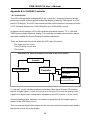
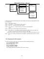
PWS-1409/1419 User’s Manual PWS-1419/1409 9-slot 14.1” TFT LCD Portable Worstation Advantech Portable Workstation User’s Manual 1 PWS-1409/1419 User’s Manual The information contained in this document is believed to be accurate. However, no responsibility is assumed for its use, nor for any infringements of patents or other rights of third party which may result from its use. This information is subject to change without any notice. Safety Instructions 1. Read these safety instructions carefully. 2. K eep this User's Manual for later reference. 3. Disconnect this equipment from any AC outlet bef ore cleaning. Use a damp cloth. Do not use liquid or spray detergents for cleaning. 4. For plug-in equipment, the power outlet s ocket must be located near the equipment and mus t be easily accessible. 5. K eep this equipment away f rom humidity. 6. P ut this equipment on a reliable surface during installation. Dropping it or let -tingit fall may cause damage. 7. The openings on the enc losure are for air conv ection. Protect the equipmentf rom overheating. DO NOT COVER THE OPENINGS. 8. Make sure the voltage of the power source is correct bef ore connecting the equipment to the power outlet. 9. Position the power cord so that people cannot step on it. Do not place any thing over the power cord. 10. A ll cautions and warnings on the equipment should be noted. 11. I f the equipment is not used for a long time, disconnect it from the power s ource to avoid damage by t ransient overvoltage. 12. Never pour any liquid into an opening. This may cause fire or electrical s hock. 13. Never open the equipment. For safety reasons, the equipment should be opened only by qualified service personnel. 14. If one of the following situations arises, get the equipment checked by service pers onnel: a. The power cord or plug is damaged. b. Liquid has penet rated into the equipment. c . The equipment has been exposed to moisture. d. The equipment does not work well, or you c annot get it to work accordingto t he user's manual. e. The equipment has been dropped and damaged. f . The equipment has obvious signs of breakage. The sound pressure level at the operator's position according to IEC 704-1:1982 is no more than 70dB (A). DISCLAIMER: This set of instructions is given according to IE C 704-1. Advan-tech disclaims all re sponsibility for the accuracy of any statements contained herein. 2 PWS-1409/1419 User’s Manual Chapter 1 Getting Started 1-1 Specification 1-2 Before You Start 1-3 Precautions 1-3-1 Power Connections 7 8 8 8 1-3-2 Non-Autosensing Power Supply 8 1-3-3 ATX Power Switch 8 1-3-4 Ventilation 9 1-3-5 Care for the LCD 1-4 Tools and Supplies Needed 1-5 Subassembly Contents 1-6 Parts Contents 1-6-1 Optional Slim FDD, CD ROM 1-6-2 Optional Slim FDD kit 1-6-3 Optional ROM Kit 1-7 Identifying Parts and Controls 1-7-1 Opening the Side Access Covers 1-7-1-a PWS1419 1-7-1-b PWS1409 1-7-2 Side View 1-7-2-a PWS1419 1-7-2-b PWS1409 1-7-3 Front View 1-7-3-a PWS1419 1-7-3-b PWS1409 1-8 Detaching the Keyboard 1-8-1 PWS1419 1-8-2 PWS1409 1-8-2-a The Standard Keyboard . 1-8-2-b The Optional Industrial Silicon Rubber Keyboard Chapter 2 9 9 9 9 10 10 10 11 11 11 11 12 12 12 13 13 14 15 15 15 16 16 PWS-1409 Construction 2-1 Opening The Chassis 17 2-1-1 Removing the Back Cover 17 2-1-2 Removing the Card Stabilizers 17 2-2 Identifying the Internal Parts 17 2-3 Removing the CD ROM Cage 18 2-4 Removing the Hard Driver and Slim Floppy Drive Cage 18 2-5 Installing the Backplane 18 2-6 Installing the Standoffs 18 3 PWS-1409/1419 User’s Manual 2-7 Connecting the Power Connector 20 2-8 Installing the Slim CD ROM to the CD ROM Cage 20 2-9 Installing the CD ROM Cage 22 2-10 Installing Drives in the Drive Cage 22 2-11 Installing the Hard Drive 23 2-12 Installing the Slim Floppy Disk Drive 23 2-13 Installing the Drive Cage into the Case 25 2-14 Installing the SBC 26 2-14-1 Setting your SBC Jumpers 26 2-15 Installing the Add-on Cards 27 2-16 Installing the Card Stabilizers 27 2-17 Preparing to Start the System 28 2-17-1 Connecting the Video and Input Devices 2-17-2 Closing the Back Cover 28 29 Chapter 3 PWS-1409 Construction 3-1 Opening The Chassis 3-1-1 Removing the Back Cover 3-2 Removing the Card Stabilizers 3-3 Identifying the Internal Parts 3-4 Removing the Drive Cage 3-5 Installing the Backplane 3-5-1 Installing the Standoffs 3-6 Connecting the Power Connector 3-7 Installing the Drives to the Drive Cage 3-8 Insttalling the Driver Cage into the Case 3-9 Installing the SBC 3-9-1Setting your SBC Jumpers 3-10 Installing the Add-on Cards 3-11 Installing the Card Stabilizers 3-12 Preparing to Start the System 3-12-1 Connecting the Video and Input Devices 3-13 Closing the Back Cover Chapter 4 Using The System Controls 4 31 31 31 31 31 32 32 34 34 36 37 37 38 38 39 39 40 PWS-1409/1419 User’s Manual 4-1 Starting your System 4-1-1 Systems with ATX Power Supply 4-2 OSD Controls 4-2-1 Adjusting the OSD Parameters 4-3 Changing Filter for the internal Fan 4-3-1 PWS-1419 4-3-2 PWS-1419 42 42 43 43 43 43 44 Appendix A. Trouble shooting A-1 Trouble Shooting Techniques A-1-1 No screen after pressing front power switch A-1-1-a Power supply fan not spinning: A-1-1-b Power supply fan is spinning and LCD has no backlight A-1-1-c Power supply fan is spinning and LCD has backlight and power LED is on: A-1-2 LCD screen shows garbage or bad characters or vertical horizontal color lines or bar: A-1-3 LCD screen works fine in Windows but acted funny when running certain programs or games: A-1-4 The display is not on the LCD center A-2 Keyboard and pointing device not responding 46 46 46 46 46 46 47 47 47 Appendix B: LCD VIDEO Controller B-1 Introduction B-2 Safety Precautions B-3Configuring Your Controller B-3-1 LCD with TTL Interface B-3-2 LCD wits LVDS Receiver Interface B-4 OSD Controls B-4-1 Adjusting the OSD Parameters 5 49 50 50 50 50 50 51 PWS-1409/1419 User’s Manual Chapter 1 Getting Started 1-1 Specification 1-2 Before You Start 1-3 Precautions 1-3-1 Power Connections 7 8 8 8 1-3-2 Non-Autosensing Power Supply 8 1-3-3 ATX Power Switch 8 1-3-4 Ventilation 9 1-3-5 Care for the LCD 1-4 Tools and Supplies Needed 1-5 Subassembly Contents 1-6 Parts Contents 1-6-1 Optional Slim FDD, CD ROM 1-6-2 Optional Slim FDD kit 1-6-3 Optional ROM Kit 1-7 Identifying Parts and Controls 1-7-1 Opening the Side Access Covers 1-7-1-a PWS1419 1-7-1-b PWS1409 1-7-2 Side View 1-7-2-a PWS1419 1-7-2-b PWS1409 1-7-3 Front View 1-7-3-a PWS1419 1-7-3-b PWS1409 1-8 Detaching the Keyboard 1-8-1 PWS1419 1-8-2 PWS1409 1-8-2-a The Standard Keyboard . 1-8-2-b The Optional Industrial Silicon Rubber Keyboard 6 9 9 9 9 10 10 10 11 11 11 11 12 12 12 13 13 14 15 15 15 15 15 PWS-1409/1419 User’s Manual Chapter 1 Getting Started 1-1 General Features Support passive backplane form factor platforms. 14.1” High resolution color matrix TFT LCD display Built-in analog to digital VGA signal conversion board Add-on card retention system. Shock mount protection for the hard disk driver Detachable 104/105-keys keyboard (water-resistant optional). Built-in keyboard pointing device. Built-in speaker with amplifier 200W ATX power supply (optional DC power supply) Carrying case with wheel. All aluminum constructed chassis.( for PWS -1419 only) Rubber bumper protected corners.( for PWS -1419 only) 3mm Impact-resistant LCD screen w/ tempered glass( for PWS -1419 only) ABS plastic housing with aluminum internal chassis. ( for PWS -1409 only) Environment Operating temperature: -8C to 60C, 10-80% humidity Storage temperature: -20C to 60C, 5-95% humidity Dimensions & Weight PWS-1419 PWS- 1409 Dimensions: 16.6”/421mm (W) 12.1”/282mm (H) 9.1”/ 230mm (D) Weight: 21lbs SKD; approx. 26lbs system Dimensions: 15.7”/399mm (W) 13.2”/335mm (H) 10.4”/ 264mm (D) Weight: 18lbs SKD; approx. 22lbs system 7 PWS-1409/1419 User’s Manual 1-2 Before You Start The major component of the subassembly is the chassis, which comes in two models—8x ISA/ 1 CPUslot or 4 x PCI/ 4 ISA/1 CPU slot Passive Backplane. The chassis comes pre-assembled with an active matrix LCD, LCD controller, power supply, keyboard, ventilation fans and internal speaker. To complete the system, you must add a system board, CPU and peripheral devices. Before adding these devices, it is important to follow certain basic safety precautions. You should become familiar with the chassis both externally and internally. And you should also have the right tools available to you. 1-3 Precautions 1-3-1 Power Connections The major component of the subassembly is the chassis, which comes in two models— 8x ISA/ 1 CPUslot or 4 x PCI/ 4 ISA/1 CPU slot Passive Backplane. The chassis comes preassembled with an active matrix LCD, LCD controller, power supply, keyboard, ventilation fans and internal speaker. To complete the system, you must add a system board, CPU and peripheral devices. Use Supplied Power Cord The subassembly is shipped with a power cord compatible with the AC wall outlet in your region. 1-3-2 Non-Autosensing Power Supply Before plugging in the power cord, examine the power supply to see if you have an autosensing or non-autosensing power supply. Autosensing power supplies automatically adjust to the AC constructed of metal and provide front impact protection for outlet voltage. If your subassembly is shipped with a nonautosensing power supply, there will be a voltage selector switch located near the AC power connector. Make sure it’s set to the appropriate voltage setting for your power outlet. 1-3-3 ATX Power Switch The power supply shipped with the ATX chassis may or may not have an ON/OFF switch. To power up your system where the power supply has an ON/OFF switch, you must first press the switch to the ON position and then press the ATX power up/down switch located on the front to start your system. The ATX power switch found on the front of the chassis DOES NOT turn off the AC power. To remove AC power from your system, you must unplug the AC power cord from the AC outlet or the chassis. 8 PWS-1409/1419 User’s Manual 1-3-4 Ventilation The chassis comes with three intake fans and one power supply exhaust fan providing cooling and air flow. When operating the system, never block any ventilation openings. Always leave enough room around the chassis to allow adequate air flow. 1-3-5 Care for the LCD The chassis comes with a pre-assembled active matrix LCD. Liquid crystal displays are made of glass which will break or crack if mishandled. During system assembly, keep the keyboard latched to the chassis. The keyboard housing is constructed of metal and provides front impact protection for the LCD during transportation. 1-4 Tools and Supplies Needed Before beginning your work, make sure you have the following tools and supplies available: ƒÜ ƒÜ #2 Phillips (cross head) screwdriver. An anti-static wrist strap (recommended). 1-5 Subassembly Contents ƒ Ü The subassembly consists of, ƒ Ü This subassembly guide. ƒ Ü Chassis with pre-assembled LCD, LCD controller, power supply, cooling fans, internal speaker and keyboard with integrated pointing device. ƒ Ü Power cord. ƒ Ü Carry case. ƒ Ü Parts for installing motherboard and drives. ƒ Ü See Appendix for technical specifications. 1-6 Parts Contents The subassembly parts kit contains the following hardware for installing boards and drives. 1. Round head screw 2Ö long (for securing CD ROM interface board) 2. Round head screw (for securing backplane on the standoff, interface board). 3. Metal washer (use with the flat head and round head screws for mounting the drives) 4. Insulating washer (when installing the motherboard use it with the round head screw 4). 5. Flat head screw (for securing hard driver). 6. Black round head screw (securing driver cage to side of case, CD ROM cage to the case) 7. Black flat screw (securing driver cage to the bottom of the case, back cover) 8. Round head screw 2.5Ö (for securing slim floppy disk) 9. Motherboard Standoff 10. Round head screw 2Ö short (for securing slim CD ROM) 9 PWS-1409/1419 User’s Manual 1-6-1 Optional Slim FDD, CD ROM Optional Slim Floppy Disk Kit 1. Floppy disk power cable 2. Floppy interface board 3. Floppy disk signal cable (from interface to disk) 4. Slim floppy disk 1-6-2 Optional Slim CD ROM Disk 1. Slim CD ROM interface board 2. CD ROM power cable (interface to power supply) 3. Audio cable (interface board to sound card or SBC Audio out) 4. Slim CD ROM 1-6-3 Optional Slim FDD + Slim CD ROM Disk 1. Floppy disk signal board (from interface to disk) 2. Floppy interface board 3. Power cable for Slim floppy disk and CD ROM. (power supply to Floppy disk and slim CD ROM 4. Slim floppy disk 5. Audio cable (interface board to sound card or SBC Audio out) 6. Slim CD ROM interface board 7. Slim CD ROM 10 PWS-1409/1419 User’s Manual The pin out may be different for other brand or version of CD ROM & floppy disk Do not use the CD ROM and floppy from other sources. 1-7 Identifying Parts and Controls 1-7-1 Opening the Side Access Covers 1-7-1-a PWS-1419 The side access covers provide side impact protection for to the chassis. The access covers must be opened to access the external drive bays and I/O connectors. Turn the thumbscrew in the counter clockwise direction to open the access covers. Then swing out toward the back. The access covers are not interchangeable. When operating your system, remove any side cover that does not have ventilation holes to allow adequate air flow. 1-7-1-b PWS-1409 The side access door provide side impact protection for the chassis. The access door must be opened to access the I/O connectors. Turn the thumbscrew in the counter clockwise direction to open the access covers. They swing out toward the back. 11 PWS-1409/1419 User’s Manual 1-7-2 Side Views 1-7-2-a PWS-1419 Use the photo below to identify components and I/O ports that are accessible from the two sides of the 1419T chassis. The illustration shows the external connectors and components of a completely assembled SBC system. Your subassembly has only knockout holes instead. 1. Slim Floppy disk. 9. Internal speaker connector 10. Two intake fans w/ Filter 11. Slim CD ROM 12. Power switch 13. AC power Input Socket 14. Power Fan 2. 10 add-on card slot 3. I/O port knockouts. 4. Keyboard release latches 5. VGA port & monitor connector 6. Serial port. 7. PS/2 keyboard port and Mouse 1-7-2-b PWS-1409 Handle bar VGA port & monitor connector 9 add-on card slot (optional 12) I/O port knockouts. Internal speaker connector AC power Input Socket Power switch Power Fan ATX Power switch 12 PWS-1409/1419 User’s Manual reset switch Tone Volume 3 intake fans w/ Filter CDROM 3.5” Floppy disk. The CDROM is on the right side of the panel 1-7-3 Front View 1-7-3-a PWS-1419 You access the front panel controls by first disengaging the keyboard. Disengage the keyboard from the latches by sliding the latch tabs on both sides of the chassis upwards as shown and simultaneously pull the top part of the keyboard away from the chassis. The keyboard is still hinged on the bottom by latch bolts. Lay down the keyboard. On the front side of the chassis you’ll find the following controls and subassembly elements: 1. Power ON LED (when on, indicates power delivered to the system) 2. IDE hard disk activity LED (when blinking, indicates disk activity is occurring). 3. On-screen-display (OSD) menu controls. 4. System reset switch (when pressed, reboots and initializes the system. 5. ATX power switch (powers the system up and down). 6. Keyboard latch bolt release pegs. 13 PWS-1409/1419 User’s Manual 1-7-3-b PWS-1419 You access the front panel controls by first disengaging the keyboard. Disengage the keyboard from the latches by sliding the latch tabs on the bottom sides of the keyboard towards the center as shown and simultaneously pull the top part of the keyboard away from the chassis. The keyboard is still hinged on the bottom by latch bolts. Lay down the keyboard. On the front side of the chassis you’ll find the following controls and subassembly elements: Push theKeyboard Latches to center Pull up the keyboard stand Power LED HDD LED TFT LCD Keyboard LED Indicator keyboard stand Touch Pad Keyboard latches Anti-slipper Rubber Knob 1-7-3-c OSD button on PWS-1409 The OSD button is on the left side of the panel, you have to pull up the panel first to see the buttons, pull down the small door and pull up the panel with the small bar on the panel. OSD Buttons “ Manual” “Select” “+” “-“ Pull up the bar Pull out Small door 14 PWS-1409/1419 User’s Manual 1-8 Detaching the Keyboard 1-8-1 PWS- 1419 The keyboard is detachable. Normally it’s locked to the chassis by two latch bolts. You can detach the keyboard by sliding both release pegs towards each other, compressing the latch bolts until they slide out of the slots. Pull the keyboard away from the chassis and release the pegs. The subassembly comes with either the STANDARD keyboard, a mechanical switch keyboard with an integrated pointing device, or with an OPTIONAL membrane keyboard. 1-8-1-a The Standard Keyboard 1-8-1-b The Optional Industrial silicon rubber Keyboard Touch Pad Point Device 1-8-2 PWS- 1409 The subassembly comes with a mechanical switch keyboard with an integrated touch pad device. The signal cable is conceal in the fillister of the keyboard, you have pull it up to connect the connector of the SBC. The concealed cable touch pad 15 PWS-1409/1419 User’s Manual Chapter 2 PWS-1409T Construction 2-1 Opening The Chassis 17 2-1-1 Removing the Back Cover 17 2-1-2 Removing the Card Stabilizers 17 2-2 Identifying the Internal Parts 17 2-3 Removing the CD ROM Cage 18 2-4 Removing the Hard Driver and Slim Floppy Drive Cage 18 2-5 Installing the Backplane 18 2-6 Installing the Standoffs 18 2-7 Connecting the Power Connector 20 2-8 Installing the Slim CD ROM to the CD ROM Cage 20 2-9 Installing the CD ROM Cage 22 2-10 Installing Drives in the Drive Cage 22 2-11 Installing the Hard Drive 23 2-12 Installing the Slim Floppy Disk Drive 23 2-13 Installing the Drive Cage into the Case 25 2-14 Installing the SBC 26 2-14-1 Setting your SBC Jumpers 26 2-15 Installing the Add-on Cards 27 2-16 Installing the Card Stabilizers 27 2-17 Preparing to Start the System 28 2-17-1 Connecting the Video and Input Devices 2-17-2 Closing the Back Cover 28 29 16 PWS-1409/1419 User’s Manual Chapter 2 PWS-1409T Construction 2-1 Open the chassis 2-1-1 Removing the Back Cover Face the back of the chassis. Remove all screws as shown. There are 10 screws along the perimeter of the back cover that holds the back cover to the chassis. Always power-down the system. Always turn off any peripheral devices connected to the system. Always unplug the AC power cord from the chassis. Face the back of the chassis. Remove all the release screws as shown. There are 10 screws along the perimeter of the back cover that secures it to the chassis. 2-2 Removing the Card Stabilizers The stabilizer is designed to securely hold down add-on cards in their expansion slots with plastic hold-down clips. The stabilizer must be removed prior to adding boards and components in the chassis. Step 1. Remove the card stabilizer release screws as shown. Step 2. Remove the stabilizer and set them aside. 2-3 Identifying the Internal Parts 1. 2. 3. 4. 5. 4 2 5 1 3 17 Power supply Slim CD ROM drive holder (2pcs) Slim Floppy drive holder Internal Cooling fan LCD power connector (to power supply) PWS-1409/1419 User’s Manual 2-3 Removing the CD ROM cage Step 1. Remove screws as shown (1) and then pull out the CD ROM Upper cage. Step 2. Remove screw as shown (2) and then pull out the CD ROM Bottom cage. 2-4 Removing the hard drive and slim floppy Drive cage Lay the chassis on your work area so that you have access to the bottom side. Remove the 4 screws and take out the cage. After you removed the slim CD ROM cage and Drives cage from the chassis, set them aside. Your are now ready either to install the drives in the drive cage or install the backplane. 2-5 Installing The Backplane Make sure that at no time you are working on any electrical or electronic components while any part of the system is energized. Always disconnect the power! Use caution to protect the delicate electronic components. Ground your self during the installation of the motherboard and other components. 2-6 Installing the Standoffs #9 Standoffs #2 3x4 screws to tighten backplane #4 Washer between the backplane and screws Take a moment to study the inside of the chassis, making note of the location of the keyboard Connector if it come with backplane. Step 1. Slant the backplane retention into the chassis and position it in the area it will be installed, making sure the alignment of the slots and connectors is correct. Step 2. Make sure the location of the backplane mounting points. You are going to install standoffs at those mounting points. 18 PWS-1409/1419 User’s Manual find the mount point of the backplane insert the stand offs Thread clock-wise to insert the standoff reverse to take off the stand off Your package comes with metal standoffs threaded on one end and tapped on the opposite end to receive a mounting screw. Step 3. Now carefully withdraw the backplane and thread the standoffs into the mounting holes in the chassis. Step 4. Align the mounting pointing points and insert the screws into the metal standoffs. Step 5. Tighten the screws. (add washer if the screws will short with the circuit of the backplane) Slant the backplane and lower the backplane into the chassis motherboard. Turn clockwise to secure the screws you may insert the insulating washer between the screw and backplane to avoid the shorting 19 PWS-1409/1419 User’s Manual 2-7 Connecting the power Connector The plug from the power supply will only insert in one orientation. Push down firmly making sure the hook on the terminal block clips onto the plug. Connecting the Chassis Cables The chassis has 3 internal cooling fan to reduce the temperature of the system, connecting the fan power connector to fan adapter board. The flat panel display receives its power from the power supply. Find the wire bundle that ends in a 4-pin power connector from the chassis side and plug it into one of the power supply connectors. 2-8 Installing the slim CD ROM to the CD ROM Cage Step 1. Take back the CD ROM cage, take the #10 screw from your package, and secure the CD ROM to CD ROM cage Step 2. Take the CD ROM interface board and Screw #1 from your package, and fix the interface board to CD ROM Step 3. Connect the cables to CD ROM interface board Interior space is going to be tightened. While you have the CD ROM cage outside of the chassis, plug in all the cables. Power supply plugs and audio cable will only insert in one orientation. Ribbon cables should always be connected with the colored stripe to Pin 1 on the connectors. 20 PWS-1409/1419 User’s Manual What need for install CDROM #1 fix interface board to CD ROM #10 fix CD ROM to CD ROM cage #6 fix CD ROM bottom cage to side of case #7 Fix CD ROM upper cage to back of case 1. CD ROM upper cage 2. CD ROM bottom cage 1. 2. 3. 4. 5. Connect to sound card or SBC “CD in” Connect to power supply Connect to floppy interface board Connect to IDE signal cable CD ROM interface board # 10 screws to secure upper cage and CD ROM secure Bottom cage and CD ROM Connect the cables Use #1 screws to secure interface board to CD ROM 21 PWS-1409/1419 User’s Manual 2-9 Installing the CD ROM Cage Step Step Step Step 1. 2. 3. 4. Carefully put the drive cage back into the chassis. (fig1) Align the side mounting holes. Insert the screw#6 and tighten it Align the back mounting holes. Insert the screw#7 and tighten it Use the cable to tighten the signal cable (fig3) Put the cage back to case carefully Insert the screw to fix the CD ROM cage Tighten the signal cable 2-10 Installing Drives in the Drive Cage Take back the drive cage, take thefloppy interface board, signal cable and screws from your package, and secure the drives to driver cage 22 PWS-1409/1419 User’s Manual 2-11 Installing the hard driver The drive cage supports one slim Floppy disk and a 3.5” Hard disk drives. Step 1. Take back the driver cage and take off the screw#5 and washer #3 from your package. Step 2. Insert the hard drives to drive cage. Step 3. Align the mounting holes and insert the screws# 5 (please insert the washer #3 for shock-mount protect. Tighten the screws. Insert the screw #5 to secure hard drive to driver cage (insert the metal washer #3 between the cage and screw, it’s a shock mount design for the hard driver There are a small copper pipe inside the rubber , make sure it is still in the rubber. FCB shows the mounting pointsfor floppy interface board The other side will be same as above 2-12 Installing the slim floppy disk driver Step 1. Take off the floppy drive interface board, floppy interface board, Screw #8, #2 from the package. Step 2. Align the mounting holes and insert the screws# 8 to fix the slim floppy disk The other side Use screws #8 to secure the floppy 23 PWS-1409/1419 User’s Manual Step 3. Pull up the small cage from the slim floppy disk Connect the signal cable The cable has pin 1 on the dot point Pull up the small cage carefully Step 4. Insert the floppy signal cable to slim floppy. Ribbon cables should always be connected with the colored stripe (blue point on it) to Pin 1 on the connectors Step 5. Push back the cage Pushback the small cage of floppy drive Push back the small cage Step 6. Connect the signal cable to the interface board by the same method Step 7. Slant the interface board 180°, let the power connector upward Connect the cable to the interface card the dots are the pin1 of cable Slant the interface 180° Step 8. Measure the length of the signal cable, tape it on the floppy driver Step 9. Align the mounting holes and insert the screws# 2 to secure the floppy interface board Secure the interface board with screw #2 Tape the signal cable 24 PWS-1409/1419 User’s Manual Step10. Connect the signal cable Step11. Connect the power cable 2-13 Installing the Drive cage into the case Step 1. Connect the hard drive signal cable and power cable Interior space is going to be tightened. While you have the drive cage outside the chassis, plug in hard drive signal and power cable Power supply plugs cable will only insert in one orientation. Ribbon cables should always be connected with the colored stripe to Pin 1 on the connectors for the signal cable. Step 2. Carefully put the drive cage back into the chassis. Step 3. Align the back and bottom mounting holes.it 1. Lay the chassis on your work area so that you have access to the bottom side. 2. Insert the screw #6 into the points 25 PWS-1409/1419 User’s Manual 2-14 Installing the SBC 2-14-1 Setting your SBC Jumpers Before installing the motherboard in the chassis, install the CPU and set any dip-switch or jumper on the SBC. Since jumper and dip-switch settings are board-specific, consult the manual that comes with the SBC and carefully follow the directions to configure your SBC. Make sure that at no time you are working on any electrical or electronic components while any part of the system is energized. Always disconnect the power! Use caution to protect the delicate electronic components. Ground your self during the installation of the motherboard and other components. Installing the Standoffs Step1. Locate the slot on the backplane you wish to use. Remove the slot cover screw and then remove Step 2. Set the card jumpers or switches according to the manufacturer’s requirements if necessary. Step 3. Connect of the small cables from the chassis. The cables are color coded and labeled. Consult your SBC manual to connect these cables to the correct set of terminal pins. It may be difficult to know for sure that the polarity of the LED connections is correct. If an LED fails to light when it should during the test phase, you will be able to shut down and reverse connections as needed. 1. 2. 3. 4. 5. Power-on indicator LED (orange and black). Hard disk LED (blue and black) System reset switch (white and black). Power switch (yellow and white). Internal PC speaker (blue and white). STEP 4. Connect the driver signal cable to SBC Connect the CD ROM, floppy drive, hard disk driver signal cable to the SBC before the SBC fix. The ribbon cables should always be connected with the colored stripe to Pin #1 on the connectors. Step 5. Hold the card and align the edge connectors with the slot. Firmly push the card into the slot. Step 6. Use the screw removed earlier. Insert it into the threaded hole and tighten it. 26 PWS-1409/1419 User’s Manual Connect the signal cable and chassis cable before fix the SBC Fix the SBC with screw #2 2-15 Installing the Add-on Cards The chassis has 10 slot openings supporting up to nine (one is used by SBC) add-on cards. Follow these steps to install add-on cards Add-on card can be extremely sensitive to electrostatic discharge. Always handle the cards with care. Hold the card by the metal slot cover or upper corners. Be careful not to touch the components or gold edge connectors. Step 1. Locate the slot on the backplane you wish to use. Remove the slot cover screw and then remove the slot cover. Step 2. Set the card jumpers or switches according to the manufacturer’s requirements if necessary. Step 3. Hold the card and align the edge connectors with the slot. Firmly push the card into the slot. Step 4. Use the screw removed earlier. Insert it into the threaded hole and tighten it. 2-16 Installing the Card Stabilizers The procedures of Installing the Card Stabilizers The card stabilizers are designed to hold down the add-on cards securely in their slots by pressing the card edges with plastic clips. After you’ve installed all the add-on cards, reinstall the stabilizers using the following steps. Step 1. Loosen the screws that hold the plastic clips in their brackets. The clips should be able to slide freely inside the brackets. Step 2. Align the stabilizer bars with their mounting holes on the chassis. Insert the mounting screws and tighten them. You may have to pull some of the clips up to leave enough space between the clip and the card edge. 27 PWS-1409/1419 User’s Manual Slant the add-on card stabilizer and put it in the case, then set straight and fix it. Use screw #7 to secure it. Use the screw removed earlier. Insert it into the threaded hole and tighten it. Step 3. Slide each clip so they come in contact with the top edge of the add-on cards. While holding the clip firmly against the card edge, tighten the bracket screws. Step 4. Cut off any excessive part of the plastic clip. Step 5. Repeat these steps for the other stabilizer. Press the plastic extender firmly against the card edge and tighten screw. 2-17Preparing to Start the System Cut off any excessive part of the plastic clip. 2-17-1 Connecting the Video and Input Devices The location of your video output, keyboard and pointing device connectors are board dependent. Connect the video cable to the VGA output connector on your SBC or other graphics card. Connect the keyboard and pointing device connectors to their sockets and firmly push them into the sockets. 28 PWS-1409/1419 User’s Manual 1. Connect the VGA Connector 2. Connect the input device 3. Connect the other connectors for other device such as Ethernet, Audio device….. 2-17-2 Closing the Back Cover Reinstall the back cover and insert the retaining screws. 29 PWS-1409/1419 User’s Manual Chapter 3 PWS-1409 Construction 3-1 Opening The Chassis 3-1-1 Removing the Back Cover 3-2 Removing the Card Stabilizers 3-3 Identifying the Internal Parts 3-4 Removing the Drive Cage 3-5 Installing the Backplane 3-5-1 Installing the Standoffs 3-6 Connecting the Power Connector 3-7 Installing the Drives to the Drive Cage 3-8 Insttalling the Driver Cage into the Case 3-9 Installing the SBC 3-9-1Setting your SBC Jumpers 3-10 Installing the Add-on Cards 3-11 Installing the Card Stabilizers 3-12 Preparing to Start the System 3-12-1 Connecting the Video and Input Devices 3-13 Closing the Back Cover 30 31 31 31 31 31 32 32 34 34 36 37 37 38 38 39 39 40 PWS-1409/1419 User’s Manual Chapter 3 PWS-1409 Construction 3-1 Open the chassis 3-1-1 Removing the Back Cover Face the back of the chassis. Remove all screws as shown. There are 7 screws along the perimeter of the back cover that holds the back cover to the chassis. Always power down the system. Always turn off any peripheral devices connected to the system. Always unplug the AC power cord from the chassis. Face the back of the chassis. Remove all the release screws as shown. There are 7 screws along the perimeter of the back cover that secures it to the chassis. 3-2 Removing the Card Stabilizers The stabilizer is designed to securely hold down add-on cards in their expansion slots with plastic hold-down clips. The stabilizer must be removed prior to adding boards and components in the chassis. Step 1. Remove the card stabilizer release screws as shown. Step 2. Remove the stabilizer and set them aside. 3-3 Identifying the Internal Parts After you remove the card stabilizer you can check the case contains, the figure is on the next page. The CDROM cable and audio cable will come with the slim CDROM option. 3-4 Removing the Drive cage Remove the 2 screws and take out the cage. After you removed the drivers cage from the chassis, set it aside. Your are now ready either to install the drives in the drive cage or install the backplane. 31 PWS-1409/1419 User’s Manual 1 3 4 13 1 1. speaker 2 case fan 3 fan board 4 LCD power cable 5 audio cable CD audio in 6 driver cage 7 fan cable to SBC 8 CDROM signal cable 9 power supply 10 reset cable 11 audio cable (SBC to speaker) 12 side door 13 mount hole 2 2 2 5 6 7 8 9 10 11 12 3-5 Installing The Backplane Make sure that at no time you are working on any electrical or electronic components while any part of the system is energized. Always disconnect the power! Use caution to protect the delicate electronic components. Ground your self during the installation of the motherboard and other components. 3-5-1 Installing the Standoffs #9 Standoffs #2 3x4 screws to tighten backplane #4 Washer between the backplane and screws Take a moment to study the inside of the chassis, making note of the location of the keyboard Connector if it come with backplane. Step 1. Slant the backplane retention into the chassis and position it in the area it will be installed, making sure the alignment of the slots and connectors is correct. Step 2. Make sure the location of the backplane mounting points. You are going to install standoffs at those mounting points. 32 PWS-1409/1419 User’s Manual find the mount point of the backplane insert the stand offs Thread clock-wise to insert the standoff reverse to take off the stand off Your package comes with metal standoffs threaded on one end and tapped on the opposite end to receive a mounting screw. Step 3. Now carefully withdraw the backplane and thread the standoffs into the mounting holes in the chassis. Step 4. Align the mounting pointing points and insert the screws into the metal standoffs. Step 5. Tighten the screws. (add washer if the screws will short with the circuit of the backplane) Slant the backplane and lower the backplane into the chassis Turn clockwise to secure the screws you may insert the insulating washer between the screw and backplane to avoid the shorting 33 PWS-1409/1419 User’s Manual 3-6 Connecting the power Connector The plug from the power supply will only insert in one orientation. Push down firmly making sure the hook on the terminal block clips onto the plug. Connecting the Chassis Cables The chassis has 3 internal cooling fan to reduce the temperature of the system, connecting the fan power connector to fan adapter board. The flat panel display receives its power from the power supply. Find the wire bundle that ends in a 4-pin power connector from the chassis side and plug it into one of the power supply connectors. 3-7 Installing driver disk to the drive Cage Step 1. Take back the driver cage, take the screw#5 and washer #3 from your package, and secure the hard disk to driver cage Step 2. Take the floppy disk and Screw #2 from your package, and secure the floppy disk to the drive cage. Step 3. Connect trhe cables to hard disk and floppy disk. Interior space is going to be tightened. While you have the drivers outside of the chassis, plug in the signal cables. Ribbon cables should always be connected with the colored stripe to Pin 1 on the connectors. 34 PWS-1409/1419 User’s Manual secure the hard disk to drive cage with screw # 5, insert washer #3 between cage and screw, same with the other side secure the floppy disk to drivr cage with screw# 2, , same with the other side Connect the signal cables Ribbon cables should always be connected with the colored stripe to Pin 1 on the connectors. 35 PWS-1409/1419 User’s Manual 3-8 Intall the driver cage to case Step Step Step Step 1. Carefully put the drive cage back into the chassis. 2. Plugging the case fan power conecttor into the interface board for fan power 3. Plugging the power conector for floppy disk and hard disk 4. Align the mounting holes and insert the screws # 2 connect the case fan power connect (black arrow) to the interface board (white arrow) CONNECT THE DRIVE POWER CONNECTOR Align the mounting holes and insert the screws # 2 36 PWS-1409/1419 User’s Manual 3-9 Installing the SBC 3-9-1 Setting your SBC Jumpers Before installing the motherboard in the chassis, install the CPU and set any dip-switch or jumper on the SBC. Since jumper and dip-switch settings are board-specific, consult the manual that comes with the SBC and carefully follow the directions to configure your SBC. * Make sure that at no time you are working on any electrical or electronic components while any part of the system is energized. Always disconnect the power! Use caution to protect the delicate electronic components. Ground your self during the installation of the motherboard and other components. IInstalling the Standoffs Step1. Locate the slot on the backplane you wish to use. Remove the slot cover screw and then remove the slot cover. Step 2. Set the card jumpers or switches according to the manufacturer’s requirements if necessary. Step 3. Connect of the small cables from the chassis. The cables are color coded and labeled. Consult your SBC manual to connect these cables to the correct set of terminal pins. It may be difficult to know for sure that the polarity of the LED connections is correct. If an LED fails to light when it should during the test phase, you will be able to shut down and reverse connections as needed. 1. 2. 3. 4. 5. Power-on indicator LED (orange and black). Hard disk LED (blue and black) System reset switch (white and black). Power switch (yellow and white). Internal PC speaker (blue and white). Step 4. Connect the drive signal cable to SBC Connect the CD ROM, floppy drive, hard disk drive signal cable to the SBC before the SBC fix. The ribbon cables should always be connected with the colored stripe to Pin #1 on the connectors. Step 5. Hold the card and align the edge connectors with the slot. Firmly push the card into the slot. Step 6. Use the screw removed earlier. Insert it into the threaded hole and tighten it. 37 PWS-1409/1419 User’s Manual Connect the signal cable and chassis cable before fix the SBC Fix the SBC with screw #2 3-10 Installing the Add-on Cards The chassis has 10 slot openings supporting up to nine (one is used by SBC) add-on cards. Follow these steps to install add-on cards Add-on card can be extremely sensitive to electrostatic discharge. Always handle the cards with care. Hold the card by the metal slot cover or upper corners. Be careful not to touch the components or gold edge connectors. Step 1. Locate the slot on the backplane you wish to use. Remove the slot cover screw and then remove the slot cover. Step 2. Set the card jumpers or switches according to the manufacturer’s requirements if necessary. Step 3. Hold the card and align the edge connectors with the slot. Firmly push the card into the slot. Step 4. Use the screw removed earlier. Insert it into the threaded hole and tighten it. 3-11 Installing the Card Stabilizers The procedures of Installing the Card Stabilizers The card stabilizers are designed to hold down the add-on cards securely in their slots by pressing the card edges with plastic clips. After you’ve installed all the add-on cards, reinstall the stabilizers using the following steps. Step 1. Loosen the screws that hold the plastic clips in their brackets. The clips should be able to slide freely inside the brackets. Step 2. Align the stabilizer bars with their mounting holes on the chassis. Insert the mounting screws and tighten them. You may have to pull some of the clips up to leave enough space between the clip and the card edge. There are two set of hole for the plastic clip, one for ISA theo ther for PCI, you can use the right hole according the slot type. 38 PWS-1409/1419 User’s Manual Slant the add-on card stabilizer and put it in the case, then set straight and fix it. Use screw #7 to secure it. Use the screw removed earlier. Insert it into the threaded hole and tighten it. Step 3. Slide each clip so they come in contact with the top edge of the add-on cards. While holding the clip firmly against the card edge, tighten the bracket screws. Step 4. Cut off any excessive part of the plastic clip. Step 5. Repeat these steps for the other stabilizer. Press the plastic extender firmly against the Cut off any excessive part of the plastic clip. card edge and tighten screw. 3-12 Preparing to Start the System 3-12-1 Connecting the Video and Input Devices The location of your video output, keyboard and pointing device connectors are board dependent. Connect the video cable to the VGA output connector on your SBC or other graphics card. Connect the keyboard and pointing device connectors to their sockets and firmly push them into the sockets. 39 PWS-1409/1419 User’s Manual 1. Connect the VGA Connector 2. Connect the other connectors for other device such as Ethernet, Audio device… 3-13 Closing the Back Cover Closing the Back Cover Reinstall the back cover and insert the retaining screws. 40 PWS-1409/1419 User’s Manual Chapter 4 Using The System Controls 4-1 Starting your System 4-1-1 Systems with ATX Power Supply 4-2 OSD Controls 4-2-1 Adjusting the OSD Parameters 4-3 Changing Filter for the internal Fan 42 42 43 43 43 4-3-1 PWS-1419 4-3-2 PWS-1419 43 44 41 PWS-1409/1419 User’s Manual Chapter 4 Using The System Controls 4-1 Starting your System Before starting your system, plug in the power cord and make sure the video and input device connectors are plugged in. Release the keyboard latches and lay it flat on your work area. 4-1-1 Systems with ATX Power Supply If you have an ATX power supply, power up your system by pressing the ATX power switch push button on the front panel of your chassis. power switch(1409/1419 power switcch) ATX switch (1409 only, the ATX power switch is located in the panel, see it in the next picture ) 4-2 OSD Controls The LCD controller includes an integrated RAM-based OSD controller. Through four front panel controls you can view adjustable features of the LCD through the On-Screen Display. Follow these steps to activate the on-screen display and make any adjustments to suit your preference: Step 1. Power up the system. Step 2. Press MENU to invoke the on-screen menu. Step 3. Press SEL to step through the main options. Step 4. Press either + or - button to bring up sub-menus of the highlighted option. Step 5. Press SEL to step through the sub-menu options. Step 6. Press either + or - to modify the selected parameter Pressing a button once increases or decreases the numerical value by a single digit. Holding down a button increases the rate of change. Press MENU to return to the previous screen. Step 7. After you’ve made your adjustments press MENU repeatedly until the OSD is turned off. 42 PWS-1409/1419 User’s Manual Menu Sel Menu + Reset ATX Power Sel + - 4-2-1 Adjusting the OSD Parameters The OSD consists of a main menu and sub-menus with the following selections: Brightness MENU Manual adjustment the brightness CONTRAST MENU Contrast: Manual adjustment the contrast Sub-CONTRAST: Manual adjustment of individual RGB channel contrast. Position MENU H-size: Adjust the horizontal size Clock phase: Manual adjustment of the sample pixel clock phase. H.POSITION: Adjusts the horizontal image position within the display area of the LCD. V.POSITION: Adjusts the vertical image position within the display area of the LCD. Information Show the current display resolution, vertical and horizontal frequency 4-3 Changing Filter for the internal Fan 4-3-1 PWS1419 The internal fan is the entrance of the system air flow. It may contain dust during the long use. Change or clean the filter for the fan will improve the system air flow. Please follow the steps to clean or change the filter. Step 1. The filter is under a metal cage on the right side of case. Step 2. Take off the two screws Step 3. Remove the cage Step 4. Remove the filter Step 5. Replace a new one or you may clean the original one Step 6. Move back the cage, and insert back the screws 43 PWS-1409/1419 User’s Manual Remove the screws Remove the cover, take off the filter Caution: Please make the filter is dry when you restore it 4-3-2 PWS-1419 The internal fan is the entrance of the system air flow. It may contain dust during the long use. Change or clean the filter for the fan will improve the system air flow. Please follow the steps to clean or change the filter. Step 1. The filter is under a plastic cage on the right side of case. Step 2. Take off thescrew Step 3. Remove the cage Step 4. Remove the filter Step 5. Replace a new one or you may clean the original one Step 6. Move back the cage, and insert back the screws Step 1. The second and third filters are under a plastic cage on the right side of case. Step 2. push the side of the plastic cage Step 3. Remove the cage Step 4. Remove the filter Step 5. Replace a new one or you may clean the original one Step 6. Move back the cage, Caution: Please make sure the filter is dry when you restore it 44 PWS-1409/1419 User’s Manual Appendix A. Trouble shooting A-1 Trouble Shooting Techniques A-1-1 No screen after pressing front power switch A-1-1-a Power supply fan not spinning A-1-1-b Power supply fan is spinning and LCD has no backlight A-1-1-c Power supply fan is spinning and LCD has backlight and power LED is on A-1-2 LCD screen shows garbage or bad characters or vertical horizontal color lines or bar A-1-3 LCD screen works fine in Windows but acted funny when running certain programs or games A-1-4 The display is not on the LCD center A-2 Keyboard and pointing device not responding 45 46 46 46 46 46 46 47 47 47 PWS-1409/1419 User’s Manual A-1 Trouble Shooting Techniques A-1-1 No screen after pressing front power switch A-1-1-a Power supply fan not spinning: * Check power source. * Check power cord connection. * Check if all power connectors inside the chassis have been properly connected. * Check the ATX power switch cable to SBC(or motherboard) have been properly connected * Check main power switch on power supply (PS-2 power supply for BP-7 model). * Check the power-on Cable between SBC and backplane (there is a power- on cable between SBC and back plane, check the cable is on the right position and direction) * Check voltage selection if there is one on the power supply unit. A-1-1-b Power supply fan is spinning and LCD has no backlight (Backlight can be observed along the top and bottom edge of the LCD screen.) Check if the power supply to the LCD screen is connected. A-1-1-c Power supply fan is spinning and LCD has backlight and power LED is on Check if the video cable is properly connected. If the system seems to be booting up (hard disk drive cranking up) then detach the video cable to the internal LCD screen and attach to an external good CRT type monitor. If external monitor has video then it is a bad LCD screen or bad internal cabling. If the system does not seems to be booting up (no hard disk activity) and no video when connected to external good CRT monitor, then check system for shorts, reseat video and all other add-on cards. Check memory module installation. Listen for error beeps from the motherboard. If all failed then remove system from the enclosure and check motherboard subassembly with an external set of power supply and display to isolate the problem. Check if the motherboard is not shorted to the standoff. If all failed, call your vendor for support where this enclosure was purchased. A-1-2 LCD screen shows garbage or bad characters or vertical/ horizontal color lines or bar Detach the video connection to the LCD screen and attach to a good external CRT type monitor. If the external CRT monitor shows normal video then it could be compatibility issue. Replace the VGA card and use a different VGA card and try it again with the LCD screen. If it still failed then it could be a bad conversion board or loose cable inside the LCD subassembly. If the external CRT monitor shows similar garbage character then it is a bad video card. (please also check the pins in the 15-pin D-type connector are aligned to the hole of the VGA card) 46 PWS-1409/1419 User’s Manual A-1-3 LCD SCREEN works fine in Windows but acted funny when running certain programs or games: The built-in Intelligent Analog-Digital conversion board (AD board) should adjust the screen to the proper resolution to fill the entire display. However, certain programs or display modes might cause the AD board to not align or sync properly. Check if the program that you are running is running under supported resolution. (The max resolution on 12.1” is 800 * 600, 13. 1”, 14.1”, 15” is 1024 *768. and the vertical frequency should be between 60Hz and 70Hz) You can also try adjusting the OSD to manually adjust the resolution (see Section 6 on Using The Systems Controls). A-1-4 The display is not on the LCD center Adjust the OSD to manually adjust the resolution. Check the VGA output. (The max resolu- tion on 12.1” is 800 * 600, 13.1”, 14.1”, 15” is 1024 *768. and the vertical frequency should be between 60Hz and 70Hz) A-2 Keyboard and pointing device not responding Remove both the PS-2 connections on the motherboard and try using an external regular keyboard and mouse. If an external keyboard or pointing device is working properly then you have a bad keyboard or keyboard cable assembly. There will be 1 Y-type extension cable come wit your SBC, The one-connector end connect to the SBC, and there are 2 connectors for the other end, one is for the keyboard, the other for the touch pad. Make sure that you connect to the right connector. 47 PWS-1409/1419 User’s Manual Appendix B: LCD VIDEO Controller B-1 Introduction B-2 Safety Precautions 49 50 B-3Configuring Your Controller B-3-1 LCD with TTL Interface B-3-2 LCD wits LVDS Receiver Interface B-4 OSD Controls B-4-1 Adjusting the OSD Parameters 50 48 50 50 50 51 PWS-1409/1419 User’s Manual Appendix B: LCD VIDEO Controller B-1 Introduction The LCD video controller subassembly is an “in-monitor” design build around a high performance ASIC technology that enable the display of analog VGA signals on a flat panel LCD display. The LCD video board provides all the electronic necessary to drive a TFT flat panel display from VGA (640x480) up to (1280x1024) source. In feature a multi-interface LCD video controller board that support TTL, LVDS and TMDS protocol-base flat panel display. The controller includes auto resolution adjustment and versatile On-Screen-Display Controller adjustment. There are three basic functional within the LCD video Controller: The video receiver circuit The LCD driver circuit, and The inverter How the LCD Video Controller connects to the LCD screen Inverter LCD Screen LCD Video Controller OSD Interface Board 12V Power Source Analog VGA input source from VGA card A computer’s video interface produces an analog video signal. Since LCD monitors require a digital signal, a video receiver circuit is require to convert the analog video signal into a digital video format that is accepted by the LCD monitor’s driver circuit. Once the analog signal has been converted to a digital format, the digital signal is passed to the LCD driver circuit. This converts the digital video signal into the row and column information that actually that pixels on and off on the display. 49 PWS-1409/1419 User’s Manual The light source for most flat panel displays is a cold cathode fluorescent backlight. These backlights run on high AC voltage provided by an inverter that converts the supplied DC power to AC and steps its voltage up for start-up. Once the backlight is started, the inverter drops the voltage down to its operating level. B-2 Safety Precautions Before you configure and assemble the controller board for your flat panel display, it is important to become familiar with the board layout and also follow certain basic safety precautions Make sure that at no time you are working on any electrical or electronic components while any part of the system is energized Always disconnect the power! Use caution to protect the delicate electronic components. Ground your self during the installation of the motherboard and other components. B-3 Configuring Your Controller While your LCD controller is designed to drive a wide range of TFT LCD panels, many aspects of the ASIC chip’s panel interface are programmable through a micro-controller with built-in EEPROM. Check with the supplier of your controller to find a recommended LCD panel. B-3-1 LCD with TTL Interface Refer to the illustration below to configure your controller board for a LCD that accepts TTL data source. B-3-2 LCD with LVDS Receiver Interface Make sure the kind of receiver of LCD display, and connect it to right connecter. When you use the controller subassembly with a LVDS protocol-based LCD, you must install the daughter board first. It consists of LVDS transmitter ICs that convert CMOS/TTL data into LVDS data stream. Installing the LVDS Daughter Board B-4 OSD Controls The LCD controller includes an integrated RAM-based OSD controller. Through four front panel controls you can view adjustable features of the LCD through the On-Screen Display. 50 PWS-1409/1419 User’s Manual Brightness Contrast Position Information All Reset Brightness Contrast Sub. Contrast H. Size Clock Phase H. Position V. Position R G B Information 1024 x 768 H. f 56.4KHz V. f. 70 Hz Follow these steps to activate the on-screen display and make any adjustments to suit your preference: Step 1. Step 2. Step 3. Step 4. Power up the system. Press MENU to step through the main options. Press SEL to step through the main options. Press either + or – button to bring up sub-menus of the highlighted option. Step 5. Press SEL to step through the sub-menu options. Step 6. Press either + or – to modify the selected parameter value. Pressing a button once increases or decreases the numerical value by a single digit. Holding down a button increases the rate of change. Press MENU to the previous screen. Step 7. After you’ve made your adjustments press MENU repeatedly until the OSD is turned off. B-4-1 Adjusting the OSD Parameters The OSD consists of a main menu and sub-menus with the following selections: 8-4-1-a BRIGHTNESS MENU Adjusts the black level. 8-4-1-b CONTRAST MENU Contrast: Adjusts the contrast. SUB: Manual adjustment of individual RGB channel contrast. 51 PWS-1409/1419 User’s Manual B-4-1-c POSITION H-SIZE: Adjustment of the vertical image size CKOCK PHASE: adjustment of the ADC sample pixel clock. H. POSITION: Adjusts the horizontal image position within the display area of the LCD. V. POSITION: Adjusts the vertical image position within the display area of the LCD. B-4-1-d INFORMATION Shows the current display resolution, horizontal and vertical frequency B-4-1-e Auto adjust: Press SEL key before menu popup B-4-1-f Save: Auto-save the value whenever the popup menu close 52