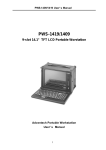
1
GP 7000F
M200, M200R, M400A, M400R, M600, M600R
Edition December 1999
Copyright and Trademarks
Copyright © Fujitsu Siemens Computers GmbH 1999.
All rights reserved.
Delivery subject to availability; right of technical modifications reserved.
All hardware and software names used are trademarks of their respective manufacturers.
1 Preface
This manual contains the operating instructions for the GranPower7000 (GP 7000F) system
from Fujitsu Siemens Computers. A chapter about the connection of Siemens specific devices precedes the actual operating instructions.
U42335-J-Z775-1-76
1
2 Console connections to GP 7000F
This chapter describes connections to the M200, M200R, M400A, M400R, M600 and
M600R models of the Fujitsu Siemens Computers GP 7000F system with a view to
attaching existing components of Siemens devices to Fujitsu equipment. Graphical or serial
consoles can be connected.
!
The GP 7000F systems do not support SIDATA
(installation by customer is not allowed).
2.1 Graphical console
It is preferable to connect graphical consoles.
GP 7000F
system
V.24 (A)
V.24 (B)
Teleservice
preferably
10/100 Mbit Eth
Monitor
PCI graphics
controller
D:GP70F-CC10
(option)
Keyboard
Keyboard/mouse
U42335-J-Z775-1-76
SUNAdapt
Mouse
(Keyboard with trackball
in the 19" rack)
3
Graphical console
Console connections to GP 7000F
The following technical requirements must be met in order to connect graphical consoles:
–
PCI graphics controller D:GP70F-CC10
The GP 7000F models can be made into a workstation or server with a graphical
console by means of a PCI graphics card featuring a frame buffer.
–
An RM keyboard and mouse can be connected via the D:GP70F-AN10 interface
converter. All models in the GP 7000F server family have a Sun-compatible
keyboard/mouse interface. The adapter converts the interface signals to allow the
keyboard and 3-button mouse featuring a PC-compatible interface to be connected
to the server.
P S / 2 M mouse
a u s
PS/2
P S / 2 T keyboard
a s ta tu r
PS/2
S U N - keyboard/
Sun
T a s t a t u r interface
/M a u s mouse
S c h n itts te lle
Keyboard/mouse adapter
–
Monitor (CRT or LCD)
–
Keyboard
–
Mouse
The same monitor, keyboard and mouse types have been released as for the Siemens
systems.
4
U42335-J-Z775-1-76
Console connections to GP 7000F
Serial console
2.2 Serial console
A converter is used here to convert the 25-pin connector of the GP 7000F system to the
usual 9-pin V.24/COM connector. This converter is preinstalled at the factory. A VT100 or
VT200 emulation must be available for a serial console to be used.
V 9-pin
.2 4 /C O M
9 p o lig
D 25-pin
s u b
2 5 p o lig
25/9-pin converter
U42335-J-Z775-1-76
5
Serial console
Console connections to GP 7000F
2.2.1 LAN console
A Solaris PC is connected as a LAN console via an RCA (Remote Communication Adapter)
attached to the V.24 console interface. Up to six servers can be attached to one RCA.
GP 7000F
system
V.24 (A)
RCA
LAN
console
V.24 (B)
10/100 Mbit Eth
Ethernet hub
Teleservice
Keyboard/mouse
6
U42335-J-Z775-1-76
Console connections to GP 7000F
Serial console
2.2.2 Standard PC with terminal emulation
a) Windows 98 or NT (with NetTerm, for instance, but not with HyperTerminal)
b) LINUX (with Minicom or Seyon)
c) Solaris (cu)
PC
(NT, Windows)
GP 7000F
system
V.24 (A)
V.24 (B)
Teleservice
preferably
10/100 Mbit Eth
Keyboard/mouse
U42335-J-Z775-1-76
7
Teleservice
Console connections to GP 7000F
2.2.3 TC20 or T100
Use of these terminals is intended as a migration solution only.
α console
GP 7000F
system
V.24 (A)
V.24 (B)
Teleservice
preferably
10/100 Mbit Eth
Keyboard/mouse
i
When operating with the LAN console, TC20 or T100 it is not possible to access the
Open Boot PROM using the BREAK signal.
2.3 Teleservice
The teleservice modem has to be connected via V.24 to the system board. The modem has
to be ordered separately owing to national variants.
If a LAN console is used, connection of the modem is to the LAN console PC. Thus one
teleservice port serves all connected servers.
8
U42335-J-Z775-1-76
P321-E102-02EN
USER'S MANUAL
IMPORTANT READING
FOR SAFE OPERATION
Handling of This Manual
This manual contains important information regarding the use and handling of this product. Read this manual
thoroughly. Pay special attention to the section "Important Warnings". Use the product according to the
instructions and information available in this manual.
FUJITSU makes every effort to prevent users and bystanders from being injured or from suffering from damages
to their property. Use the product according to this manual.
IMPORTANT NOTE TO USERS
READ CAREFULLY ALL THROUGHOUT THIS MANUAL BEFORE USING THE PRODUCT. INCORRECT
USE OF THE PRODUCT MAY CAUSE UNEXPECTED DAMAGE TO THE USERS OR BYSTANDERS.
While all efforts have been made to ensure the accuracy of all information in this manual, FUJITSU assumes no
liability to any party for any damage caused by errors or omissions or by statement of any kind in this manual, its
updates or supplements, whether such errors are omissions or statements resulting from negligence, accidents, or
any other cause. FUJITSU further assumes no liability for incidental or consequential damages arising from the
use of this manual. FUJITSU disclaims all warranties regarding the information contained herein, whether
expressed, implied, or statutory.
DO NOT MAKE MECHANICAL OR ELECTRICAL MODIFICATIONS TO THE EQUIPMENT. FUJITSU
LIMITED IS NOT RESPONSIBLE FOR REGULATORY COMPLIANCE OR SAFETY OF A MODIFIED
FUJITSU PRODUCT.
DO NOT REPAIR OR INSTALL THE EQUIPMENT BY USERS. IT SHOULD BE PERFORMED BY A
TRAINED SERVICE ENGINNER.
i
THIS PRODUCT IS NOT DESIGNED FOR USE IN ON-LINE CONTROL EQUIPMENT IN HAZARDOUS
ENVIRONMENTS SUCH AS OPERATION OF NUCLEAR FACILITIES, AIRCRAFT NAVIGATION OR
CONTROL, OR DIRECT LIFE SUPPORT MACHINES. HENCE, IF THESE PRODUCTS ARE USED IN
SUCH HAZARDOUS ENVIRONMENTS, FUJITSU LIMITED AND SUN MICROSYSTEMS, INC. DOES
NOT WARRANT THEM AT ALL.
FUJITSU reserves all the right to make changes to any products herein to improve reliability, function, or design,
without further notice and without obligation.
FCC Class A Notice
This equipment has been tested and found to comply with the limits for a Class A digital device,
pursuant to Part 15 of the FCC Rules. These limits are designed to provide reasonable protection
against harmful interference when the equipment is operated in a commercial environment. This
equipment generates, uses, and can radiate radio frequency energy and, if not installed and used in
accordance with the instruction manual, may cause harmful interference to radio communications.
Operation of this equipment in a residential area is likely to cause harmful interference in which
case the user will be required to correct the interference at his own expense.
DOC Class A Notice
This class A digital apparatus meets all requirements of the Canadian Interference-Causing
Equipment Regulations.
Cet appareil numerique de la class A respecte toutes les exigences du Reglement sur le material
brouiller du Canada.
Warning
This is a Class A product of Electromagnetic Interference (EMI) standard. In a domestic
environment this product may cause radio interference in which case the user may be required to
take adequate measures.
VCCI/FCC label
The VCCI/FCC labels for models 200R, 400R, and the Expansion file unit (GP7B7FLxx) are affixed in the
following locations:
VCCI / FCC label
ii
VCCI / FCC label
VCCI / FCC label
Laser Radiation Statement (EU)
Class 1 Laser Product
TRADEMARK ACKNOWLEDGMENTS
All rights reserved. This product and related documentation are protected by copyright and distributed under
licenses restricting its use, copying, distribution, and recompilation. No part of this product or related
documentation may be reproduced in any form by any means without prior written authorization of Fujitsu
Limited and its licensors, if any.
RESTRICTED RIGHTS LEGEND: Use, duplication, or disclosure by the United States Government is subject to
the restrictions set forth in DFARS 252.227-7013 (c) (1) (ii) and FAR 52.227-19.
The product described in this book may be protected by one or more U.S. patents, foreign patents, or pending
applications.
iii
TRADEMARKS
Fujitsu and the Fujitsu logo are trademarks of Fujitsu Limited.
SPARC64 is a registered trademark or trademark of SPARC International, Inc. in the United States
and other countries used under license by Fujitsu Ltd. Products bearing SPARC64 trademarks
comply with SPARC V9 architecture developed by SPARC International, Inc. Products bearing the
SPARC trademarks are based on an architecture originally developed by Sun Microsystems, Inc. "
Sun, the Sun logo, Sun Microsystems, Sun Microsystems Computer Corporation, the Sun
Microsystems Computer Corporation logo, SunSoft, the SunSoft logo, Solaris, Solaris PEX, SunOS,
SunLink, OpenWindows, Direct Xlib, SunSHIELD, NeWS, NeWSprint, SunInstall, DeskSet, ONC,
ONC+, OpenBoot, Online DiskSuite, NFS, JumpStart, AnswerBook, the AnswerBook logo,
SunDiag, ToolTalk, Sun PC, and Wabi are trademarks or registered trademarks of Sun
Microsystems, Inc., in the U.S. and certain other countries.
UNIX is a registered trademark in the United States and other countries, licensed exclusively
through X/Open Company Ltd.
All other product names mentioned herein are the trademarks of their respective owners.
THIS PUBLICATION IS PROVIDED "AS IS" WITHOUT WARRANTY OF ANY KIND, EITHER EXPRESS
OR IMPLIED, INCLUDING, BUT NOT LIMITED TO, THE IMPLIED WARRANTIES OR
MERCHANTABILITY, FITNESS FOR A PARTICULAR POURPOSE, OR NONINFRINGEMENT.
THIS PUBLICATION COULD INCLUDE TECHNICAL INACCURACIES OR TYPOGRAPHICAL ERRORS.
CHANGES ARE PERIODICALLY ADDED TO THE INFORMATION HEREIN; THESE CHANGES WILL BE
INCORPORATED IN NEW EDITIONS OF THE PUBLICATION. FUJITSU LIMITED MAY MAKE
IMPROVEMENTS AND/OR CHANGES IN THE PRODUCT(S) AND/OR THE PROGRAM(S) DESCRIBED
IN THIS PUBLICATION AT ANY TIME.
Documents produced by FUJITSU may contain technology controlled under the
Foreign Exchange and Foreign Trade Control Law of Japan. The document
which contains such technology should not be exported from Japan or
transferred to anyone other than residents of Japan without first obtaining
license from the Ministry of International Trade and Industry of Japan in
accordance with the above law.
Second Edition: November 1999
This manual may be best printed on A4 size. If it is printed on 8.5" ( 11" size, adjust your printer setting in advance.
The contents of this manual may be revised without prior notice.
The contents of this manual shall not be disclosed in any way or reproduced in any media without the express
written permission of Fujitsu Limited.
All Rights Reserved, Copyright (c) FUJITSU LIMITED 1999
iv
Preface
This manual explains the function, configuration, and operation of GP7000F. This manual is intended for the
experienced users who have a basic knowledge of computer systems.
The structure of this manual is as follows:
Introduction to Chapters
CHAPTER 1 Product Outline
Chapter 1 describes the distinctive features of GP7000F.
CHAPTER 2 M200 Main Cabinet
Chapter 2 explains the device configuration and operation of M200 Main Cabinet.
CHAPTER 3 M200R Main Cabinet
Chapter 3 explains the device configuration and operation of M200R Main Cabinet.
CHAPTER 4 M400A Main Cabinet
Chapter 4 explains the device configuration and operation of M400A Main Cabinet.
CHAPTER 5 M400R Main Cabinet
Chapter 5 explains the device configuration and operation of M400R Main Cabinet.
CHAPTER 6 M600 Main Cabinet
Chapter 6 explains the device configuration and operation of M600 Main Cabinet.
CHAPTER 7 M600R Main Cabinet
Chapter 7 explains the device configuration and operation of M600R Main Cabinet.
CHAPTER 8 Expansion Disk Cabinet
Chapter 8 describes the distinctive features of the GP7000F external disk cabinet.
CHAPTER 9 Expansion File Unit Type-2(GP7B7FLxx)
Chapter 9 describes the distinctive features of the GP7000F rack mount expansion disk unit.
CHAPTER 10 Expansion File Unit(GP7B7FU1xx)
Chapter 10 describes the distinctive features of the GP7000F rack mount expansion disk unit.
CHAPTER 11 Input-Output Units
Chapter 11 explains the specifications of Input-Output units.
v
CHAPTER 12 External Interface
Chapter 12 explains the external interface of the main cabinet such as UPS Control Interface,
RS232C Interface, and Centronics Interface.
CHAPTER 13 RCI Setting
Chapter 13 explains the description of RCI commands to be used for managing nodes.
CHAPTER 14 Troubleshooting
Chapter 14 will help the user isolate the cause of system failures, and provides suggested solutions.
Conventions for Warning Messages
A warning message consists of a signal and statements. The signal consists of a symbol and a signal word or just a
signal word.
The following are the signals and their meanings:
CAUTION
This indicates a hazardous situation could result in minor or moderate personal injury if the user
does not perform the procedure correctly. This signal also indicates that damage to the product or
other property, may occur if the user does not perform the procedure correctly.
IMPORTANT
This indicates information that could help the user use the product more efficiently.
In the text, the signal is centered, followed below by the indented message. A wider line space precedes and
follows the message to show where the message begins and ends. The following is an example:
(Example)
CAUTION
Data destruction: Do not press these buttons before installing the necessary
software package. Otherwise, data may be destroyed. Turn off the system in the
OBP prompt state if the software package is not installed.
Attention
Please forward any comments you may have regarding this manual.
To make this manual easier for users to understand, opinions from readers are needed. Please write your opinions
or requests on the "Comment Form" sheet at the back of this manual and forward it to the address provided on the
sheet.
vi
vii
Important Warnings
The following are cautions found in this manual. They have been compiled here with corresponding page
references.
CAUTION
A hazardous situation could result in minor or moderate personal injury if the
user does not perform the procedure correctly. Also, damage to the product or
other property may occur.
Task
viii
Warning
Normal Operation
Data destruction: Pressing the RESET switch while the
system is running may destroy data.
System Installation
Be sure to install software packages from "Basic Software
Extension" or "Enhanced Support Facility. Otherwise, above
switch functions or proper messages on LCD panel are not
guaranteed.
Terminal break command
If used improper commands at the ok prompt, the GP7000F
may be destroyed. If you need to used any other commands
except shown on this manual, you should well understand
the function and usage of the command before using it.
Power Off
Be sure to eject backup tape media and any diskettes before
power-off the system, if the media are installed. Other
wise, the data on the media may be destroyed.
Normal Operation
Except in an emergency, never turn off the AC switch or
disconnect the power cable wile the GP7000F main cabinet is
turned on. If you do, data in the disk drive may be
destroyed.
Task
Warning
System Installation
Install "Basic Software Extension" or "Enhanced Support
Facility"before operating the system. Without this package,
incorrect front panel operations and hardware errors may cause
the system to shutdown or destroy data.
Disk Expansion Unit
Installation
Be sure to replace the power supply fan when installing the
Disk Expansion Unit. Otherwise, the system will shutdown or
disk units will deteriorate due to a temperature rise in the
M200 main cabinet caused by insufficient cooling.
Disk Expansion Unit
Installation
If the installing location (slot) is not set or set
incorrectly, the disk drive may not be hot-swappable.
Data may be destroyed as a result of inadvertently replacing
the different disk drive. Be sure to set the installing
location (slot) correctly.
Also, while replacing or initializing NVRAM, set the
installing location again.
Normal Operation
Do not set the AC main line switch to OFF, not disconnect
the power cable or RCI cable while the GP7000F main cabinet
is powered on, unless absolutely necessary. Otherwise, the
data may be destroyed in the disk units.
Normal Operation
Do not set the AC main line switch to OFF, nor disconnect
the power cable or RCI cable while the GP7000F main cabinet
is powered on, unless absolutely necessary. Otherwise, the
data in the disk units may be destroyed.
Replacing Disk Drives
When replacing the disk unit,take the following precautions.
If these precautions are not observed, the disk unit or its
data may be destroyed.
Formatting Disk Drives
Carefully proceed formatting a disk drive. Once formatting
a disk drive, data on the disk never restored, if you don't
have backup files.
Handling Floppy Disks
Do not eject a floppy disk while the access LED is on, other
wise the floppy disk or the data on the diskette may be
destroyed.
For information on the handling method, see Table 11.2,
"Handling floppy disks."
Ejecting DAT cartridge
Data destruction: Do not press the eject switch during an
operation (when the tape LED is blinking). If the eject
switch is held down for about 5 seconds or pressed 3 times
within a 5 minutes period, the forced ejection function may
execute and the data being written may be destroyed.
Handling DAT cartridge
When using the data cartridge (DAT), take the following
precautions. If these precautions are not observed, the
DAT unit or its data may be destroyed.
Storing 8-mm cartridge
When using or storing the data cartridge, take the following
precautions. If these precautions are not taken, the data
on 8-mm tape may be destroyed.
Ejecting QIC cartridge
Data destruction: Do not press the eject switch during an
operation. The forced ejection function may operate and
data being written may be destroyed.
Storing QIC cartridge
When using or storing the data cartridge, take the following
precautions. If these precautions are not taken, the QIC
tape unit or its data may be destroyed.
ix
CONTENTS
CHAPTER 1
CHAPTER 2
Product Outline
1
1.1
Key Features
2
1.2
Operator Panel
1.3
External Interface
1.4
Console
1.5
Power On/Off
1.6
Installation of Basic Software Extension or Enhanced Support Facility
1.7
local-mac-address Property
: : : : : : : : : : : : : : : : : : : : : : : : : : : : : : : : : : : : :
: : : : : : : : : : : : : : : : : : : : : : : : : : : : : : : : : : : :
5
: : : : : : : : : : : : : : : : : : : : : : : : : : : : : : : : : :
8
: : : : : : : : : : : : : : : : : : : : : : : : : : : : : : : : : : : : : : :
10
: : : : : : : : : : : : : : : : : : : : : : : : : : : : : : : : : : : :
11
: : : : : : : :
12
: : : : : : : : : : : : : : : : : : : : : : : : : : : : : :
12
M200 Main Cabinet
13
2.1
Overview
14
2.2
Device Configuration
2.3
Systemboard
2.4
Disk Units
2.5
PCI Slots
2.6
Installation
: : : : : : : : : : : : : : : : : : : : : : : : : : : : : : : : : : : : : :
: : : : : : : : : : : : : : : : : : : : : : : : : : : : : : : : :
15
: : : : : : : : : : : : : : : : : : : : : : : : : : : : : : : : : : : : :
19
: : : : : : : : : : : : : : : : : : : : : : : : : : : : : : : : : : : : : :
21
: : : : : : : : : : : : : : : : : : : : : : : : : : : : : : : : : : : : : : :
23
: : : : : : : : : : : : : : : : : : : : : : : : : : : : : : : : : : : : : :
23
i
CHAPTER 3
CHAPTER 4
CHAPTER 5
CHAPTER 6
ii
M200R Main Cabinet
27
3.1
Overview
28
3.2
Device Configuration
3.3
Systemboard
3.4
Disk Units
3.5
PCI Slots
3.6
Installation
: : : : : : : : : : : : : : : : : : : : : : : : : : : : : : : : : : : : : :
: : : : : : : : : : : : : : : : : : : : : : : : : : : : : : : : :
29
: : : : : : : : : : : : : : : : : : : : : : : : : : : : : : : : : : : : :
32
: : : : : : : : : : : : : : : : : : : : : : : : : : : : : : : : : : : : : :
34
: : : : : : : : : : : : : : : : : : : : : : : : : : : : : : : : : : : : : : :
35
: : : : : : : : : : : : : : : : : : : : : : : : : : : : : : : : : : : : : :
36
M400A Main Cabinet
41
4.1
Overview
42
4.2
Device Configuration
4.3
Systemboard
4.4
Disk Units
4.5
PCI Slots
4.6
Installation
: : : : : : : : : : : : : : : : : : : : : : : : : : : : : : : : : : : : : :
: : : : : : : : : : : : : : : : : : : : : : : : : : : : : : : : :
43
: : : : : : : : : : : : : : : : : : : : : : : : : : : : : : : : : : : : :
46
: : : : : : : : : : : : : : : : : : : : : : : : : : : : : : : : : : : : : :
48
: : : : : : : : : : : : : : : : : : : : : : : : : : : : : : : : : : : : : : :
49
: : : : : : : : : : : : : : : : : : : : : : : : : : : : : : : : : : : : : :
50
M400R Main Cabinet
53
5.1
Overview
54
5.2
Device Configuration
5.3
Systemboard
5.4
Disk Units
5.5
PCI Slots
5.6
Installation
: : : : : : : : : : : : : : : : : : : : : : : : : : : : : : : : : : : : : :
: : : : : : : : : : : : : : : : : : : : : : : : : : : : : : : : :
55
: : : : : : : : : : : : : : : : : : : : : : : : : : : : : : : : : : : : :
58
: : : : : : : : : : : : : : : : : : : : : : : : : : : : : : : : : : : : : :
60
: : : : : : : : : : : : : : : : : : : : : : : : : : : : : : : : : : : : : : :
61
: : : : : : : : : : : : : : : : : : : : : : : : : : : : : : : : : : : : : :
62
M600 Main Cabinet
67
6.1
Overview
68
6.2
Device Configuration
: : : : : : : : : : : : : : : : : : : : : : : : : : : : : : : : : : : : : :
: : : : : : : : : : : : : : : : : : : : : : : : : : : : : : : : :
69
CONTENTS
CHAPTER 7
CHAPTER 8
CHAPTER 9
CHAPTER 10
6.3
Systemboard
: : : : : : : : : : : : : : : : : : : : : : : : : : : : : : : : : : : : :
72
6.4
Disk Units
: : : : : : : : : : : : : : : : : : : : : : : : : : : : : : : : : : : : : :
75
6.5
PCI Slots
: : : : : : : : : : : : : : : : : : : : : : : : : : : : : : : : : : : : : : :
75
6.6
Installation
: : : : : : : : : : : : : : : : : : : : : : : : : : : : : : : : : : : : : :
77
M600R Main Cabinet
81
7.1
Overview
82
7.2
Device Configuration
7.3
Systemboard
7.4
Disk Units
7.5
PCI Slots
7.6
Installation
: : : : : : : : : : : : : : : : : : : : : : : : : : : : : : : : : : : : : :
: : : : : : : : : : : : : : : : : : : : : : : : : : : : : : : : :
83
: : : : : : : : : : : : : : : : : : : : : : : : : : : : : : : : : : : : :
86
: : : : : : : : : : : : : : : : : : : : : : : : : : : : : : : : : : : : : :
88
: : : : : : : : : : : : : : : : : : : : : : : : : : : : : : : : : : : : : : :
89
: : : : : : : : : : : : : : : : : : : : : : : : : : : : : : : : : : : : : :
91
Expansion Disk Cabinet
95
8.1
Product Outline
96
8.2
Device Configuration
8.3
Hot System Replacement
8.4
Installation
: : : : : : : : : : : : : : : : : : : : : : : : : : : : : : : : : : :
: : : : : : : : : : : : : : : : : : : : : : : : : : : : : : : : :
97
: : : : : : : : : : : : : : : : : : : : : : : : : : : : : : :
101
: : : : : : : : : : : : : : : : : : : : : : : : : : : : : : : : : : : : : :
102
Expansion File Unit Type-2 (GP7B7FLxx)
105
9.1
Product Outline
106
9.2
Device Configuration
9.3
Hot System Replacement
9.4
Installation
: : : : : : : : : : : : : : : : : : : : : : : : : : : : : : : : : : :
: : : : : : : : : : : : : : : : : : : : : : : : : : : : : : : : :
107
: : : : : : : : : : : : : : : : : : : : : : : : : : : : : : :
109
: : : : : : : : : : : : : : : : : : : : : : : : : : : : : : : : : : : : : :
110
Expansion File Unit (GP7B7FU1xx)
113
10.1
114
Product Outline
: : : : : : : : : : : : : : : : : : : : : : : : : : : : : : : : : : :
iii
CHAPTER 11
CHAPTER 12
CHAPTER 13
CHAPTER 14
iv
10.2
Device Configuration
10.3
Hot System Replacement
10.4
Installation
: : : : : : : : : : : : : : : : : : : : : : : : : : : : : : : : :
115
: : : : : : : : : : : : : : : : : : : : : : : : : : : : : : :
117
: : : : : : : : : : : : : : : : : : : : : : : : : : : : : : : : : : : : : :
118
Input-Output Units
121
11.1
Disk Units
122
11.2
Floppy Disk Units
11.3
CD-ROM Unit
11.4
: : : : : : : : : : : : : : : : : : : : : : : : : : : : : : : : : : : : : :
: : : : : : : : : : : : : : : : : : : : : : : : : : : : : : : : : :
123
: : : : : : : : : : : : : : : : : : : : : : : : : : : : : : : : : : : :
126
Tape Unit
: : : : : : : : : : : : : : : : : : : : : : : : : : : : : : : : : : : : : :
128
11.5
DAT Unit
: : : : : : : : : : : : : : : : : : : : : : : : : : : : : : : : : : : : : :
129
11.6
8-mm Tape Unit
11.7
QIC Tape Unit
: : : : : : : : : : : : : : : : : : : : : : : : : : : : : : : : : : :
135
: : : : : : : : : : : : : : : : : : : : : : : : : : : : : : : : : : : :
140
External Interfaces
12.1
UPS Control Interface
12.2
RS232C Interface
12.3
Parallel Interface
145
: : : : : : : : : : : : : : : : : : : : : : : : : : : : : : : :
146
: : : : : : : : : : : : : : : : : : : : : : : : : : : : : : : : : :
148
: : : : : : : : : : : : : : : : : : : : : : : : : : : : : : : : : : :
151
RCI Setting
153
13.1
Overview
13.2
RCI Commands
13.3
Liquid Crystal Display (LCD) Specifications
: : : : : : : : : : : : : : : : : : : : : : : : : : : : : : : : : : : : : :
: : : : : : : : : : : : : : : : : : : : : : : : : : : : : : : : : : :
: : : : : : : : : : : : : : : : : : : : :
154
154
155
Troubleshooting
157
14.1
Overview
158
14.2
Commands at the ok prompt
14.3
Initial Diagnosis Sequence
: : : : : : : : : : : : : : : : : : : : : : : : : : : : : : : : : : : : : :
: : : : : : : : : : : : : : : : : : : : : : : : : : : : :
158
: : : : : : : : : : : : : : : : : : : : : : : : : : : : : :
159
CONTENTS
14.4
SCF Error Messages
: : : : : : : : : : : : : : : : : : : : : : : : : : : : : : : : :
160
v
ILLUSTRATIONS
Figure 1.1
Operator Panel (M200, M600)
Figure 1.2
Operator Panel (M200R, M400A, M400R, M600R)
Figure 2.1
: : : : : : : : : : : : : : : : : : : : : : : : : : : : : :
5
: : : : : : : : : : : : : : : : : : :
5
Front View of M200 Main Cabinet
: : : : : : : : : : : : : : : : : : : : : : : : : : : :
14
Figure 2.2
Open View of M200 Main Cabinet
: : : : : : : : : : : : : : : : : : : : : : : : : : : :
16
Figure 2.3
Rear View of M200 Main Cabinet
: : : : : : : : : : : : : : : : : : : : : : : : : : : :
18
Figure 2.4
Systemboard Layout of M200
: : : : : : : : : : : : : : : : : : : : : : : : : : : : : :
19
Figure 2.5
Disk Drive Bays of M200 Main Cabinet
Figure 3.1
: : : : : : : : : : : : : : : : : : : : : : : : :
21
Front View of M200R Main Cabinet
: : : : : : : : : : : : : : : : : : : : : : : : : : :
28
Figure 3.2
Open View of M200R Main Cabinet
: : : : : : : : : : : : : : : : : : : : : : : : : : :
29
Figure 3.3
Rear View of M200R Main Cabinet
: : : : : : : : : : : : : : : : : : : : : : : : : : :
31
Figure 3.4
Systemboard Layout of M200R
: : : : : : : : : : : : : : : : : : : : : : : : : : : : :
32
Figure 4.1
Front View of M400A Main Cabinet
: : : : : : : : : : : : : : : : : : : : : : : : : : :
42
Figure 4.2
Open View of M400A Main Cabinet
: : : : : : : : : : : : : : : : : : : : : : : : : : :
43
Figure 4.3
Rear View of M400A Main Cabinet
: : : : : : : : : : : : : : : : : : : : : : : : : : :
45
Figure 4.4
Systemboard Layout of M400A
: : : : : : : : : : : : : : : : : : : : : : : : : : : : :
46
Figure 5.1
Front View of M400R Main Cabinet
: : : : : : : : : : : : : : : : : : : : : : : : : : :
54
Figure 5.2
Open View of M400R Main Cabinet
: : : : : : : : : : : : : : : : : : : : : : : : : : :
55
Figure 5.3
Rear View of M400R Main Cabinet
: : : : : : : : : : : : : : : : : : : : : : : : : : :
57
Figure 5.4
Systemboard Layout of M400R
: : : : : : : : : : : : : : : : : : : : : : : : : : : : :
58
Figure 6.1
Front View of M600 Main Cabinet
: : : : : : : : : : : : : : : : : : : : : : : : : : : :
68
vii
viii
Figure 6.2
Open View of M600 Main Cabinet
: : : : : : : : : : : : : : : : : : : : : : : : : : : :
69
Figure 6.3
Rear View of M600 Main Cabinet
: : : : : : : : : : : : : : : : : : : : : : : : : : : :
71
Figure 6.4
Systemboard Layout of M600
: : : : : : : : : : : : : : : : : : : : : : : : : : : : : :
72
Figure 6.5
PCI IO Board Layout of M600
: : : : : : : : : : : : : : : : : : : : : : : : : : : : : :
75
Figure 7.1
Front View of M600R Main Cabinet
: : : : : : : : : : : : : : : : : : : : : : : : : : :
82
Figure 7.2
Open View of M600R Main Cabinet
: : : : : : : : : : : : : : : : : : : : : : : : : : :
83
Figure 7.3
Front View of M600R Main Cabinet (remove Front cover)
Figure 7.4
Rear View of M600R Main Cabinet
Figure 7.5
Systemboard Layout of M600R
Figure 7.6
: : : : : : : : : : : : : : : :
84
: : : : : : : : : : : : : : : : : : : : : : : : : : :
85
: : : : : : : : : : : : : : : : : : : : : : : : : : : : :
86
PCIBPR Board Layout of M600R
: : : : : : : : : : : : : : : : : : : : : : : : : : : :
89
Figure 7.7
PCIRSR Board Layout of M600R
: : : : : : : : : : : : : : : : : : : : : : : : : : : :
89
Figure 8.1
Front View of Expansion Disk Cabinet
: : : : : : : : : : : : : : : : : : : : : : : : : :
97
Figure 8.2
Drive Bays of Expansion Disk Cabinet
: : : : : : : : : : : : : : : : : : : : : : : : : :
98
Figure 8.3
Rear View of Expansion Disk Cabinet
: : : : : : : : : : : : : : : : : : : : : : : : : :
100
Figure 9.1
Front View of Expansion File Unit Type-2
: : : : : : : : : : : : : : : : : : : : : : : :
106
Figure 9.2
Drive Bays of Expansion File Unit Type-2
: : : : : : : : : : : : : : : : : : : : : : : :
107
Figure 9.3
Drive Bays of Expansion File Unit Type-2
: : : : : : : : : : : : : : : : : : : : : : : :
108
Figure 9.4
Rear View of Expansion File Unit Type-2
: : : : : : : : : : : : : : : : : : : : : : : :
108
Figure 10.1
Front View of Expansion File Unit
: : : : : : : : : : : : : : : : : : : : : : : : : : : :
114
Figure 10.2
Drive Bays of Expansion File Unit
: : : : : : : : : : : : : : : : : : : : : : : : : : : :
115
Figure 10.3
Rear View of Expansion File Unit
: : : : : : : : : : : : : : : : : : : : : : : : : : : :
116
Figure 11.1
Floppy Disk Unit Front Panel
: : : : : : : : : : : : : : : : : : : : : : : : : : : : : :
123
Figure 11.2
Inserting Floppy Disks
: : : : : : : : : : : : : : : : : : : : : : : : : : : : : : : : : :
124
Figure 11.3
CD-ROM Unit Front Panel
Figure 11.4
Mark on CD-ROM Disk
Figure 11.5
DAT Unit Front Panel
Figure 11.6
DDS Logos
Figure 11.7
DDS Media Recognition System Logo
Figure 11.8
Inserting a Data Cartridge in The DAT Unit :
Figure 11.9
DAT Data Cartridge Write-protection Tab
Figure 11.10
8-mm Tape Unit Front Panel
Figure 11.11
8-mm Tape Data Cartridge
Figure 11.12
Cleaning Cartridge of The 8-mm Tape Unit
: : : : : : : : : : : : : : : : : : : : : : : :
139
Figure 11.13
Cleaning Cartridge of The 8-mm Tape Unit
: : : : : : : : : : : : : : : : : : : : : : : :
139
Figure 11.14
QIC Tape Drive Front Panel
: : : : : : : : : : : : : : : : : : : : : : : : : : : : : : :
140
Figure 11.15
QIC Data Cartridge :
: : : : : : : : : : : : : : : : : : : : : : : : : : : : : : : : : : :
142
: : : : : : : : : : : : : : : : : : : : : : : : : : : : : : : :
126
: : : : : : : : : : : : : : : : : : : : : : : : : : : : : : : : :
127
: : : : : : : : : : : : : : : : : : : : : : : : : : : : : : : : : :
130
: : : : : : : : : : : : : : : : : : : : : : : : : : : : : : : : : : : : : : :
132
: : : : : : : : : : : : : : : : : : : : : : : : : :
132
: : : : : : : : : : : : : : : : : : : : : : :
132
: : : : : : : : : : : : : : : : : : : : : : : :
133
: : : : : : : : : : : : : : : : : : : : : : : : : : : : : : :
136
: : : : : : : : : : : : : : : : : : : : : : : : : : : : : : : :
137
ILLUSTRATIONS
Figure 12.1
Signal Configuration
Figure 12.2
Configuration of Signal Line when Connecting DCE Device(Example)
Figure 12.3
Configuration of Signal Line when Connecting DTE Line(Example)
Figure 14.1
Power-on Sequence
: : : : : : : : : : : : : : : : : : : : : : : : : : : : : : : : : : :
147
: : : : : : : : : :
150
: : : : : : : : : : :
150
: : : : : : : : : : : : : : : : : : : : : : : : : : : : : : : : : : :
159
ix
TABLES
x
Table 1.1
Data Protection for Components and Interfaces
: : : : : : : : : : : : : : : : : : : : : :
3
Table 1.2
POWER LED
: : : : : : : : : : : : : : : : : : : : : : : : : : : : : : : : : : : : : :
6
Table 1.3
CHECK LED
: : : : : : : : : : : : : : : : : : : : : : : : : : : : : : : : : : : : : :
6
Table 1.4
MODE Switch Settings :
: : : : : : : : : : : : : : : : : : : : : : : : : : : : : : : : :
7
Table 1.5
Connectors and Switches
: : : : : : : : : : : : : : : : : : : : : : : : : : : : : : : : :
9
Table 1.6
Connectors and Switches for Maintenance
Table 2.1
Fans
Table 2.2
PCI Slot Specifications
Table 2.3
Installation Specifications of M200 Main Cabinet (1)
: : : : : : : : : : : : : : : : : : :
24
Table 2.4
Installation Specifications of M200 Main Cabinet (2)
: : : : : : : : : : : : : : : : : : :
25
Table 3.1
Fans
: : : : : : : : : : : : : : : : : : : : : : : : : : : : : : : : : : : : : : : : : : :
30
Table 3.2
Power Supply Units
Table 3.3
PCI Slot Specifications
Table 3.4
Mounting Combination for Expansion Rack
Table 3.5
: : : : : : : : : : : : : : : : : : : : : : : :
9
: : : : : : : : : : : : : : : : : : : : : : : : : : : : : : : : : : : : : : : : : : :
17
: : : : : : : : : : : : : : : : : : : : : : : : : : : : : : : : : :
: : : : : : : : : : : : : : : : : : : : : : : : : : : : : : : : : : :
: : : : : : : : : : : : : : : : : : : : : : : : : : : : : : : : : :
23
30
35
: : : : : : : : : : : : : : : : : : : : : : :
37
Installation Specifications of M200R (1)
: : : : : : : : : : : : : : : : : : : : : : : : :
38
Table 3.6
Installation Specifications of M200R (2)
: : : : : : : : : : : : : : : : : : : : : : : : :
39
Table 4.1
Fans
: : : : : : : : : : : : : : : : : : : : : : : : : : : : : : : : : : : : : : : : : : :
44
Table 4.2
Power Supply Units
Table 4.3
PCI Slot Specifications
Table 4.4
Installation Specifications of M400A Main Cabinet (1)
: : : : : : : : : : : : : : : : : :
51
Table 4.5
Installation Specifications of M400A Main Cabinet (2)
: : : : : : : : : : : : : : : : : :
52
: : : : : : : : : : : : : : : : : : : : : : : : : : : : : : : : : : :
: : : : : : : : : : : : : : : : : : : : : : : : : : : : : : : : : :
44
49
TABLES
Table 5.1
Fans
Table 5.2
Power Supply Units
Table 5.3
PCI Slot Specifications
Table 5.4
Mounting Combination for Expansion Rack
Table 5.5
Installation Specifications of M400R
Table 5.6
Installation Specifications of M400R (2)
Table 6.1
Fans
Table 6.2
Power Supply Units
Table 6.3
CPU Module Configurations
Table 6.4
PCI Slot Specifications
Table 6.5
Installation Specifications of M600 Main Cabinet (1)
: : : : : : : : : : : : : : : : : : :
78
Table 6.6
Installation Specifications of M600 Main Cabinet (2)
: : : : : : : : : : : : : : : : : : :
79
Table 7.1
Fans
: : : : : : : : : : : : : : : : : : : : : : : : : : : : : : : : : : : : : : : : : : :
84
Table 7.2
Power Supply Units
Table 7.3
CPU Module Configurations
Table 7.4
PCI Slot Specifications
Table 7.5
Mounting Combination for Expansion Rack
Table 7.6
Installation Specifications of M600R
Table 7.7
Installation Specifications of M600R (2)
Table 8.1
CHECK LED Status
Table 8.2
LEDs
Table 8.3
Expansion Disk Cabinet Installation Specifications (1)
Table 8.4
Installation Specifications of Expansion Disk Cabinet (2)
Table 9.1
CHECK LED Status
Table 9.2
LEDs
Table 9.3
Mounting Combination for Expansion Rack
Table 9.4
Installation Specifications of Expansion File Unit Type-2
Table 10.1
CHECK LED Status
Table 10.2
LEDs
Table 10.3
Mounting Combination for Expansion Rack
Table 10.4
Installation Specifications of Expansion File Unit
Table 11.1
Disk Units LEDs
Table 11.2
Handling Floppy Disks
Table 11.3
LED Displays on The DAT Unit
Table 11.4
DAT Cartridge Capacity
: : : : : : : : : : : : : : : : : : : : : : : : : : : : : : : : : : : : : : : : : : :
: : : : : : : : : : : : : : : : : : : : : : : : : : : : : : : : : : :
: : : : : : : : : : : : : : : : : : : : : : : : : : : : : : : : : :
56
56
61
: : : : : : : : : : : : : : : : : : : : : : :
63
: : : : : : : : : : : : : : : : : : : : : : : : : : :
64
: : : : : : : : : : : : : : : : : : : : : : : : :
65
: : : : : : : : : : : : : : : : : : : : : : : : : : : : : : : : : : : : : : : : : : :
70
: : : : : : : : : : : : : : : : : : : : : : : : : : : : : : : : : : :
71
: : : : : : : : : : : : : : : : : : : : : : : : : : : : : : :
73
: : : : : : : : : : : : : : : : : : : : : : : : : : : : : : : : : :
76
: : : : : : : : : : : : : : : : : : : : : : : : : : : : : : : : : : :
85
: : : : : : : : : : : : : : : : : : : : : : : : : : : : : : :
87
: : : : : : : : : : : : : : : : : : : : : : : : : : : : : : : : : :
90
: : : : : : : : : : : : : : : : : : : : : : :
92
: : : : : : : : : : : : : : : : : : : : : : : : : : :
93
: : : : : : : : : : : : : : : : : : : : : : : : :
94
: : : : : : : : : : : : : : : : : : : : : : : : : : : : : : : : : : :
99
: : : : : : : : : : : : : : : : : : : : : : : : : : : : : : : : : : : : : : : : : :
101
: : : : : : : : : : : : : : : : : :
103
: : : : : : : : : : : : : : : : :
104
: : : : : : : : : : : : : : : : : : : : : : : : : : : : : : : : : : :
108
: : : : : : : : : : : : : : : : : : : : : : : : : : : : : : : : : : : : : : : : : :
109
: : : : : : : : : : : : : : : : : : : : : : :
111
: : : : : : : : : : : : : : : : :
112
: : : : : : : : : : : : : : : : : : : : : : : : : : : : : : : : : : :
116
: : : : : : : : : : : : : : : : : : : : : : : : : : : : : : : : : : : : : : : : : :
117
: : : : : : : : : : : : : : : : : : : : : : :
119
: : : : : : : : : : : : : : : : : : : : :
120
: : : : : : : : : : : : : : : : : : : : : : : : : : : : : : : : : : : : :
122
: : : : : : : : : : : : : : : : : : : : : : : : : : : : : : : : : :
125
: : : : : : : : : : : : : : : : : : : : : : : : : : : : :
131
: : : : : : : : : : : : : : : : : : : : : : : : : : : : : : : : :
131
xi
xii
Table 11.5
8-mm Tape Cartridge Capacity
: : : : : : : : : : : : : : : : : : : : : : : : : : : : : :
136
Table 11.6
QIC Tape Cartridge Capacity
: : : : : : : : : : : : : : : : : : : : : : : : : : : : : : :
141
Table 12.1
Definitions of UPS Signal Lines
Table 12.2
: : : : : : : : : : : : : : : : : : : : : : : : : : : : :
146
Input Circuits
: : : : : : : : : : : : : : : : : : : : : : : : : : : : : : : : : : : : : :
147
Table 12.3
Output Circuits
: : : : : : : : : : : : : : : : : : : : : : : : : : : : : : : : : : : : : :
147
Table 12.4
Electrical Rating Specifications
Table 12.5
Definitions of Signal Lines
Table 12.6
IEEE1284-A Connector Terminal Distribution
Table 12.7
IEEE1284-A Connector Terminal Distribution (Continued)
Table 14.1
The ’show-post-results’ Command
Table 14.2
OBP Error Messages
Table 14.3
Power Unit Configuration Error Messages
: : : : : : : : : : : : : : : : : : : : : : : :
161
Table 14.4
Power/Fan/Environmental Error Messages
: : : : : : : : : : : : : : : : : : : : : : : :
162
Table 14.5
Processor Monitoring Error Messages
: : : : : : : : : : : : : : : : : : : : : : : : : :
163
Table 14.6
Lithium Battery Error Messages
: : : : : : : : : : : : : : : : : : : : : : : : : : : : :
163
Table 14.7
Other Error Messages
: : : : : : : : : : : : : : : : : : : : : : : : : : : : : : : : : :
164
: : : : : : : : : : : : : : : : : : : : : : : : : : : : : :
148
: : : : : : : : : : : : : : : : : : : : : : : : : : : : : : : :
149
: : : : : : : : : : : : : : : : : : : : : :
151
: : : : : : : : : : : : : : : :
152
: : : : : : : : : : : : : : : : : : : : : : : : : : : :
158
: : : : : : : : : : : : : : : : : : : : : : : : : : : : : : : : : : :
160
1
CHAPTER 1
Product Outline
CONTENTS
1.1
1.2
1.3
1.4
1.5
1.6
1.7
Key Features . . . . . . . . . . . . . . . . . . . . . . . . . . . . . . . . . . . . . . . . . . . . . . . . . . . . . . . . . . . . . . . . . . . . . . . . . . . . . . . . . . . .
Operator Panel . . . . . . . . . . . . . . . . . . . . . . . . . . . . . . . . . . . . . . . . . . . . . . . . . . . . . . . . . . . . . . . . . . . . . . . . . . . . . . . . .
External Interface . . . . . . . . . . . . . . . . . . . . . . . . . . . . . . . . . . . . . . . . . . . . . . . . . . . . . . . . . . . . . . . . . . . . . . . . . . . . . .
Console
....................................................................................
Power On/Off . . . . . . . . . . . . . . . . . . . . . . . . . . . . . . . . . . . . . . . . . . . . . . . . . . . . . . . . . . . . . . . . . . . . . . . . . . . . . . . . .
Installation of Basic Software Extension or Enhanced Support Facility . . . . . . . . . . . . . . . . . . . . . . . . . . .
local-mac-address Property . . . . . . . . . . . . . . . . . . . . . . . . . . . . . . . . . . . . . . . . . . . . . . . . . . . . . . . . . . . . . . . . . .
2
5
8
10
11
12
12
1
CHAPTER 1 Product Outline
1.1 Key Features
The GP7000F is SMP (Symmetric Multi-Processor) servers with 64-bit SPARC64 GP processors. Each model in
the group has high-performance 64-bit processors, high-speed I/O interfaces and enhanced reliability, availability,
and serviceability (RAS) features. The crossbar configuration is used as the system architecture of the GP7000F,
and the performance of the multi-processor configuration has been improved almost linear scalability.
The GP7000F, which has excellent scalability and reliability, is an ideal server for not only group or department
servers but also for mission-critical enterprise servers.
IMPORTANT
The availability of these products depends on the Sales and Support Companies. Please contact these
companies.
High-performance SPARC64 GP Processor
The SPARC64 GP is a high performance processor which has an out-of-order execution engine.
The SPARC64 GP supports large size external cache of 2MB/4MB/8MB per processor as well
as 64KB(instruction)+64KB(Data) on-chip cache.
Error Correcting Code (ECC) is used for both on-chip and external cache.
High-performance Multi-Processor Platform
Symmetric Multiprocessing (SMP) architecture
The memory system has a high bandwidth, up to 8-way interleaving, and which enables fast
access.
A packet-based bus protocol, to enable a throughput of 1.3 to 1.6 GB/s per processor, is
implemented.
A crossbar configuration, which is based on a packet bus, enables high-level parallel operations
of processors and memory modules, I/O and memory modules, and data transfer among
processors. And, the system delivers scalable performance by installing additional processors
and I/Os.
– The crossbar switch enables parallel operations of several processors and I/Os.
– The performance of the single bus is improved by expanding the bus width and high
frequency operation.
– The efficiency of bus usage is drastically improved by bus control in the packet exchange
system.
High-performance EDO DRAM (Extended Data Out DRAM) is used on the platform for the
memory expansion.(M200, M600)
High-performance SDRAM (Synchronous DRAM) is used on the platform for the memory
expansion.(M200R, M400A, M400R, M600R)
2
1.1 Key Features
High-speed I/O interface
One built-in 40 MB/s UltraSCSI Single-Ended interface for internal devices.
One built-in 100BASE-TX interface (10/100 Mbps, auto-sensing).
The GP7000F has some 64-bits PCI (Peripheral Component Interconnect) buses.
Additional interfaces, such as 100BASE-TX, FDDI, ATM, can be provided by installing PCI
cards. Both short and long size PCI cards can be installed. (*1)
*1)
The maximum length of the cards that can be installed in PCI slots #8 to #12 of the
M600R Main cabinet is 19.4cm.
High-performance, Large-capacity File Devices
Up to 22, 7200rpm or 10000rpm, UltraSCSI disk drives can be built in. Note that the number of
drives that can be installed depends on each model.
The disk drives can be hot-swappable
One CD-ROM drive unit is provided as standard.
One tape drive can be built in as optional.
Reliability, Availability, and Serviceability (RAS) features
Error Correction Code (ECC) is implemented for on-chip cache, external cache, memory
module and data paths. The data for the I/O data path(PCI) is protected by parity.
Table 1.1 Data Protection for Components and Interfaces
Components and interfaces
Data protection method
Processor (on-chip & external cache)
By ECC (corrects 1 bit and detects 2 bit)
Memory
By ECC (corrects 1 bit and detects 2 bit)
Data path
By ECC (corrects 1 bit and detects 2 bit)
Address path
By parity
I/O bus (PCI)
By parity
Processor operation
Operation monitoring by an independent
processor
Built-in basic SCSI, LAN, parallel
By parity, IP check sum
Note:
The RS232C interface and a floppy disk on a standard configuration are not
protected by parity.
Power-on diagnostics are executed on the system components, such as processors, memory
modules and so on, during initial power-on or reset of the system.
Automatic System Reconfiguration (ASR) isolates faulty hardware components immediately
after detecting it. The ASR function isolates not only faulty components detected during initial
power-on but also those detected while the system is running. However, the ASR function
cannot restart the system if errors are detected in the resources required for booting up the
system, or in the basic components of the system.
3
CHAPTER 1 Product Outline
A SCF (System Control Facility), which has an integrated service processor, monitors the
operation of SPARC64 GP processors, and reports erroneous events such as environmental
monitoring explained below. With a GUI-based intelligent monitoring and reporting tool,
which is provided in "Basic Software Extension" or "Enhanced Support Facility",
administration and management of GP7000F is easy and less time consuming.
The SCF monitors environmental temperature, powering and cooling conditions. This function
prevents the system from environmental condition that can cause error or damages to the
system.
– Monitoring Environmental Temperature ; The guaranteed operating temperature of the
system ranges from 5 to 35 degrees Celsius (41 to 95 degrees Fahrenheit). A warning
message is displayed at about 35 degrees Celsius (95 degrees Fahrenheit). If the
temperature reaches about 40 degrees Celsius (104 degrees Fahrenheit), the system is shut
down automatically.
– Monitoring Powers ; The power supplies are always monitored, and a message is displayed
on the LCD panel, if power supply failure is detected. When the system doesn’t have a
redundant power supply, the system will be powered off immediately. Besides it, the
integrated service processor monitors and controls DC-DC converter which provides
power to the processor modules.
– Monitoring Fans ; Several fans are installed inside the GP7000F main cabinet. If one of the
fans breaks down, a warning message which indicates the defective fan is displayed on the
LCD panel. And, if the fans cannot provide enough cooling, the system is shut down
automatically.
RCI (Remote Cabinet Interface) makes power cycle control of expansion I/O unit, such as
Expansion Disk Unit and Expansion File Unit, which has the RCI interface.
Status of LEDs and messages on LCD panel of GP7000F main cabinet as well as console
messages make trouble shooting easy and less time consuming.
All internal disk drives are hot-swappable, and these drives can be mirrored for higher data
availability. In addition, redundant power supplies and fans are supported for higher availability.
The front cover/panel has a lock key to prevent unauthorized access to the internal I/O devices
as well as front panel switches.
4
1.2 Operator Panel
1.2 Operator Panel
The operator panel has a set of status LEDs, switches, and a LCD panel. The switches as well as built-in I/O
device are covered with a panel cover that can be locked with a key. It prevents incorrect operations and ensures
security for the internal I/O device as well as the switches.
RESET switch REQUEST switch
POWER switch
LCD panel
REQUEST
POWER
RESET
CHECK
POWER
AUTO
MANUAL
SECURE
POWER LED( green )
MODE switch
CHECK LED( amber )
Figure 1.1 Operator Panel (M200, M600)
CHECK LED (amber)
POWER LED (green)
LCD panel
POWER switch
CHECK POWER
POWER
REQUEST RESET
AUTO
MANUAL
REQUEST switch
SECURE
MODE switch
RESET swich
Figure 1.2 Operator Panel (M200R, M400A, M400R, M600R)
5
CHAPTER 1 Product Outline
LED (CHECK LED/POWER LED)
The POWER LED indicates whether the system is turned on while the CHECK LED indicates
system operation by lighting up or blinking.
Table 1.2 POWER LED
Descriptions
Status
ON
The power is on
OFF
The power is off
The user and system administrator can recognize the system operation status from the CHECK LED
and messages that appear on the LCD panel.
Table 1.3 CHECK LED
Status
Descriptions
ON
The system is turned on, but the processors are not operating.
Blinking
(quickly)
System down.
Blinking
(slowly)
There are faulty components in the system. (The system is still
operating)
OFF
The system is not turned on or it is operating normally
If the system administrator shuts down the system (when the AC main line switch is on) while there
are degraded-mode components remaining in the system, the CHECK LED will continue to blink
slowly to remind the system administrator there are faulty components to be diagnosed. Possible
causes of a CHECK LED alarm are: errors in temperature monitoring, related components (such as
the power supplies and fans) or degraded-mode components (such as processors and memory
modules, etc.).
When the system is turned on, the CHECK LED lights up briefly. However, this is not an error
unless the CHECK LED remains light up for more than three seconds, or begins to blink.
LCD
The LCD panel can display 2 rows of 16 digits. The messages displayed on it are status or results of
the power-on diagnostics, and environmental events such as over temperature, etc. Therefore, when
an error occurs, the user or system administrator can recognize the state of the hardware system
easily by checking the messages displayed on the LCD panel as well as console messages.
Error messages remain on the LCD panel until the error is corrected. There is only one LCD panel,
therefore, it displays messages in turn when there are several errors. Note that error events are
corrected even though their message displayed on the panel is overwritten by messages of other
events. However, since the initial diagnostics is allowed to report only one event, the next message
of another event will be displayed on the panel after repaired a reported event.
Messages are erased from the panel when:
an error event is corrected.
the power of the main cabinet is cycled
the AC main line switch is turned off, or
the RESET switch is pressed (partial messages are erased).
When an error or an abnormal state occurs, record the messages displayed on the LCD panel and
status of the CHECK LED. Then, contact the system administrator or service engineers. See 14
"Troubleshooting" for more information regarding the messages displayed on the LCD panel.
6
1.2 Operator Panel
Switches There are 4 switches on the operator panel, as below.
POWER switch
The user can turn on and off the system by pressing this switch. The POWER switch
operation is managed by the setting of the MODE switch as well as software setting
with "scftool". By pressing the POWER switch while the system is running, the
system will be powered off after graceful shutdown. Refer to the user’s guide of
"Basic Software Extension" or "Enhanced Support Facility" for the information of the
"scftool".
RESET switch
The user can reset the system forcibly with the RESET switch. Enabling the RESET
switch is managed by the state of the MODE switch setting. If the user cannot restart
the system with the RESET switch, check the LCD panel if there are any messages,
then press this switch again.
CAUTION
Data destruction: Pressing the RESET switch while
the system is running may destroy data.
REQUEST switch
The REQUEST switch is used by trained service engineers only for maintenance
purpose. Do not use the REQUEST switch by users.
MODE switch
The MODE switch is used to set boot-up mode of the system as well as
enabling/disabling the POWER, RESET and REQUEST switches. The MODE
switch has 3 states as shown in the Table 1.4 . In the table below, YES means that a
switch is enabled when the MODE switch is set to the position/state, while NO means
a switch is disabled.
Table 1.4
POWER
switch
RESET
switch
MODE Switch Settings
REQUEST
switch
Remarks
MANUAL
YES
YES
YES
The system stops at ok prompt after the
power-on diagnostics.
AUTO
YES
NO
NO
The system boots up automatically after
the initial diagnostics.
SECURE
NO
NO
NO
The system boots up automatically after
the initial diagnostics, and keyboard
STOP+A command and terminal break
command are ignored while Solaris is
running.
Notes:
At the maintenance of main cabinet, be sure to set the MODE switch to
the MANUAL state even if the AC line switch is OFF.
The POWER, RESET and REQUEST switches must be pressed longer
than 0.3 seconds for valid operation.
7
CHAPTER 1 Product Outline
CAUTION
Be sure to install software packages in the "Basic Software Extension" or
"Enhanced Support Facility". Otherwise, above switch functions or proper
messages on LCD panel are not guaranteed.
IMPORTANT
Under the MANUAL and AUTO state, keyboard STOP+A command and terminal break command will
abort booting-up the system or halt the system while operating system is running. To prevent system
down by unexpected break or STOP+A command, set MODE switch SECURE state.
1.3 External Interface
Various interfaces are available for peripherals and network connections.
PCI Interface
The GP7000F provides the PCI bus as the I/O interface. The PCI interface has the following
characteristics:
PCI Local Bus Specification, Rev 2.1 compliant.
64-bit bus widths, 33 MHz (5.0V) and 33/66 MHz (3.3V).
Short and long size card can be installed into any of the PCI slots. (*1)
Data paths are protected by parity.
*1)
The maximum length of the cards that can be installed in PCI slots #8 to #12 of the
M600R Main cabinet is 19.4cm.
Connector
The following connectors are installed on the back of the GP7000F main cabinet:
8
1.3 External Interface
Table 1.5 Connectors and Switches
Connector/
Switch
Marking
Type
RS232C
SERIAL A/B
Dsub/25 pin*
The same connector as Parallel
KB
KB
8-pin DIN
Connect a mouse via a keyboard
Parallel
PARALLEL
Dsub/25 pin*
AT compatible
10 Mb/100Mb
Ethernet
LAN
RJ45
10 Mb/100 Mb automatic recognition
UPS
UPS
Dsub/9 pin
Connector to a UPS (Uninterruptable Power
Supply) which has the UPA interface.
RCI
RCI
RJ11
Install a terminating resistor
PC
PC
8-pin DIN
For controlling power on for the main
cabinet
*
Remarks
This type will not operate if connected improperly. However, it does not affect the
system performance.
The RS232C, Parallel and Ethernet interfaces use industry-standard connectors. Therefore, the user
can connect them to various peripheral devices. For the specifications of the RS232C, parallel
interface and UPS control interface, see 12 , "External Interfaces".
Table 1.6 shows other connectors and switches than the above:
Table 1.6
Connector/
Switch
Connectors and Switches for Maintenance
Marking
Type
Remarks
SCF/switch
No notation
Push pin
Unavailable
SCF/RS232C
No notation
Dsub/9 pin
Unavailable
IMPORTANT
The connector and switches in Table 1.6 are used only for the maintenance purpose by
trained service engineers. If used for any other reason the server will malfunction.
9
CHAPTER 1 Product Outline
1.4
Console
Serial Terminal
If your GP7000F has no local graphic console, a serial terminal, such as Personal Computer, should
be attached to the GP7000F in order to install the system and to run diagnostic programs. To attach
a serial terminal :
Connect a terminal data cable to serial port A on your server.
Set a terminal to receive 8bit per character, 1 stop bit and no parity at 9600 baud.
Refer to the document accompanying your terminal for more information about the terminal itself.
Terminal break command
You can disable to enter the OpenBoot mode from break command and keyboard STOP+A
command, by the following proceedings.
set no-break value to fw-option variable at the ok prompt, with the procedures as below.
Then, running the system on SECURE mode, which you can set on the operator panel.
1
To display current setting, type print-fw-options command as below. Below shows
default setting, and no default value means that the break command and STOP+A command are
enabled.
ok print-fw-options
fw-options =
2
To disable break command and keyboard STOP+A command, type as below.
ok set-fw-options no-break
fw-options = no-break
3
To make sure the settings, type print-fw-options command and check the no-break value
is set as below.
ok print-fw-options
fw-options = no-break
To enable the break command and STOP+A command, use the following command at the ok
prompt. Note that the commands are enabled as the default of the GP7000F.
4
To display currrent setting, type print-fw-options command as below. The no-break
value means the break command and keyboard STOP+A command are disabled.
ok print-fw-options
fw-options = no-break
5
To enable break command and keyboard STOP+A command, type as below.
ok clear-fw-options no-break
fw-options =
6
To make sure the setting, type print-fw-options command and check the no value is set
as below.
ok print-fw-options
fw-options =
CAUTION
10
If used improper commands at the ok prompt, the GP7000F
may be destroyed. If you need to used any other commands
except shown on this manual, you should well understand the
function and usage of the command before using it.
1.5 Power On/Off
1.5 Power On/Off
Power On
After connected cables necessary to the system as well as console (or local graphic display), take the
following procedures.
1
Turn on any peripherals and external IO devices attached to the main cabinet as well as a
terminal (or local graphic display).
2
3
Set the AC main line switch to ON.
Press the POWER switch on the operator panel, when the mode switch is in MANUAL/AUTO
mode. Note that power on function by pressing keyboard power-on key is not supported.
IMPORTANT
If a serial terminal is attached to the system, be sure to power on the terminal before the
main cabinet is powered on, and never power off the terminal during the system is running.
Otherwise, the system may be halted and it may destroy data.
Power Off
Before power-off the system, notify users that the system will be shut down. And, back-up the files
if necessary.
1
Press the POWER switch on the operator panel, then the system will be powered off after a
graceful shutdown.
2
Turn off any peripherals and external IO devices attached to the main cabinet as well as
terminal(or local graphic display).
CAUTION
Be sure to eject backup tape media and any diskettes before
power-off the system, if the media are installed. Otherwise, the
data on the media may be destroyed.
Except in an emergency, never turn off the AC switch or disconnect
the power cable while the GP7000F main cabinet is turned on. If
you do, data in the disk drives may be destroyed.
IMPORTANT
When turning on the main line switch under a state that the MODE switch is AUTO or
SECURE, the GP7000F may be powered up automatically just turn on the main line switch
if APCS(Auto Power Control System) software is installed in your GP7000F system.
To avoid powering up just turning on the main line switch even if the softwares is installed
in your GP7000F system, turn on the main line switch under the state of the MODE switch
is set to MANUAL position.
11
CHAPTER 1 Product Outline
1.6 Installation of Basic Software Extension or Enhanced Support Facility
To enable support of GP7000F specific functions, software packages in the "Basic Software Extension" or
"Enhanced Support Facility"are needed to install on the system. Please refer to the user’s guide and installation
guide of the "Basic Software Extension" or "Enhanced Support Facility" for more information.
CAUTION
Install "Basic Software Extension" or "Enhanced Support Facility" before
operating the system. Without this package, incorrect operator panel operations
or hardware errors may cause the system to shut down or destroy data.
1.7 local-mac-address Property
The network interface of the Ethernet (100BASE-TX) is assigned a unique MAC (Media Access Control)adress,
which represents the 48-bit ethernet address for the channel. The OpenBoot(R) firmware reports this MAC address
via the local-mac-address property in the device nodes corresponding to the network interfaces.
A system is not obligated to use this assigned MAC address if it has a system-wide MAC address. In such cases,
the system-wide MAC address applies to all network interfaces on the system.
The device driver, or any other adapter utility, can use the network device’s MAC address (local-mac-address)
while configuring it. In future Solaris releases, you will be able to use the channel’s MAC address when booting
over the network.
The mac-address property of the network device specifies the network device specifies the network address
(system-wide or local-mac-address) used for booting the system. To start using the MAC address assigned to the
network interface of the Ethernet (100BASE-TX), set the NVRAM configuration variable local-mac-address? to
true.
OK setenv local-mac-address? true
12
2
CHAPTER 2
M200 Main Cabinet
CONTENTS
2.1
2.2
2.3
2.4
2.5
2.6
Overview . . . . . . . . . . . . . . . . . . . . . . . . . . . . . . . . . . . . . . . . . . . . . . . . . . . . . . . . . . . . . . . . . . . . . . . . . . . . . . . . . . . .
Device Configuration . . . . . . . . . . . . . . . . . . . . . . . . . . . . . . . . . . . . . . . . . . . . . . . . . . . . . . . . . . . . . . . . . . . . . . . .
Systemboard . . . . . . . . . . . . . . . . . . . . . . . . . . . . . . . . . . . . . . . . . . . . . . . . . . . . . . . . . . . . . . . . . . . . . . . . . . . . . . . . .
Disk Units . . . . . . . . . . . . . . . . . . . . . . . . . . . . . . . . . . . . . . . . . . . . . . . . . . . . . . . . . . . . . . . . . . . . . . . . . . . . . . . . . . . .
PCI Slots . . . . . . . . . . . . . . . . . . . . . . . . . . . . . . . . . . . . . . . . . . . . . . . . . . . . . . . . . . . . . . . . . . . . . . . . . . . . . . . . . . . .
Installation . . . . . . . . . . . . . . . . . . . . . . . . . . . . . . . . . . . . . . . . . . . . . . . . . . . . . . . . . . . . . . . . . . . . . . . . . . . . . . . . . . . .
14
15
19
21
23
23
13
CHAPTER 2 M200 Main Cabinet
2.1 Overview
Appearance
CHECK LED
( amber )
Lock
POWER LED
( green )
Stabilizing Feet
Figure 2.1
Front View of M200 Main Cabinet
Key Features
Up to 2 processors
16 DIMM slots. Up to 4 gigabytes of memory.
64-bits width, 4 PCI buses provide 6 PCI slots ( 2*33/66MHz + 4*33MHz).
Up to 8 UltraSCSI disk drive bays, which support hot-swap features.
1 CD-ROM unit and 1 floppy disk unit as the basic configuration.
1 tape unit can be installed.
1 100BASE-TX (auto-sensing 10/100Mbps), 2 Serial, 1 parallel, and 1 Keyboard/Mouse port
14
2.2 Device Configuration
2.2 Device Configuration
The M200 main cabinet consists of the following components:
Desk-side type cabinet
Basic power supply and optional expansion power supply unit
Cooling fans
Systemboard
Processor modules
DIMM (Dual Inline Memory Module)
Operator panel
PCI card (option)
SCSI-BP boards (1 basic board, 1 option board)
Disk drive units
CD-ROM unit
Tape unit (optional QIC tape, 8-mm tape, or DAT)
Floppy disk unit
The processor modules, DIMMs, PCI cards, tape drive unit, expansion power supply, disk expansion feature
(SCSI-BP board), and disk drive units of the above components are available as options.
15
CHAPTER 2 M200 Main Cabinet
Front view of the M200 main cabinet
Operation Panel
Panel Cover
DAT unit,8-mm Tape Unit,
QIC Tape Unit( option )
CD-ROM Unit
Floppy Disk Unit
Front Cover
Stabilizing Feet
Figure 2.2
Open View of M200 Main Cabinet
Panel cover
The panel cover can be opened from its right side after unlocking it. Then, you can access switches
on the operator panel, CD-ROM drive unit, Floppy drive unit, tape drive unit, and so on.
16
2.2 Device Configuration
Fans
Table 2.1 lists the fans installed in the M200 main cabinet.
Table 2.1
Name
*1
Shape
Fans
Location
Fan #0
120-mm (4.7 inch) square fan
Behind the Systemboard
Fan #1
120-mm (4.7 inch) square fan
Under the disk unit
Fan #2
92-mm (3.6 inch) square fan
Above the processor module
Fan #3
80-mm (3.1 inch) or 120-mm
(4.7 inch) square fan (*1)
Behind the power supply
Fan #4
92-mm (3.6 inch) square fan
Side the PCI slot
The 80-mm square fan is replaced by the 120-mm square fan when the expansion
power supply is installed.
Power supplies
The M200 main cabinet has a basic power supply unit as well as DDC(DC-DC Converter)s
dedicated to each processor module. When the Disk Expansion Unit is installed, The expansion
power supply is required (when 5 to 8 disks are installed in the M200 main cabinet).
If the expansion power supply is not installed when the Disk Expansion Unit is installed, an
indication that a mounting rule has been violated is reported on the LCD panel and power-on is
inhibited. This checking function prevents faulty configurations. The checking function is executed
when a disk cage is expanded regardless of whether a disk unit is installed.
The alarm detection feature is not implemented for the expansion power supply of the M200 main
cabinet. If a failure occurs in the expansion power supply, the power cannot be supplied to the Disk
Expansion Unit. In this case, the POWER LED on the disk expansion cage turns off. If an error
occurs in the disk unit installed in the Disk Expansion Unit (because the power is not supplied), the
expansion power supply may be at failed. Check the POWER LED on the expansion disk cage.
Stabilizing feet
The stabilizing feet prevent the M200 main cabinet from falling over when it is pushed from its side
or if there is an earthquake. When installing the M200 main cabinet, be sure to install the stabilizing
feet.
Rear of the M200 main cabinet
AC input, AC main line switch, power supply(FEP) and some connectors are located on the rear
panel of the M200 main cabinet as shown in the Figure 2.3 .
17
CHAPTER 2 M200 Main Cabinet
RCI
AC Main Line Switch
AC Power Input
UPS
PCI slot #6
PCI slot #5
PCI slot #4
PCI slot #3
PCI slot #2
PCI slot #1
PC
100BASE-TX
Keyboard
RS232C
( Port A)
RS232C
( Port B )
Parallel
( AT Centrenics )
Stabilizing Feet
Figure 2.3
18
Rear View of M200 Main Cabinet
2.3 Systemboard
2.3 Systemboard
Systemboard layout
CPU module slots, memory module slots, and PCI slots are located on the Systemboard as described
in Figure 2.4 .
NVRAM
SCF BOARD ONLY
PCI Slot #6
PCI Slot #5
PCI Slot #4
PCI Slot #3
PCI Slot #2
PCI Slot #1
PC
DDC #3
LAN
DDC #2
CPU #1
KB
DDC #1
Serials
CPU #0
DDC #0
MEMORY SLOT
Parallel
#13
#12
#9
#8
#5
#4
#1
#0
#15
#14
#11
#10
#7
#6
#3
#2
Figure 2.4
Systemboard Layout of M200
Processor Configuration
Up to 2 processors can be installed in the M200 main cabinet. When installing the processor
modules, the following conditions must be satisfied:
The installed processor modules must be the same type (including the cache size).
Install a processor module in slot 0 before installing one in slot 1.
When installing a processor module, install DC-DC converters along with the processor in the
corresponding slot.
IMPORTANT
If any of the above conditions is not satisfied, the operation is not guaranteed.
19
CHAPTER 2 M200 Main Cabinet
Memory configuration
The M200 has 16 DIMM slots, allowing for as much as 4 gigabytes of main memory. When
installing the DIMMs, the following conditions must be satisfied:
When installing the first set of DIMM, install a set of 4 modules of the same size in slots 0 to 3.
At subsequent memory expansions, install a set of 4 modules of the same size in slots 4, 5, 6, 7;
and 8, 9, 10, 11; then 12, 13, 14, 15.
IMPORTANT
If any of the above conditions is not satisfied when installing the DIMMs, some DIMMs are
degraded in the power-on diagnostics. When adding the memory modules, check that the
DIMMs are installed correctly.
Memory ECC feature
The EDO DRAM is used as the memory element. The single-bit error correction and multiple-bits
error detection features are available for a large capacity memory by using the Error Check Code
(ECC) system. A single-bit error can be isolated down to the memory slot on which it occurred. A
multiple-bit error can be isolated down to the pair of slots on which it occurred.
Checking the memory diagnostics
To check that the system recognizes installed memory modules correctly, execute the
show-post-results command at the ok prompt. A module that does not satisfy any condition
described in "Memory configuration" or a module judged to be faulty by memory diagnostics is
treated as an invalid module. The screen below lists the command execution results related to
memories and their meanings.
Example for normal operation
=== Memory =========
Type : EDO
SLOT#
Size[Valid(MB)/Existing(MB)
0-3
32/32 32/32 32/32 32/32
4-7
32/32 32/32 32/32 32/32
8-11
----- ----- ----- ----12-15
----- ----- ----- ----*=Error SLOT
:
:
:
:
Total
128/128 MB
128/128 MB
0/0 MB
0/0 MB
In this example, a memory module has been placed in degraded mode.
=== Memory =========
Type : EDO
SLOT#
Size[Valid(MB)/Existing(MB)
0-3
32/32 32/32 32/32 32/32
4-7
0/32 0/0* 0/32 0/32
8-11
----- ----- ----- ----12-15
----- ----- ----- ----*=Error SLOT
20
:
:
:
:
Total
128/128 MB
0/96 MB
0/0 MB
0/0 MB
2.4 Disk Units
The denominator indicates the size of the memory module for a slot (unit: megabytes); 0* indicates
a faulty slot. The numerator indicates the size of the memory that is actually available for use. The
numerator 0 indicates that no memory is used.
In this example, DIMMs are installed in slots 0 to 7. The size of each module is 32 megabytes
except the one installed in slot 5. The initial system diagnostics detected an error in the module
installed in slot 5 and placed the module in degraded mode, assuming there was no available space.
As a result, the group of modules in slots 4 to 7 is not available for use.
2.4 Disk Units
Disk drive configuration
When the Disk Expansion Unit (which includes an expansion disk cage) is added, up to 8 disk units
can be installed in the M200 main cabinet. Basic disk cage (bay #0 - #3) is connected to UltraSCSI
bus, and the expansion disk cage (bay #0 - #3) is connected to another UltraSCSI bus. Each disk
drive has two status LEDs. For the status of these LEDs, refer to 11 , "Input-Output Units."
ACTIVE LED( Green )
FAULT LED( Amber )
Expansion disk cage
POWER LED
#0
#1
#2
#3
#0
#1
#2
#3
Basic disk cage
Figure 2.5
Disk Drive Bays of M200 Main Cabinet
21
CHAPTER 2 M200 Main Cabinet
Disk Expansion Unit
By using the Disk Expansion Unit, up to 8 disk drives can be installed in the M200 main cabinet.
The Disk Expansion Unit consists of the following components:
Disk cage (including SCSI-BP)
PCI adapter (UltraSCSI Wide Single-Ended)
Expansion power supply unit (requires changing to 120-mm (4.7 inch) square fan: included)
Cables
CAUTION
Be sure to replace the power supply fan when installing the Disk
Expansion Unit. Otherwise, the system will shutdown or disk units
will deteriorate due to a temperature rise in the M200 main cabinet
caused by insufficient cooling.
A Power LED is installed on the SCSI-BP board. If both ACTIVE LED and FAULT LED above a
disk bay do not lights, check to see if the POWER LED on the SCSI-BP board is turned on. If this
POWER LED does not turn on, disk expansion unit or its cable may be faulty.
When installing the Disk Expansion Unit, the installed location (slot) of the PCI card used for
connection must be set. Below shows the setting procedure.
1
First, execute show-scsi command at the ok prompt, to get the path name of the UltraSCSI
card and it’s PCI slot. The followings example shows that a Ultra SCSI card is installed in PCI
slot#6.
ok show-scsi
PCI#6 : /pci@1d,4000/scsi@5,1
PCI#6 : /pci@1d,4000/scsi@5
SCSI#0: /pci@1f,4000/scsi@3
ok
2
Then, set led-control-1 to correspond to the PCI slot by using setenv command at the
ok prompt. The followings example shows that a Disk Expansion Unit connection to SCSI
Conector #1 of the UltraSCSI card in PCI slot#6.
ok setenv led-control-1 /pci@1d,4000/scsi@5
CAUTION
If the installing location (slot) is not set or set incorrectly, the disk
drive may not be hot-swappable. Data may be destroyed as a
result of inadvertently replacing the different disk drive. Be sure to
set the installing location (slot) correctly.
Also, while replacing or initializing NVRAM, set the installing
location again.
22
2.5 PCI Slots
2.5 PCI Slots
PCI slots configuration
PCI slots are located on the Systemboard as described in Figure 2.4 , and each PCI slots has the
following specifications. There are 4 separate PCI Bus channels: A, B, C, and D. All PCI slots
provide for the full 64-bit data path and can accommodate both 32-bit and 64-bit data path cards.
The specifications for the PCI slots are described in Table 2.2 .
Table 2.2
PCI Slot Specifications
PCI slot #
PCI Bus
Slot width / card width
(bits)
PCI clock
(MHz)
Card input voltage
6
D
64 / 32,64
33
5 V or Universal
5
D
64 / 32,64
33
5 V or Universal
4
D
64 / 32,64
33
5 V or Universal
3
C
64 / 32,64
33
5 V or Universal
2
B
64 / 32,64
33 / 66
3.3 V or Universal
1
A
64 / 32,64
33 / 66
3.3 V or Universal
2.6 Installation
Notes on installation:
Do not block the ventilation slits.
Do not install the M200 main cabinet where it will be exposed to sunlight or sources of heat.
Do not install the M200 main cabinet in dusty places or places where it will be exposed to
corrosive gas or sea breeze.
Keep the M200 main cabinet isolated from vibration. Install the M200 main cabinet on a level
surface so that it does not tilt.
Make sure that the AC power supply source is grounded properly. Otherwise, the M200 main
cabinet may malfunction.
Do not run a cable under a unit or allow a cable to become taut. Do not disconnect the power
cable when the power is on.
Do not place anything on the M200 main cabinet. Do not use the cabinet of the M200 main
cabinet as a work space.
To prevent condensation in the M200 main cabinet, do not raise the ambient temperature
rapidly, in winter. Use the M200 main cabinet only after it has warmed up sufficiently.
Do not install the M200 main cabinet near a noise generating device such as a photocopier, air
conditioner, or welder.
Take electrostatic prevention measures. Note that some carpets generates static electricity
easily and can cause the M200 main cabinet to malfunction.
When moving the M200 main cabinet, do not pull on the front cover. Otherwise, the main
cabinet may be damaged.
23
CHAPTER 2 M200 Main Cabinet
IMPORTANT
If the above conditions are not satisfied, the M200 main cabinet may be damaged. Be sure
to follow these precautions.
Installation specifications
Table 2.3
Installation Specifications of M200 Main Cabinet (1)
Item
Specification
Mass
Up to 43kg (approx.94.9 lb)
Power condition
Input voltage
Single phase
100 to 120 VAC
(+-10%)
Input frequency
50/60 Hz (+2 to -4%)
Maximum consumption current
5.0 A
2.5 A
Leakage current
3.5 mA or less
3.5 mA or less
Ground resistance
100ohm or less ( class C installation standard)
Temperature condition Operating
Humidity condition
Vibrations condition
24
Single phase
200 to 240 VAC
(+-10%)
5 to 35 degrees Celsius (+41 to +95 F) (*1)
Not operating
0 to 50 degrees Celsius (+32 to +122F)
Operating
20 to 80%RH (no condensation)
Not operating
8 to 80% RH (no condensation)
Operating
0.2 G
Idle
0.4 G
Noise
47 db (A) (*2)
Installation
standalone type
*1:
If the ambient temperature exceeds 35 degrees Celsius (+95 F) during operation, a
warning message is displayed. Take steps to rectify the problem immediately.
*2:
The indicated noise is the mean value of the measurements obtained in an anechoic
chamber with less echoic influence. The actual noise measured at the installation site
may be greater than the indication noise due to surrounding noise and echoes.
2.6 Installation
Table 2.4
Item
Installation Specifications of M200 Main Cabinet (2)
Specification
External
dimension
(unit:mm)
Width 230
Depth 630
352 *1
(Front View)
677
(Side View)
Height 700
Service
area
(unit:mm)
230
Service area
800
800
*3
Service area
800
Top of
the unit
Front
Service area
*2
*3
Service area
630
800
*1:
The unit width including the Stabilizing Feet is 352 mm (13.9 inch).
*2:
For the rear space, if 800 mm (31.5 inch) or more space is available by moving the
cabinet when repair the cabinet or provide any services for it, 200 mm (7.8 inch) of
space is acceptable for regular use. However, when optical cables are laid out, more
than 300 mm (11.8 inch) of space between the rear side of the unit and wall is
required.
*3:
For the side space, if 800 mm (31.5 inch) or more space is available by moving the
cabinet when repair the cabinet or provide any services for it, the service area as
described in Table 2.4 is not necessary for regular use.
*4:
A minimum of 50 mm (1.9 inch) of clearance is required above the top of the unit.
*5:
The unit depth of the cabinet at the bottom including the skirt is 677 mm (26.7 inch).
25
3
CHAPTER 3
M200R Main Cabinet
CONTENTS
3.1
3.2
3.3
3.4
3.5
3.6
Overview . . . . . . . . . . . . . . . . . . . . . . . . . . . . . . . . . . . . . . . . . . . . . . . . . . . . . . . . . . . . . . . . . . . . . . . . . . . . . . . . . . . .
Device Configuration . . . . . . . . . . . . . . . . . . . . . . . . . . . . . . . . . . . . . . . . . . . . . . . . . . . . . . . . . . . . . . . . . . . . . . . .
Systemboard . . . . . . . . . . . . . . . . . . . . . . . . . . . . . . . . . . . . . . . . . . . . . . . . . . . . . . . . . . . . . . . . . . . . . . . . . . . . . . . . .
Disk Units . . . . . . . . . . . . . . . . . . . . . . . . . . . . . . . . . . . . . . . . . . . . . . . . . . . . . . . . . . . . . . . . . . . . . . . . . . . . . . . . . . . .
PCI Slots . . . . . . . . . . . . . . . . . . . . . . . . . . . . . . . . . . . . . . . . . . . . . . . . . . . . . . . . . . . . . . . . . . . . . . . . . . . . . . . . . . . .
Installation . . . . . . . . . . . . . . . . . . . . . . . . . . . . . . . . . . . . . . . . . . . . . . . . . . . . . . . . . . . . . . . . . . . . . . . . . . . . . . . . . . . .
28
29
32
34
35
36
27
CHAPTER 3 M200R Main Cabinet
3.1 Overview
Appearance
POWER LED (green)
CHECK LED (amber)
Lock
Figure 3.1
Front View of M200R Main Cabinet
Key Features
Up to 2 processors
16 DIMM slots, up to 4 gigabytes of memory.
64-bits width, 4 PCI buses provide 6 PCI slots ( 2*33/66MHz + 4*33MHz).
2 UltraSCSI disk drive bays, which support hot-swap features.
1 CD-ROM unit and 1 floppy disk unit as the basic configuration.
1 100BASE-TX (auto-sensing 10 / 100 Mbps), 1 UltraSCSI(differencal), 2 Serial, 1 Parallel, 1
Keyboard/Mouse port
N+1 redundant power supply units, and fan units, which support hot-swap feature.
28
3.2 Device Configuration
3.2 Device Configuration
The M200R main cabinet consists of the following components:
RackMount type cabinet
Basic power supply and option redundant power supply unit
Cooling fans
Systemboard
Processor modules
DIMM (Dual Inline Memory Module)
Operator panel
PCI card (option)
Disk drive units
CD-ROM unit
Floppy disk unit
The processor modules, DIMMs, PCI cards, redundant power supply, and disk drive units of the above
components are available as options.
Front view of the M200R main cabinet
Operator Panel
Panel Cover
CD-ROM Unit
Floppy Disk Unit
Figure 3.2
Open View of M200R Main Cabinet
Panel cover
The panel cover can be opened from its right side after unlocking it. Then you can access switches
on the operator panel, CD-ROM unit, Floppy drive unit, and so on.
29
CHAPTER 3 M200R Main Cabinet
Fans
The Table 3.1 lists the fans installed in the M200R main cabinet.
Table 3.1
Fans
Name
Tray #
Location
Fan #0
Tray #0
Right (front view) of the cabinet
Tray #1
Left (front view) of the cabinet
Tray #5
Rear of the cabinet
Tray #7
Above the processer module
Tray #8
Side the PCI slot
Fan #1
Fan #2
Fan #3
Fan #10
Fan #11
Fan #14
Fan #15
Fan #16
Fan #17
Power supplies
The M200R main cabinet has 2 kinds of power supply units as well as DDC (DC-DC Converter).
FEP (Front End Bulk Power) unit has AC input, and provide +48V(to BE). BE (Back End Power)
has +48V input, and provide +12V or +5V or +3.3V to some internal components.
Table 3.2
30
Power Supply Units
Standard
Redundant
FEP
1
2
BE(5V)
2
3
BE(3.5V)
2
3
3.2 Device Configuration
Rear of the M200R main cabinet
AC input, power supplies (FEP) and some connectors are located on the rear of the M200R main
cabinet as shown in the Figure 3.3
FEP#0
UPS RCI
PCI slot
AC Power Input
FEP#1(option)
Parallel
RS232C
(portB)
RS232C
(portA)
SCSI
Power Control 100BASE-TX
Figure 3.3
Keyboard
Rear View of M200R Main Cabinet
31
CHAPTER 3 M200R Main Cabinet
3.3 Systemboard
Systemboard
CPU module slots and memory module slots are located on Systemboard as described in Figure 3.4 .
DIMM Slot #1
DIMM Slot #3
DIMM Slot #5
DIMM Slot #7
NVRAM
DIMM Slot #9
DIMM Slot #11
DIMM Slot #13
DIMM Slot #15
DDC#0
DDC#1
DDC#2
CPU Slot #0
DDC#3
CPU Slot #1
DDC#4
PCI Slot #1
PCI Slot #2
PCI Slot #3
PCI Slot #4
PCI Slot #5
PCI Slot #6
DIMM Slot #14
DIMM Slot #12
DIMM Slot #10
DIMM Slot #8
DIMM Slot #6
DIMM Slot #4
DIMM Slot #2
DIMM Slot #0
Figure 3.4
32
Systemboard Layout of M200R
3.3 Systemboard
Processor Configuration
Up to 2 processors can be installed in the M200R main cabinet. When installing the processor
modules, the following conditions must be satisfied:
The installed processor modules must be the same type (including the cache size).
Install a processor module in slot 0 before installing one in slot 1.
When installing a processor module, install DC-DC converters along with the processor in the
corresponding slot.
IMPORTANT
If any of the above conditions is not satisfied, the operation is not guaranteed.
Memory configuration
The M200R has 16 memory slots, allowing for as much as 4 gigabytes of main memory. When
installing the memory modules, the following conditions must be satisfied:
When installing the first set of DIMM, install a set of 4 modules of same size in slots 0, 1, 2,
and 3.
At subsequent memory expansions, install a set of 4 modules of the same size in slots 4, 5, 6, 7,
and 8, 9, 10, 11, then 12, 13, 14, 15.
IMPORTANT
If any of the above conditions is not satisfied when installing the DIMMs, some DIMMs are
degraded in the power-on diagnostics. When expanding the memory modules, check that
the DIMMs are installed correctly.
Memory ECC feature
The SDRAM is used as the memory chip. The single-bit error correction and multiple-bit error
detection features are available for a large capacity memory by using the Error Check Code (ECC)
system. A single-bit error can be isolated down to the memory slot on which it occurred. A
multiple-bit error can be isolated down to the pair of slots on which it occurred.
Checking results of the memory diagnostics
To check that the system recognizes installed memory modules correctly, execute the
"show-post-results" command at the ok prompt. A module that does not satisfy any
condition described in "Memory configuration" or a module judged to be faulty by memory
diagnostics is treated as an invalid module. The screen below lists the command execution results
related to memories and their meanings.
33
CHAPTER 3 M200R Main Cabinet
Example for normal operation
=== Memory ===================
Type : SDRAM
SLOT#
Size [ Valid (MB) / Existing (MB) ]
00- 0- 3
256 / 256
256 / 256
256 / 256
256 / 256
00- 4- 7
256 / 256
256 / 256
256 / 256
256 / 256
00- 8-11
256 / 256
256 / 256
256 / 256
256 / 256
00-12-15
256 / 256
256 / 256
256 / 256
256 / 256
* = Error SLOT
:
:
:
:
Total
1024 /
1024 /
1024 /
1024 /
1024
1024
1024
1024
MB
MB
MB
MB
Example of a slot #4 error
=== Memory ===================
Type : SDRAM
SLOT#
Size [ Valid (MB) / Existing (MB) ]
00- 0- 3
256 / 256
256 / 256
256 / 256
256 / 256
00- 4- 7
0 /
0*
0 / 256
0 / 256
0 / 256
00- 8-11
256 / 256
256 / 256
256 / 256
256 / 256
00-12-15
256 / 256
256 / 256
256 / 256
256 / 256
* = Error SLOT
Note:
Total
: 1024 / 1024 MB
:
0 / 768 MB
: 1024 / 1024 MB
: 1024 / 1024 MB
If a memory error is detected, an asterisk is displayed in the Size field for the
corresponding slot. In this example, an error in slot #4 is detected in the initial
diagnostics operation. Modules in slots 5 to 7 are recognized as normal modules but
also become invalid.
3.4 Disk Units
Disk drive configuration
Up to 2 disk drives can be installed in the base configuration of the M200R main cabinet. To install
more than 3 disk drive units, the Expansion File Unit must also installed.
34
3.5 PCI Slots
3.5 PCI Slots
PCI slots configuration
PCI slots are located on the Systemboard as described in Figure 3.4 . There are 4 separate PCI Bus
channels: A, B, C, and D. All PCI Bus slots provide for the full 64-bit data path and can
accommodate both 32-bit and 64-bit data path cards. The specifications for the PCI slots are
described in the Table 3.3 .
Table 3.3
PCI Slot Specifications
PCI slot #
PCI Bus
Slot width / card
width (bits)
PCI clock
(MHz)
Card input voltage
6
D
64 / 32, 64
33
5 V or Universal
5
D
64 / 32, 64
33
5 V or Universal
4
D
64 / 32, 64
33
5 V or Universal
3
C
64 / 32, 64
33
5 V or Universal
2
B
64 / 32, 64
33 / 66
3.3 V or Universal
1
A
64 / 32, 64
33 / 66
3.3 V or Universal
35
CHAPTER 3 M200R Main Cabinet
3.6 Installation
Purpose
The following installation instruction is intended to provide the product safety requirements which
must be addressed when the end-use product manufacturer installs this product in their equipment.
Note that the acceptability of the combination of this product in a rack should be re-determined by
an appropriate certification body, if that combination is differ from the Table 3.4 .
Safety Installation Instruction:
This unit is installed in a closed or multi-unit rack assembly, the operating ambient temperature
inside of the rack environment may be greater than room ambient. Therefore, consideration
should be given to installing the unit in an environment compatible with the manufacturer’s
maximum rated ambient temperature.
– Consideration for adjustment of air condition like air circulation should be given to prevent
the internal rack ambient from exceeding the Max. Operating ambient temperature of this
unit.
– Maximum operating ambient temperature of this unit : 35 deg C.
Installation of the unit in a rack should be such that the amount of air flow required for safe
operation of the unit is not compromised.
– This unit has ventilation openings at front and rear face of the unit.
– Do not cover or close these ventilation openings to prevent overheating.
Mounting of the unit in the rack should be such that a hazardous condition is not achieved due
to uneven mechanical loading. To keep stability of entire rack, please fix the rack to wall or
floor by suitable means.
– Be careful about injury during installation of this unit into rack.
– Do not install this unit into your rack where the unit may make the entire rack unstable.
– Mass of this unit with maximum configuration : 40 kg.
If the unit is supplied from Power Strip or Service Outlet of other units, it may overload the
Power Supply Cord of the Power Strip or other units.
– Confirm that the current rating of Power Strip or Service Outlet exceeds the combined
ratings of all equipment it is supplying.
– Electrical ratings of this unit : Rated 100 - 240Vac, 4.0 - 1.5 A, 50/60 Hz, 1 phase
Reliable earthing of rack-mounted equipment should be maintained. Particular attention should
be given to supply connections other than direct connections to the branch circuit (e.q., use of
power strips).
36
3.6 Installation
IMPORTANT
High Leakage Current may flow through Power Strip Earthing Conductor, if all power
supply cords of this unit are connected to one Power Strip. Earth connection essential
before connecting supply.
Table 3.4
Mounting Combination for Expansion Rack
Rack-Mount Units
Mounting Portion Priority in the Rack
Communication Swichable Unit
Expansion File Unit Type-2
Upper
Disk Array Unit (GP-DxxxxU)
GP7000F Model 200R/400R
Disk Array Unit (GR700/720)
Lower
Outlet and/or Outlet Type-2
GP7000F Model 600R
Note:
Each rack-mount unit should be mounted in the lowest available portion with the
priority indicated in the Table 3.4 .
Notes on Installation
Do not install this file unit where it will be exposed to sunlight or sources of heat.
Do not install this file unit in dusty places or places where it will be exposed to corrosive gas or
sea breeze.
Keep this file unit isolated from vibration. Install this file unit on a level surface to prevent it
from tilting.
Do not run a cable under a unit or overextend a cable. Do not disconnect the power cable while
the power is on.
Do not place anything on this file unit. Do not use this file unit as a desk.
To prevent condensation in this file unit, do not raise the room temperature rapidly in the winter.
Use the cabinet only after sufficiently warming it.
Do not install this cabinet near noisy devices such as a photocopier, air conditioner, or welder.
Take electrostatic prevention measures. Note that some carpets generate static electricity easily
and can cause this file unit to malfunction.
IMPORTANT
If the above conditions are not satisfied, this file unit may be damaged. Be sure to follow
above precautions.
37
CHAPTER 3 M200R Main Cabinet
Installation specifications
Table 3.5
Installation Specifications of M200R (1)
Item
Specification
Mass
Up to 40kg (approx.88 lb)
Power condition
Input voltage
Single phase
100 to 120 VAC
(+-10%)
Input frequency
50/60 Hz (+2 to -4%)
Maximum consumption current
38
Single phase
200 to 240 VAC
(+-10%)
4.0 A
2.0 A
3.5 mA or less
Leakage current (1 for each cable)
3.5 mA or less
Ground resistance
100ohm or less ( class C installation standard)
Temperature condition Operating
5 to 35 degrees Celsius (+41 to +95 F) (*1)
Not operating
0 to 50 degrees Celsius (+32 to +122F)
Humidity condition
Operating
20 to 80%RH (no condensation)
Not operating
8 to 80% RH (no condensation)
Vibrations condition
Operating
0.2 G
Idle
0.4 G
Noise
50 db (A) (*2)
Installation
Rack mount type (4pitches)
*1:
If the ambient temperature exceeds 35 degrees Celsius (+95F) during operation, a
warning message is displayed. Take steps to rectify the problem immediately.
*2:
The indicated noise is the mean value of the measurements obtained in an anechoic
chamber with less echoic influence. The actual noise measured at the installation site
may be greater than the indication noise due to surrounding noise and echoes.
3.6 Installation
Table 3.6
Item
Installation Specifications of M200R (2)
Specification
External
dimension
(unit:mm)
Width 482
Depth 779
(Front of the cabinet)
(Side of the cabinet)
Height 174
Service
area
(unit:mm)
650 *2
695 *3
Rear
Service area
1000
930*2
925*3
Top of
the cabinet
800
Service area
800
Drawer area
Service area
800
*1
Front
Service area
800
*1:
Keep the drawer area so that the CPU shelf can be pulled out from the main cabinet
during installing some internal option products and providing maintenance of the
CPU shelf.
*2:
When this unit is installed in a expansion rack:GP7B7RK1U/RK2U/RK3U/RK4U.
*3:
When this unit is installed in a expansion rack:GP727RK1U/RK2U.
39
4
CHAPTER 4
M400A Main Cabinet
CONTENTS
4.1
4.2
4.3
4.4
4.5
4.6
Overview . . . . . . . . . . . . . . . . . . . . . . . . . . . . . . . . . . . . . . . . . . . . . . . . . . . . . . . . . . . . . . . . . . . . . . . . . . . . . . . . . . . .
Device Configuration . . . . . . . . . . . . . . . . . . . . . . . . . . . . . . . . . . . . . . . . . . . . . . . . . . . . . . . . . . . . . . . . . . . . . . . .
Systemboard . . . . . . . . . . . . . . . . . . . . . . . . . . . . . . . . . . . . . . . . . . . . . . . . . . . . . . . . . . . . . . . . . . . . . . . . . . . . . . . . .
Disk Units . . . . . . . . . . . . . . . . . . . . . . . . . . . . . . . . . . . . . . . . . . . . . . . . . . . . . . . . . . . . . . . . . . . . . . . . . . . . . . . . . . . .
PCI Slots . . . . . . . . . . . . . . . . . . . . . . . . . . . . . . . . . . . . . . . . . . . . . . . . . . . . . . . . . . . . . . . . . . . . . . . . . . . . . . . . . . . .
Installation . . . . . . . . . . . . . . . . . . . . . . . . . . . . . . . . . . . . . . . . . . . . . . . . . . . . . . . . . . . . . . . . . . . . . . . . . . . . . . . . . . . .
42
43
46
48
49
50
41
CHAPTER 4 M400A Main Cabinet
4.1 Overview
Appearance
CHECK LED
(amber)
POWER LED
(green)
Lock
Figure 4.1
Front View of M400A Main Cabinet
Key Features
Up to 4 processors
Up to 32 DIMM slots, 8 gigabytes of memory.
Up to 64-bits width, 8 PCI buses provide 12 PCI slots ( 4*33/66MHz + 8*33MHz).
Up to 22 UltraSCSI disk drive bays, which support hot-swap features.
1 CD-ROM unit and 1 floppy disk unit as the basic configuration.
1 tape unit can be installed.
1 100BASE-TX (auto-sensing 10 / 100 Mbps), 2 Serial, 1 Parallel, 1 Keyboard/Mouse port
N+1 redundant power supply units, and fan units, which support hot-swap feature.
42
4.2 Device Configuration
4.2 Device Configuration
The M400A main cabinet consists of the following components:
Floor stand cabinet
Basic power supply and option redundant power supply unit
Cooling fans
Systemboard
Processor modules
DIMM (Dual Inline Memory Module)
Operator panel
PCI card (option)
Disk drive units
CD-ROM unit
Tape unit (optional QIC tape, 8-mm tape, or DAT)
Floppy disk unit
The processor modules, DIMMs, PCI cards, tape drive unit, redundant power supply, and disk drive units of the
above components are available as options.
Front view of the M400A main cabinet
DAT Unit / 8mm Tape Unit
/ QIC Tape Unit
Operator Panel
Floppy Disk Unit
Panel Cover
CD-ROM Unit
Figure 4.2
Open View of M400A Main Cabinet
43
CHAPTER 4 M400A Main Cabinet
Panel cover
The panel cover can be opened from its right side after unlocking it. Then you can access switches
on the operator panel, CD-ROM unit, Floppy drive unit, tape unit, and so on.
Fans
The Table 4.1 lists the fans installed in the M400A main cabinet.
Table 4.1
Name
Fan #0
Fans
Tray #
Location
Tray #04
Right (front view) of the cabinet
Fan #3
Tray #01
Center (front view) of the cabinet
Fan #4
Tray #02
Left (front view) of the cabinet
Tray #05
Bottom (rear view) of the cabinet
Tray #06
Upper (rear view) of the cabinet
Tray #07
Above the processer module
Tray #08
Side the PCI slot
Tray #09
Above the processer module (System expansion unit)
Tray #10
Side the PCI slot (System expansion unit)
Fan #1
Fan #5
Fan #10
Fan #11
Fan #12
Fan #13
Fan #14
Fan #15
Fan #16
Fan #17
Fan #18
Fan #19
Fan #20
Fan #21
Power supplies
The M400A main cabinet has 2 kinds of power supply units as well as DDC (DC-DC Converter).
FEP (Front End Bulk Power) unit has AC input, and provide +48V(to BE). BE (Back End Power)
has +48V input, and provide +12V or +5V or +3.3V to some internal components. The power
supplies must be configured according to the system hardware configuration as described in
Table 4.2 .
Table 4.2
Power Supply Units
Without an Expansion
System Board
44
With an Expansion
System Board
Standard
Redundant
Standard
Redundant
FEP
2
3
3
4
BE(5V)
3
4
5
6
BE(3.5V)
2
3
3
4
4.2 Device Configuration
Rear of the M400A main cabinet
AC input, AC main line switch, power supplies (FEP) and some connectors are located on the rear
of the M400A main cabinet as shown in the Figure 4.3
PCI slot
Expansion System Board
(option)
FEP#3 (option)
FEP#2
100BASE-TX
SCSI
(Differential)
FEP#0
FEP#1
UPS
RCI
AC Main Line
Switch
RS232C (portB)
RS232C (portA)
Parallel
Keyboard
SCSI
(Differential)
100BASE-TX
Expansion File Unit Type-2
(option)
AC Mainline Switch
Figure 4.3
AC Power Input
Rear View of M400A Main Cabinet
45
46
Figure 4.4
Expansion System Board
Systemboard Layout of M400A
00-DIMM Slot #4
00-DIMM Slot #2
00-DIMM Slot #0
01-DIMM Slot #4
01-DIMM Slot #2
01-DIMM Slot #0
00-PCI Slot #6
01-PCI Slot #6
00-DIMM Slot #8
00-DIMM Slot #6
00-PCI Slot #5
01-PCI Slot #5
01-DIMM Slot #8
01-DIMM Slot #6
00-PCI Slot #4
00-PCI Slot #2
00-PCI Slot #1
01-PCI Slot #4
00-CPU Slot #1
00-CPU Slot #0
00-PCI Slot #3
00-DIMM Slot #13
00-DIMM Slot #15
01-PCI Slot #3
01-PCI Slot #2
01-PCI Slot #1
01-DDC #4
01-DDC #3
01-DDC #2
Base System Board
00-DIMM Slot #14
00-DIMM Slot #12
00-DIMM Slot #10
01-CPU Slot #1
01-CPU Slot #0
NVRAM
01-DDC #1
01-DDC #0
00-DIMM Slot #11
00-DIMM Slot #9
00-DIMM Slot #1
00-DIMM Slot #3
00-DIMM Slot #5
00-DIMM Slot #7
NVRAM
01-DIMM Slot #14
01-DIMM Slot #12
01-DIMM Slot #10
01-DIMM Slot #13
01-DIMM Slot #15
01-DIMM Slot #11
01-DIMM Slot #9
01-DIMM Slot #1
01-DIMM Slot #3
01-DIMM Slot #5
01-DIMM Slot #7
00-DDC #4
00-DDC #3
00-DDC #2
00-DDC #1
00-DDC #0
CHAPTER 4 M400A Main Cabinet
4.3 Systemboard
Systemboard
CPU module slots and memory module slots are located on Systemboard as described in Figure 4.4 .
4.3 Systemboard
Processor Configuration
Up to 4 CPU can be installed in the M400A main cabinet. When installing the processor modules,
the following conditions must be satisfied:
The installed processor modules must be the same type (including the cache size).
Install a processor module in slot 0 before installing one in slot 1.
When installing a processor module, install DC-DC converters alog with the processor in the
corresponding slot.
IMPORTANT
If any of the above conditions is not satisfied, the operation is not guaranteed.
Memory configuration
Using the Expansion System Board’s option the M400A has 32 memory slots, allowing for as much
as 8 gigabytes of main memory. When installing the memory modules, the following conditions
must be satisfied:
When installing the first set of DIMM, install a set of 4 modules of same size in slots 0, 1, 2,
and 3.
At subsequent memory expansions, install a set of 4 modules of the same size in slots 4, 5, 6, 7,
and 8, 9, 10, 11, then 12, 13, 14, 15.
The same memory installation rules ( described above ) apply when using the Expansion
System Board.
IMPORTANT
If any of the above conditions is not satisfied when installing the DIMMs, some DIMMs are
degraded in the power-on diagnostics. When expanding the memory modules, check that
the DIMMs are installed correctly.
Memory ECC feature
The SDRAM DRAM is used as the memory chip. The single-bit error correction and multiple-bit
error detection features are available for a large capacity memory by using the Error Check Code
(ECC) system. A single-bit error can be isolated down to the memory slot on which it occurred. A
multiple-bit error can be isolated down to the pair of slots on which it occurred.
Checking results of the memory diagnostics
To check that the system recognizes installed memory modules correctly, execute the
"show-post-results" command at the ok prompt. A module that does not satisfy any
condition described in "Memory configuration" or a module judged to be faulty by memory
diagnostics is treated as an invalid module. The screen below lists the command execution results
related to memories and their meanings.
47
CHAPTER 4 M400A Main Cabinet
Example for normal operation
=== Memory ===================
Type : SDRAM
SLOT#
Size [ Valid (MB) / Existing (MB) ]
00- 0- 3
256 / 256
256 / 256
256 / 256
256 / 256
00- 4- 7
256 / 256
256 / 256
256 / 256
256 / 256
00- 8-11
256 / 256
256 / 256
256 / 256
256 / 256
00-12-15
256 / 256
256 / 256
256 / 256
256 / 256
01- 0- 3
256 / 256
256 / 256
256 / 256
256 / 256
01- 4- 7
256 / 256
256 / 256
256 / 256
256 / 256
01- 8-11
256 / 256
256 / 256
256 / 256
256 / 256
01-12-15
256 / 256
256 / 256
256 / 256
256 / 256
* = Error SLOT
:
:
:
:
:
:
:
:
Total
1024 /
1024 /
1024 /
1024 /
1024 /
1024 /
1024 /
1024 /
1024
1024
1024
1024
1024
1024
1024
1024
:
:
:
:
:
:
:
:
Total
1024 /
0 /
1024 /
1024 /
1024 /
1024 /
1024 /
1024 /
1024 MB
768 MB
1024 MB
1024 MB
1024 MB
1024 MB
1024 MB
1024 MB
MB
MB
MB
MB
MB
MB
MB
MB
Example of a slot #4 error
=== Memory ===================
Type : SDRAM
SLOT#
Size [ Valid (MB) / Existing (MB) ]
00- 0- 3
256 / 256
256 / 256
256 / 256
256 / 256
00- 4- 7
0 /
0*
0 / 256
0 / 256
0 / 256
00- 8-11
256 / 256
256 / 256
256 / 256
256 / 256
00-12-15
256 / 256
256 / 256
256 / 256
256 / 256
01- 0- 3
256 / 256
256 / 256
256 / 256
256 / 256
01- 4- 7
256 / 256
256 / 256
256 / 256
256 / 256
01- 8-11
256 / 256
256 / 256
256 / 256
256 / 256
01-12-15
256 / 256
256 / 256
256 / 256
256 / 256
* = Error SLOT
Note:
If a memory error is detected, an asterisk is displayed in the Size field for the
corresponding slot. In this example, an error in slot #4 is detected in the initial
diagnostics operation. Modules in slots 5 to 7 are recognized as normal modules but
also become invalid.
4.4 Disk Units
Disk drive configuration
Up to 7 disk dirves can be installed in To install more than 8 disk drive units, the File Unit
Expansion Kit and/or Expansion File Unit Type-2 must be installed.
48
4.5 PCI Slots
4.5 PCI Slots
PCI slots configuration
PCI slots are located on the systemboard as described in Figure 4.4 . There are 7 separate PCI Bus
channels: A, B, C, D, E, F, G, and H. All PCI Bus slots provide for the full 64-bit data path and can
accommodate both 32-bit and 64-bit data path cards. The specifications for the PCI slots are
described in the Table 4.3 .
Table 4.3
(00)
(01)
PCI Slot Specifications
PCI slot #
PCI Bus
Slot width / card
width (bits)
6
D
64 / 32, 64
33
5 V or universal
5
D
64 / 32, 64
33
5 V or universal
4
D
64 / 32, 64
33
5 V or universal
3
C
64 / 32, 64
33
5 V or universal
2
B
64 / 32, 64
33 / 66
3.3 V or universal
1
A
64 / 32, 64
33 / 66
3.3 V or universal
6
H
64 / 32, 64
33
5 V or universal
5
H
64 / 32, 64
33
5 V or universal
4
H
64 / 32, 64
33
5 V or universal
3
G
64 / 32, 64
33
5 V or universal
2
F
64 / 32, 64
33 / 66
3.3 V or universal
1
E
64 / 32, 64
33 / 66
3.3 V or universal
Note:
PCI clock
(MHz)
Card input voltage
When you use 7 PCI slots or more, optional PCI Extension System Board must be
added to the M400R main cabinet.
49
CHAPTER 4 M400A Main Cabinet
4.6 Installation
Notes on installation:
Do not block the ventilation slits.
Do not install the M400A main cabinet where it will be exposed to sunlight or sources of heat.
Do not install the M400A main cabinet in dusty places or places where it will be exposed to
corrosive gas or sea breeze.
Keep the M400A main cabinet isolated from vibration. Install the M400A main cabinet on a
level surface so that it does not tilt.
Make sure that the AC power supply source is grounded properly. Otherwise, the M400A main
cabinet may malfunction.
Do not run a cable under a unit or allow a cable to become taut. Do not disconnect the power
cable when the power is on.
Do not place anything on the M400A main cabinet. Do not use the cabinet of the M400A main
cabinet as a work space.
In winter, to prevent condensation in the M400A main cabinet, do not raise the ambient
temperature rapidly. Use the M400A main cabinet only after it has warmed up sufficiently.
Do not install the M400A main cabinet near a noise generating device such as a photocopier, air
conditioner, or welder.
Take electrostatic prevention measures. Note that some carpets generates static electricity
easily and can cause the M400A main cabinet to malfunction.
When moving the M400A main cabinet, do not pull on the front cover. Otherwise, the main
cabinet may be damaged.
IMPORTANT
If the above conditions are not satisfied, the M400A main cabinet may be damaged. Be
sure to follow these precautions.
50
4.6 Installation
Installation specifications
Table 4.4
Installation Specifications of M400A Main Cabinet (1)
Item
Specification
Mass
Up to 175kg (approx.385 lb)
Power condition
Input voltage
Single phase
100 to 120 VAC
(+-10%)
Input frequency
50/60 Hz (+2 to -4%)
Maximum consumption current
Single phase
200 to 240 VAC
(+-10%)
13.5 A
6.75 A
3.5 mA or less
Leakage current (1 for each cable)
3.5 mA or less
Ground resistance
100ohm or less ( class C installation standard)
Temperature condition Operating
5 to 35 degrees Celsius (+41 to +95 F) (*1)
Not operating
0 to 50 degrees Celsius (+32 to +122F)
Humidity condition
Operating
20 to 80%RH (no condensation)
Not operating
8 to 80% RH (no condensation)
Vibrations condition
Operating
0.2 G
Idle
0.4 G
Noise
47 db (A) (*2)
Installation
Floor Stand type
*1:
If the ambient temperature exceeds 35 degrees Celsius (+95 F) during operation, a
warning message is output. Take steps to rectify the problem immediately.
*2:
The indicated noise is the mean value of the measurements obtained in an anechoic
chamber with less echoic influence. The actual noise measured at the installation site
may be greater than the indication noise due to surrounding noise and echoes.
51
CHAPTER 4 M400A Main Cabinet
Table 4.5
Item
Installation Specifications of M400A Main Cabinet (2)
Specification
External
dimension
(unit:mm)
Width 500
Depth 882
(Front of the cabinet)
(Side of the cabinet)
Height 700
Service
area
(unit:mm)
500
Rear
Service area
1000
Top of
the cabinet
800
Service area
882
800
Drawer area
Service area
800
*1
Front
Service area
*1:
52
800
Keep the drawer area so that the CPU shelf can be pulled out from the main cabinet
during installing some internal option products and providing maintenance of the
CPU shelf.
5
CHAPTER 5
M400R Main Cabinet
CONTENTS
5.1
5.2
5.3
5.4
5.5
5.6
Overview . . . . . . . . . . . . . . . . . . . . . . . . . . . . . . . . . . . . . . . . . . . . . . . . . . . . . . . . . . . . . . . . . . . . . . . . . . . . . . . . . . . .
Device Configuration . . . . . . . . . . . . . . . . . . . . . . . . . . . . . . . . . . . . . . . . . . . . . . . . . . . . . . . . . . . . . . . . . . . . . . . .
Systemboard . . . . . . . . . . . . . . . . . . . . . . . . . . . . . . . . . . . . . . . . . . . . . . . . . . . . . . . . . . . . . . . . . . . . . . . . . . . . . . . . .
Disk Units . . . . . . . . . . . . . . . . . . . . . . . . . . . . . . . . . . . . . . . . . . . . . . . . . . . . . . . . . . . . . . . . . . . . . . . . . . . . . . . . . . . .
PCI Slots . . . . . . . . . . . . . . . . . . . . . . . . . . . . . . . . . . . . . . . . . . . . . . . . . . . . . . . . . . . . . . . . . . . . . . . . . . . . . . . . . . . .
Installation . . . . . . . . . . . . . . . . . . . . . . . . . . . . . . . . . . . . . . . . . . . . . . . . . . . . . . . . . . . . . . . . . . . . . . . . . . . . . . . . . . . .
54
55
58
60
61
62
53
CHAPTER 5 M400R Main Cabinet
5.1 Overview
Appearance
POWER LED (green)
CHECK LED (amber)
Lock
Figure 5.1
Front View of M400R Main Cabinet
Key Features
Up to 4 processors
Up to 32 DIMM slots, 8 gigabytes of memory.
Up to 64-bits width, 8 PCI buses provide 12 PCI slots ( 4*33/66MHz + 8*33MHz).
2 UltraSCSI disk drive bays, which support hot-swap features.
1 CD-ROM unit and 1 floppy disk unit as the basic configuration.
1 tape unit can be installed.
1 100BASE-TX (auto-sensing 10 / 100 Mbps), 2 UltraSCSI(differencal), 2 Serial, 1 Parallel, 1
Keyboard/Mouse port
N+1 redundant power supply units, and fan units, which support hot-swap feature.
54
5.2 Device Configuration
5.2 Device Configuration
The M400R main cabinet consists of the following components:
Rack-mount cabinet
Basic power supply and option redundant power supply unit
Cooling fans
Systemboard
Processor modules
DIMM (Dual Inline Memory Module)
Operator panel
PCI card (option)
Disk drive units
CD-ROM unit
Tape unit (optional QIC tape, 8-mm tape, or DAT)
Floppy disk unit
The processor modules, DIMMs, PCI cards, tape drive unit, redundant power supply, and disk drive units of the
above components are available as options.
Front view of the M400R main cabinet
DAT Unit / 8mm Tape Unit
/ QIC Tape Unit
Operator Panel
Front Cover
CD-ROM Unit
Figure 5.2
Floppy Disk Unit
Open View of M400R Main Cabinet
Panel cover
The panel cover can be opened from its right side after unlocking it. Then you can access switches
on the operator panel, CD-ROM unit, Floppy drive unit, tape unit, and so on.
55
CHAPTER 5 M400R Main Cabinet
Fans
The Table 5.1 lists the fans installed in the M400R main cabinet.
Table 5.1
Name
Fan #0
Fans
Tray #
Location
Tray #04
Right (front view) of the cabinet
Fan #3
Tray #01
Center (front view) of the cabinet
Fan #4
Tray #02
Left (front view) of the cabinet
Tray #05
Bottom (rear view) of the cabinet
Tray #06
Upper (rear view) of the cabinet
Tray #07
Above the processer module
Tray #08
Side the PCI slot
Tray #09
Above the processer module (System expansion unit)
Tray #10
Side the PCI slot (System expansion unit)
Fan #1
Fan #5
Fan #10
Fan #11
Fan #12
Fan #13
Fan #14
Fan #15
Fan #16
Fan #17
Fan #18
Fan #19
Fan #20
Fan #21
Power supplies
The M400R main cabinet has 2 kinds of power supply units as well as DDC (DC-DC Converter),
FEP (Front End Bulk Power) unit has AC input, and provide +48V(to BE). BE (Back End Power)
has +48V input, and provide +12V or +5V or +3.3V to some internal components. The power
supplies must be configured according to the system hardware configuration as described in
Table 5.2 .
Table 5.2
Power Supply Units
Without an Expansion
System Board
56
With an Expansion
System Board
Standard
Redundant
Standard
Redundant
FEP
2
3
3
4
BE(5V)
3
4
5
6
BE(3.5V)
2
3
3
4
5.2 Device Configuration
Rear of the M400R main cabinet
AC input, power supplies (FEP) and some connectors are located on the rear of the M400R main
cabinet as shown in the Figure 5.3 .
100BASE-TX
PCI slot
Expansion System Board
(option)
FEP#2
FEP#3 (option)
SCSI
(Differential)
FEP#0
FEP#1
UPS
RS232C (portB)
RS232C (portA)
Parallel
SCSI
RCI
Power Control
Keyboard
100BASE-TX
Figure 5.3
Rear View of M400R Main Cabinet
57
58
Figure 5.4
Expansion System Board
Systemboard Layout of M400R
00-DIMM Slot #4
00-DIMM Slot #2
00-DIMM Slot #0
01-DIMM Slot #4
01-DIMM Slot #2
01-DIMM Slot #0
00-PCI Slot #6
01-PCI Slot #6
00-DIMM Slot #8
00-DIMM Slot #6
00-PCI Slot #5
01-PCI Slot #5
01-DIMM Slot #8
01-DIMM Slot #6
00-PCI Slot #4
00-PCI Slot #2
00-PCI Slot #1
01-PCI Slot #4
00-CPU Slot #1
00-CPU Slot #0
00-PCI Slot #3
00-DIMM Slot #13
00-DIMM Slot #15
01-PCI Slot #3
01-PCI Slot #2
01-PCI Slot #1
01-DDC #4
01-DDC #3
01-DDC #2
Base System Board
00-DIMM Slot #14
00-DIMM Slot #12
00-DIMM Slot #10
01-CPU Slot #1
01-CPU Slot #0
NVRAM
01-DDC #1
01-DDC #0
00-DIMM Slot #11
00-DIMM Slot #9
00-DIMM Slot #1
00-DIMM Slot #3
00-DIMM Slot #5
00-DIMM Slot #7
NVRAM
01-DIMM Slot #14
01-DIMM Slot #12
01-DIMM Slot #10
01-DIMM Slot #13
01-DIMM Slot #15
01-DIMM Slot #11
01-DIMM Slot #9
01-DIMM Slot #1
01-DIMM Slot #3
01-DIMM Slot #5
01-DIMM Slot #7
00-DDC #4
00-DDC #3
00-DDC #2
00-DDC #1
00-DDC #0
CHAPTER 5 M400R Main Cabinet
5.3 Systemboard
Systemboard
CPU module slots and memory module slots are located on Systemboard as described in Figure 5.4 .
5.3 Systemboard
Processor Configuration
Up to 4 CPU can be installed in the M400R main cabinet. When installing the processor modules,
the following conditions must be satisfied:
The installed processor modules must be the same type (including the cache size).
Install a processor module in slot 0 before installing one in slot 1.
When installing a processor module, install a DC-DC converter along with the processor in the
corresponding slot.
IMPORTANT
If any of the above conditions is not satisfied, the operation is not guaranteed.
Memory configuration
Using the Expansion System Board’s option the M400R has 32 memory slots, allowing for as much
as 8 gigabytes of main memory. When installing the memory modules, the following conditions
must be satisfied:
When installing the first set of DIMM, install a set of 4 modules of same size in slots 0, 1, 2,
and 3.
At subsequent memory expansions, install a set of 4 modules of the same size in slots 4, 5, 6, 7,
and 8, 9, 10, 11, then 12, 13, 14, 15.
The same memory installation rules ( described above ) apply when using the Expansion
System Board.
IMPORTANT
If any of the above conditions is not satisfied when installing the DIMMs, some DIMMs are
degraded in the power-on diagnostics. When expanding the memory modules, check that
the DIMMs are installed correctly.
Memory ECC feature
The SDRAM is used as the memory chip. The single-bit error correction and multiple-bit error
detection features are available for a large capacity memory by using the Error Check Code (ECC)
system. A single-bit error can be isolated down to the memory slot on which it occurred. A
multiple-bit error can be isolated down to the pair of slots on which it occurred.
Checking results of the memory diagnostics
To check that the system recognizes installed memory modules correctly, execute the
"show-post-results" command at the ok prompt. A module that does not satisfy any
condition described in "Memory configuration" or a module judged to be faulty by memory
diagnostics is treated as an invalid module. The screen below lists the command execution results
related to memories and their meanings.
59
CHAPTER 5 M400R Main Cabinet
Example for normal operation
=== Memory ===================
Type : SDRAM
SLOT#
Size [ Valid (MB) / Existing (MB) ]
00- 0- 3
256 / 256
256 / 256
256 / 256
256 / 256
00- 4- 7
256 / 256
256 / 256
256 / 256
256 / 256
00- 8-11
256 / 256
256 / 256
256 / 256
256 / 256
00-12-15
256 / 256
256 / 256
256 / 256
256 / 256
01- 0- 3
256 / 256
256 / 256
256 / 256
256 / 256
01- 4- 7
256 / 256
256 / 256
256 / 256
256 / 256
01- 8-11
256 / 256
256 / 256
256 / 256
256 / 256
01-12-15
256 / 256
256 / 256
256 / 256
256 / 256
* = Error SLOT
:
:
:
:
:
:
:
:
Total
1024 /
1024 /
1024 /
1024 /
1024 /
1024 /
1024 /
1024 /
1024
1024
1024
1024
1024
1024
1024
1024
:
:
:
:
:
:
:
:
Total
1024 /
0 /
1024 /
1024 /
1024 /
1024 /
1024 /
1024 /
1024 MB
768 MB
1024 MB
1024 MB
1024 MB
1024 MB
1024 MB
1024 MB
MB
MB
MB
MB
MB
MB
MB
MB
Example of a slot #4 error
=== Memory ===================
Type : SDRAM
SLOT#
Size [ Valid (MB) / Existing (MB) ]
00- 0- 3
256 / 256
256 / 256
256 / 256
256 / 256
00- 4- 7
0 /
0*
0 / 256
0 / 256
0 / 256
00- 8-11
256 / 256
256 / 256
256 / 256
256 / 256
00-12-15
256 / 256
256 / 256
256 / 256
256 / 256
01- 0- 3
256 / 256
256 / 256
256 / 256
256 / 256
01- 4- 7
256 / 256
256 / 256
256 / 256
256 / 256
01- 8-11
256 / 256
256 / 256
256 / 256
256 / 256
01-12-15
256 / 256
256 / 256
256 / 256
256 / 256
* = Error SLOT
Note:
If a memory error is detected, an asterisk is displayed in the Size field for the
corresponding slot. In this example, an error in slot #4 is detected in the initial
diagnostics operation. Modules in slots 5 to 7 are recognized as normal modules but
also become invalid.
5.4 Disk Units
Disk drive configuration
Up to 2 disk drives can be installed in the base configuration of the M400R main cabinet. To install
more than 3 disk drive units, the Expansion File Unit Type-2 must also installed.
60
5.5 PCI Slots
5.5 PCI Slots
PCI slots configuration
PCI slots are located on the systemboard as described in Figure 5.4 . There are 7 separate PCI Bus
channels: A, B, C, D, E, F, G, and H. All PCI Bus slots provide for the full 64-bit data path and can
accommodate both 32-bit and 64-bit data path cards. The specifications for the PCI slots are
described in the Table 5.3 .
Table 5.3
(00)
(01)
PCI Slot Specifications
PCI slot #
PCI Bus
Slot width / card
width (bits)
6
D
64 / 32, 64
33
5 V or universal
5
D
64 / 32, 64
33
5 V or universal
4
D
64 / 32, 64
33
5 V or universal
3
C
64 / 32, 64
33
5 V or universal
2
B
64 / 32, 64
33 / 66
3.3 V or universal
1
A
64 / 32, 64
33 / 66
3.3 V or universal
6
H
64 / 32, 64
33
5 V or universal
5
H
64 / 32, 64
33
5 V or universal
4
H
64 / 32, 64
33
5 V or universal
3
G
64 / 32, 64
33
5 V or universal
2
F
64 / 32, 64
33 / 66
3.3 V or universal
1
E
64 / 32, 64
33 / 66
3.3 V or universal
Note:
PCI clock
(MHz)
Card input voltage
When you use 7 PCI slots or more, optional Expansion System Board must be added
to the M400R main cabinet.
61
CHAPTER 5 M400R Main Cabinet
5.6 Installation
Purpose
The following installation instruction is intended to provide the product safety requirements which
must be addressed when the end-use product manufacturer installs this product in their equipment.
Note that the acceptability of the combination of this product in a rack should be re-determined by
an appropriate certification body, if that combination is differ from the Table 5.4 .
Safety Installation Instruction:
This unit is installed in a closed or multi-unit rack assembly, the operating ambient temperature
inside of the rack environment may be greater than room ambient. Therefore, consideration
should be given to installing the unit in an environment compatible with the manufacturer’s
maximum rated ambient temperature.
– Consideration for adjustment of air condition like air circulation should be given to prevent
the internal rack ambient from exceeding the Max. Operating ambient temperature of this
unit.
– Maximum operating ambient temperature of this unit : 35 deg C.
Installation of the unit in a rack should be such that the amount of air flow required for safe
operation of the unit is not compromised.
– This unit has ventilation openings at front and rear face of the unit.
– Do not cover or close these ventilation openings to prevent overheating.
Mounting of the unit in the rack should be such that a hazardous condition is not achieved due
to uneven mechanical loading. To keep stability of entire rack, please fix the rack to wall or
floor by suitable means.
– Be careful about injury during installation of this unit into rack.
– Do not install this unit into your rack where the unit may make the entire rack unstable.
– Mass of this unit with maximum configuration : 65 kg.
If the unit is supplied from Power Strip or Service Outlet of other units, it may overload the
Power Supply Cord of the Power Strip or other units.
– Confirm that the current rating of Power Strip or Service Outlet exceeds the combined
ratings of all equipment it is supplying.
– Electrical ratings of this unit : Rated 100 - 240Vac, 7.5 - 3.0 A, 50/60 Hz, 1 phase
Reliable earthing of rack-mounted equipment should be maintained. Particular attention should
be given to supply connections other than direct connections to the branch circuit (e.q., use of
power strips).
62
5.6 Installation
IMPORTANT
High Leakage Current may flow through Power Strip Earthing Conductor, if all power
supply cords of this unit are connected to one Power Strip. Earth connection essential
before connecting supply.
Table 5.4
Mounting Combination for Expansion Rack
Rack-Mount Units
Mounting Portion Priority in the Rack
Communication Swichable Unit
Expansion File Unit Type-2
Upper
Disk Array Unit (GP-DxxxxU)
GP7000F Model 200R/400R
Disk Array Unit (GR700/720)
Lower
Outlet and/or Outlet Type-2
GP7000F Model 600R
Note:
Each rack-mount unit should be mounted in the lowest available portion with the
priority indicated in the Table 5.4 .
Notes on Installation
Do not install this file unit where it will be exposed to sunlight or sources of heat.
Do not install this file unit in dusty places or places where it will be exposed to corrosive gas or
sea breeze.
Keep this file unit isolated from vibration. Install this file unit on a level surface to prevent it
from tilting.
Do not run a cable under a unit or overextend a cable. Do not disconnect the power cable while
the power is on.
Do not place anything on this file unit. Do not use this file unit as a desk.
To prevent condensation in this file unit, do not raise the room temperature rapidly in the winter.
Use the cabinet only after sufficiently warming it.
Do not install this cabinet near noisy devices such as a photocopier, air conditioner, or welder.
Take electrostatic prevention measures. Note that some carpets generate static electricity easily
and can cause this file unit to malfunction.
IMPORTANT
If the above conditions are not satisfied, this file unit may be damaged. Be sure to follow
above precautions.
63
CHAPTER 5 M400R Main Cabinet
Installation specifications
Table 5.5
Installation Specifications of M400R
Item
Specification
Mass
Up to 65kg (approx.143 lb)
Power condition
Input voltage
Single phase
100 to 120 VAC
(+-10%)
Input frequency
50/60 Hz (+2 to -4%)
Maximum consumption current
64
Single phase
200 to 240 VAC
(+-10%)
7.5 A
3.75 A
3.5 mA or less
Leakage current (1 for each cable)
3.5 mA or less
Ground resistance
100ohm or less ( class C installation standard)
Temperature condition Operating
5 to 35 degrees Celsius (+41 to +95 F) (*1)
Not operating
0 to 50 degrees Celsius (+32 to +122F)
Humidity condition
Operating
20 to 80%RH (no condensation)
Not operating
8 to 80% RH (no condensation)
Vibrations condition
Operating
0.2 G
Idle
0.4 G
Noise
47 db (A) (*2)
Installation
Rack mount type (7pitches)
*1:
If the ambient temperature exceeds 35 degrees Celsius (+95F) during operation, a
warning message is displayed. Take steps to rectify the problem immediately.
*2:
The indicated noise is the mean value of the measurements obtained in an anechoic
chamber with less echoic influence. The actual noise measured at the installation site
may be greater than the indication noise due to surrounding noise and echoes.
5.6 Installation
Table 5.6
Item
Installation Specifications of M400R (2)
Specification
External
dimension
(unit:mm)
Width 482
Depth 814
(Front of the cabinet)
(Side of the cabinet)
Height 307
Service
area
(unit:mm)
650 *2
695 *3
Rear
Service area
1000
930*2
925*3
Top of
the cabinet
800
Service area
800
Drawer area
Service area
800
*1
Front
Service area
800
*1:
Keep the drawer area so that the CPU shelf can be pulled out from the main cabinet
during installing some internal option products and providing maintenance of the
CPU shelf.
*2:
When this unit is installed in a expansion rack:GP7B7RK1U/RK2U/RK3U/RK4U.
*3:
When this unit is installed in a expansion rack:GP727RK1U/RK2U.
65
6
CHAPTER 6
M600 Main Cabinet
CONTENTS
6.1
6.2
6.3
6.4
6.5
6.6
Overview . . . . . . . . . . . . . . . . . . . . . . . . . . . . . . . . . . . . . . . . . . . . . . . . . . . . . . . . . . . . . . . . . . . . . . . . . . . . . . . . . . . .
Device Configuration . . . . . . . . . . . . . . . . . . . . . . . . . . . . . . . . . . . . . . . . . . . . . . . . . . . . . . . . . . . . . . . . . . . . . . . .
Systemboard . . . . . . . . . . . . . . . . . . . . . . . . . . . . . . . . . . . . . . . . . . . . . . . . . . . . . . . . . . . . . . . . . . . . . . . . . . . . . . . . .
Disk Units . . . . . . . . . . . . . . . . . . . . . . . . . . . . . . . . . . . . . . . . . . . . . . . . . . . . . . . . . . . . . . . . . . . . . . . . . . . . . . . . . . . .
PCI Slots . . . . . . . . . . . . . . . . . . . . . . . . . . . . . . . . . . . . . . . . . . . . . . . . . . . . . . . . . . . . . . . . . . . . . . . . . . . . . . . . . . . .
Installation . . . . . . . . . . . . . . . . . . . . . . . . . . . . . . . . . . . . . . . . . . . . . . . . . . . . . . . . . . . . . . . . . . . . . . . . . . . . . . . . . . . .
68
69
72
75
75
77
67
CHAPTER 6 M600 Main Cabinet
6.1 Overview
Appearance
CHECK LED( amber )
POWER LED( green )
Lock
Figure 6.1
Front View of M600 Main Cabinet
Key Features
Up to 8 processors
32 DIMM slots, up to 8 gigabytes of memory.
64-bits width, 7 PCI buses provide 13 PCI slots ( 4*33/66MHz + 9*33MHz).
Up to 22 UltraSCSI disk drive bays, which support hot-swap features.
1 CD-ROM unit and 1 floppy disk unit as the basic configuration.
1 tape unit can be installed.
1 100BASE-TX (auto-sensing 10 / 100 Mbps), 2 Serial, 1 Parallel, 1 Keyboard/Mouse port
N+1 redundant power supply units, and fan units, which support hot-swap feature.
68
6.2 Device Configuration
6.2 Device Configuration
The M600 main cabinet consists of the following components:
Floor stand cabinet
Basic power supply and option redundant power supply unit
Cooling fans
Systemboard, PCI IO board
Processor modules
DIMM (Dual Inline Memory Module)
Operator panel
PCI card (option)
Disk drive units
CD-ROM unit
Tape unit (optional QIC tape, 8-mm tape, or DAT)
Floppy disk unit
The processor modules, DIMMs, PCI cards, tape drive unit, redundant power supply, and disk drive units of the
above components are available as options.
Front view of the M600 main cabinet
Operator Panel
DAT Unit/8-mm Tape
Unit, QIC Tape Unit
CD-ROM Unit
Floppy Disk Unit
Front Cover
Figure 6.2
Open View of M600 Main Cabinet
69
CHAPTER 6 M600 Main Cabinet
Panel cover
The panel cover can be opened from its right side after unlocking it. Then you can access switches
on the operator panel, CD-ROM unit, Floppy drive unit, tape unit, and so on.
Fans
The Table 6.1 lists the fans installed in the M600 main cabinet.
Table 6.1
Name
Fan #0
Tray #
Fans
Location
Tray #01
Upper, Left (front view) of the cabinet
Tray #02
Upper, Right (front view) of the cabinet
Tray #03
Bottom, Left (front view) of the cabinet
Tray #04
Bottom, Right (front view) of the cabinet
Fan #13
Tray #05
Upper, Center Left-hand (front view) of the cabinet
Fan #14
Tray #06
Upper, Center Right-hand (front view) of the cabinet
Fan #15
Tray #07
Bottom, Left (rear view) of the cabinet
Tray #08
Bottom, Left (rear view) of the cabinet
Tray #09
Bottom, Right (rear view) of the cabinet
Tray #10
Bottom, Right (rear view) of the cabinet
Fan #1
Fan #2
Fan #3
Fan #4
Fan #5
Fan #6
Fan #7
Fan #8
Fan #9
Fan #10
Fan #11
Fan #12
Fan #16
Fan #17
Fan #18
Fan #19
Fan #20
Fan #21
Fan #22
Power supplies
The M600 main cabinet has 2 kinds of power supply units as well as DDC (DC-DC Converter)
dedicated each processor module. FEP (Front End Bulk Power) unit has AC input, and provide
+45V(to PPU) and +5V(to SCF). PPU (Power Processing Unit) has +45V input, and provide +12V
or +5V or +3.3V or +2V to some internal components. The power supplies must be configured
according to the system hardware configuration as described in Table 6.2 .
70
6.2 Device Configuration
Table 6.2
Power Supply Units
Number of CPUs
1
FEP
2
3
4
5
2
Number of PCI cards
6
7
8
1-6
2
3(FEP#2)
PPU2
1
1
PPU3
2
7 - 13
2
3(PPU#2)
PPU3-io
1
1
2(PPU3#4)
PPU5
1
1
2(PPU5#1)
PPU12
2
Note:
2
In the Table 6.2 above, ( ) indicate additional power supply unit #.
Rear of the M600 main cabinet
AC input, AC main line switch, power supplies (FEP) and some connectors are located on the rear
of the M600 main cabinet as shown in the Figure 6.3
PCI slot #13
PCI slot #12
PCI slot #11
PCI slot #10
PCI slot #9
PCI slot #8
PCI slot #7
PCI slot #6
PCI slot #5
PCI slot #4
PCI slot #3
PCI slot #2
PCI slot #1
PC
UPS
RCI
Parallel( AT Centronics )
RS232C( Port A )
RS232C( Port B )
Keyboard
100BASE-TX
AC Main Line Switch
AC Power Input
FEP#0
FEP#1
FEP#2
Figure 6.3
Rear View of M600 Main Cabinet
71
CHAPTER 6 M600 Main Cabinet
6.3 Systemboard
Systemboard
CPU module slots and memory module slots are located on Systemboard as described in Figure 6.4 .
DIMM slot A10
DIMM slot B10
DIMM slot A12
DIMM slot B12
DIMM slot A14
DIMM slot B14
DIMM slot B0
DIMM slot A2
DIMM slot B2
DIMM slot A4
DIMM slot B4
DIMM slot A6
DIMM slot B6
CPU slot 0
DIMM slot A0
CPU slot 4
CPU slot 1
DIMM slot B8
CPU slot 5
CPU slot 2
DIMM slot A8
CPU slot 6
CPU slot 3
DIMM slot B5
DIMM slot B7
DIMM slot A5
DIMM slot A7
DIMM slot B13
DIMM slot B3
DIMM slot B15
DIMM slot A13
DIMM slot A3
DIMM slot A1
DIMM slot B1
DIMM slot B11
DIMM slot A15
CPU slot 7
PPU2 #0
DIMM slot A11
DIMM slot B9
DIMM slot A9
72
Systemboard Layout of M600
Figure 6.4
6.3 Systemboard
Processor Configuration
Up to 8 CPU configuration is supported as described in Table 6.3 .
Table 6.3
CPU Module Configurations
CPU Slot #
Additional Power
Supply units
0
1
2
3
4
5
6
7
2CPU
Yes
-
-
-
Yes
-
-
-
3CPU
Yes
-
Yes
-
Yes
-
-
-
1DDC,1FEP
4CPU
Yes
-
Yes
-
Yes
-
Yes
-
1DDC
5CPU
Yes
Yes
Yes
-
Yes
-
Yes
-
1DDC,1PPU
6CPU
Yes
Yes
Yes
-
Yes
Yes
Yes
-
1DDC
7CPU
Yes
Yes
Yes
Yes
Yes
Yes
Yes
-
1DDC
8CPU
Yes
Yes
Yes
Yes
Yes
Yes
Yes
Yes
1DDC
-
IMPORTANT
If any of the above conditions is not satisfied, the operation is not guaranteed.
Memory configuration
The M600 has 32 memory slots, allowing for as much as 8 gigabytes of main memory. When
intsalling the memory modules, the following conditions must be satisfied:
When installing the first set of DIMM, install a set of 4 modules of same size in slots 0 and 1 of
both groups A and B.
At subsequent memory expansions, install a set of 4 modules in slots 2 and 3 of both groups A
and B. Then, install a set of 8 modules in slots 4 to 7 of both groups A and B. Finally, install a
set of 16 modules in slots 8 to 15 of both groups A and B. The modules installed in the slots of a
group must have the same size.
Alternatively, install the set of 4 or 8 or 16 modules of same size in just group A. The set of
modules must be installed in the lowest available slots. However, ASR (Automatic System
Reconfiguration) from memory failure may not work, in this memory configuration.
IMPORTANT
If any of the above conditions is not satisfied when installing the DIMMs, some DIMMs are
degraded in the power-on diagnostics. When expanding the memory modules, check that
the DIMMs are installed correctly.
Memory ECC feature
The EDO DRAM is used as the memory chip. The single-bit error correction and multiple-bit error
detection features are available for a large capacity memory by using the Error Check Code (ECC)
system. A single-bit error can be isolated down to the memory slot on which it occurred. A
multiple-bit error can be isolated down to the pair of slots on which it occurred.
73
CHAPTER 6 M600 Main Cabinet
Checking results of the memory diagnostics
To check that the system recognizes installed memory modules correctly, execute the
"show-post-results" command at the ok prompt. A module that does not satisfy any
condition described in "Memory configuration" or a module judged to be faulty by memory
diagnostics is treated as an invalid module. The screen below lists the command execution results
related to memories and their meanings.
Example for normal operation
=== Memory =========
Type : EDO
Group
SLOT#
Size[Valid(MB)/Existing(MB)
Total
A
0-3
256/256 256/256 256/256 256/256
4-7
256/256 256/256 256/256 256/256
8-11
----------------12-15
-----------------: 2048/2048 MB
B
0-3
256/256 256/256 256/256 256/256
4-7
256/256 256/256 256/256 256/256
8-11
----------------12-15
-----------------: 2048/2048 MB
*=Error SLOT
Example of a slot #4 error
=== Memory =========
Type : EDO
Group
SLOT#
Size[Valid(MB)/Existing(MB)
Total
A
0-3
256/256 256/256 256/256 256/256
4-7
256/256 256/256 256/256 256/256
8-11
----------------12-15
-----------------: 2048/2048 MB
B
0-3
0 /256 0 /256 0 /256 0 /256
4-7
0 / 0* 0 /256 0 /256 0 /256
8-11
----------------12-15
-----------------:
0 /1792 MB
*=Error SLOT
Note:
74
If a memory error is detected, an asterisk is displayed in the Size field for the
corresponding slot. In this example, an error in slot #4 of group B is detected in the
initial diagnostics operation. Modules in slots 0 to 3 and 5 to 7 of group B are
recognized as normal modules but also become invalid.
6.4 Disk Units
6.4 Disk Units
Disk drive configuration
Up to 2 disk drives can be installed in the base configuration of the M600 main cabinet. To install
more than 3 disk drive units, the Expansion File Unit must also installed.
6.5 PCI Slots
PCI slots configuration
PCI slots are located on the PCI IO board as described in Figure 6.5 . There are 7 separate PCI Bus
channels: A, B, C, D, E, F, and G. All PCI Bus slots provide for the full 64-bit data path and can
accommodate both 32-bit and 64-bit data path cards. The specifications for the PCI slots are
described in the Table 6.4 .
PCI slot #13
PCI slot #12
PCI slot #11
PCI slot #10
PCI slot #9
PCI slot #8
PCI slot #7
PCI slot #6
PCI slot #5
PCI slot #4
PCI slot #3
PCI slot #2
PCI slot #1
Figure 6.5
PCI IO Board Layout of M600
75
CHAPTER 6 M600 Main Cabinet
Table 6.4
PCI slot #
PCI Bus
Slot width / card
width (bits)
PCI clock
(MHz)
Card input voltage
12
D
64 / 32, 64
33/66
3.3 V or universal
11
F
64 / 32, 64
33/66
3.3 V or universal
10
E
64 / 32, 64
33
5 V or universal
9
E
64 / 32, 64
33
5 V or universal
8
E
64 / 32, 64
33
5 V or universal
7
H
64 / 32, 64
33/66
3.3 V or universal
6
C
64 / 32, 64
33
5 V or universal
5
C
64 / 32, 64
33
5 V or universal
4
C
64 / 32, 64
33
5 V or universal
3
G
64 / 32, 64
33
5 V or universal
2
B
64 / 32, 64
33/66
3.3 V or universal
1
A
64 / 32, 64
33
5 V or universal
Note:
76
PCI Slot Specifications
When you use 7 PCI slots or more, optional PCI Extension PSU must be added to the
M600 main cabinet.
6.6 Installation
6.6 Installation
Notes on installation:
Do not block the ventilation slits.
Do not install the M600 main cabinet where it will be exposed to sunlight or sources of heat.
Do not install the M600 main cabinet in dusty places or places where it will be exposed to
corrosive gas or sea breeze.
Keep the M600 main cabinet isolated from vibration. Install the M600 main cabinet on a level
surface so that it does not tilt.
Make sure that the AC power supply source is grounded properly. Otherwise, the M600 main
cabinet may malfunction.
Do not run a cable under a unit or allow a cable to become taut. Do not disconnect the power
cable when the power is on.
Do not place anything on the M600 main cabinet. Do not use the cabinet of the M600 main
cabinet as a work space.
In winter, to prevent condensation in the M600 main cabinet, do not raise the ambient
temperature rapidly. Use the M600 main cabinet only after it has warmed up sufficiently.
Do not install the M600 main cabinet near a noise generating device such as a photocopier, air
conditioner, or welder.
Take electrostatic prevention measures. Note that some carpets generates static electricity
easily and can cause the M600 main cabinet to malfunction.
When moving the M600 main cabinet, do not pull on the front cover. Otherwise, the main
cabinet may be damaged.
IMPORTANT
If the above conditions are not satisfied, the M600 main cabinet may be damaged. Be sure
to follow these precautions.
77
CHAPTER 6 M600 Main Cabinet
Installation specifications
Table 6.5
Installation Specifications of M600 Main Cabinet (1)
Item
Specification
Mass
Up to 250kg (approx.552 lb) (*1)
Power condition
Input voltage
Single phase
100 to 120 VAC
(+-10%)
Input frequency
50/60 Hz (+2 to -4%)
Maximum consumption current
78
Single phase
200 to 240 VAC
(+-10%)
13.4 A
6.6 A
4.7 mA or less
Leakage current (1 for each cable)
2.2 mA or less
Ground resistance
100ohm or less ( class C installation standard)
Temperature condition Operating
5 to 35 degrees Celsius (+41 to +95 F) (*2)
Not operating
0 to 50 degrees Celsius (+32 to +122F)
Humidity condition
Operating
20 to 80%RH (no condensation)
Not operating
8 to 80% RH (no condensation)
Vibrations condition
Operating
0.2 G
Idle
0.4 G
Noise
55 db (A) (*3)
Installation
Floor Stand type
*1:
The mass shows M600 main cabinet without Expansion File Units.
*2:
If the ambient temperature exceeds 35 degrees Celsius (+95 F) during operation, a
warning message is output. Take steps to rectify the problem immediately.
*3:
The indicated noise is the mean value of the measurements obtained in an anechoic
chamber with less echoic influence. The actual noise measured at the installation site
may be greater than the indication noise due to surrounding noise and echoes.
6.6 Installation
Table 6.6
Item
Installation Specifications of M600 Main Cabinet (2)
Specification
External
dimension
(unit:mm)
Width 800
Depth 900
(Front of the cabinet)
(Side of the cabinet)
Height 1200
Service
area
(unit:mm)
800
Rear
Service area
1000
Top of
the cabinet
800
Service area
900
800
Drawer area
Service area
800
*1
Front
Service area
*1:
800
Keep the drawer area so that the CPU shelf can be pulled out from the main cabinet
during installing some internal option products and providing maintenance of the
CPU shelf.
79
7
CHAPTER 7
M600R Main Cabinet
CONTENTS
7.1
7.2
7.3
7.4
7.5
7.6
Overview . . . . . . . . . . . . . . . . . . . . . . . . . . . . . . . . . . . . . . . . . . . . . . . . . . . . . . . . . . . . . . . . . . . . . . . . . . . . . . . . . . . .
Device Configuration . . . . . . . . . . . . . . . . . . . . . . . . . . . . . . . . . . . . . . . . . . . . . . . . . . . . . . . . . . . . . . . . . . . . . . . .
Systemboard . . . . . . . . . . . . . . . . . . . . . . . . . . . . . . . . . . . . . . . . . . . . . . . . . . . . . . . . . . . . . . . . . . . . . . . . . . . . . . . . .
Disk Units . . . . . . . . . . . . . . . . . . . . . . . . . . . . . . . . . . . . . . . . . . . . . . . . . . . . . . . . . . . . . . . . . . . . . . . . . . . . . . . . . . . .
PCI Slots . . . . . . . . . . . . . . . . . . . . . . . . . . . . . . . . . . . . . . . . . . . . . . . . . . . . . . . . . . . . . . . . . . . . . . . . . . . . . . . . . . . .
Installation . . . . . . . . . . . . . . . . . . . . . . . . . . . . . . . . . . . . . . . . . . . . . . . . . . . . . . . . . . . . . . . . . . . . . . . . . . . . . . . . . . . .
82
83
86
88
89
91
81
CHAPTER 7 M600R Main Cabinet
7.1 Overview
Appearance
POWER LED (green)
CHECK LED (amber)
Lock
Figure 7.1
Front View of M600R Main Cabinet
Key Features
Up to 8 processors
32 DIMM slots, up to 16 gigabytes of memory.
64-bits width, 8 PCI buses provide 12 PCI slots ( 4*33/66MHz + 8*33MHz).
2 UltraSCSI disk drive bays, which support hot-swap features.
1 CD-ROM unit and 1 floppy disk unit as the basic configuration.
1 tape unit can be installed.
1 100BASE-TX (auto-sensing 10 / 100 Mbps), 2 Serial, 1 Parallel, 1 Keyboard/Mouse port
N+1 redundant power supply units, and fan units, which support hot-swap feature.
82
7.2 Device Configuration
7.2 Device Configuration
The M600R main cabinet consists of the following components:
Rack-mount cabinet
Basic power supply and option redundant power supply unit
Cooling fans
Systemboard, PCIBPR board, PCIRSR board, PCIIO2 board
Processor modules
DIMM (Dual Inline Memory Module)
Operator panel
PCI card (option)
Disk drive units
CD-ROM unit
Tape unit (optional QIC tape, 8-mm tape, or DAT)
Floppy disk unit
The processor modules, DIMMs, PCI cards, tape drive unit, redundant power supply, and disk drive units of the
above components are available as options.
Front view of the M600R main cabinet
CD-ROM Unit
Floppy DISK Unit
Operator Panel
Front Cover
DAT Unit / 8mm Tape Unit,
QIC Tape Unit
Figure 7.2
Open View of M600R Main Cabinet
83
CHAPTER 7 M600R Main Cabinet
FEP#2
(additional)
Figure 7.3
FEP#3
(redundant option)
Front View of M600R Main Cabinet (remove Front cover)
Panel cover
The panel cover can be opened from its right side after unlocking it. Then you can access switches
on the operator panel, CD-ROM unit, Floppy drive unit, tape unit, and so on.
Fans
The Table 7.1 lists the fans installed in the M600R main cabinet.
Table 7.1
Name
Fan #0
Tray #
Fans
Location
Tray #01
Front, Left (front view) of the cabinet
Fan #3
Tray #02
Front, Above the Disk drive slots
Fan #4
Tray #03
Fan #5
Tray #04
Fan #6
Tray #05
Fan #7
Tray #06
Rear, Right (rear view) of the cabinet
Fan #10
Tray #07
Right (front view), side the PCI
slots from #8 to #12
Fan #11
Tray #08
Fan #1
Fan #2
Rear, Above the PCI Slots
Fan #8
Fan #9
84
7.2 Device Configuration
Power supplies
The M600R main cabinet has 2 kinds of power supply units as well as DDC (DC-DC Converter)
dedicated each processor module. FEP (Front End Bulk Power) unit has AC input, and provide
+45V(to PPU) and +5V(to SCF). PPU (Power Processing Unit) has +45V input, and provide +12V
or +5V or +3.3V or +2V to some internal components. The power supplies must be configured
according to the system hardware configuration as described in Table 7.2 .
Table 7.2
Power Supply Units
Number of CPUs
1
FEP
2
3
4
2
6
7
8
3(FEP#2)
PPU2
1
PPU3
Note:
5
2
3(PPU#2)
PPU3-io
1
PPU5
1
PPU12
2
In the Table 7.2 above, ( ) indicate additional power supply unit #.
Rear of the M600R main cabinet
AC input, AC main line switch, power supplies (FEP) and some connectors are located on the rear
of the M600R main cabinet as shown in the Figure 7.4
UPS
RCI
RS232C(Port A)
PCIslot#1
PCIslot#2
PCIslot#3
PCIslot#4
PCIslot#5
PCIslot#6
PCIslot#7
RS232C(Port B)
Power Control
Parallel(AT Centronecs)
Keyboard
100BASE-TX
PCIslot#8
PCIslot#9
PCIslot#10
PCIslot#11
PCIslot#12
AC Power Input
AC Main Line Switch
FEP#0
Figure 7.4
FEP#1
Rear View of M600R Main Cabinet
85
CHAPTER 7 M600R Main Cabinet
7.3 Systemboard
Systemboard
CPU module slots and memory module slots are located on Systemboard as described in Figure 7.5 .
DIMMslot A1
DIMMslot B1
DIMMslot B9
DIMMslot A3
DIMMslot A11
DIMMslot B3
DIMMslot B11
DIMMslot A5
DIMMslot A13
DIMMslot B5
DIMMslot B13
DIMMslot A7
DIMMslot A15
DIMMslot B7
DIMMslot B15
CPUslot 3
CPUslot 7
CPUslot 2
CPUslot 6
CPUslot 1
CPUslot 5
CPUslot 0
CPUslot 4
DIMMslot A0
DIMMslot A8
DIMMslot B0
DIMMslot B8
DIMMslot A2
DIMMslot A10
DIMMslot B2
DIMMslot B10
DIMMslot A4
DIMMslot A12
DIMMslot B4
DIMMslot B12
DIMMslot A6
DIMMslot A14
DIMMslot B6
DIMMslot B14
Figure 7.5
86
DIMMslot A9
PPU2 #0
Systemboard Layout of M600R
7.3 Systemboard
Processor Configuration
Up to 8 CPU configuration is supported as described in Table 7.3 .
Table 7.3
CPU Module Configurations
CPU Slot #
Additional Power
Supply units
0
1
2
3
4
5
6
7
2CPU
Yes
-
-
-
Yes
-
-
-
3CPU
Yes
-
Yes
-
Yes
-
-
-
1DDC,1FEP
4CPU
Yes
-
Yes
-
Yes
-
Yes
-
1DDC
5CPU
Yes
Yes
Yes
-
Yes
-
Yes
-
1DDC,1PPU
6CPU
Yes
Yes
Yes
-
Yes
Yes
Yes
-
1DDC
7CPU
Yes
Yes
Yes
Yes
Yes
Yes
Yes
-
1DDC
8CPU
Yes
Yes
Yes
Yes
Yes
Yes
Yes
Yes
1DDC
-
IMPORTANT
If any of the above conditions is not satisfied, the operation is not guaranteed.
Memory configuration
The M600R has 32 memory slots, allowing for as much as 16 gigabytes of main memory. When
installing the memory modules, the following conditions must be satisfied:
When installing the first set of DIMM, install a set of 4 modules of same size in slots 0 and 1 of
both groups A and B.
At subsequent memory expansions, install a set of 4 modules in slots 2 and 3 of both groups A
and B. Then, install a set of 8 modules in slots 4 to 7 of both groups A and B. Finally, install a
set of 16 modules in slots 8 to 15 of both groups A and B. The modules installed in the slots of a
group must have the same size.
Alternatively, install the set of 4 or 8 or 16 modules of same size in just group A. The set of
modules must be installed in the lowest available slots. However, ASR (Automatic System
Reconfiguration) from memory failure may not work, in this memory configuration.
IMPORTANT
If any of the above conditions is not satisfied when installing the DIMMs, some DIMMs are
degraded in the power-on diagnostics. When expanding the memory modules, check that
the DIMMs are installed correctly.
Memory ECC feature
The SDRAM is used as the memory chip. The single-bit error correction and multiple-bit error
detection features are available for a large capacity memory by using the Error Check Code (ECC)
system. A single-bit error can be isolated down to the memory slot on which it occurred. A
multiple-bit error can be isolated down to the pair of slots on which it occurred.
87
CHAPTER 7 M600R Main Cabinet
Checking results of the memory diagnostics
To check that the system recognizes installed memory modules correctly, execute the
"show-post-results" command at the ok prompt. A module that does not satisfy any
condition described in "Memory configuration" or a module judged to be faulty by memory
diagnostics is treated as an invalid module. The screen below lists the command execution results
related to memories and their meanings.
Example for normal operation
=== Memory =========
Type : SDRAM
Group
SLOT#
Size[Valid(MB)/Existing(MB)
Total
A
0-3
256/256 256/256 256/256 256/256
4-7
256/256 256/256 256/256 256/256
8-11
----------------12-15
-----------------: 2048/2048 MB
B
0-3
256/256 256/256 256/256 256/256
4-7
256/256 256/256 256/256 256/256
8-11
----------------12-15
-----------------: 2048/2048 MB
*=Error SLOT
Example of a slot #4 error
=== Memory =========
Type : SDRAM
Group
SLOT#
Size[Valid(MB)/Existing(MB)
Total
A
0-3
256/256 256/256 256/256 256/256
4-7
256/256 256/256 256/256 256/256
8-11
----------------12-15
-----------------: 2048/2048 MB
B
0-3
0 /256 0 /256 0 /256 0 /256
4-7
0 / 0* 0 /256 0 /256 0 /256
8-11
----------------12-15
-----------------:
0 /1792 MB
*=Error SLOT
Note:
If a memory error is detected, an asterisk is displayed in the Size field for the
corresponding slot. In this example, an error in slot #4 of group B is detected in the
initial diagnostics operation. Modules in slots 0 to 3 and 5 to 7 of group B are
recognized as normal modules but also become invalid.
7.4 Disk Units
Disk drive configuration
Up to 2 disk drives can be installed in the base configuration of the M600R main cabinet. To install
more than 3 disk drive units, the Expansion File Unit must also installed.
88
7.5 PCI Slots
7.5 PCI Slots
PCI slots configuration
PCI slots are located on the PCIBPR board and PCIRSR board as described in Figure 7.6 and
Figure 7.7 . There are 8 separate PCI Bus channels: A, B, C, D, E, F, and G. All PCI Bus slots
provide for the full 64-bit data path and can accommodate both 32-bit and 64-bit data path cards.
The specifications for the PCI slots are described in the Table 7.4 .
PCIslot#7
PCIslot#6
PCIslot#5
PCIslot#4
PCIslot#3
PCIslot#2
PCIslot#1
Figure 7.6
PCIBPR Board Layout of M600R
PCIslot#8
PCIslot#9
PCIslot#10
PCIslot#11
PCIslot#12
Figure 7.7
PCIRSR Board Layout of M600R
89
CHAPTER 7 M600R Main Cabinet
Table 7.4
90
PCI Slot Specifications
PCI slot #
PCI Bus
Slot width / card
width (bits)
PCI clock
(MHz)
Card input voltage
12
D
64 / 32, 64
33/66
3.3 V or universal
11
F
64 / 32, 64
33/66
3.3 V or universal
10
E
64 / 32, 64
33
5 V or universal
9
E
64 / 32, 64
33
5 V or universal
8
E
64 / 32, 64
33
5 V or universal
7
H
64 / 32, 64
33/66
3.3 V or universal
6
C
64 / 32, 64
33
5 V or universal
5
C
64 / 32, 64
33
5 V or universal
4
C
64 / 32, 64
33
5 V or universal
3
G
64 / 32, 64
33
5 V or universal
2
B
64 / 32, 64
33/66
3.3 V or universal
1
A
64 / 32, 64
33
5 V or universal
7.6 Installation
7.6 Installation
Purpose
The following installation instruction is intended to provide the product safety requirements which
must be addressed when the end-use product manufacturer installs this product in their equipment.
Note that the acceptability of the combination of this product in a rack should be re-determined by
an appropriate certification body, if that combination is differ from the Table 7.4 .
Safety Installation Instruction:
This unit is installed in a closed or multi-unit rack assembly, the operating ambient temperature
inside of the rack environment may be greater than room ambient. Therefore, consideration
should be given to installing the unit in an environment compatible with the manufacturer’s
maximum rated ambient temperature.
– Consideration for adjustment of air condition like air circulation should be given to prevent
the internal rack ambient from exceeding the Max. Operating ambient temperature of this
unit.
– Maximum operating ambient temperature of this unit : 35 deg C.
Installation of the unit in a rack should be such that the amount of air flow required for safe
operation of the unit is not compromised.
– This unit has ventilation openings at front and rear face of the unit.
– Do not cover or close these ventilation openings to prevent overheating.
Mounting of the unit in the rack should be such that a hazardous condition is not achieved due
to uneven mechanical loading. To keep stability of entire rack, please fix the rack to wall or
floor by suitable means.
– Be careful about injury during installation of this unit into rack.
– Do not install this unit into your rack where the unit may make the entire rack unstable.
– Mass of this unit with maximum configuration : 100 kg.
If the unit is supplied from Power Strip or Service Outlet of other units, it may overload the
Power Supply Cord of the Power Strip or other units.
– Confirm that the current rating of Power Strip or Service Outlet exceeds the combined
ratings of all equipment it is supplying.
– Electrical ratings of this unit : Rated 100 - 240Vac, 13.4 - 6.6 A, 50/60 Hz, 1 phase
Reliable earthing of rack-mounted equipment should be maintained. Particular attention should
be given to supply connections other than direct connections to the branch circuit (e.q., use of
power strips).
91
CHAPTER 7 M600R Main Cabinet
IMPORTANT
High Leakage Current may flow through Power Strip Earthing Conductor, if all power
supply cords of this unit are connected to one Power Strip. Earth connection essential
before connecting supply.
Table 7.5
Mounting Combination for Expansion Rack
Rack-Mount Units
Mounting Portion Priority in the Rack
Communication Swichable Unit
Expansion File Unit Type-2
Upper
Disk Array Unit (GP-DxxxxU)
GP7000F Model 200R/400R
Disk Array Unit (GR700/720)
Lower
Outlet and/or Outlet Type-2
GP7000F Model 600R
Note:
Each rack-mount unit should be mounted in the lowest available portion with the
priority indicated in the Table 7.5 .
Notes on Installation
Do not install this unit where it will be exposed to sunlight or sources of heat.
Do not install this unit in dusty places or places where it will be exposed to corrosive gas or sea
breeze.
Keep this unit isolated from vibration. Install this unit on a level surface to prevent it from
tilting.
Do not run a cable under a unit or overextend a cable. Do not disconnect the power cable while
the power is on.
Do not place anything on this unit. Do not use this unit as a desk.
To prevent condensation in this unit, do not raise the room temperature rapidly in the winter.
Use the cabinet only after sufficiently warming it.
Do not install this cabinet near noisy devices such as a photocopier, air conditioner, or welder.
Take electrostatic prevention measures. Note that some carpets generate static electricity easily
and can cause this unit to malfunction.
IMPORTANT
If the above conditions are not satisfied, this unit may be damaged. Be sure to follow
above precautions.
92
7.6 Installation
Installation specifications
Table 7.6
Installation Specifications of M600R
Item
Specification
Mass
Up to 100kg (approx.220 lb)
Power condition
Input voltage
Single phase
100 to 120 VAC
(+-10%)
Input frequency
50/60 Hz (+2 to -4%)
Maximum consumption current
Single phase
200 to 240 VAC
(+-10%)
13.4 A
6.6 A
2.2 mA or less
Leakage current (1 for each cable)
2.2 mA or less
Ground resistance
100ohm or less ( class C installation standard)
Temperature condition Operating
5 to 35 degrees Celsius (+41 to +95 F) (*1)
Not operating
0 to 50 degrees Celsius (+32 to +122F)
Humidity condition
Operating
20 to 80%RH (no condensation)
Not operating
8 to 80% RH (no condensation)
Vibrations condition
Operating
0.2 G
Idle
0.4 G
Noise
55 db (A) (*2)
Installation
Rack mount type (12pitches)
*1:
If the ambient temperature exceeds 35 degrees Celsius (+95F) during operation, a
warning message is displayed. Take steps to rectify the problem immediately.
*2:
The indicated noise is the mean value of the measurements obtained in an anechoic
chamber with less echoic influence. The actual noise measured at the installation site
may be greater than the indication noise due to surrounding noise and echoes.
93
CHAPTER 7 M600R Main Cabinet
Table 7.7
Item
Installation Specifications of M600R (2)
Specification
External
dimension
(unit:mm)
Width 482
Depth 787
(Front of the cabinet)
(Side of the cabinet)
Height 530
Service
area
(unit:mm)
650 *2
695 *3
Rear
Service area
1000
Top of
the cabinet
930*2
925*3
800
Service area
800
Drawer area
Service area
800
*1
Front
Service area
800
94
*1:
Keep the drawer area so that the CPU shelf can be pulled out from the main cabinet
during installing some internal option products and providing maintenance of the
CPU shelf.
*2:
When this unit is installed in a expansion rack:GP7B7RK1U/RK2U/RK3U/RK4U.
*3:
When this unit is installed in a expansion rack:GP727RK1U/RK2U.
8
CHAPTER 8
Expansion Disk Cabinet
CONTENTS
8.1
8.2
8.3
8.4
Product Outline . . . . . . . . . . . . . . . . . . . . . . . . . . . . . . . . . . . . . . . . . . . . . . . . . . . . . . . . . . . . . . . . . . . . . . . . . . . . . .
Device Configuration . . . . . . . . . . . . . . . . . . . . . . . . . . . . . . . . . . . . . . . . . . . . . . . . . . . . . . . . . . . . . . . . . . . . . . . .
Hot System Replacement . . . . . . . . . . . . . . . . . . . . . . . . . . . . . . . . . . . . . . . . . . . . . . . . . . . . . . . . . . . . . . . . . . . . .
Installation . . . . . . . . . . . . . . . . . . . . . . . . . . . . . . . . . . . . . . . . . . . . . . . . . . . . . . . . . . . . . . . . . . . . . . . . . . . . . . . . . . . .
96
97
101
102
95
CHAPTER 8 Expansion Disk Cabinet
8.1 Product Outline
Key Features
2 separate 40MB/s differential UltraSCSI connections to the host per Expansion Disk Cabinet.
Up to 5 UltraSCSI disk units can be installed per UltraSCSI bus, and up to 10 UltraSCSI disk
units can be installed per Expansion Disk Cabinet.
The disk units can be hot-swappable.
The power supply unit can be configured redundantly, and it can be hot-swappable when
configured redundantly.
Fans are configured redundantly to continue working even if a fan is failed.
The Expansion Disk Cabinet has some status LEDs inside the cabinet, as well as a CHECK LED
and a POWER LED on the front panel. It makes easy to identify/isolate hardware problems.
The Expansion Disk Cabinet is connected to the GP7000F main cabinet through a RCI (Remote
Cabinet interface) cable as well as UltraSCSI interfaces. The RCI makes power cycle of the
cabinet linking to the GP7000F main cabinet.
The front panel has a lock key to prevent unauthorized access to the internal units in the
Expansion Disk Cabinet.
96
8.2 Device Configuration
Front View of the unit
Figure 8.1 shows the front view of the cabinet.
Panel Cover
CHECK LED
( amber )
POWER LED
( green )
Lock
Stabilizing Feet
Figure 8.1
Front View of Expansion Disk Cabinet
8.2 Device Configuration
The Expansion Disk Cabinet consists of the following components.
Desk side cabinet (system cabinet)
Basic power supply unit (an optional power supply unit is available for redundant configuration)
DC-DC converter
Redundant cooling fans
SCSI-BP boards
Interface board
Hot-swappable disk drives
97
CHAPTER 8 Expansion Disk Cabinet
Disk configuration
The Expansion Disk Cabinet has 2 UltraSCSI buses. Up to 5 drive units can be installed in the
upper drive bays of the cabinet as shown in the Figure 8.2 below. Internally, they are connected to
an interface board by a single-ended UltraSCSI bus. And, up to 5 drive units can be installed in the
lower drive bays. Also, they are connected to an interface board by a single-ended UltraSCSI bus.
The interface board has a single-ended to differential interface converter in it, and each interface
board is connected to the host server by a differential UltraSCSI bus.
Each interface board has a POWER LED. If a FAULT LED and an ACTIVE LED of a disk bay that
has a disk drive doesn’t light up, check the POWER LED on the interface board in the cage if it is
light up or not. A failed unit can be isolated by checking this POWER LED, a ACTIVE LED, a
FAULT LED, and a POWER LED on the power supply unit.
ACTIVE LED( Green )
FAULT LED( Amber )
#1
#2
#3
#4
#5
#1
#2
#3
#4
#5
Interface Board
( Standard )
POWER LED( Green )
Interface Board
( Option )
Figure 8.2
98
Drive Bays of Expansion Disk Cabinet
8.2 Device Configuration
status LED
A POWER LED and a CHECK LED are installed on the front of the cabinet. The POWER LED
indicates if the power is on or off. And, the CHECK LED indicates if there is any hardware errors or
not. The CHECK LED operates as described below.
Table 8.1
State
CHECK LED Status
Indication
Remarks
Off
No errors
Blinking
Identifying a device
Activated when a maintenance command is used
to identify the target device.
On
Error
The cause of the error will be a power
failure, or abnormal fan rotation.
When a power supply unit or fan unit is failed, the CHECK LED is lighted steadily. And, if a disk
unit fail, its FAULT LED is lighted by software command to identify the faulty disk unit.
When a FAULT LED is lighted up according to hot-swap procedures, the CHECK LED is lighted
steadily to identify an Expansion Disk Cabinet.
Disk units can be hot-swappable easily by opening the front cover of the cabinet. The front cover
has a key lock in order to protect from unauthorized access to the internal units in the Expansion
Disk Cabinet.
Stabilizing foot
The stabilizing feet prevent the expansion disk cabinet from toppling over if it is pushed or shaken,
as during an earthquake. Be sure to attach these feet according to the installation condition as
explained below:
When the expansion cabinet is installed beside a GP7000F main cabinet, attach the stabilizing
feet only to the opposite side of the main cabinet. Do not attach the stabilizing feet to the
GP7000F main cabinet on the side next to the Expansion Cabinet as well.
When the cabinet is installed as a standalone, attach the stabilizing feet on both sides of the
cabinet.
99
CHAPTER 8 Expansion Disk Cabinet
Rear Panel
The Figure 8.3 shows the rear panel of Expansion Disk Cabinet.
SCSI OUT Connector
SCSI IN Connector( Option )
SCSI OUT Connector
SCSI IN Connector( Standard )
Service Pin
RCI Port
Power Supply Unit
( Standard )
AC Power Input
AC Main Line Switch
Figure 8.3
Rear View of Expansion Disk Cabinet
The Expansion Disk Cabinet is not powerd on/off by only the main line switch, but it is linked to
power on/off of the GP7000F main cabinet. Note that this cabinet does not power on if the main line
switch is OFF, even if the GP7000F main cabinet is powered on. Keep the main line switch set to
ON for regular use.
Be sure to set the RCI configuration, which is detailed in Chapter13 , must be set properly when
installing an Expansion Disk Cabinet.
The cabinet has 2 pair of SCSI IN/OUT connectors on it. When the cabinet is configured without
expansion (optional) drive bays, a SCSI cable must be connected to the standard SCSI IN connector.
Be sure to install an UltraSCSI differential terminator plug on SCSI OUT connector.
100
8.3 Hot System Replacement
Do not set the AC main line switch to OFF, nor disconnect the
power cable or RCI cable while the GP7000F main cabinet is
powered on, unless absolutely necessary. Otherwise, the data may
be destroyed in the disk units.
CAUTION
8.3 Hot System Replacement
Disk unit
The SCA-II connector is used as the disk unit connector to enable hot system replacement of a
faulty disk unit. The availability is improved by combining this feature with the disk mirroring
feature. Two LEDs (ACTIVE and FAULT) are installed per disk unit to indicate the disk unit status.
These LEDs operate as described below.
Table 8.2
Name
Color
LEDs
Status
ACTIVE LED
Green
Lights up when the SCSI commands are executed.
FAULT LED
Amber
Lights up when the hot replacement command is executed.
To hot-swap a disk unit, you need to use the software tool which is provided in "Basic Software
Extension" or "Enhanced Support Facility". Please refer to user’s guide of "Basic Software
Extension" or "Enhanced Support Facility" for more information. The FAULT LED lights up
according to the procedures described in the user’s guide to identify the failed disk unit. If the
FAULT LED does not light up even if you follows the procedures described in the user’s manual,
hot-swapping is not possible. In this case, power-off the entire system, then replace the disk unit.
When adding a new disk unit while the system is running, use the software tool, as well.
Power
When the power supply units are configured redundantly, it can be hot-swapped. Each power supply
unit has a POWER LED on it, and it lights steadily while the corresponding power supply is
working. When the POWER LED doesn’t light, it indicates that the power is turned off or the power
unit has failed. Hot replacement of the power supply unit is possible only while the corresponding
POWER LED is off.
Use a software tool, which is provided in "Basic Software Extension" or "Enhanced Support
Facility", to how-swap a power supply unit. Please refer to user’s guide of "Basic Software
Extension" or "Enhanced Support Facility" for more information.
101
CHAPTER 8 Expansion Disk Cabinet
8.4 Installation
Notes on installation:
Do not block the air vents.
Do not install this cabinet where it is exposed to sunlight or heat.
Do not install this cabinet in dusty places or places where it is exposed to corrosive gas or sea
air.
Keep this cabinet isolated from vibration. Install the cabinet on a level surface to prevent it
from tilting.
Make sure that the AC power supply source is grounded properly. Otherwise, this file unit may
malfunction.
Do not run a cable under a unit or allow a cable to become taut. Do not disconnect the power
cable while the power is on.
Do not place anything on this cabinet. Do not use the cabinet as a desk.
To prevent condensation in this cabinet, do not raise the room temperature rapidly in the winter.
Use the cabinet only after sufficiently warming it.
Do not install this cabinet near noisy devices such as a photocopier, air conditioner, or welder.
Take electrostatic prevention measures. Note that some carpets generate static electricity easily
and can cause this cabinet to malfunction.
When moving this cabinet, do not pull on the front cover. Otherwise, the cabinet may be
damaged.
IMPORTANT
If the above conditions are not satisfied, the cabinet may be damaged. Be sure to follow
these precautions.
102
8.4 Installation
Installation specifications
Table 8.3
Expansion Disk Cabinet Installation Specifications (1)
Item
Specification
Mass
Up to 38kg
Power condition
Input voltage
Single phase
100 to 120 VAC
(+-10%)
Input frequency
50/60 Hz (+2 to -4%)
Maximum consumption current
Single phase
200 to 240 VAC
(+-10%)
3A
1.5 A
2.7 mA or less
Leakage current(1 for each cable)
1.2 mA or less
Ground resistance
100ohm or less ( class C installation standard)
Temperature condition Operating
5 to 35 degrees Celsius (+41 to +95 F) (*1)
Not operating
0 to 50 degrees Celsius (+32 to +122F)
Humidity condition
Operating
20 to 80%RH (no condensation)
Not operating
8 to 80% RH (no condensation)
Vibrations condition
Operating
0.2 G
Idle
0.4 G
Noise
47 db (A) (*2)
Installation
Standalone type
*1:
If the ambient temperature exceeds 35 degrees Celsius (+95F) during operation, a
warning message is displayed. Take steps to rectify the problem immediately.
*2:
The indicated noise is the mean value of the measurements obtained in an anechoic
chamber with less echoic influence. The actual noise measured at the installation site
may be greater than the indication noise due to surrounding noise and echoes.
103
CHAPTER 8 Expansion Disk Cabinet
Table 8.4
Item
Installation Specifications of Expansion Disk Cabinet (2)
Specification
External
dimension
(unit:mm)
Width 230
Depth 630
352 *1
(Front View)
677
(Side View)
Height 700
Service
area
(unit:mm)
230
Service area
800
800
*3
Service area
800
Top of
the unit
Front
Service area
104
*2
*3
Service area
630
800
*1
The unit width including the Stabilizing Feet is 352 mm (13.8 inch).
*2
For the rear space, if 800 mm (31.5 inch) or more space is available by moving the
cabinet when repair the cabinet or provide any services for it, 200 mm (7.8 inch) is
sufficient for regular usual.
*3
For the side space, if 800 mm (31.5 inch) or more space is available by moving the
cabinet when repair the cabinet or provide any services for it, the service area as
described above Table is not necessary for regular usual.
9
CHAPTER 9
Expansion File Unit
Type-2 (GP7B7FLxx)
CONTENTS
9.1
9.2
Product Outline . . . . . . . . . . . . . . . . . . . . . . . . . . . . . . . . . . . . . . . . . . . . . . . . . . . . . . . . . . . . . . . . . . . . . . . . . . . . . .
Device Configuration . . . . . . . . . . . . . . . . . . . . . . . . . . . . . . . . . . . . . . . . . . . . . . . . . . . . . . . . . . . . . . . . . . . . . . . .
106
107
9.3
9.4
Hot System Replacement . . . . . . . . . . . . . . . . . . . . . . . . . . . . . . . . . . . . . . . . . . . . . . . . . . . . . . . . . . . . . . . . . . . . .
Installation . . . . . . . . . . . . . . . . . . . . . . . . . . . . . . . . . . . . . . . . . . . . . . . . . . . . . . . . . . . . . . . . . . . . . . . . . . . . . . . . . . . .
109
110
105
CHAPTER 9 Expansion File Unit Type-2 (GP7B7FLxx)
9.1 Product Outline
Key Features
2 separate 40MB/s differential UltraSCSI connections to the host per Expansion File Unit
Type-2.
By adding a File Unit Expansion Kit, the Expansion File Unit can accommodate up to 10
UltraSCSI disk units (5 UltraSCSI disk units is standard). Or by installing a Tape Unit Bay Kit,
a maximum of any two: 8 mm, DAT, or QIC tape unit can be added.
The disk units can be hot-swappable.
The power supply unit can be configured redundantly, and it can be hot-swappable when
configured redundantly.
Fans are configured redundantly to continue working even if a fan is failed.
The Expansion File Unit Type-2 has some status LEDs inside the cabinet, as well as a CHECK
LED and a POWER LED on the front panel. It makes easy to identify/isolate hardware
problems.
The Expansion File Unit Type-2 is connected to the GP7000F main cabinet through a RCI
(Remote Cabinet Interface) cable as well as UltraSCSI interfaces. The RCI makes power cycle
of the cabinet linking to the GP7000F main cabinet.
Front View of the unit
POWER LED
( green )
CHECK LED
( amber )
Front Cover
Lock
Air Inlet
Figure 9.1
106
Front View of Expansion File Unit Type-2
9.2 Device Configuration
9.2 Device Configuration
This file unit consists of the following components.
Rack mount cabinet
Basic power supply and expansion option power supply (for redundant configuration)
DC-DC converter
Cooling fans (redundant configuration)
SCSI-BP boards
Interface board
Hot-swappable disk drives
Disk configuration
Opening the unit’s front cover, Figure 9.2 and Figure 9.3 shows the drive bays Figure 9.2 . Shows
a Basic SCSI Unit and an File Unit Expansion Kit bay configuration. Figure 9.3 shows a Basic
SCSI unit (SCSI bays #1~ #5) and an Tape Unit Bay Kit (tape bays #1 and #2) bay configuration.
The Basic SCSI Unit (SCSI bays #1~ #5) and the File Unit Expansion Kit (bays #1~ #5) or the
Tape Unit Bay Kit (tape bays #1 and #2) can be connected to the main processing unit by separate
SCSI busses.
Up to 10 UltraSCSI disk units (5 UltraSCSI disk units is the standard) can be accommodated by
installing an File Unit Expansion Kit to this unit. Or, by installing an Tape Unit Bay Kit, a
maximum of any two: 8 mm, DAT, or QIC tape unit can be added.
Each interface board has a POWER LED. If a FAULT LED and an ACTIVE LED of a disk bay that
has a disk drive doesn’t light up, check the POWER LED on the interface board in the cage if it is
light up or not. A failed unit can be isolated by checking this POWER LED, a ACTIVE LED, a
FAULT LED, and a POWER LED on the power supply unit.
ACTIVE LED (Green)
FAULT LED (Amber)
Basic SCSI Unit
#1
#2
#3
#4
Figure 9.2
#5
#1
File Unit Expansion Kit
#2
#3
#4
#5
Drive Bays of Expansion File Unit Type-2
107
CHAPTER 9 Expansion File Unit Type-2 (GP7B7FLxx)
ACTIVE LED (Green)
FAULT LED (Amber)
Basic SCSI Unit
Tape Unit Bay Kit
tape bays
#2
#1
#2
#4
#3
#5
tape bays
#1
Figure 9.3
Drive Bays of Expansion File Unit Type-2
status LED
A POWER LED and a CHECK LED are installed on the front of the cabinet. The POWER LED
indicate if the power is on or off. And, the CHECK LED indicates if there is any hardware errors or
not. The CHECK LED operates as described in the Table 9.1 .
Table 9.1
State
Indication
CHECK LED Status
Remarks
Off
No errors
Blinking
Identifying a device
Activated when a maintenance command is used
to identify the target device.
On
Error
The cause of the error will be a power
failure, or abnormal fan rotation.
When a power supply unit or fan unit is failed, the CHECK LED is lighted steadily. And, if a disk
unit fail, its FAULT LED is lighted by software command to identify the faulty disk unit.
When a FAULT LED is lighted up according to hot-swap procedures, the CHECK LED is blinking
to identify an Expansion Disk Cabinet.
Disk units can be hot-swappable easily by opening the front cover of the cabinet.
Rear Panel
The Figure 9.4 shows the rear panel of Expansion File Unit Type-2.
Standard SCSI OUT
SCSI OUT
SCSI IN
Expansion File Unit Board
or Expansion Tape Board
Figure 9.4
108
RCI port
SCSI IN
Service Pin
Rear View of Expansion File Unit Type-2
9.3 Hot System Replacement
The Expansion File Unit Type-2 is not powerd on/off by only the main line switch, but it linked to
power on/off of the GP7000F main cabinet. Note that this file unit does not power on if the main
line switch is OFF, even if the GP7000F main cabinet is powered on. Keep the main line switch set
to ON for regular use.
Be sure to set the RCI configuration, which is detailed in Chapter13 , must be set properly when
installing an Expansion File Unit Type-2.
The cabinet has 2 pair of SCSI IN/OUT connectors on it. When the cabinet is configured without
expansion (optional) drive bays, a SCSI cable must be connected to the standard SCSI IN connector.
Be sure to install an UltraSCSI differential terminator plug to the SCSI OUT connector.
Do not set the AC main line switch to OFF, nor disconnect the
power cable or RCI cable while the GP7000F main cabinet is
powered on, unless absolutely necessary. Otherwise, the data in
the disk units may be destroyed.
CAUTION
9.3 Hot System Replacement
Disk unit
The SCA-II connector is used as the disk unit connector to enable hot system replacement of a
faulty disk unit. The availability is improved by combining this feature with the disk mirroring
features. Two LEDs (ACTIVE and FAULT) are installed per disk unit to indicate the disk unit
status. These LEDs operate as described below.
Table 9.2
Name
Color
LEDs
Status
ACTIVE LED
Green
Lights up when the SCSI commands are executed.
FAULT LED
Amber
Lights up when the hot replacement command is executed.
To hot-swap a disk unit, you need to use the software tool which is provided in "Basic Software
Extension" or "Enhanced Support Facility". Please refer to user’s guide of "Basic Software
Extension" or "Enhanced Support Facility"for more information. The FAULT LED lights up
according to the procedures described in the user’s guide to identify the failed disk unit. If the
FAULT LED does not lights up even if you follows the procedures described in the user’s guide,
hot-swapping is not possible. In this case, power-off the entire system, then replace the disk unit.
When adding a new disk unit while the system is running, use the software tool, as well.
Power
When the power supply units are configured redundantly, it can be hot-swapped. Each power supply
unit has a POWER LED on it, and it lights steadily while the corresponding power supply is
working. When the POWER LED doesn’t light, it indicates that the power is turned off or the power
unit has failed. Hot replacement of the power supply unit is possible only while the corresponding
POWER LED is off.
Use a software tool, which is provided in "Basic Software Extension" or "Enhanced Support
Facility", to how-swap a power supply unit. Please refer to user’s guide of "Basic Software
Extension" or "Enhanced Support Facility" for more information.
109
CHAPTER 9 Expansion File Unit Type-2 (GP7B7FLxx)
9.4 Installation
Purpose
The following installation instruction is intended to provide the product safety requirements which
must be addressed when the end-use product manufacturer installs this product in their equipment.
Note that the acceptability of the combination of this product in a rack should be re-determined by
an appropriate certification body, if that combination is differ from the Table 9.3 .
Safety Installation Instruction:
This unit is installed in a closed or multi-unit rack assembly, the operating ambient temperature
inside of the rack environment may be greater than room ambient. Therefore, consideration
should be given to installing the unit in an environment compatible with the manufacturer’s
maximum rated ambient temperature.
– Consideration for adjustment of air condition like air circulation should be given to prevent
the internal rack ambient from exceeding the Max. Operating ambient temperature of this
unit.
– Maximum operating ambient temperature of this unit : 35 deg C.
Installation of the unit in a rack should be such that the amount of air flow required for safe
operation of the unit is not compromised.
– This unit has ventilation openings at front and rear face of the unit.
– Do not cover or close these ventilation openings to prevent overheating.
Mounting of the unit in the rack should be such that a hazardous condition is not achieved due
to uneven mechanical loading. To keep stability of entire rack, please fix the rack to wall or
floor by suitable means.
– Be careful about injury during installation of this unit into rack.
– Do not install this unit into your rack where the unit may make the entire rack unstable.
– Mass of this unit with maximum configuration : 30 kg.
If the unit is supplied from Power Strip or Service Outlet of other units, it may overload the
Power Supply Cord of the Power Strip or other units.
– Confirm that the current rating of Power Strip or Service Outlet exceeds the combined
ratings of all equipment it is supplying.
– Electrical ratings of this unit : Rated 100 - 240Vac, 3.0 - 1.5 A, 50/60 Hz, 1 phase
Reliable earthing of rack-mounted equipment should be maintained. Particular attention should
be given to supply connections other than direct connections to the branch circuit (e.q., use of
power strips).
110
9.4 Installation
IMPORTANT
High Leakage Current may flow through Power Strip Earthing Conductor, if all power
supply cords of this unit are connected to one Power Strip. Earth connection essential
before connecting supply.
Table 9.3
Mounting Combination for Expansion Rack
Rack-Mount Units
Mounting Portion Priority in the Rack
Communication Swichable Unit
Expansion File Unit Type-2
Upper
Disk Array Unit (GP-DxxxxU)
GP7000F Model 200R/400R
Disk Array Unit (GR700/720)
Lower
Outlet and/or Outlet Type-2
GP7000F Model 600R
Note:
Each rack-mount unit should be mounted in the lowest available portion with the
priority indicated in the Table 9.3 .
Notes on Installation
Do not install this file unit where it will be exposed to sunlight or sources of heat.
Do not install this file unit in dusty places or places where it will be exposed to corrosive gas or
sea breeze.
Keep this file unit isolated from vibration. Install this file unit on a level surface to prevent it
from tilting.
Do not run a cable under a unit or overextend a cable. Do not disconnect the power cable while
the power is on.
Do not place anything on this file unit. Do not use this file unit as a desk.
To prevent condensation in this file unit, do not raise the room temperature rapidly in the winter.
Use the cabinet only after sufficiently warming it.
Do not install this cabinet near noisy devices such as a photocopier, air conditioner, or welder.
Take electrostatic prevention measures. Note that some carpets generate static electricity easily
and can cause this file unit to malfunction.
IMPORTANT
If the above conditions are not satisfied, this file unit may be damaged. Be sure to follow
above precautions.
111
CHAPTER 9 Expansion File Unit Type-2 (GP7B7FLxx)
Installation specifications
Table 9.4
Installation Specifications of Expansion File Unit Type-2
Item
Specification
Mass
Up to 30kg (approx.70 lb)
Power condition
Input voltage
Single phase
100 to 120 VAC
(+-10%)
Input frequency
50/60 Hz (+2 to -4%)
Maximum consumption current
112
Single phase
200 to 240 VAC
(+-10%)
3.0 A
1.5 A
2.7 mA or less
Leakage current (1 for each cable)
1.2 mA or less
Ground resistance
100ohm or less ( class C installation standard)
Temperature condition Operating
5 to 35 degrees Celsius (+41 to +95 F) (*1)
Not operating
0 to 50 degrees Celsius (+32 to +122F)
Humidity condition
Operating
20 to 80%RH (no condensation)
Not operating
8 to 80% RH (no condensation)
Vibrations condition
Operating
0.2 G
Idle
0.4 G
Noise
50 db (A) (*2)
Installation
Rack mount type (3 pitches)
*1:
If the ambient temperature exceeds 35 degrees Celsius (+95F) during operation, a
warning message is displayed. Take steps to rectify the problem immediately.
*2:
The indicated noise is the mean value of the measurements obtained in an anechoic
chamber with less echoic influence. The actual noise measured at the installation site
may be greater than the indication noise due to surrounding noise and echoes.
10
CHAPTER 10
Expansion File Unit
(GP7B7FU1xx)
CONTENTS
10.1
10.2
10.3
10.4
Product Outline . . . . . . . . . . . . . . . . . . . . . . . . . . . . . . . . . . . . . . . . . . . . . . . . . . . . . . . . . . . . . . . . . . . . . . . . . . . . . .
Device Configuration . . . . . . . . . . . . . . . . . . . . . . . . . . . . . . . . . . . . . . . . . . . . . . . . . . . . . . . . . . . . . . . . . . . . . . . .
Hot System Replacement . . . . . . . . . . . . . . . . . . . . . . . . . . . . . . . . . . . . . . . . . . . . . . . . . . . . . . . . . . . . . . . . . . . . .
Installation . . . . . . . . . . . . . . . . . . . . . . . . . . . . . . . . . . . . . . . . . . . . . . . . . . . . . . . . . . . . . . . . . . . . . . . . . . . . . . . . . . . .
114
115
117
118
113
CHAPTER 10 Expansion File Unit (GP7B7FU1xx)
10.1 Product Outline
Key Features
2 separate 40MB/s differential UltraSCSI connections to the host per Expansion File Unit.
Up to 5 UltraSCSI disk units can be installed per UltraSCSI bus, and up to 10 UltraSCSI disk
units can be installed per Expansion File Unit.
The disk units can be hot-swappable.
The power supply unit can be configured redundantly, and it can be hot-swappable when
configured redundantly.
Fans are configured redundantly to continue working even if a fan is failed.
The Expansion File Unit has some status LEDs inside the cabinet, as well as a CHECK LED
and a POWER LED on the front panel. It makes easy to identify/isolate hardware problems.
The Expansion File Unit is connected to the GP7000F main cabinet through a RCI (Remote
Cabinet Interface) cable as well as UltraSCSI interfaces. The RCI makes power cycle of the
cabinet linking to the GP7000F main cabinet.
Front View of the unit
POWER LED
( green )
Front Cover
Air Inlet
Figure 10.1
114
CHECK LED
( amber )
Front View of Expansion File Unit
10.2 Device Configuration
10.2 Device Configuration
This file unit consists of the following components.
Rack mount cabinet
Basic power supply and expansion option power supply (for redundant configuration)
DC-DC converter
Cooling fans (redundant configuration)
SCSI-BP boards
Interface board
Hot-swappable disk drives
Disk configuration
The Expansion File Unit has 2 UltraSCSI buses. Up to 5 drive units can be installed in the half
portion of the cabinet as indicated in Figure 10.2 . Internally, they are connected to an interface
board by a single-ended UltraSCSI bus. And, up to 5 drive units can be installed another half
portion of the cabinet. Also, they are connected to an interface board by a single-ended UltraSCSI
bus. The interface board has a single-ended to differential interface converter in it, and each
interface board is connected to the host by a differential UltraSCSI bus.
Each interface board has a POWER LED. If a FAULT LED and an ACTIVE LED of a disk bay that
has a disk drive doesn’t light up, check the POWER LED on the interface board in the cage if it is
light up or not. A failed unit can be isolated by checking this POWER LED, a ACTIVE LED, a
FAULT LED, and a POWER LED on the power supply unit.
ACTIVE LED (Green)
POWER LED (Green)
FAULT LED (Amber)
#1
#2
#3
#4
Interface Board (Standard)
Figure 10.2
#5
#1
#2
#3
#4
#5
Interface Board (Option)
Drive Bays of Expansion File Unit
115
CHAPTER 10 Expansion File Unit (GP7B7FU1xx)
status LED
A POWER LED and a CHECK LED are installed on the front of the cabinet. The POWER LED
indicate if the power is on or off. And, the CHECK LED indicates if there is any hardware errors or
not. The CHECK LED operates as described in the Table 10.1 .
Table 10.1
CHECK LED Status
Indication
State
Remarks
Off
No errors
Blinking
Identifying a device
Activated when a maintenance command is used
to identify the target device.
On
Error
The cause of the error will be a power
failure, or abnormal fan rotation.
When a power supply unit or fan unit is failed, the CHECK LED is lighted steadily. And, if a disk
unit fail, its FAULT LED is lighted by software command to identify the faulty disk unit.
When a FAULT LED is lighted up according to hot-swap procedures, the CHECK LED is lighted
steadily to identify an Expansion Disk Cabinet.
Disk units can be hot-swappable easily by opening the front cover of the cabinet.
Rear Panel
The Figure 10.3 shows the rear panel of Expansion File Unit.
Service Pin
RCI Port
AC Main Line Switch
SCSI IN Connector
( Standard )
SCSI IN Connector
( Option )
Figure 10.3
SCSI OUT Connector
( Standard )
AC Power Input
SCSI OUT Connector
( Option )
Rear View of Expansion File Unit
The Expansion File Unit doesn’t power on/off by only the main line switch, but it linked to power
on/off of the GP7000F main cabinet. Note that this file unit does not power on if the main line
switch is OFF, even if the GP7000F main cabinet is powered on. Keep the main line switch set to
ON for regular use.
Be sure to set the RCI configuration, which is detailed in Chapter13 , must be set properly when
installing an Expansion File Unit.
The cabinet has 2 pair of SCSI IN/OUT connectors on it. When the cabinet is configured without
expansion (optional) drive bays, a SCSI cable must be connected to the standard SCSI IN connector.
116
10.3 Hot System Replacement
Be sure to install an UltraSCSI differential terminator plug to the SCSI OUT connector.
Do not set the AC main line switch to OFF, nor disconnect the
power cable or RCI cable while the GP7000F main cabinet is
powered on, unless absolutely necessary. Otherwise, the data in
the disk units may be destroyed.
CAUTION
10.3 Hot System Replacement
Disk unit
The SCA-II connector is used as the disk unit connector to enable hot system replacement of a
faulty disk unit. The availability is improved by combining this feature with the disk mirroring
features. Two LEDs (ACTIVE and FAULT) are installed per disk unit to indicate the disk unit
status. These LEDs operate as described below.
Table 10.2
Name
Color
LEDs
Status
ACTIVE LED
Green
Lights up when the SCSI commands are executed.
FAULT LED
Amber
Lights up when the hot replacement command is executed.
To hot-swap a disk unit, you need to use the software tool which is provided in "Basic Software
Extension" or "Enhanced Support Facility". Please refer to user’s guide of "Basic Software
Extension" or "Enhanced Support Facility" for more information. The FAULT LED lights up
according to the procedures described in the user’s guide to identify the failed disk unit. If the
FAULT LED does not lights up even if you follows the procedures described in the user’s guide,
hot-swapping is not possible. In this case, power-off the entire system, then replace the disk unit.
When adding a new disk unit while the system is running, use the software tool, as well.
Power
When the power supply units are configured redundantly, it can be hot-swapped. Each power supply
unit has a POWER LED on it, and it lights steadily while the corresponding power supply is
working. When the POWER LED doesn’t light, it indicates that the power is turned off or the power
unit has failed. Hot replacement of the power supply unit is possible only while the corresponding
POWER LED is off.
Use a software tool, which is provided in "Basic Software Extension" or "Enhanced Support
Facility", to how-swap a power supply unit. Please refer to user’s guide of "Basic Software
Extension" or "Enhanced Support Facility" for more information.
117
CHAPTER 10 Expansion File Unit (GP7B7FU1xx)
10.4 Installation
Purpose
The following installation instruction is intended to provide the product safety requirements which
must be addressed when the end-use product manufacturer installs this product in their equipment.
Note that the acceptability of the combination of this product in a rack should be re-determined by
an appropriate certification body, if that combination is differ from the Table 10.3 .
Safety Installation Instruction:
This unit is installed in a closed or multi-unit rack assembly, the operating ambient temperature
inside of the rack environment may be greater than room ambient. Therefore, consideration
should be given to installing the unit in an environment compatible with the manufacturer’s
maximum rated ambient temperature.
– Consideration for adjustment of air condition like air circulation should be given to prevent
the internal rack ambient from exceeding the Max. Operating ambient temperature of this
unit.
– Maximum operating ambient temperature of this unit : 35 deg C.
Installation of the unit in a rack should be such that the amount of air flow required for safe
operation of the unit is not compromised.
– This unit has ventilation openings at front and rear face of the unit.
– Do not cover or close these ventilation openings to prevent overheating.
Mounting of the unit in the rack should be such that a hazardous condition is not achieved due
to uneven mechanical loading. To keep stability of entire rack, please fix the rack to wall or
floor by suitable means.
– Be careful about injury during installation of this unit into rack.
– Do not install this unit into your rack where the unit may make the entire rack unstable.
– Mass of this unit with maximum configuration : 32 kg.
If the unit is supplied from Power Strip or Service Outlet of other units, it may overload the
Power Supply Cord of the Power Strip or other units.
– Confirm that the current rating of Power Strip or Service Outlet exceeds the combined
ratings of all equipment it is supplying.
– Electrical ratings of this unit : Rated 100 - 240Vac, 3.0 - 1.5 A, 50/60 Hz, 1 phase
Reliable earthing of rack-mounted equipment should be maintained. Particular attention should
be given to supply connections other than direct connections to the branch circuit (e.q., use of
power strips).
118
10.4 Installation
IMPORTANT
High Leakage Current may flow through Power Strip Earthing Conductor, if all power
supply cords of this unit are connected to one Power Strip. Earth connection essential
before connecting supply.
Table 10.3
Mounting Combination for Expansion Rack
Rack-Mount Units
Mounting Portion Priority in the Rack
Communication Swichable Unit
Expansion File Unit Type-2
Upper
Disk Array Unit (GP-DxxxxU)
GP7000F Model 200R/400R
Disk Array Unit (GR700/720)
Lower
Outlet and/or Outlet Type-2
GP7000F Model 600R
Note:
Each rack-mount unit should be mounted in the lowest available portion with the
priority indicated in the Table 10.3 .
Notes on Installation
Do not install this file unit where it will be exposed to sunlight or sources of heat.
Do not install this file unit in dusty places or places where it will be exposed to corrosive gas or
sea breeze.
Keep this file unit isolated from vibration. Install this file unit on a level surface to prevent it
from tilting.
Do not run a cable under a unit or overextend a cable. Do not disconnect the power cable while
the power is on.
Do not place anything on this file unit. Do not use this file unit as a desk.
To prevent condensation in this file unit, do not raise the room temperature rapidly in the winter.
Use the cabinet only after sufficiently warming it.
Do not install this cabinet near noisy devices such as a photocopier, air conditioner, or welder.
Take electrostatic prevention measures. Note that some carpets generate static electricity easily
and can cause this file unit to malfunction.
IMPORTANT
If the above conditions are not satisfied, this file unit may be damaged. Be sure to follow
above precautions.
119
CHAPTER 10 Expansion File Unit (GP7B7FU1xx)
Installation specifications
Table 10.4
Installation Specifications of Expansion File Unit
Item
Specification
Mass
Up to 32kg (approx.70 lb)
Power condition
Input voltage
Single phase
100 to 120 VAC
(+-10%)
Input frequency
50/60 Hz (+2 to -4%)
Maximum consumption current
120
Single phase
200 to 240 VAC
(+-10%)
3.0 A
1.5 A
2.7 mA or less
Leakage current (1 for each cable)
1.2 mA or less
Ground resistance
100ohm or less ( class C installation standard)
Temperature condition Operating
5 to 35 degrees Celsius (+41 to +95 F) (*1)
Not operating
0 to 50 degrees Celsius (+32 to +122F)
Humidity condition
Operating
20 to 80%RH (no condensation)
Not operating
8 to 80% RH (no condensation)
Vibrations condition
Operating
0.2 G
Idle
0.4 G
Noise
50 db (A) (*2)
Installation
Rack mount type (4 pitches)
*1:
If the ambient temperature exceeds 35 degrees Celsius (+95F) during operation, a
warning message is displayed. Take steps to rectify the problem immediately.
*2:
The indicated noise is the mean value of the measurements obtained in an anechoic
chamber with less echoic influence. The actual noise measured at the installation site
may be greater than the indication noise due to surrounding noise and echoes.
11
CHAPTER 11
Input-Output Units
CONTENTS
11.1
11.2
11.3
11.4
11.5
11.6
11.7
Disk Units . . . . . . . . . . . . . . . . . . . . . . . . . . . . . . . . . . . . . . . . . . . . . . . . . . . . . . . . . . . . . . . . . . . . . . . . . . . . . . . . . . . .
Floppy Disk Units . . . . . . . . . . . . . . . . . . . . . . . . . . . . . . . . . . . . . . . . . . . . . . . . . . . . . . . . . . . . . . . . . . . . . . . . . . .
CD-ROM Unit . . . . . . . . . . . . . . . . . . . . . . . . . . . . . . . . . . . . . . . . . . . . . . . . . . . . . . . . . . . . . . . . . . . . . . . . . . . . . .
Tape Unit . . . . . . . . . . . . . . . . . . . . . . . . . . . . . . . . . . . . . . . . . . . . . . . . . . . . . . . . . . . . . . . . . . . . . . . . . . . . . . . . . . . .
DAT Unit . . . . . . . . . . . . . . . . . . . . . . . . . . . . . . . . . . . . . . . . . . . . . . . . . . . . . . . . . . . . . . . . . . . . . . . . . . . . . . . . . . . .
8-mm Tape Unit . . . . . . . . . . . . . . . . . . . . . . . . . . . . . . . . . . . . . . . . . . . . . . . . . . . . . . . . . . . . . . . . . . . . . . . . . . . . . .
QIC Tape Unit . . . . . . . . . . . . . . . . . . . . . . . . . . . . . . . . . . . . . . . . . . . . . . . . . . . . . . . . . . . . . . . . . . . . . . . . . . . . . .
122
123
126
128
129
135
140
121
CHAPTER 11 Input-Output Units
11.1 Disk Units
Key features
The following features of the disk units are applied for the GP7000F main cabinet, Expansion Disk
Cabinet and Expansion File Unit.
3.5-inch UltraSCSI wide disk drive, up to 40 MB/s transfer rate.
SCA-II (Single Connector Attachment II) connector, which support hot-swap.
Geographical SCSI addressing, which depend upon disk drive bay, simplifies SCSI address
selection.
Hot-swapping a disk unit
The hot swap feature, combined with disk mirroring, improves system availability. The system
administrator or service engineers can determine the status of disk unit using the software
management command for disk mirroring. In addition, each disk unit has two status LEDs along
each disk drive bay.
Table 11.1
Name
Color
Disk Units LEDs
Status
ACTIVE LED
Green
Lights when the SCSI command is executed.
FAULT LED
Amber
Lights when the hot replacement command is executed.
IMPORTANT
To hot-swap a disk unit, you need to use the software tool which is provided in "Basic
Software Extension" or "Enhanced Support Facility". Please refer to user’s guide of the
"Basic Software Extension" or "Enhanced Support Facility" for more information. The
FAULT LED lights up according to the procedures described in the user’s guide to identify
the failed disk unit. If the FAULT LED does not light up even if you follow the procedures
described in the user’s guide, hot-swapping is not possible. In this case, power-off the
entire system, then replace the disk unit.
When adding a new disk unit while the system is running, use the software tool, as well.
The POWER LED is installed in the disk cage. If the FAULT LED and ACTIVE LED of a disk
drive bay that has a disk drive doesn’t light up, check the POWER LED if it is light up or not.
122
11.2 Floppy Disk Units
CAUTION
When replacing the disk unit, take the following precautions. If
these precautions are not taken, the disk unit or its data may be
destroyed.
Do not subject the disk unit to strong shocks.
Do not bring a device generating a strong electromagnetic field
such as a motor or a loudspeaker near the disk unit.
Do not store the disk unit where condensation may occur or
where the temperature or humidity changes rapidly.
Disk format
The disk units are pre-formatted. If you need to format a disk drive, you can format a disk drive
with a format utility. The format utility performs auto-configuration, when you enter type at the
format> prompt and select Auto configure as the disk type.
CAUTION
Carefully proceed formatting a disk drive. Once formatting a disk
drive, data on the disk never restored, if you don’t have backup
files.
Backing Up the Data
The disk drive units are very reliable. However, an accidental failure is possible. If a failure occurs,
data recovery from the disk unit may not be possible, or may take a long time. To protect against
such failures, regular back-ups onto tape are highly recommended.
11.2 Floppy Disk Units
Front Panel
The floppy disk drive is compatible with AT and supports three modes: 1.44 MB, 1.2 MB, and 720
KB. The eject button and Access LED are installed on the front panel of the floppy disk unit. A
floppy disk can be ejected by pressing the eject button. Ensure that the Access LED is off before
ejecting a floppy disk. The green Access LED lights when the floppy disk is accessed.
Access LED
Figure 11.1
Eject button
Floppy Disk Unit Front Panel
123
CHAPTER 11 Input-Output Units
Inserting floppy disks
Insert floppy disks with the label facing opposite side of the eject button as shown in Figure 11.2 . A
disk has been inserted properly if a clicking sound is heard and the eject button comes out.
Floppy disk unit
Eject button
Floppy disk
Figure 11.2
Inserting Floppy Disks
Ejecting floppy disks
Press the eject button on the floppy disk unit, then remove the floppy disk.
Before removing the floppy disk, be sure to execute eject command on Solaris or to execute eject
operation on your application program.
IMPORTANT
You need to format new floppy disk with fdformat command on Solaris, before you use
them. Please refer to on-line manual for more information about the fdformat command.
CAUTION
124
Do not eject a floppy disk while the access LED is on, otherwise the
floppy disk or the data on the diskette may be destroyed. For
information on the handling method, see Table 11.2 , "Handling
floppy disks."
11.2 Floppy Disk Units
Table 11.2
Handling Floppy Disks
1
Keep floppy
disks away from
magnets;
otherwise,disk
data may
corrupted.
5
Avoid pinching
floppy disks with
paper clips.
2
Do not expose
floppy disks to
heat or sunlight.
6
Do not bend
floppy disks.
3
Avoid opening
floppy disk
shutters or
allowing
anything to come
into direct
contact with the
disk surface.
7
When storing
floppy disks on a
shelf,place them
in a floppy disk
storage box or
store them
vertically.
Write information on disk labels
before applying the labels to
floppy disks.
Felt-tip pen
When writing information
on labels already applied
to floppy disks,
use a soft point pen
such as a felt-tips pen.
8
4
Floppy disk
storage box
Do not clean the
surface of a
floppy disk.
125
CHAPTER 11 Input-Output Units
11.3 CD-ROM Unit
Front Panel
A headphone jack is installed on the front panel, so the CD-ROM unit can also be used to enjoy
music. To play music on the CD-ROM unit, install the appropriate software driver to support the
audio function.
2 Tray
1 BUSY LED
5 Headphone terminal
Figure 11.3
4 Sound volume
adjustment knob
3 Eject button
CD-ROM Unit Front Panel
1 BUSY LED
Green LED lights when the CD-ROM is accessed
2 Tray
Used to mount a CD-ROM.
3 Eject button
Press this button to open and close the tray.
4 Volume control
When using headphones, use this dial to control the sound volume.
5 Headphone terminal
Connect headphone’s mini-plug to this jack.
To use headphones, sound software is required. Check the software support.
IMPORTANT
The SCSI ID of the CD-ROM unit is set to 4.
Installing a CD-ROM disk
1
2
3
4
126
When the system is powered on, check that the BUSY LED on the CD-ROM unit doesn’t light.
Pressing the Eject button, the tray comes out.
Place the CD-ROM disk on the tray.
Press the Eject button. The tray goes in, and the disk is mounted in the drive.
11.3 CD-ROM Unit
Ejecting a CD-ROM disk
1
If the system is running, check that the disk is in use or not. If the disk is in use, the process
should be killed to eject the CD-ROM disk. Note that you should warn the users beforehand, if
you kill a process.
2
3
Press the Eject button. The tray comes out.
Remove the CD-ROM disk, then press the Eject button. The tray goes in.
Only CD-ROM disks with the mark shown in the figure below can be used in this CD-ROM unit.
Figure 11.4
Mark on CD-ROM Disk
IMPORTANT
1
Do not scratch the surface of a CD-ROM disk. Pay special attention when removing a
CD-ROM disk from its case.
2
3
4
Do not widen the center hole of a CD-ROM disk.
5
6
7
Do not expose a CD-ROM disk to sunlight or heat.
Do not write on a CD-ROM disk with a ball-point pen or pencil.
Do not clean a CD-ROM disk with benzene, paint thinner, water, record spray, or an
antistatic agent.
Do not store a CD-ROM disk in a place that undergoes a rapid environmental change.
If a CD-ROM disk is not being used, remove it from the CD-ROM unit and store it in its
case to protect it from dust, scratching, and breakage.
Cleaning the optical lens
After the CD-ROM drive has been used for a long time, the optical lens for data reading may
become dirty, causing data on the CD-ROM disk to be read incorrectly. To clean the optical lens:
1
Use the small brush provided with the CD-ROM cleaning disk to straighten the special brush
for cleaning on the rear surface of the CD-ROM cleaning disk.
2
3
Press the Eject button. The tray of the CD-ROM unit comes out.
4
5
Press the Eject button. The tray of the CD-ROM unit goes in.
Place the CD-ROM cleaning disk on the tray of the CD-ROM unit with the red triangle mark
towards you.
Wait for about 20 seconds.
(If there are clicking sounds or the disk rotates fast, this is not a sign of a failure.)
6
Check that the BUSY LED is off, then press the Eject button and remove the CD-ROM
cleaning disk.
127
CHAPTER 11 Input-Output Units
7
Use the attached small brush to remove dust from the special cleaning brush of the CD-ROM
cleaning disk. Then, store the brush in the case.
If the CD-ROM disk is dirty, clean it from the center to the circumference using a soft cloth. Do not
clean using a circular motion.
11.4 Tape Unit
Overview One of the following tape units shown below can be installed into the main cabinet as an option.
DAT (DDS-3) unit: up to 24 Gigabytes/cartridge (compressed)
8-mm tape unit: up to 14 Gigabytes/cartridge (compressed)
1/4-inch cartridge (QIC) tape unit: up to 2.5 Gigabytes/cartridge
Data can also be read from and written to a 150-megabyte QIC tape.
IMPORTANT
The SCSI ID of these tape units is set to 5 for 1st expansion, or 3 for 2nd expansion (only
applied for Expansion File Unit Type-2)
Hot replacement feature
Hot replacement can be performed for the tape drive in the main cabinet. The tape unit is used as a
simple backup device. If tape unit failures occur, such as tape snagging, the hot replacement feature
can be used to replace the unit without shutdown the system.
128
11.5 DAT Unit
11.5 DAT Unit
This section describes the front panel indicators and buttons of the 4-mm DAT unit, and explains how to use the
DAT unit.
Setting in operating system
Before using the DAT unit, the /kernel/drv/st.conf file must be modified. The modification is
described below.
Setting an Internal DAT
1
Copy the original st.conf file as below.
# cp /kernel/drv/st.conf /kernel/drv/st.conf.old
2
Add the following to the /kernel/drv/st.conf file.
tape-config-list =
"HP
C1537A", "HP DDS3 4mm DAT", "HP_data2";
HP_data2 = 1,0x34,1024,0xd639,4,0x00,0x13,0x24,0x3,3;
IMPORTANT
The space between HP and C1537A must be 6 spaces. If the effective tape-config-list
has been defined, separate the above description with a "," and add it to the file like the
following example.
Tape-config-list =
"EXABYTE EXB-8505", "Exabyte 8mm EXB-8505", "EXBT-8SC",
"HP
C1537A", "HP DDS3 4mm DAT", "HP_data2";
EXBT-8SC = 1,0x35,0,0xce39,2,0x15,0x8c,1;
HP_data2 = 1,0x34,1024,0xd639,4,0x00,0x13,0x24,0x3,3;
3
Remove the contents of the /dev/rmt directory as follow.
# cd /dev/rmt
# rm *
4
Do a reconfigure boot as follow.
# cd /
# touch /reconfigure
# shutdown -y -i0
5
Then, make a reconfigure boot as follow.
ok boot -r
129
CHAPTER 11 Input-Output Units
Front Panel
The DAT unit has two LEDs and Eject switch as shown in Figure 11.5 .
Tape Clean
3 Attention LED
1 Eject switch
2 Active LED
Figure 11.5
DAT Unit Front Panel
This section describes the functions of the switches and LEDs of the DAT unit.
1 Eject switch
A data cartridge can be removed by pressing the eject switch. If the processor inhibits
removal of a data cartridge, it cannot be removed by pressing the eject switch.
CAUTION
Data destruction: Do not press the eject switch during
an operation (when the tape LED is blinking). If the
eject switch is held down for about 5 seconds or
pressed 3 times within a 5-minutes period, the forced
ejection function will be executed and the data being
written may be destroyed.
2 Active LED
The Active LED lights steady when the data cartridge is loaded and the tape unit is
ready to operate. The Active LED blinks when the tape unit is operating. For details,
refer to Table 11.3 .
3 Attention LED
When the Attention LED blinks, the head of the tape unit should be cleaned using a
cleaning tape or a cartridge is near the end of it’s useful life. The Attention LED
lights steady on continuously when the tape unit fails. For details, refer to Table 11.3 .
130
11.5 DAT Unit
Table 11.3
LED Displays on The DAT Unit
LED status display
Active
(green)
Off
Indication
Attention
(Amber)
No data cartridge is loaded.
Off
On
A data cartridge is loaded.
Blinking
(slow)
Loading or unloading a tape, or the tape
unit is being self-diagnosed.
Blinking
(fast)
Operating (reading or writing)
Any status
*1
On
The tape unit has failed.
Blinking
(slow)
Errors have occurred in the data cartridge
on operation. Use a cleaning cartridge to
clean the magnetic head. (*1)
If the Attention LED is still blinking after cleaning the head, repeat the operation with
a different tape. If this clears the signal, the first tape is nearing the end of its life.
Blinking of the Attention LED is cleared when a new tape is loaded or when the drive
is power-cycled.
Tape cartridge information
This tape drive supports 60 m, 90 m, 120 m or 125 m DDS cartridges as shown in Table 11.4 .
Table 11.4
Format
Length
DAT Cartridge Capacity
Native capacity
Compressed capacity
DDS-1
60 m
1.3 Gbytes
2.6 Gbytes
DDS-1
90 m
2.0 Gbytes
4.0 Gbytes
DDS-2
120 m
4.0 Gbytes
8.0 Gbytes
DDS-3
125 m
12.0 Gbytes
24.0 Gbytes
Note:
The compressed capacity is assuming a data compression ratio of 2:1.
When specifying the data format to be used (native or compressed) for your DAT unit, use the
following device codes:
native
/dev/rmt/xl[n]
compress /dev/emt/xc[n]
Where x refers to the number specific to your system. To get this number, look in the /dev/rmt
directory to find the entry that corresponds to the SCSI ID 5.
[n] is an optional parameter specifying no rewind.
131
CHAPTER 11 Input-Output Units
IMPORTANT
Never use DAT audio media. Always use computer grade media with a DDS-1, DDS-2 and
DDS-3 logos as shown in Figure 11.6 or with a MRS (Media Recognition System) logo as
shown in Figure 11.7 . The MRS is used on all DDS-2 and DDS-3 tapes with the logos
shown in Figure 11.6 . Note that non-MRS cartridges are allowed to read only.
Digital
Data
Storage
Digital
Data
Storage
Digital
Data
Storage
Figure 11.6
DDS Logos
Digital
Data
Storage
Figure 11.7
DDS Media Recognition System Logo
Inserting a data cartridge
Check that the Active LED and Attention LED are off. If the Active LED is on, a data cartridge
is already inserted.
Insert the data cartridge into the slot on the front panel. Be careful to insert the data cartridge in
the direction indicated by the label, and push gently on the cartridge.
The DAT unit takes it automatically and starts loading the tape. The Active LED blinks while
the tape is being loaded.
About 14 seconds is required to complete tape loading. When the tape is loaded, the Active
LED lights steady.
Labeled surface
Tape
Clean
Figure 11.8
132
Inserting a Data Cartridge in The DAT Unit
11.5 DAT Unit
Removing a data cartridge
1
2
Check that the Active LED is off (the DAT unit is not operating).
3
After the tape has been rewound, the data cartridge is ejected. Up to 120 seconds is required to
eject the tape. After the tape is ejected, the Active LED goes off.
Press the eject switch to rewind and unload the tape. The Active LED blinks while the tape is
being rewound and unloaded.
Write-protecting a data cartridge
Data cartridges have a write-protection tab to protect important data from being overwritten by
mistake.
Write-protection tab
Figure 11.9
CAUTION
Write-protected
Write-enabled
DAT Data Cartridge Write-protection Tab
When using the data cartridge (DAT), take the following
precautions. If these precautions are not observed, the DAT unit or
its data may be destroyed.
Do not allow a magnet or magnetized object near a data cartridge.
Do not expose the tape or turn the tape reel unnecessarily.
Do not spill coffee or any other liquid over a data cartridge.
Do not leave a data cartridge where it may be exposed to high temperature, high humidity, dust,
or sunlight.
Do not drop a data cartridge or subject it to any other strong shock.
If the ambient temperature or humidity changes rapidly, wait for data cassettes to adapt to the
new conditions before mounting them in the DAT unit.
When a data cartridge is not being used, store it outside the DAT unit (do not leave it in the
DAT unit).
Rewrite magnetic tape cartridges in storage that contain important data every six months.
When storing data cartridges for a long time, the following environmental conditions must be
satisfied:
Temperature: 5 to 32 degrees Celsius (+41 to +89 F)
Humidity: 20 to 60% (Condensation not allowed)
Maximum wet bulb temperature: 26 degrees Celsius (+78.8 F)
133
CHAPTER 11 Input-Output Units
Each data cartridge has an expendable service life. If the Attention LED blinks frequently or
continuously after the magnetic head has been cleaned, the life of the data cartridge has expired.
Generally, replace data cartridges with new ones after they have been used 300 times.
Cleaning the magnetic head
After the DAT unit has been used for a long time, the magnetic head will accumulate dust or
magnetic powder from the tapes. If the magnetic head is left dirty, it may damage a tape, or deposit
dust or magnetic powder onto a tape and thus cause errors or data destruction. Therefore, use a
cleaning cartridge to clean the magnetic head.
Clean the magnetic head when:
The DAT unit has been operating for more than 25 hours.
One month has passed since the last head cleaning
The Attention LED is blinking
The cleaning instruction message is output to the console display.
When a cleaning cartridge is inserted into the DAT unit in the same way as a data cartridge, head
cleaning will start automatically. Head cleaning takes about 30 seconds. The cleaning cartridge is
ejected automatically after cleaning is completed.
Replacing the cleaning cartridge, when the cleaning cartridge is used, a portion of the cleaning tape
is moved from the left reel to the right reel as shown in the figure above. Each part of the tape is
used once only.
Replace the cleaning cartridge when there is no more tape on the left reel.
IMPORTANT
Do not use any method other than a DDS-approved cleaning cartridge which has a DDS
logo on it.
134
11.6 8-mm Tape Unit
11.6 8-mm Tape Unit
This section describes front panel indicators and buttons of the 8-mm tape unit, and explains how to use the 8-mm
tape unit.
Setting in operating system
Before using the 8-mm tape unit, the /kernel/drv/st.conf file must be modified by the following
steps.
1
Copy an original st.conf file as below.
# cp /kernel/drv/st.conf /kernel/drv/st.conf.old
2
Add the following to the /kernel/drv/st.conf file.
tape-config-list =
"EXABYTE EXB-8505", "Exabyte 8mm EXB-8505", "EXBT-8SC";
EXBT-8SC = 1,0x35,0,0xce39,2,0x15,0x8c,1;
IMPORTANT
If the effective tape-config-list has been defined, separate the above description with a
"," and add it to the file like the following example.
Tape-config-list =
"HP
C1537A", "HP DDS3 4mm DAT", "HP_data2",
"EXABYTE EXB-8505", "Exabyte 8mm EXB-8505", "EXBT-8SC";
HP_data2 = 1,0x34,1024,0xd639,4,0x00,0x13,0x24,0x3,3;
EXBT-8SC = 1,0x35,0,0xce39,2,0x15,0x8c,1;
3
Then, make a reconfigure boot as below.
ok boot -r
When specifying the data format to be used by your 8-mm tape unit, use the following density code.
data format
*
Density code
Device number *
8200 format
0x14 (14h)
/dev/rmt/xl[n]
8500 format
0x15 (15h)
/dev/rmt/xm[n]
8200c format
0x90 (90h)
/dev/rmt/xh[n]
8500c format
0x8c (8ch)
/dev/rmt/xc[n]
The x in this column refers to the number specific to your system. To get this number,
look in the /dev/rmt directory and find the entry that corresponds to the SCSI ID 5.
[n]: no rewind
135
CHAPTER 11 Input-Output Units
Front Panel.
The 8-mm tape unit has three LEDs and an eject switch as shown in Figure 11.10 .
2 Warning LED
1 Eject switch
4 Access LED
3 Ready LED
Figure 11.10
8-mm Tape Unit Front Panel
1 Eject switch
This switch is used to rewind, unload, and eject the 8-mm data cartridge.
2 Warning LED
If this LED blinks, an error may be occurred in this unit. If Warning LED and Ready
LED blink together, this unit requires cleaning. And, it will light at reset or initial
power-on phase.
3 Ready LED
This LED lights, when 8-mm data cartridge is inserted and finished loading the tape.
And, it will light at reset or initial power-on phase, also.
4 Access LED
This LED lights steady or blinks, when the 8-mm drive is working (reading or writing
a tape). And, it will light at reset or initial power-on phase, also.
Tape cartridge information
This tape drive unit uses EXATAPE 112m or EXATAPE 160mXL 8-mm tape cartridges, which
have typical storage capacity of 5 - 14 Gbytes.
Table 11.5
Tape Length
8-mm Tape Cartridge Capacity
EXB-8500
EXB-8500c
160 m
10 Gbytes
14 Gbytes
120 m
5 Gbytes
7 Gbytes
Note that the 8-mm tape unit can read tape written in EXB-8200 format, when the cartridge is set to
write-protected.
IMPORTANT
Never use 8-mm video media. Always use computer grade media.
136
11.6 8-mm Tape Unit
Inserting a data cartridge
1
Check that the Access LED and Ready LED are off. Do not insert a cartridge during its
power-on self test.
2
Insert the tape cartridge into the 8-mm tape unit. Be careful to insert the data cartridge in the
direction indicated by the label, and push gently on the cartridge.
3
The 8-mm tape unit pulls in the cartridge automatically and starts loading the tape. The Ready
LED lights after the tape has being loaded.
Removing a data cartridge
1
2
Check that the 8-mm tape unit is not operating (the Access LED is off).
Press the eject switch to wind back and unload the tape. Then, the Ready LED turns off, the
tape is wound back, and the data cartridge is ejected.
Notes on handling tape cartridges
When reading data, it is recommended that the data cartridge is write-protected.
When a data cartridge is not being used, be sure to store it outside the 8-mm tape unit. Never
leave a data cartridge in the 8-mm tape unit for a long time.
The 8-mm tape unit may fail to load the data cartridge and may eject it instead. If this happens,
insert the data cartridge again, making sure that it is correctly oriented.
Appearance of the data cartridge
Figure 11.11 shows the appearance of the 8-mm tape data cartridge.
62.5
95
15
Open
Write-enabled
Close
Write-protected
Label application location
Unit: mm
Figure 11.11
CAUTION
8-mm Tape Data Cartridge
When using or storing the data cartridge, take the following
precautions. If these precautions are not taken, the 8-mm tape unit
or its data may be destroyed.
137
CHAPTER 11 Input-Output Units
When storing the data cartridge for a long time, ensure the storage area meets the following
environmental conditions and rewrite data once a year:
Temperature: 5 to 32 degree Celsius (+41 to +89.6 F)
Humidity: 20 to 60% RH
Maximum wet bulb temperature: 24 degree Celsius (+75.2 F)
If the ambient temperature or humidity changes rapidly, allow the data cartridge to adjust to the
new environment before inserting it in the 8 mm tape unit.
Do not subject the data cartridge to strong shock. Do not open the data cartridge.
Do not place the data cartridge near a magnet or device generating a strong electromagnetic
field.
Apply the index label to the specified location.
The data cartridge tape has a limited service life. Replace the data cartridge after using it 50
times (reference). The tape may wear out prematurely depending on the environment where it
is used.
Be sure to store data cartridges in the dedicated case.
Cleaning the magnetic head
By using the 8-mm tape unit for a long time, the built-in magnetic head is stained by dust or
magnetic powder from the tapes. If the magnetic head is left stained, it may damage the tape used.
Dust or magnetic powder on a tape may cause errors or result in data destruction. Use the cleaning
cartridge to periodically clean the magnetic head.
Head cleaning cycle
Clean the magnetic head in the following cases:
8-mm tape motions of 30 hours or longer since the last head cleaning.
One month has passed since the last cleaning.
A tape or hardware error occurs.
(Stains on the magnetic head may cause a hardware error.)
LEDs or console message indicates to need the head cleaning.
Both warning and ready LEDs on the 8 mm tape unit blink together.
How to use a Cleaning Cartridge
To clean the magnetic head, insert the cleaning cartridge the same way as the data cartridge. Head
cleaning is completed automatically within about three minutes, then the cleaning cartridge is
ejected. Do not use any other method than described in this section.
IMPORTANT
Use only Exabyte "Premium Cleaning Cartridge" or equivalents. Never use any other
cleaning methods.
138
11.6 8-mm Tape Unit
Appearance of the Cleaning Cartridge
Figure 11.12 shows the appearance of the cleaning cartridge.
Check sheet
The dimensions are the same as
those of the data cartridge.
Figure 11.12
Cleaning Cartridge of The 8-mm Tape Unit
Replacing the cleaning cartridge
Figure 11.13 Cleaning Cartridge of The 8-mm Tape Unit
The tape in the cleaning cartridge is wound onto the right reel from the left reel (as shown in the
figure above) each time the magnetic head is cleaned. The used portion of the tape is not rewound.
When the entire length of the cleaning tape on the left reel is used up, the cleaning cassette can no
longer be used.
Replace the cleaning cartridge with a new cartridge when there is no more tape on the left reel. Use
either another Fujitsu labeled cleaning cartridge or an Exabyte "Premium Cleaning Cartridge"
IMPORTANT
When handling the cleaning cartridge, note the following items:
Use the cleaning cartridge in the operating environment of the 8-mm tape unit.
Do not allow condensation to form inside the cleaning cartridge.
Do not subject the cleaning cartridge to strong shock. Do not open the cleaning
cartridge.
139
CHAPTER 11 Input-Output Units
11.7 QIC Tape Unit
This section describes front panel indicator and button of the QIC tape unit, and explains how to use the QIC tape
unit.
Front Panel
The QIC tape unit has a LED and an eject button as shown in Figure 11.14 .
1 Eject button
2 Load LED
Figure 11.14
3 Door
QIC Tape Drive Front Panel
This section describes the functions of the switche and LED on the QIC tape unit.
1 Eject button
The eject button is used to open the door when inserting and remove a tape. Except
for inserting or removing a tape, be sure to keep the door closed while operating the
QIC tape cartridge unit. If the QIC tape cartridge unit is used with the door open, data
may not be read from or written to the tape because of dust.
CAUTION
Data destruction: Do not press the eject switch during
an operation The forced ejection function may operate
and data being written may be destroyed.
2 Load LED
The load LED lights in green when a data cartridge is inserted in the QIC tape
cartridge unit. The load LED blinks in green when the QIC tape cartridge unit is
operating.
If an error occurs in the QIC tape cartridge unit or a tape, the load LED lights in
orange. If the QIC tape cartridge unit cannot be recovered, the load LED lights in red.
In this case, contact the system administrator.
140
11.7 QIC Tape Unit
Tape cartridge information
This tape drive uses DC 9250 or equivalent 1/4-inch tape cartridges, which have maximum storage
capacity of 2.5 Gbytes. The cartridges do not require preformatting.
Table 11.6
QIC Tape Cartridge Capacity
Format
Length
Capacity
QIC-2GB
356 m (1200 ft)
2.5 Gbytes
QIC-1000
232 m (760 ft)
1.0 Gbytes
QIC-525
311 m (1020 ft)
525 Mbytes
QIC-150
183 m (600 ft)
150 Mbytes
QIC-120
183 m (600 ft)
125 Mbytes
QIC-24
183 m (600 ft)
Read only
Inserting the data cartridge
1
Check that the load LED is off, then press the eject button.
If the load LED is on, a data cartridge is already inserted.
2
3
Insert the data cartridge slowly. Note that the cartridge is not fully inserted at this time.
Close the door. The data cartridge is fully inserted deeper and the load LED light up.
Removing the data cartridge
Remove the data cartridge from the QIC tape cartridge unit according to the following procedure:
1
Check that the QIC tape cartridge unit is not operating, then press the eject button to open the
door. Part of the inserted data cartridge is ejected before stopping.
2
Remove the data cartridge manually.
Notes on handling
When handling data cartridges, note the following items:
When reading data, the data cartridge should be write-protected.
When a data cartridge is not to be used, store it outside the QIC tape cartridge unit (i.e., do not
leave the data cartridge in the QIC tape cartridge unit).
IMPORTANT
After a QIC tape cartridge unit has been used for a long time , the built-in magnetic head
will become stained by dust or magnetic powder from tapes. If the magnetic head is left
stained, it may damage the tape. Dust or magnetic powder on the tape may cause errors
or result in data destruction. To clean the magnetic head using a cleaning cartridge, read
the section "Cleaning the magnetic head" in this chapter.
141
CHAPTER 11 Input-Output Units
Head cleaning cycle
To clean the magnetic head when:
The QIC tape cartridge unit is used for eight hours or longer from the last head cleaning.
One month has passed since the last head cleaning.
Tape errors occur frequently.
The QIC tape cartridge unit has a function that outputs a cleaning instruction message to the console
display. When this message is output, clean the magnetic head.
Cleaning the magnetic head
To clean the magnetic head with a cleaning cartridge:
Use the ISSI(R) Data Products 1/4-inch cleaning cartridge (Model IS5404), or equivalent cleaning
cartridge. Follow the instructions included with the kit.
1
2
3
Dampen the cleaning pad attached to the cleaning cartridge with cleaning fluid.
4
Remove the cleaning cartridge manually. Wait three minutes to dry the magnetic head before
using the QIC tape cartridge unit.
Insert the cleaning cartridge the same way as the data cartridge.
Close the door of the QIC tape cartridge unit. Head cleaning will starts automatically. When the
door is open, head cleaning stops. Wait ten seconds, then open the door.
Appearance of the data cartridge
Figure 11.15 shows the appearance of the data cartridge.
SAFE
142
SAFE
Figure 11.15
Write-enabled
Write-protected
QIC Data Cartridge
11.7 QIC Tape Unit
CAUTION
When using or storing the data cartridge, take the following
precautions. If these precautions are not taken, the QIC tape unit
or its data may be destroyed.
Use the data cartridge in the operating environment of the QIC
tape cartridge unit.
When storing the data cartridge for a long time, ensure the
storage area meets the following environmental conditions and
rewrite data once a year.
Temperature: 5 to 45 degrees Celsius
Humidity: 20 to 80% RH
Maximum wet bulb temperature: 29 degrees Celsius
If the ambient temperature or humidity changes rapidly, allow
the data cartridge to adjust to the new environment before
inserting it in the QIC tape cartridge unit.
Do not subject the data cartridge to strong shock. Do not open
the data cartridge.
Do not place the data cartridge near a magnet or device
generating a strong electromagnetic field.
Attach the index label to the specified location.
The data cartridge tape has a limited service life. Replace the
data cartridge after using it 250 times (reference). The tape
may wear out prematurely depending on the environment it is
used in.
Be sure to store data cartridges in their dedicated cases.
143
12
CHAPTER 12
External Interfaces
CONTENTS
12.1
12.2
12.3
UPS Control Interface . . . . . . . . . . . . . . . . . . . . . . . . . . . . . . . . . . . . . . . . . . . . . . . . . . . . . . . . . . . . . . . . . . . . . . . .
RS232C Interface . . . . . . . . . . . . . . . . . . . . . . . . . . . . . . . . . . . . . . . . . . . . . . . . . . . . . . . . . . . . . . . . . . . . . . . . . . .
Parallel Interface . . . . . . . . . . . . . . . . . . . . . . . . . . . . . . . . . . . . . . . . . . . . . . . . . . . . . . . . . . . . . . . . . . . . . . . . . . . . . .
146
148
151
145
CHAPTER 12 External Interfaces
12.1 UPS Control Interface
Overview The UPS control interface is used to perform temporary data saving processing. In this processing, a
reserved interruption for software occurs when the uninterruptible power supply (UPS) is used to
backup a power failure in the commercial AC power supply. In addition to this type of UPS control
interface, there are several other UPS units that use the general-purpose interface such as RS232C.
Connecting interfaces
The configurations and definitions of the signal lines to be connected to the UPS system are shown
below. Do not use pin numbers unspecified below to connect to the UPS system.
Table 12.1
Signal
names
Definitions of UPS Signal Lines
Definitions
Pin
Nos.
Remarks
BPS
Signal indicating faulty UPS
conditions
6
Enabled with ON.
BTL
Signal indicating that the UPS
battery level has lowered and
that ineffectual battery char
ge may result after a certain
period of time (*1)
7
Enabled with ON.
UPSON
Signal indicating the UPS is
operating
8
ACOFF
Signal notifying power failure
in the commercial AC supply
connected to the UPS (*2)
9
SG
System ground signal
5
ER (*4)
Signal indicating the main
cabinet is operating (*3)
1
When power fails: ON
When power is normal:
OFF
ON indicates contacts are closed.
OFF indicates contacts are open.
146
*1
The normal power supply should be maintained by the UPS battery for at least 10 to
60 seconds after the connecting interface signal is turned on.
*2
For momentary power supply interruption of the commercial AC power not
exceeding two seconds, the normal battery power supply without activating ACOFF*
is recommended.
*3
This connecting interface signal identifies the status of the main cabinet to prevent
supplying battery power in case the signal is in the OFF (LOW) state (the main
cabinet is stopped), even though a power failure is detected by the UPS.
*4
ER signal may be left unused.
12.1 UPS Control Interface
UPS
*BPS
6
BPS
*BTL
7
BTL
*UPSON
8
UPSON
*ACOFF
9
ACOFF
SG
5
SG
ER
1
ER
Interface cable
Figure 12.1
GP 7000
Signal Configuration
Electrical requirements:
The UPS control interface must meet the following electrical requirements:
Table 12.2
Input Circuits
Signal names
Input conditions
*BPS
* Dead-front relay contacts
*BTL
* Contact rating: 12 V DC, 10 mA or more
*UPSON
* Gold plated contacts or lead relays are recommended.
*ACOFF
Table 12.3
Output Circuits
Signal names
ER
Output conditions
Output voltages
Output currents
VOH
3.76 V to 5.5 v
VOL
0. to 0.4 v
IOH
max. -4 mA
IOL
max. 4 mA
Signal Cables
Use shielded pair cables that meet the following specifications.
Connector shapes:
D-SUB 9-pin, Male connector (Female connector on the equipment side)
DEU-9PF-FO (Manufactured by Japan Aircraft Electronics Inc.) or equivalent
Cable length:
10 m or less
DC resistance:(per pair, both ways)
400 ohm/km or less
147
CHAPTER 12 External Interfaces
12.2 RS232C Interface
Overview The RS232C interface is the interface standard adopted by EIA (Electronic Industries Association)
in the USA in accordance with the CCITT (comite consultatif international telegraphique et
telephonique) recommendation. The connections should be made after the specifications have
carefully been checked for each of the adapters and controllers, since only the limited and necessary
codes in the RS232C standard are supported in them. The RS232C interface is an unbalanced
interface based on JISX5101 (former JISC6361) and CCITT V.24/V28.
Moreover, care must be taken not to confuse the signal names which may differ from equipment to
equipment.
Electrical Rating Specifications
The following rating specifications must be met:
Table 12.4
Input circuits
Output circuits
Electrical Rating Specifications
Input thresholds
ON (0) at +3 V or higher, OFF
(1) at -3 V or lower
Input impedance
3 to 7 Kohm
Maximum allowable input
voltage
+-25 V
Receiving margin
45% or more
RV element used
SN75C1406 or SN75189AN
(products of TI) or equivalent
Output voltages
+5 V to +15 V, -5 V to -15 V
Output impedance
300ohm or less
Maximum output current
+-0.5 A or less
DV element used
SN75C1406 or SN75188AN or
equivalent
Connecting cables
Use shielded pair cables that meet the following specifications. The signal return lines should be
gathered together to be connected to the SG (signal ground) at both ends.
DC resistance (per pair, both ways): 300 ohm/km or less
Capacitance between lines (between pairs): 70 PF/m or less
Cable length: 100 m or less
Cable screen: Shielded cables
Table 12.5 lists the definitions of signal line.
148
12.2 RS232C Interface
Table 12.5
Signal
names and
pin Nos.on
the host
side
Voltage levels
Definitions of Signal Lines
Description
Pin Nos. on the
I/O device side
(DSUB25P)
'0'-off
(*1)
'1'-on
(*1)
TERMINAL-25P
SD: 2
+8 V
-8 V
GP transmitting data signals
3
RD: 3
+8 V
-8 V
GP receiving data signals
2
RS: 4
-8 V
+8 V
Transmission request signal
when the GP transmits the data
5
RS: 4
-8 V
+8 V
Transmission request signal
5
CS: 5
-8 V
+8 V
Request to transmit when the
I/O device sends out the data
4
ER: 20
-8 V
+8 V
Status signal to indicate
whether or not the host is
ready for operation
6
DR: 6
-8 V
+8 V
Status signal to indicate
whether or not the I/O device
is ready for operation
20
CD: 8
-8 V
+8 V
Indicates that the I/O device
receives the signal from the
connected system normally
5-8(*2)
ST1:24
+8 V
-8 V
Reception timing for the I/O
device to be supplied with the
data from the GP
24
ST2:15
+8 V
-8 V
Transmission timing for the
I/O device to supply the GP
host with the data
15
RT: 17
+8 V
-8 V
Transmission timing for the
I/O device to supply the GP
host with the data
17
SG: 7
--
--
Used as a signal return line.
7
*1
Indicates the data signal logic or ON/OFF of the control line.
*2
Indicates the pin numbers short-circuited on the TERMINAL side connector.
149
CHAPTER 12 External Interfaces
Connection of signal lines
Figure 12.2 shows a configuration of signal line on connecting DCE device.
Controller/
adapter
(DTE)
Figure 12.2
SD
[Send Data]
RD
[Receive Data]
RS
[Request to Send]
CS
[Clear to Send]
ER
[Equipment Ready]
DR
[Data set Ready]
CD
[Carrier Detect]
ST1
[Send Timing 1]
ST2
[Send Timing 2]
RT
[Receive Timing]
SG
[Signal Ground]
I/O Device
(DTE)
Configuration of Signal Line when Connecting DCE Device(Example)
The configuration of the signal line on connecting DTE device is shown below.
Main cabinet side
I/O device side
SD
SD
RD
RD
ER
ER
DR
DR
RS
RS
CS
CS
CD
CD
ST1
ST1
ST2
ST2
RT
RT
SG
SG
Note:
RS/CS flow control cannot be achieved by
this wiring
Figure 12.3
150
Configuration of Signal Line when Connecting DTE Line(Example)
12.3 Parallel Interface
12.3 Parallel Interface
Parallel interface
The Parallel interface is based upon IEEE1284. For details of the signal line configuration and
electrical standard, refer to the IEEE1284 specifications. Besides the hardware verification
mentioned above, the control codes (e.g., Chinese-character code and ESC sequence) supported by
the connected system must be checked before attempting to use the interface.
In the GP7000F, "Compatible," "Nibble" and "Byte" modes are supported. "ECP (Extended
Capabilities Port)" to "EPP (Enhanced Parallel Port)" modes are not supported as yet.
Terminal Distribution
IEEE1284-A from among IEEE1284 terminal distribution schemes is shown below. The following
table shows the pin numbers, sources and signal names. Sources identify the communicating status,
e.g., [from Host (H)], [from terminal (P)], and [bidirectional (Bi-Di)] (can be sent either from the
host or terminal equipment). The signal names identify those supported in the respective modes.
For the connecting information regarding the cables types, refer to the IEEE1284 specifications.
Table 12.6
IEEE1284-A Connector Terminal Distribution
Pin #
Source
Compatible
Nibble
1
H
NStrobe
2
Bi-Di*
Data 1 (Least Significant Bit)
3
Bi-Di*
Data 2
4
Bi-Di*
Data 3
5
Bi-Di*
Data 4
6
Bi-Di*
Data 5
7
Bi-Di*
Data 6
8
Bi-Di*
Data 7
9
Bi-Di*
Data 8 (Most Significant Bit)
10
P
NAck
PtrClk
11
P
Busy
PtrBusy
12
P
Perror
AckDataReq
13
P
Select
Xflag
14
P
NAutoFd
HostBusy
Byte
HostClk
151
CHAPTER 12 External Interfaces
Table 12.7
Pin #
Source
15
P
NFault
nDataAvail
16
N
NInit
nInit
17
P
NSelection
1284 Active
Compatible
Nibble
18
Signal Ground (nStrobe)
19
Signal Ground (Data 1 and Data 2)
20
Signal Ground (Data 3 and Data 4)
21
Signal Ground (Data 5 and Data 6)
22
Signal Ground (Data 7 and Data 8)
23
Signal Ground (Busy and nFault)
24
Signal Ground (PError, Select, and nAck))
25
Signal Ground (nAutoFd, nSelectIn, and nInit)
*
152
IEEE1284-A Connector Terminal Distribution (Continued)
Data signals can be read by some but not all host devices.
Byte
13
CHAPTER 13
RCI Setting
CONTENTS
13.1
13.2
13.3
Overview . . . . . . . . . . . . . . . . . . . . . . . . . . . . . . . . . . . . . . . . . . . . . . . . . . . . . . . . . . . . . . . . . . . . . . . . . . . . . . . . . . . .
RCI Commands . . . . . . . . . . . . . . . . . . . . . . . . . . . . . . . . . . . . . . . . . . . . . . . . . . . . . . . . . . . . . . . . . . . . . . . . . . . . . .
Liquid Crystal Display (LCD) Specifications . . . . . . . . . . . . . . . . . . . . . . . . . . . . . . . . . . . . . . . . . . . . . . . . . . .
154
154
155
153
CHAPTER 13 RCI Setting
13.1 Overview
The remote cabinet interface (RCI) function turns on/off the power of the expansion unit along with the main unit.
The RCI function also reports any error that occurring in an expansion unit to the main unit.
RCI displays the current node addresses, executes initialization, and requests the binding of a new node after hot
system replacement. It supports the commands explained below.
13.2 RCI Commands
Overview The RCI command has a function that displays the RCI configuration information, sets the node
address, and incorporates the node during hot system replacement.
The following table lists the RCI commands:
rci-config
This command displays RCI configuration information. Use
this command to check the host node address and references
node device names after the RCI setting.
rci-config n m
This command initializes RCI and sets an address for the
local host node. It does not connect the node. N is the
node address number and m is the number of hosts (n=m).
(Necessary command for initialization)
rci-configio-init
This command sets new addresses of all RCI nodes (host and
I/O) and connects them. I/O node addresses are reassigned,
starting with 1. Use this command in initial installation.
rci-configio
Use this command to add or remove a local node (I/O).
Notes
In initial installation, execute an rci-config command by specifying n=1 and
m=1. Then, execute an rci-configio-init command.
When adding a host node, set the mode switch on the panel of a connected host
node to "MANUAL." This masks a failure report caused by the node expansion.
Then, use the RCI cable to connect the expansion target host and turn on the host.
Execute an rci-config n m command and an rci-configio command in
the host. Set the mode switch to the original position when the connection is
complete.
When adding an I/O node, set the mode switch on the panel of a connected host
node to "MANUAL." Use the RCI cable to connect the expansion target host and
turn on the host again. Then, execute an rci-configio command when the
ok prompt is displayed.
154
13.3 Liquid Crystal Display (LCD) Specifications
The figure below shows a setting example.
ok rci-config
HOST:
addres: 000101ff mode: 010038a0 status: c000
LIST:
address
status
device-class
sub-class
000101ff
90
0001
01
000301ff
90
0100
01
000302ff
90
0201
01
13.3 Liquid Crystal Display (LCD) Specifications
A message is displayed when the service pin of an I/O node is pressed. Use this message to check the RCI address
of the I/O node and the RCI cable connection to the node. The message is shown below.
ID: XXXX VER: yy
ST: zzzzzzzzzzzz
RCI address
Explanation: xxxx:
yy:
RCI version
zzzzzzzzzzzz: Neuron identifier
This message and current messages are displayed alternately for 20 to 30 seconds on the LCD panel of the main
cabinet.
155
14
CHAPTER 14
Troubleshooting
CONTENTS
14.1
14.2
14.3
14.4
Overview . . . . . . . . . . . . . . . . . . . . . . . . . . . . . . . . . . . . . . . . . . . . . . . . . . . . . . . . . . . . . . . . . . . . . . . . . . . . . . . . . . . .
Commands at the ok prompt . . . . . . . . . . . . . . . . . . . . . . . . . . . . . . . . . . . . . . . . . . . . . . . . . . . . . . . . . . . . . . . . . .
Initial Diagnosis Sequence . . . . . . . . . . . . . . . . . . . . . . . . . . . . . . . . . . . . . . . . . . . . . . . . . . . . . . . . . . . . . . . . . . . . .
SCF Error Messages . . . . . . . . . . . . . . . . . . . . . . . . . . . . . . . . . . . . . . . . . . . . . . . . . . . . . . . . . . . . . . . . . . . . . . . . . . .
158
158
159
160
157
CHAPTER 14 Troubleshooting
14.1 Overview
This chapter will give you some tips to isolate hardware problems of the GP7000F. The GP7000F has some
hardware features to diagnose and monitor the hardware, and it makes trouble shooting easy and less time
consuming.
LCD panel shows hardware error messages, if it is found during power-on diagnostics or while the system is
running. Also, the CHECK LED on the front panel light up, if the GP7000F has a problem.
When the ok prompt are shown on a console display, some commands are available to show results of the
power-on diagnostics.
If problems are occurred while the operating system is running, error messages are displayed on the console
and logged in the /var/adm/messages file. When the operating system is running, a variety of diagnostic
program can be used to verify the hardware system. For more information about the diagnostic program, refer
to the manuals of the "Basic Software Extension" or "Enhanced Support Facility".
Note that errors in I/O devices such as disk drives and PCI cards are not indicated both on the LCD panel nor the
CHECK LED. Also, except for some system hardware such as processor modules, errors which are occurred while
the operating system is running are not indicated by them. The system administrator should isolate such errors by
the system console messages and the system log files.
14.2 Commands at the ok prompt
Results of initial diagnosis
The following commands are available at the ok prompt to show results of the initial diagnostic.
Also, the diagnostic results can be referred to by using the prtdiag(1M) command while the
operating system is running. For details of the LCD display messages, refer to Section 14.4 .
Table 14.1
show-postresults
The ’show-post-results’ Command
Display results of the POST diagnostics for UPA frequency,
UPA modules, PCI slots, memory, on board IO, etc.
If the operating system can’t boot up while the power-on diagnostic has passed without any errors,
check the system’s boot device. The following commands are available at the ok prompt in order to
identify SCSI bus and SCSI devices attached.
158
14.3 Initial Diagnosis Sequence
14.3 Initial Diagnosis Sequence
LCD display Sequence
The LCD display sequence is shown in the Figure 14.1 . There are many patterns in the second line.
But, the following example shows only some of them.
SCF:initial
I/O Power on
POST:Executing#
diagnostic alarm
test_name
POST:ERR########
component
########: error code
diagnostic stop
POST:ERROR STOP
OBP:Initializing
OBP stop
Just a moment
ex:
Operating System
OBP:STOP
check error logs
Probing Memory
Probing CPU
Probing PCI
Scrubbing Memory
Booting
Figure 14.1
ex:
Check error logs
RED state trap
Reset swich
Power-on Sequence
Note that if hardware error is found during the power-on sequence, GP7000F main cabinet is power
cycled automatically to make sure any error detected during the power-on sequence.
If power-up processing is not performed after turning on the power switch, check to see if the AC
main line switch is in the proper position and that the mode switch is set to SECURE.
159
CHAPTER 14 Troubleshooting
OBP Error Messages
Table 14.2 shows just examples of the error messages displayed when faults are detected.
Table 14.2
Message level
(2nd line)
OBP Error Messages
Location of detected abnormality
CPUn
n-th processor module
SLOTnn
Memory module for memory slot nn
Mem config error
Violation of memory module installation condition
U2P(Timer)#x
Controller timer
U2P#xy
PCI Interface
SCSI#x
SCSI Interface
PCIO(LAN
Ethernet Interface
SuperIO(ECPP)
Parallel Interface
SuperIO(KB)
Keyboard Interface
SuperIO(Mouse)
Mouse Interface
SuperIO(FDC)
Floppy Interface
ESCC(TTY)
Serial Interface
PCI#x
x-th PCI Slot
TOD/NVRAM
TOD/NVRAM chip
"0X-" displayed to top of LCD messages at M200R, M400A, and M400R. for example
"0X-CPU#n".
14.4
SCF Error Messages
LCD Display Sequence
System problems encountered during the initial diagnostics and some hardware problems while the
server is running are reported by messages on the LCD panel and by the status LEDs. Once the
operating system has successfully running, it is also logged in message files, displayed on console,
and shown by prtdiag(1M) command.
However, if the hardware system failed to boot up because of some hardware problems, the CHECK
LED on the operator panel indicate to found problems by blinking, and the problem can be
identified by the LCD messages displayed on it.
This section describes some of the error messages displayed on the LCD panel. If a hardware
problem occurred, contact your system administrator or service engineers with the messages on the
LCD panel or any other error indications/messages.
160
14.4 SCF Error Messages
Power Unit configuration error
If there is any violation of system hardware configuration, such as insufficient power supply or
DC-DC converter required by the processors, the power-on sequence will be halted. In this case,
any of the following error messages will be shown on the LCD panel.
Table 14.3
Message level
(1st line)
SCF:alarm
SCF:warning
Power Unit Configuration Error Messages
Message content
(2nd line)
Description
FEP Config. zxy0
Insufficiency of FEP (Front End Bulk Power)
for the system
x : alarmed FEP #, y : installed FEP #
DDC Config. or
0X-DDC Config
Insufficiency or miss configuration of DDC
(DC-DC Converter)
PPU2 Config
Insufficiency or miss configuration of 2.5V
PPU (Power Processing Unit)
PPU3 Config.
Insufficiency or miss configuration of 3.3V PPU
PPU3-io Config
Insufficiency or miss configuration of 3.3V PPU
for IO
PPU5 Config.
Insufficiency or miss configuration of 5.0V PPU
PPU12 Config.
Insufficiency or miss configuration of 12.0V PPU
BE Config
Insufficiency or miss configuration of BE (Back End
Power)
BE(3.3V) Config
Insufficiency or miss configuration of 3.3V BE (Back
End Power)
BE(12V/5V)Config
Insufficiency or miss configuration of 5V BE (Back
End Power)
DDC Config
Extra DDC is installed
PPU3 Config
Extra 3.3V PPU is installed
PPU3-io Config
Extra 3.3V PPU for IO is installed
PPU5 Config
Extra 5.0V PPU is installed
PPU12 Config
Extra 12.0V PPU is installed
BE Config
Extra BE is installed
BE(3.3V) Config
Extra 3.3V BE is installed
BE(12V/5V)Config
Extra 5V BE is installed
161
CHAPTER 14 Troubleshooting
Power, fan, environmental alarms
With a redundant configuration, if a power supply unit’s failure occurs while the system is running,
the system will display a message on operating system and will continue to running. However, a
message may not be displayed for a non-redundant configuration, and the system will shut down
immediately. The same applies to the fan failure. To identify the cause of the problem, message log
file may be useful if the system can restart. The causes of this type of event are therefore
continuously reported on the LCD panel after the system is powered down. However, the messages
on the LCD panel will disappear if the Main Line switch is turned off.
Table 14.4
Message level
(1st line)
SCF:warning
Power/Fan/Environmental Error Messages
Message content
(2nd line)
Description
FAN m-n
FAN m-n (x-y)
Rotation alarm is detected at fan n of fan traym.
(x-y): When a plurality of events is detected
FEP#n
FEP#n (#m)
Abnormality is detected at n-th FEP(Front End Power)
(#m): When a plurality of events is detected
BE#n
SCF:alarm
162
FAN m-n
Faulty rotation is detected at fan n of fan tray m.
FAN m-n (x-y)
When a plurality of events is detected
Thermal Inlet
Abnormal ambient temperature (exceeding approx.
40(degrees Celsius/104 F) is detected
Thermal CPU
Abnormal in-cabinet temperature detected
Sensor Inlet
Faulty ambient temperature sensor detected
FEP#n
FEP#n (#m)
Abnormality is detected at n-th FEP
(#m): When a plurality of events is detected
DDC#n or 0X-DDC#n
Abnormality is detected at n-th DDC
BE#n
Abnormality is detected at n-th BE
PPU2#n
Abnormality is detected at n-th 2.5V PPU (Power
Processing Unit)
PPU3#n
Abnormality is detected at n-th 3.3 V PPU
PPU5#n
Abnormality is detected at n-th 5 V PPU
PPU12#n
Abnormality is detected at n-th 12.0 V PPU
FEP DC-ON 0x
Failed to power-up 0x FEP
DDC DC-ON xx
Failed to power-up xx DDC
PPU2 DC-ON 0x
Failed to power-up 0x 2.5V PPU
PPU3 DC-ON 0x
Failed to power-up 0x 3.3 V PPU
PPU5 DC-ON 0x
Failed to power-up 0x 5.0 V PPU
PPU12 DC-ON 0x
Failed to power-up 0x 12.0 V PPU
BE DC-ON 0x
Failed to power-up 0x BE
14.4 SCF Error Messages
Processor Monitoring Error Messages
In the power-on diagnostics, the processors, external caches, memory modules, etc. are diagnosed.
If a fault is detected in the processor during the power-on diagnostics and while the system is
running, the following error messages will be shown on the LCD panel.
Table 14.5
Message level
(1st line)
SCF:alarm
Processor Monitoring Error Messages
Message content
(2nd line)
Description
CPU Hangup nn
Processor hang-up is detected in the power-up
processing phase nn.
CPU Hangup 00nn
Processor hang-up is detected in the operating
system environment.
Lithium Battery
An alarm message notifying the initialization of the calendar will be displayed, when cables to the
battery are temporarily disconnected to replace the lithium battery or when some other maintenance
work is performed. In such a situation, check the cables, then power-on the system with the MODE
switch is set to MANUAL. If the calendar is initialized due to some reason other than maintenance
work but remains some error after replacing the lithium battery, any other unit should be repaired.
Table 14.6
Message level
(1st line)
Message content
(2nd line)
Lithium Battery Error Messages
Description
SCF: warning
Calendar Initial
The calendar information has been cleared for a
moment due to battery replacement or discharge.
During power-up phase, the information may be
restored to reset the calendar automatically.
SCF: alarm
LiBATT
Reduced lithium battery output voltage detected.
163
CHAPTER 14 Troubleshooting
Other Error Messages
An abnormality of the system monitoring feature itself as well as abnormality of main cabinet are
indicated by error messages on the LCD panel.
Table 14.7
Message level
(1st line)
SCF: idling...
Description
nnn min, POWER
nnn minutes passed after the power was turned on
after restoring the power.
RCI Mainte Mode
RCI mode has changed for maintenance
I/O Power on
The power-on sequence for peripheral units is
continuing.
SCF: warning
Please Levelup
Firmware upgrade processing is incomplete.
Re-executing upgrade processing is required.
SCF: alarm
RCI Timeout
Communication processor time-out detected.
FMEM Protected
Flush Memory is write-protected
Syshalt nnnnnnnn
Halt on main cabinet detected.
BUSerr nnnnnnnn
Halt due to bus error. Automatically reset. If the
message is still displayed, however, the system
monitoring feature is down.
Error Message
Abnormality is detected within the system monitoring
mechanism. If the message is still displayed,
however, the system monitoring feature is down and
power-on is disabled.
SCF Watchdog
Hang-up due to watchdog detection. Automatically
reset. If the message is still displayed, however,
the system monitoring feature is down.
SCF: stop
164
Message content
(2nd line)
Other Error Messages