1
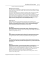
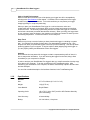
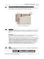
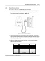
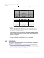
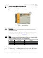
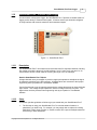
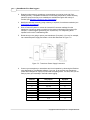
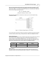
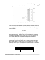
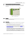
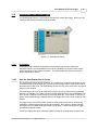
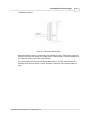
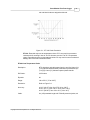
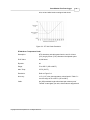
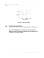
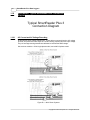
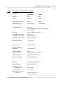
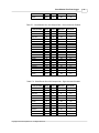
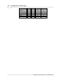
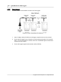
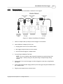
45
SmartReader Plus Data Loggers
other (positive) wire to the "+" terminal. The following table lists the ANSI color code for
the thermocouple wires:
Thermocouple Type
Positive (+) Wire
Negative (-) Wire
J
White
Red
K
Yellow
Red
T
Blue
Red
S
Black
Red
E
Violet
Red
Figure 5-2: SmartReader Plus 5 Thermocouple Connection
2.
Connect the logger to your computer and run TrendReader. Select the equation number
for each active thermocouple channel (refer to the Specifications section).
3.
Check that you have the thermocouple's polarity correct by warming its tip. You will see
the Realtime temperature increase if the wires are connected correctly. If the
temperature decreases, reverse the connections.
NOTE: The inputs are not isolated from each other (they use the same common
"-" terminal internally). This means that the thermocouple tips cannot be touching
each other. If they are touching or are fastened to a conducting surface like a
metal frame, some looping can occur and the readings may fluctuate. They must
be insulated or prevented from making contact with each other electrically. Do
not use grounded thermocouples.
Copyright © 2010 ACR Systems Inc. All Rights Reserved.