1
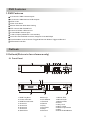
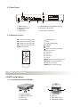
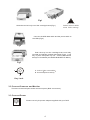
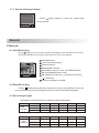
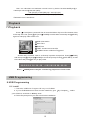
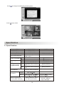
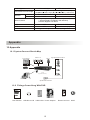
4 Channel Digital Video Recorder
User Manual
MODEL Q4DVR4RCM
4 Channel Digital Video Recorder
Protect Your Investments.
www.Q-See.com
All
cameras and accessories are compatible with Q4DVR4RCM
Directory
1.DVR Features-------------------------------------------------------------------------------------------------------------2
2.Outlook---------------------------------------------------------------------------------------------------------------------2
2.1 Front Panel-------------------------------------------------------------------------------------------------------------2
2.2 Rear Panel--------------------------------------------------------------------------------------------------------------3
2.3 Remote Control--------------------------------------------------------------------------------------------------------3
3.DVR Installation-----------------------------------------------------------------------------------------------------------3
3.1 Install Removable HDD Box-----------------------------------------------------------------------------------------3
3.2 Connect Cameras and Monitor-------------------------------------------------------------------------------------4
3.3 Connect Power---------------------------------------------------------------------------------------------------------4
4.DVR System Boot---------------------------------------------------------------------------------------------------------5
4.1 Detecting Installed Hard Disk---------------------------------------------------------------------------------------5
4.2 Recovering Lost Data------------------------------------------------------------------------------------------------5
4.3 Restore Recording Process-----------------------------------------------------------------------------------------5
4.4 Main Screen------------------------------------------------------------------------------------------------------------5
5.DVR Setup-----------------------------------------------------------------------------------------------------------------6
5.1 Main Menu-------------------------------------------------------------------------------------------------------------6
5.2 Camera Select--------------------------------------------------------------------------------------------------------6
5.3 Record Select---------------------------------------------------------------------------------------------------------6
5.4 Record Mode----------------------------------------------------------------------------------------------------------6
5.5 Record Frame Rate---------------------------------------------------------------------------------------------------7
5.6 Record Video Quality--------------------------------------------------------------------------------------------------7
5.7 Record Schedule------------------------------------------------------------------------------------------------------7
5.8.Sub Menu-Auto Record-----------------------------------------------------------------------------------------------7
5.9.Sub Menu-Password Setup------------------------------------------------------------------------------------------7
5.10 Sub Menu-Password Change--------------------------------------------------------------------------------------7
5.11 Sub Menu-Picture setup--------------------------------------------------------------------------------------------8
5.12 Sub Menu-Time Setup-----------------------------------------------------------------------------------------------8
5.13 Sub Menu-PTZ Setup------------------------------------------------------------------------------------------------8
5.14 Hard Disk Setup------------------------------------------------------------------------------------------------------9
5.15 Alarm Setup-----------------------------------------------------------------------------------------------------------9
5.16 NTSC/PAL Output Select-----------------------------------------------------------------------------------------10
5.17 Restore to Factory Default----------------------------------------------------------------------------------------11
6.Record---------------------------------------------------------------------------------------------------------------------11
6.1 Start Recording-------------------------------------------------------------------------------------------------------11
6.2 Stop Recording-------------------------------------------------------------------------------------------------------11
6.3 Recording Length----------------------------------------------------------------------------------------------------11
7.Playback-----------------------------------------------------------------------------------------------------------------12
8.USB Programming-----------------------------------------------------------------------------------------------------12
8.1 Install------------------------------------------------------------------------------------------------------------------12
8.2 Program Interface----------------------------------------------------------------------------------------------------13
9.Specification------------------------------------------------------------------------------------------------------------14
10. Appendix------------------------------------------------------------------------ -------------------------- --------------15
10.1 System Connect Sketch Map --------------------------------------------------------- ------------------ ----------15
10.2 Fittings Come Along With DVR------------------------------------------------------- ----------------- -----------15
Q-SEE Product Warranty---------------------------------------------------- ---------------------------------- ---------16
1
DVR Features
1.DVR Features
4 Channels - BNC Camera Inputs
2 Channels - BNC Monitor/VCR Outputs
NTSC / PAL
Video Loss Alarm
Motion Detection With Area Setting
PTZ Control With RS485 Port.
Connect PC With USB 2.0 Port
4 Sets NO/NC Sensor Input
1 Alarm Output (2A 28VDC / 2A 125 VAC)
One ATA-100 Hard Disk Interface, Support Over 200G Byte
Time Schedule record / Sensor Triggered Record / Motion Triggered Record
IR Remote Controller
Outlook
2.Outlook(Picture is for reference only)
2.1 Front Panel
UP
PWR
CH1
CH3
CH2
QUAD
CH4
HDD
MENU
ESC
PAUSE
REW
PLAY
STOP
FWD
PTZ
SEL
EDIT
REC
DUWN
UP
PWR
CH1
CH2
CH3
CH4
QUAD
HDD
MENU
ESC
REW
PAUSE
PLAY
FWD
STOP
PTZ
SEL
EDIT
REC
DUWN
1.HDD Tray Door
2.Power Indicator
3.HDD Run Indicator
4.Channel 1
5.Channel 2
6.Channel 3
7.Channel 4
8.Quad View
9.Move up
10.IR Window
11.Rewind
12.Pause
13.Play
14.Forward
15.Stop
16.Record
2
17.Menu /Exit
18.Move Down
19.Select /Edit
20.Vent
21.Key Lock
22.Door Latch
23.HDD Tray Handle
24.Key
25.PTZ Enable Button
2.2 Rear Panel
POWER
CAUTION
RISK OF ELECTRIC SHOCK
DO NOT OPEN
CH1
CH3
CH2
CH4
1
3
4
CAUTION: TO REDUCE THE RISK OF ELECTRICAL SHOCK.
DO NOT OPEN COVERS. NO USER SERVICEABLE
PARTS INSIDE. REFER SERVICING TO QUALIFIED
SERVICE PERSONNEL..........................................
WARING: TO PREVENT FIRE OR SHOCK HAZARD. DONOT
EXPOSE UNITS NOT SPECIFICALLY DESIGNED
FOR OUTDOOR USE TO RAIN OR MOISTURE.....
VIDEO INPUT
VIDEO OUTPUT
DC 12V
RS485
1.
2.
3.
4.
2
Video Output
DC Power Switch
USB Port
Video Input
SENSOR
ALARM
5. RS485/Sensor Input/Alarm Output
6. DC Power Input Jack
7. Case Ground Terminal
2.3 Remote Control
<<: Reverse Play
> : Play
>>: Fast Forward Play
: Record
|| : Pause
CH1: Select or enlarge CH1
CH2: Select or enlarge CH2
CH3: Select or enlarge CH3
CH4: Select or enlarge CH4
QUAD: Quad View
CH1
CH2
CH3
: Stop recording or playing
PTZ: PTZ control
Z-: Zoom out
F+: focus+
Z+: Zoom in
F-: focusMENU: Enter or exit setup menu
SEL/EDIT: Change selection
UP: Move up prompt
DOWN: Move down prompt
CH4
QUAD
Z-
F+
Z+
F-
PTZ
MENU
UP
SEL/EDIT
DOWN
DVR
DVR Installation
3.DVR Installation................................................................
3.1 Install Removable HDD Box
1.
2.
3.
4.
5. Tray handle
6. Air Vent
7. HDD data cable
8. HDD power cable
Power Indicator
HDD Run Indicator
Key Lock
PVC Frame
3
Fig1
Slide the carrier body out of the cartridge frame (Fig1)
CAUTION ........
DON'T take out HDD
when DVR running!
Connect the HDD data cable and the power cable to
the HDD (Fig2)
Fig2
Push the tray into the cartridge frame until fully
inserted and handle pushed downward (Fig3). Lock
tray in place and power up unit. A New HDD should
always be formatted (see HARD DISK SETUP Menu).
Fig3
A
A: Locked Non-removable
B: Unlocked(Removeable)
B
Key Lock
3.2 Connect Cameras and Monitor
There are 4 camera inputs and 2 monitor outputs ( BNC connectors).
3.3 Connect Power
Please use only the power adapter supplied with your DVR.
4
DVR System Boot
4.DVR System Boot
4.1 Detecting Installed Hard Disk
After connecting the power, system will boot-up and
detect installed hard disk. On Monitor it will show Master
and Slave hard-disk information.Please make reference to
hard disk manual to configure hard disk sequence. (Master
or Slave).......................................................................
Checking
HDD
MASTER ExcelStor.Technolo
SLAVE NONE
Monitor
Digital video Recoder Monitor
UP
DATA+
POWRE
MENU
Dual
PAL NTSC
4
DOWN
DATA
4.2 Recovering Lost Data
Power interruption can cause data to be lost. System will
ask: Recover HDD , Please press [
SEL/EDIT] to
proceed if HDD contains video you wish to save. Press
[
MENU](NO) for faster reboot without saving video. ........
HDD: RECOVER HDD?
04811-10735
(SELECT)YES (MENU)NO
Monitor
Digital video Recoder Monitor
UP
DATA+
POWRE
MENU
4
Dual
PAL NTSC
DOWN
DATA
4.3 Restore Recording Process
POWER ERROR DETECTED
RESTORE HARD DISK
OK
When power-error happen during recording process,
system will automatically restore recording process after
power Re-connected..........................................................
RESTORE RECORD
MODE
OK
Monitor
Digital video Recoder Monitor
UP
DATA+
POWRE
MENU
Dual
PAL NTSC
4
DOWN
DATA
4.4 Main Screen
Monitor
Digital video Recoder Monitor
UP
DATA+
POWRE
Firstly, The DVR to start for system working.DVR will be
sense of four cameras are shown on the monitor................
Upper left: ratio of hard disk space used......................
Middle: channel name(CH1
CH4). .............................
Bottom right: date andtime show on there.DVR is waiting
for key function,press[
MENU] into DVR setup process.
MENU
4
Dual
PAL NTSC
DOWN
DATA
5
DVR Setup
5.DVR Setup
5.1 Main Menu
Press[
MENU] to enter MAIN MENU, use [ UP] and
[
DOWN] to select item, press [
SEL/EDIT] to modify
setting and [
MENU] to confirm and exit......................
Monitor
Digital video Recoder Monitor
UP
DATA+
POWRE
MENU
Dual
PAL NTSC
4
DOWN
DATA
Menu Directory
Camera Select
Record Select
Record Mode
Record Frame Rate
Auto Recode
Video Quality
Main Menu
Password Setup
Record Schedule
Password Change
Sub Menu
Picture Setup
Hard Disk Setup
Time Setup
PTZ Setup
Alarm Setup
Restore Factory Default
5.2 Camera Select
8%
OFF
OFF
1
3
2
4
OFF
OFF
2008/08/08 08:08:08
Monitor
Digital video Recoder Monitor
UP
DATA+
MENU
4
POWRE
Your DVR can display 4 cameras on one screen (Quad
Mode). You can configure which camera(s) to display.......
Press [
SEL/EDIT] to change the setting or press
[
CH1] [
CH2] [
CH3] [
CH4] to set each
channel separately. If a channel is not used, the system
will display OFF on the monitor for that channel...........
Dual
PAL NTSC
DOWN
DATA
5.3 Record Select
Configure which channel is allowed to record.
5.4 Record Mode
Each Mode
Compress and record each channel video separately, therefore, user
can enlarge single channel video to full screen display. For example,
user can turn off record function of CH~1 and CH~2 and then system
only record CH3 and CH4 video. .......................................................
Press[
CH1], [
CH2], [
CH3], [
CH4] to switch channel to
display when playback recorded video. ..............................................
Only in this mode, when system is in watching mode or recording mode,
press [
QUAD] button over 3 seconds to make each channel video
enlarge to full screen and then display in quad mode in sequence again
6
and again, DVR will not change its state until user press any key..........
Quad Mode
Compress and record all 4 channel video into one file, therefore user
can not enlarge single channel to full screen. User can't use the each
mode record in this mode. Record frame rate will affect the movement of
object in recorded video. More frames means more smooth movement
and cost more hard disk space. System default value is 25 fps, that
means system will record 25 frame per second. User can set frame rate
as 25
8
6
4
3
2
1 frames per second. ................................
AUDIO RECORD (in SUB MEMU) is ON, User can set frame rate as 25
If
6
12
12
8
4 frame s per second. (Please refer to 5.8 AUDIO RECORD .) .............................
5.5 Record Frame Rate
Record frame rate will affect the movement of object in recorded video.More frames
means more smooth movement and cost more hard disk space. System default value is
25 fps, that means system will record 25 frame per second. User can set frame rate as
25
12
If
8
8
6
4
3
1 frames per second. ...........................................................
2
AUDIO RECORD
6
(in SUB MEMU) is ON , User can set frame rate as 25
4 frames per second. (Please refer to
5.8 AUDIO RECORD
12
.) .......................
5.6 Record Video Quality
There are three different video quality settings: High
Normal and Low. The higher
the video quality is set, the more space is consumed on the hard disk.
Record frame rate, record quality, and hard disk size affects the total record time of
all DVR systems.
5.7 Record Schedule
User can setup video record method by time,sensor Triggered and Motion Triggered.
RECORD SCHEDULE
+TTTTTTTATATTTTAATTTTTTTT+
0
3
6
9
12 15 18 21 24
PRESS(UP.DOWN). THEN(SELECT)
PRESS(MENU) TO EXIT
Monitor
Digital video Recoder Monitor
UP
DATA+
MENU
4
Dual
PAL NTSC
DOWN
DATA
POWRE
No Record..........................................................
T Continue, (System Default). ...................................
A Sensor Triggered or Motion Triggered. ....................
Cooperate with many kinds of external sensor equipment
like PIR, Gas sensor. DVR will not record video until external
sensor was triggered and output signal to notify DVR during
this specified period of time. ................................................
Button function:..................................................................
[
UP] [
DOWN]:move the prompt.............................
5.8 Sub Menu-Auto Record
When you choose ON DVR will be active to record automatically if DVR has not
been operated in five minutes.
When you choose OFF DVR will not record until you press [ RECORD] button.
5.9 Sub Menu-Password Setup
When password set is ON , Stop recording or enter menu will need Password, If
password set is OFF , All password will be cancelled.
5.10 Sub Menu-Password Change
System default password: Press six times of [
7
CH1] button
All keys can be used as password key except [
MENU]
key, which is used for confirming and exit.........................
Monitor
Digital video Recoder Monitor
UP
DATA+
POWRE
MENU
4
Dual
PAL NTSC
DOWN
DATA
5.11 Sub Menu-Picture Setup
HUE
SATURATION
> SATURATION
CONTRAST
BRIGHTNESS
60
80
50
> SATURATION
CONTRAST
BRIGHTNESS
60
80
50
> SATURATION
CONTRAST
BRIGHTNESS
60
80
50
> SATURATION
CONTRAST
BRIGHTNESS
60
80
50
CONTRAST
UP
DATA+
0-99
0-99
Button function:
[
POWRE
MENU
4
0-99
BRIGHTNESS
Monitor
Digital video Recoder Monitor
: 0-99
UP][
DOWN]: move the prompt
Dual
PAL NTSC
DOWN
DATA
[
REW]: Increase Value
[
FWD]: Reduce Value
[CH1~CH4,QUAD]: Select Channel
[
MENU]: exit.
5.12 Sub Menu-Time Setup
TIME SETUP
>
Configure DVR system time. Press[
2008/08/08 08:08:08
PRESS(UP,DOWN). THEN(SELECT)
PRESS(MENU) TO EXIT
to move prompt and press [
[
UP] and [
DOWN]
SEL/EDIT] to modify. Press
MENU] to save and exit.............................................
Monitor
Digital video Recoder Monitor
UP
DATA+
POWRE
MENU
Dual
PAL NTSC
4
DOWN
DATA
5.13 Sub Menu-PTZ Setup
CHANNEL: Camera Number.
ADDRESS: Dome's address
PTZ SETUP
PROTOCOL
BAUPRATE
<
CHANNEL ADDRESS
1
2
3
4
1
2
3
4
PELCO-D
PELCO-D
PELCO-D
PELCO-D
(<.>) MOVE (<<.>>) AD JUST
2400
2400
2400
2400
PROTOCOL: Including
SAMSUNG
(MENU)EXIT
BO1
0-255
.
PELCO-D
PELCO-P
NEON
CTNCOM
,
Setting the protocol according to the dome's protocol.
Monitor
Digital video Recoder Monitor
UP
DATA+
MENU
4
Dual
PAL NTSC
DOWN
DATA
POWRE
BAUD RATE: Press [
value 1200 2400
4800
SEL/EDIT] button to select the
9600
19200 bps.
If you have a compatible speed dome camera attached to your DVR, press the
PTZ
UP
button and select the camera number that you wish to control. You can use
DOWN
RIGHT
and
LEFT
horizontal and vertical positioning. Press the
PLAY
buttons to control the speed dome's
REW
,
FWD
,
PAUSE
, and
buttons to control the speed dome s ZOOM and FOCUS functions.............
NOTE: Make sure all the lines are correctly connected to the speed dome, and
the proper protocol, baud rate, and address are set per its instructions..............
8
5.14Hard Disk Setup
OVERWRITE ENABLED: If you choose YES, recording
continues and overwrite previous recording when hard disk
drive space is full............................................................
If you choose NO, the recording session stops when all
hard disk drive is full for recording. ..................................
Monitor
Digital video Recoder Monitor
UP
DATA+
MASTER HDD SIZE: It shows the size of the primary
POWRE
MENU
Dual
PAL NTSC
4
DOWN
DATA
hard disk drive installed in the DVR. .................................
MASTER HDD USED: It shows the space used on the first hard disk drive for
recording and the percent Of the used hard disk. .......................................................
MASTER HDD FORMAT: If you format the hard drive, it will erase all the data
recorded on the first hard disk drive. .........................................................................
Notice: when you first use a HDD in the DVR, please use this function to format
the HDD. Otherwise the computer will not find the HDD when you connect the DVR
to the computer by using the USB cable. ................................................................
SLAVE HDD SIZE: It shows the space the secondary hard disk drive installed in the
DVR. .....................................................................................................................
SLAVE HDD USED: It shows the space used on the primary hard disk drive for
recording. .............................................................................................................
SLAVE HDD FORMAT: If you format the hard drive, it will erase all the data recorded
on the secondary hard disk drive..............................................................................
5.15 Alarm Setup
Alarm Record Duration: The number indicates how long
triggered recording lasts after the sensors are triggered or
the movements in front of the camera. ...............................
ALARM SETUP
ALARM RECORD DURATION
ALARM DURATION
BUZZER DURATION
10
OFF
OFF
Alarm Duration: It controls how long (in seconds) the
SENSOR SETUP
MOTION SETUP
alarm lasts after the system is triggered. ...........................
PRESS(UP,DOWN). THEN(SELECT)
PRESS(MENU) TO EXIT
Buzzer Duration: Buzzer time set (OFF
Monitor
Digital video Recoder Monitor
UP
DATA+
POWRE
MENU
4
20
25
05
10
15
30 seconds and CONT) , User can press
Dual
PAL NTSC
DOWN
DATA
[
SEL/EDIT ] to set the time .When Buzzer Time is OFF ,
All the buzzers will be shut off. When
CONT
Buzzers Time
is
,the buzzer will work continuously.....................
Sensor Setup:...........................................................
There are 3 different modes for sensor setting: NOT
INSTALLED, NORMAL-CLOSE and NORMAL-OPEN. ........
SENSOR SETUP
< CHANNEL-1
CHANNEL-2
CHANNEL-3
CHANNEL-4
NOT INSTALLED
NOT INSTALLED
NOT INSTALLED
NOT INSTALLED
It depends on what type of external sensor you use. If
TYPE: NORMAL-OPEN
TYPE: NORMAL-OPEN
TYPE: NORMAL-OPEN
TYPE: NORMAL-OPEN
sensor's output is NORMAL-OPEN then select NORMAL-
PRESS(UP,DOWN). THEN(SELECT)
PRESS(MENU) TO EXIT
OPEN mode in DVR........................................................
Monitor
Digital video Recoder Monitor
UP
DATA+
POWRE
MENU
4
If sensor triggered by an intruder then the cable line
Dual
PAL NTSC
DOWN
DATA
connects to DVR input terminal will notify system to start
recording. ......................................................................
There are four pairs of input terminal supported by DVR.
1
2
3
4
Push the UNLOCK BUTTON above the wire hole to insert
or pull out a wire.
RS485
SENSOR
ALARM
9
Installation example diagram:
POWER
CAUTION
RISK OF ELECTRIC SHOCK
DO NOT OPEN
CH1
CH3
CH2
CH4
1
2
3
4
CAUTION: TO REDUCE THE RISK OF ELECTRICAL SHOCK.
DO NOT OPEN COVERS. NO USER SERVICEABLE
PARTS INSIDE. REFER SERVICING TO QUALIFIED
SERVICE PERSONNEL..........................................
WARING: TO PREVENT FIRE OR SHOCK HAZARD. DONOT
EXPOSE UNITS NOT SPECIFICALLY DESIGNED
FOR OUTDOOR USE TO RAIN OR MOISTURE.....
VIDEO INPUT
VIDEO OUTPUT
DC 12V
RS485
SENSOR
ALARM
Alarm
PTZ Setup
1
2
3
4
Power
RS485
SENSOR
ALARM
Power
PIR Sensor
Connect PIR sensor NO/NC output to DVR input terminal.(Max. 5V DC)
Motion Setup: The first step, User need setup video
MOTION DETECTION SETUP
CHANNEL
CHANNEL
CHANNEL
CHANNEL
1
1
1
1
SENSITIVITY
SENSITIVITY
SENSITIVITY
SENSITIVITY
CHANNEL
CHANNEL
CHANNEL
CHANNEL
1
1
1
1
AREA
AREA
AREA
AREA
record method by Motion Triggered. Please make
4
4
4
4
Reference to 5.7. ...........................................................
SET
SET
SET
SET
CHANNEL 1- 4 SENSITIVITY: User can press
PRESS(UP,DOWN). THEN(SELECT)
PRESS(MENU) TO EXIT
[
Monitor
Digital video Recoder Monitor
UP
DATA+
SEL/EDIT] to adjust sensitivity grade of motion
POWRE
MENU
4
Dual
PAL NTSC
DOWN
DATA
detection. .......................................................................
High(1----------9,OFF) Low, When it's off, the channel
can not be triggered by movement...................................
CHANNEL 1- 4 AREA SET: Press[
SEL/EDIT] to enter area setting state, the picture
of selected channel is divided into 144(12
12) blocks, and then press[
UP] to move up, press [
CH1] to move
left, press [
CH2] to move right, press [
DOWN]to move
down, press[
SEL/EDIT] to set the block is active or not. When the block is transparent,
it's active to record; when the block is covered by shadow, It can not be recorded. ...........
5.16 NTSC/PAL Output Select
After completed the
MOTION SET
, User can exit MENU, And press [
REC ] to
s ta r Mo tion Re cord.
Disconnect the power supply. Change jumper JS1 to select NTSC or PAL video
output format according to the silkscreen on the circuit board.....................................
NTSC/PAL Select
10
5.17 Restore Factory Default
Press [
ALL SETTING DATA IS INITIAL IZED
EDIT] Button to make the system load
factory default.
Monitor
Digital video Recoder Monitor
UP
DATA+
POWRE
MENU
Dual
PAL NTSC
4
DOWN
DATA
Record
6.Record
6.1 Start Recording
Press [ REW] to start recording. System will display some information on Screen.
Only EACH MODE can enlarge single channel to full screen display
Hard Disk Used
R
Recording Symbol
Channel Names
Mode(QUAD or EACH)
Status(REC, Play, FF1, FF2, FF3, REW, PAUSE)
A
HD Info.([M] Master disk in use)
Monitor
Digital video Recoder Monitor
UP
DATA+
POWRE
Schedule ((T) Continuous
MENU
4
Dual
PAL NTSC
DOWN
DATA
(A) Sensor or Motion
( ) No Record
The time and date of the DVR
6.2 Stop Recording
Press[
STOP] and system may prompt you to input your password. Only your
correct password can stop recording process (if you have this feature enabled)...........
6.3 Recording Length
Estimated record time based on 120G Byte HDD (Quad Mode)
Quality
Frame Rate
30
5
7
1
HIGH
20K / frame
58
117
251
1748
NORMAL
15K / frame
78
155
333
2330
LOW
12K / frame
97
194
416
2913
Format
Quality
Frame Rate
30
5
7
1
PAL
(HOURS)
HIGH
20K / frame
70
291
1748
NORMAL
15K / frame
93
194
388
2330
LOW
12K / frame
117
243
485
2913
Format
NTSC
(HOURS)
11
146
User can calculate and estimate record hours by below formula120G Byte @ 7
frames per second @ Normal quality
120 (G byte) x 1024 (M byte) x 1024 (K byte)
15 (Kbyte/frame) x 7 (frame/sec) x 60 (sec) x 60 (min)
Estimate hours is 332 Hours
Playback
7.Playback ................................................................
Press [
PLAY] then system will list all recorded video clip from HD. Newest video
will at top of the list, press [
UP] and [
DOWN] to select start time and press[
PLAY]
again to start play video to the end..............................................................................
HDD Information
Start Time
End Time
TIME: Continuous record file
Monitor
Digital video Recoder Monitor
UP
DATA+
POWRE
MENU
4
ALARM: Sensor or Motion Triggered
Dual
PAL NTSC
DOWN
DATA
<
Another way to search video is to directly input the time period. Press[
FWD]
and then press[ UP] and[
DOWN] to move the prompt. Press[
SEL/EDIT] to edit
time value and press[ PLAY] to play video..............................................................
0 8 /0 8 / 0 8 0 8 : 08 : 0 8
Note: [
-- 0 8 / 0 8 / 0 8 08 : 0 8 : 08
PAUSE] button may be used during playback to freeze video.
USB Programming
8.USB Programming
8.1 Install
1. Place the USB Driver Program CD into your CD ROM.
2. If your CD ROM does not auto-run the install CD, go to
your CD drive, and click on Setup.exe
My Computer , select
. ................................................................
3.Follow the prompts on your PC to finish the installation......................................
12
8.2 Program Interface
To run the program( Double click
icon on your desktop)...............................
System will detect the HDD automatically when you connect the USB cable to your
PC. .......................................................................................................................
Note: If the HDD is not detected, please perform
the followings steps:(1) Close the USB program
window, and remove the USB cable, (2) Press
[
PLAY] twice to enter the DVR into the Playback
mode,(3)Connect the USB cable to PC again.
Please allow up to 30 seconds for the DVR to
show video on your PC.........................................
Button functions
19 20 2122
1
2
3
4
5
6
7
8
9
10 11 12 13 14 15 16 17
1 Save Frame
2 Save Video Clip
3 Config
4 Event List
5 Channel 2
6 Channel 1
7 Quad Mode
8 Channel 3
9 Channel 4
10 Fast Reverse
11 Back one frame
Press
18
12
13
14
15
16
17
18
19
20
21
22
to open the event video list.
Save Frame
Save Video Clip
Config
Event List
13
Reverse play
Pause
Play
Forward one frame
Fast forward
Scroll Bar
Version of the program
Play DVR video file
Play PC video file
Minimize viewer
Close viewer
Press
Press
to configue the DVR play/record system.
to play video .
Specification
9. Specification
ITEM
Video Format
Operation System
Camera Input Channel
DESCRIPTION
NTSC / PAL
STAND ALONE
4 channel Composite BNC
2 channel Composite BNC
USB 2.0 Port
NTSC
120 frames
Display Frame Rate
PAL
100 frames
Max 30 fps (Quad)
NTSC
Recording Frame
Rate
Max 25 fps (Quad)
PAL
NOTE
STAND-ALONE
Video Output Channel
Each Channel =
Recording Frame
Rate(Each Mode)
NTSC 30 Number of Source(frames)
Each Channel =
PAL 25 Number of Source(frames)
Max. 25 frames
(Each Channel)
Continuous, Schedule, Motion
Triggered , Sensor Triggered
Record Modes
Display
Resolution
4 30 frames
4 25 frames
Quad Mode
Quad Mode
Max. 30 frames
(Each Channel)
NTSC:720 480
PAL:720 576
NTSC:320 112, 640 224
Record PAL:320 136, 640 272
Video Compression
Format (Each Channel)
Modified Motion-JPEG
(12-20K bytes/frame)
14
Quad:640 224 (total)
Each:640 224
Low :12K Byte
Normal :15K Byte
High : 20K Byte
Over 200G Byte
HDD Support
Estimated Record Length
Method
Search
Full Screen
ATA -100 Interface
120G Hard disk @ 7 fames per second @ Normal Quality
(120 1024 1024 K byte) ( 7 15 60 60 ) = 332 Hours
Time, Date, Event
YES
4 Inputs (Normally Open / Normally Closed)
1 Output (Relay 2A 28VDC / 2A 125VAC)
Camera Signal Loss Alarm
Sensor, Alarm
YES
YES
Length 15.7 in
PTZ
USB
Dimensions
PELCO-D PELCO-P
USB2.0 Port for playback
Width 10.8 in
Height 2.7 in
Appendix
10.Appendix
10.1 System Connect Sketch Map
Sensor 1~4
TV or Monitor
Alarm
High Speed Dome Camra
Monitor
Digital video Recoder Monitor
UP
DATA+
POWRE
MENU
4
Dual
PAL NTSC
DOWN
DATA
VCR
4 Channel Digital Video
Recorder
DVR
(Digital Video Recorder)
Camera 1~4
PC
Speed Dome Controller
10.2 Fittings Come Along With DVR
CH1
CH2
CH3
CH4
QUAD
4 Channel Digital Video Recorder
Z-
F+
User Manual
Z+
F-
MODEL Q4DVR4RCM
PTZ
MENU
UP
4 Channel Digital Video Recorder
SEL/EDIT
CMPACT
DOWN
DVR
23min 215MB
Protect Your Investments.
www.Q-See.com
All
cameras and accessories are compatible with Q4DVR4RCM
User Manual
USB Driver CD USB Cable Power Adapter
15
Remote Control
GNG
Affix Proper
Postage Here
Q-See Product Line
By
Digital Peripheral Solutions, Inc.
8015 E. Crystal Drive
Anaheim, CA 92807
Q-SEE PRODUCT LINE WARRANTY
PURCHASER'S SALE REMEDY UNDER
THE ABOVE WARRANTIES SHALL BE
REPAIR OR REPLACEMENT AS STATED
ABOVE. DPS INC'S SALE AND
EXCLUSIVE LIABILITY FOR ANY AND
ALL LOSSES AND DAMAGES ARISING
OUT OF ANY CAUSE WHATSOEVER
SHALL IN NO EVENT EXCEED THE
A C T U A L P R I C E P AI D F O R T H E
PRODUCT.
IN NO EVENT SHALL DPS INC. BE
LIABLE FOR ANY DAMAGES, WHETHER
S P E C I A L , I N C I D E N T AL , I N D I R E C T ,
E X E M P L A R Y, C O L L AT E R A L O R
CONSEQUENTIAL, ARISING FROM
BREACH OF WARRANTY, BREACH OF
CONTRACT, NEGLIGENCE OR UNDER
ANY OTHER LEGAL THEORY ARISING
F R O M , T H E WA R R A N T Y H E R E I N
S TAT E D O F T H E P U R C H A S E O F
P R O D U C T, I N C L U D I N G W I T H O U T
LIMITATION.
16
EXCEPT AS EXPRESSLY PROVIDED
HEREIN, THERE ARE NO OTHER
WARRANTIES, WHETHER EXPRESSED,
STATUTORY, OR IMPLIED, INCLUDING
A L L I M P L I E D WA R R A N T I E S O F
MERCHANTABILITY AND FITNESS FOR
A PARTICULAR PURPOSE
SOME STATES AND COUNTRIES (SUCH
AS THE UNITED KINGDOM) DO NOT
ALLOW THE EXCLUSION OR
L I M I TAT I O N O F I N C I D E N TA L O R
CONSEQUENTIAL DAMAGES;
THEREFORE THE ABOVE EXCLUSION
OR LIMITATION MAY NOT APPLY TO
Y O U . T H I S WA R R A N T Y G I V E S Y O U
SPECIFIC LEGAL RIGHTS AND YOU
M AY A L S O H A VE O T H E R R I G H T S
WIHCH VARY STATE TO STATE AND
COUNTRY TO COUNTRY.
Register Your Q-SEE Product Online Now
YOU MUST REGISTER YOUR Q-SEE PRODUCT TO RECEIVE TECHNICAL SUPPORT!
Just fill out this card and fax to 714-998-3509, mail to us or register online at www.q-see.com.
Mr.
Ms. Name:
Title:
Street Address:
City:
)
Phone: (
Product Model:
Serial Number:
Purchased From:
Name:
Company:
State/Province:
Email:
Suite or Apt. #:
Zip/Postal Code:
Why did you buy your Q-SEE Product
(check no more than 3)
Price
Capacity
Compatibility
Reputation
Performance Quality/Reliability
Where will you be using this Q-SEE Product?
Home
Corporate Office
Professional Office
On the Road
State/Local Government
Studio
College/University
High School
Federal Government
Other
Elementary Middle School
Where did you find out about this product?
Search Engine
Store
Other
Costco
Friend/Relative
Would you like to receive information about
new Q-SEE Products and promotions via email?
No
Yes
Q-SEE Product Warranty
insurance prepaid. Replaced Products and parts
shall become DPS INC. s property. If DPS INC.,
after examination and testing, determines that
the returned Product is not defective, DPS lNC.
shall so advise the purchaser and shall dispose of
such Products in accordance with the
purchaser s instructions, at the purchaser s cost.
In such case, Purchaser shall reimburse DPS
INC. at DPS INC. s then-current rates for
examination and testing.
Limited Warranty and Limitation of Liability.
DPS INC. warrants its products to be free from
defects in material and workmanship under
normal use and service unless otherwise stated
in the product-specific documentation received
with the product. The above warranty period
shall begin on the date DPS INC. ships the
product to Purchaser or, if the Purchaser is an
authorized reseller of such DPS INC. products,
from the date the reseller ships to its original
customer.
The warranties set forth above shall not apply to,
and DPS INC. shall not be responsible for any
failures or deficiencies caused by misuse,
excessive use, improper installation,
unauthorized repairs or modifications, willful
damage, neglect, alterations, accidents or any
external cause, including but not limited to
power failure, exposure to smoke, dust,
humidity, or excessive heat, or repair by a party
other than DPS INC. DPS, INC s resellers are
not authorized to change the terms of this
warranty.
If the original retail purchaser returns the
Product to DPS INC., together with the dated
and serialized proof of purchase, transportation
and insurance prepaid, within the warranty
period and if DPS INC. determines that the
Product is defective within the terms of this
warranty, then DPS INC. shall, at its cost and
option, either repair or replace the Product with
new or reconditioned Products and parts. DPS
INC. shall return the repaired or replaced
products to the purchaser, transportation and
17
Digital Peripheral Solutions Inc
8015 E Crystal Drive
Anaheim, CA 92807
877-998-3440
Q-SEE Tech Support
IN USA
MONITOR:9am-5pm PST
Email: [email protected]
Website: www.q-see.com