1
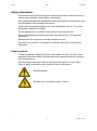
Content Imprint................................................................ Error! Bookmark not defined. Documentation Representative ....................... Error! Bookmark not defined. Content .......................................................................................................... 2 Preface ............................................................... Error! Bookmark not defined. Technical Support ........................................ Error! Bookmark not defined. Modifications to the Product ........................ Error! Bookmark not defined. Warranty ...................................................... Error! Bookmark not defined. Using the documentation ............................. Error! Bookmark not defined. Safety information ........................................................................................ 7 Hazard symbols ........................................................................................... 7 Signal words and their meaning in the safety information and instructions .................................................................................................. 8 Structure of the safety information and instructions ..................................... 8 Observe regulatory information ................................................................... 9 Proper/Designated Use ............................................................................... 9 Improper Use or Use Deviating from Intended Use ................................... 11 Qualifications of personnel / target group .................................................. 12 Storing the SMU .......................................................................................... 13 Storage conditions ..................................................................................... 13 Transporting the SMU ................................................................................ 14 Decoding the type label .................................... Error! Bookmark not defined. Checking the scope of delivery ................................................................. 15 SMU Features .............................................................................................. 16 Dimensions ................................................................................................. 17 Fastening / Mounting the SMU................................................................... 18 Fastening the SMU temporarily to magnetizable surfaces......................... 19 Permanent fastening of the SMU on the top hat rail .................................. 20 Connecting the SMU ................................................................................... 21 SMU interface overview ............................................................................. 21 Sensor interface A - TCM IN / TMS IN ...................................................... 23 Sensor Interface B - TWS-C IN ................................................................. 23 Interface C - TCM OUT / TMS OUT........................................................... 23 8-pin connection cable, open cable end: ................................................ 24 Interface D - TWS-C OUT.......................................................................... 25 5-pin connection cable, open cable end: ................................................ 25 Interface E - voltage supply ....................................................................... 26 Interface F - USB ....................................................................................... 26 Interface G ................................................................................................. 27 HSI (Schroeder Industries Sensor Interface) – SMU 126x … ................ 27 ETH (Ethernet) – SMU 127x … .............................................................. 27 Connecting the sensors ............................................................................. 28 Examples of connection ............................................................................. 30 SMU126x <-> TCM / TWS-C ..................................................................... 30 SMU12x1 <-> Bluetooth ............................................................................ 31 SMU127x <-> TCM / TWS-C -> LAN ......................................................... 32 Operating the SMU...................................................................................... 33 Display (TCM and TWS-C) ........................................................................ 33 Display (TMS and TWS-C) ........................................................................ 34 Internal measurement data memory .......................................................... 35 Keyboard elements .................................................................................... 36 Activating/deactivating key lock ................................................................. 36 Switching the display on and off ................................................................ 37 Scrolling through the displays .................................................................. 38 TCM displays ............................................................................................. 38 Display ISO.SAE .................................................................................... 38 Display ISO.NAS .................................................................................... 39 Measured variables TCM........................................................................... 40 Measured variable "ISO" ........................................................................ 40 Measured variable "SAE" ....................................................................... 40 Measured variable "NAS" ....................................................................... 40 Service variables (only for TCM) ............................................................... 41 Service variable "Flow" ........................................................................... 41 Service category "Out" ........................................................................... 41 Service variable "Drive" .......................................................................... 41 Service category "Temp" ........................................................................ 41 TMS displays ............................................................................................. 42 Measured variables TMS ........................................................................... 43 Measured variable "SUM" ...................................................................... 43 Measured variable "CYCLE" .................................................................. 43 Representation of numbers over 9999 ................................................... 43 Service variables (only for TMS)................................................................ 44 Service variable "Status" ........................................................................ 44 Service variable "Fi" ............................................................................... 44 Service category "Temp" ........................................................................ 44 AquaSensor TWS-C measured variables ............................................... 45 Measured variable "Water saturation" .................................................... 45 Measured variable "Temperature" .......................................................... 45 Configuring the SMU .................................................................................. 46 PowerUp Menu .......................................................................................... 47 DAT.TIM – date / time ............................................................................ 48 ADRESS – Setting HSI bus address / TCP/IP address .......................... 49 REC.MOD – Set data recording ............................................................. 51 DEL.MEM – Delete Memory ................................................................... 52 SENS A – Sensor A PowerUp menu ...................................................... 53 SENS B – Sensor B PowerUp menu ...................................................... 55 SEN.ADR – Set sensor address............................................................. 56 DFAULT – reset to factory settings ........................................................ 57 CANCEL ................................................................................................. 58 SAVE – store data .................................................................................. 58 Measuring Menu ........................................................................................ 59 RECORD – Record measurements........................................................ 60 MEMORY – show free memory space ................................................... 61 REC.TIM – Set recording interval ........................................................... 62 ED.MPNT – Change the name of measurement points ......................... 63 Setting OIL.CON – display screen for OilCondition sensors .................. 64 TP.UNIT – change the temperature units °C / °F ................................... 64 SENS A – Sensor A Measuring Menu .................................................... 65 SENS B – Sensor B Measuring Menu .................................................... 66 CANCEL ................................................................................................. 66 SAVE – save data .................................................................................. 67 USB interface .............................................................................................. 68 Copying measurements onto a USB data stick ......................................... 68 Data transmission failed - "ERROR COPY"............................................... 71 Bluetooth interface ..................................................................................... 72 Installing the Bluetooth USB adaptor ......................................................... 73 Guarantee and liability for the USB adapter ........................................... 73 Connecting the SMU via Bluetooth ............................................................ 73 Evaluating stored records .......................................................................... 74 Directories to store the records .................................................................. 74 Record file names ...................................................................................... 76 Evaluating the file containing the measurements ...................................... 77 The measurements are shown as dates ................................................ 79 Measurement value readouts with FluMoS .............................................. 80 Status messages / error messages ........................................................... 81 Disposing of the SMU ................................................................................. 85 Customer service .............................................. Error! Bookmark not defined. Model Code ....................................................... Error! Bookmark not defined. Measurement sensors combination ............. Error! Bookmark not defined. Factory default settings ............................................................................. 86 Accessories ................................................................................................. 87 Technical data ............................................................................................. 89 Overview - Compatible USB sticks............................................................ 90 EC declaration of conformity ........................... Error! Bookmark not defined. Index .................................................................. Error! Bookmark not defined. L-4335 SMU User Manual Safety information The device was built according to the statutory provisions valid at the time of delivery and satisfies current safety requirements. Any residual hazards are indicated by safety information and instructions and are described in the operating instructions. Observe all safety and warning instructions attached to the unit. They must always be complete and legible. Do not operate the unit unless all the safety devices are present. Secure the hazardous areas which may arise between the unit and other equipment. Maintain the unit inspection intervals prescribed by law. Document the results in an inspection certificate and keep it until the next inspection. Hazard symbols These symbols are listed for all safety information and instructions in these operating instructions which indicate particular hazards to persons, property or the environment. Observe these instructions and act with particular caution in such cases. Pass all safety information and instructions on to other users. General hazard Danger due to electrical voltage / current 7 EN Schroeder Industries L-4335 SMU User Manual Signal words and their meaning in the safety information and instructions DANGER DANGER indicates a hazard with a high risk and which will lead to death or serious injury if not avoided. WARNING WARNING indicates a hazard with a medium risk and which can lead to death or serious injury if not avoided. CAUTION CAUTION indicates a danger with a low risk and which can lead to minor injury if not avoided. NOTICE NOTICE indicates a danger which will lead to damage to property if not avoided. Structure of the safety information and instructions All warning instructions in this manual are highlighted with pictograms and signal words. The pictogram and the signal word indicate the severity of the danger. Warning instructions listed before an activity are laid out as follows: SIGNAL WORD HAZARD SYMBOL Type and source of danger Consequence of the danger ► Measures to avert danger 8 EN Schroeder Industries L-4335 SMU User Manual Observe regulatory information Also observe the following regulatory information and guidelines: Legal and local regulations for accident prevention Legal and local regulations for environmental protection Country-specific regulations, organization-specific regulations Proper/Designated Use WARNING Strong magnets on the SMU Life-threatening danger for persons with cardiac pacemakers ► Maintain sufficient clearance between yourself and the magnets NOTICE Connection of the SMU to board networks The SMU1200 will be destroyed ► Use the SMU only on board networks which have a central "Load Dump" fuse. The Load Dump with a maximum of 30 V DC must be installed and effective. NOTICE Exceeding the maximum permissible line length Erroneous or no communication ► Observe the maximum permissible line lengths 9 EN Schroeder Industries L-4335 SMU User Manual Only use the sensor for the application described in the following. The SensorMonitoring Unit is for connecting two sensors for the continuous monitoring of fluids in hydraulic and lubrication systems. By displaying, storing and forwarding measurement data for particle contamination in the ultra-fine or coarse particle range and for relative saturation of the fluid with water, it is possible to perform condition-based service and maintenance procedures. Any other use shall be deemed to be improper and not in keeping with the product's designated use. SCHROEDER INDUSTRIES accepts no liability for any damage resulting from such use. Proper or designated use of the product extends to the following: 10 Connection with the suitable sensors provided Observing all the notes contained in these operating instructions EN Schroeder Industries L-4335 SMU User Manual Improper Use or Use Deviating from Intended Use DANGER Hazard due to use of the unit other than that intended Bodily injury and damage to property will result when operated improperly. ► Never operate the sensor in potentially explosive atmospheres. ► The sensor is only to be used with the permitted media. Any use extending beyond or deviating therefrom shall not be considered intended use. Schroedr Industries llc will assume no liability for any damage resulting from such use. The user alone, shall assume any and all associated risk Improper use may result in hazards and/or will damage the sensor. Examples of improper use: 11 Operation in potentially explosive atmospheres. Operation with a non-approved sensor. Operation under non-approved operational conditions. Modifications to the sensor made by the user or purchaser. Improper connection of the voltage and sensor cables. Operation on board networks without central "Load Dump" fuse. EN Schroeder Industries L-4335 SMU User Manual Qualifications of personnel / target group Persons who work on the sensor must be aware of the associated hazards when using it. Auxiliary and specialist personnel must have read and understood the operating instructions, in particular the safety information and instructions, and applicable regulations before beginning work. The operating instructions and applicable regulations are to kept so they are accessible for operating and specialist personnel. These operating instructions are intended for: Auxiliary personnel: such persons have been instructed about the sensor and are aware of potential hazards due to improper use. Specialist personnel: such persons with corresponding specialist training and several years work experience. They are able to assess and perform the work assigned to them, they are also able to recognize potential hazards. Activity Person Knowledge Transport / storage Auxiliary personnel No specialist knowledge required Electric installation, Specialist personnel Safe handling/use of tools first commissioning, troubleshooting, Fitting and connection of electrical lines Knowledge of network communication Shutdown Knowledge of using Windows PCs and of program installation Product-specific knowledge Operation, operations control Specialist personnel Knowledge of using Windows PCs Product-specific knowledge Dismantling, disposal Specialist personnel Proper and environmentallyfriendly disposal of materials and substances Knowledge about reuse 12 EN Schroeder Industries L-4335 SMU User Manual Storing the SMU Make sure to store the SMU in a clean, dry place, in the original packing, if possible. Do not remove the packing until you are ready to install the unit. Storage conditions 13 Storage temperature: -40 °C … 80 °C / -40 °F … + 176 °F Relative humidity: maximum 95%, non-condensing EN Schroeder Industries L-4335 SMU User Manual Transporting the SMU WARNING Strong magnetic field around the magnets Life-threatening danger for persons with cardiac pacemakers ► Maintain sufficient clearance between yourself and the magnets NOTICE Strong magnetic field around the magnets Magnetic strips and magnetizable objects can be damaged. ► Maintain sufficient clearance from magnetic strips on credit cards, watches, jewelry, etc. Transport the SMU by hand. During transport, avoid any localized pressure points, especially on the displays. 14 EN Schroeder Industries L-4335 SMU User Manual Checking the scope of delivery The SMU comes packed and factory-assembled. Before commissioning the SMU, check the content of the package to make sure everything is present. The following items are supplied: Item Qty. Designation 1 1 SensorMonitoring Unit SMU 2 1 USB Memory stick 3 1 Connection cable, 5-pin with open cable end, L = 5 m 4 1 Connection cable, 5-pin, plug/socket, L = 5 m ZBE 30-05 5 1 Connection cable, 8-pin, plug/socket, L = 5 m ZBE 43-05 - 1 Top hat rail (35 mm), L= 200 mm - 1 Operating Instructions (this document) - 1 CD - FluMoS light ZBE 47S-05 1 15 3 2 EN ZBE 47S-05 4 ZBE 30-05 ZBE 43-05 5 Schroeder Industries L-4335 SMU User Manual SMU Features The SensorMonitoring Unit SMU is used for the presentation and memory storage of the measured values of Fluid Sensors. The following fluid sensors can be connected directly, depending on the SMU model: - ContaminationSensor TCM (sensor interface A) - Metal ContaminationSensor TMS (sensor interface A) - AquaSensor TWS-C (Sensor interface B) The measured values for the connected sensors are shown on the display. The values can be read off via USB memory stick for further processing and evaluation of data and thus simply transferred to Office applications, for example FluMoS or MS-Excel. Uses for the SMU include: - Presentation and memory storage of the measured values of Fluid Sensors - Parameterization of Fluid Sensors - Test installation for testing Fluid Sensors - Permanent installation of Fluid Sensors Advantages offered by the SMU unit: 16 - Cost-effective, easy-to-install solution - Simple processing and evaluation with FluMoS or MS Excel - USB interface for transferring data onto a USB memory stick - HSI interface for connecting HMG 3000 SERIES or CSI-F-10 or Ethernet interface for simple integration into an existing network via IP address - Bluetooth interface for data transfer and/or for visualization, e.g. on a smartphone / PC via FluMoS - Representation and/or parameterization of sensors without their own display (e.g. TWS-C) - Interface for routing the analog and/or switching outputs of connected Fluid Sensors EN Schroeder Industries L-4335 SMU User Manual Dimensions 224 124,5 61 52 35 70 140 Rear view: 17 EN Schroeder Industries L-4335 SMU User Manual Fastening / Mounting the SMU The SMU has the following two types of mounting as standard features WARNING Strong magnetic field around the magnets Life-threatening danger for persons with cardiac pacemakers ► Maintain sufficient clearance between yourself and the magnets CAUTION Strong magnets for fastening Danger of crushing ► Hold the SMU firmly on the edge for assembly. 18 EN Schroeder Industries L-4335 SMU User Manual Fastening the SMU temporarily to magnetizable surfaces The four high-performance magnets on the rear side provide fastening to metallic surfaces. Use the top hat rail mounting technique for permanent fastening, see page 20 The SMU can be readily released from the metallic surface by tilting. 19 EN Schroeder Industries L-4335 SMU User Manual Permanent fastening of the SMU on the top hat rail The SMU has a top hat rail receptacle on its rear side for the purpose of fastening it to 35 mm top hat rails in accordance with DIN EN 60715 TH35. To accomplish this, mount the top hat rail included in the scope of delivery to the desired position with 2 screws or use the top hat rail to be found in the control cabinet. Hang the SMU in the top hat rail with the top hat rail receptacle at the top. Pull the SMU slightly downward and to the rear until the lower guide of the top hat rail receptacle encloses the top hat rail. Now let go of the SMU. Make sure that the SMU is seated firmly on the top hat rail. Disassemble in reversed order of sequence. 20 EN Schroeder Industries L-4335 SMU User Manual Connecting the SMU Note the many different interfaces on the SMU before connecting. Described in detail in the following overview. SMU interface overview The SMU has sensor interfaces and interfaces as indicated below. G F A B C D E Connection Description A Sensor Interface A B Sensor Interface B C Interface, additional signals from sensor interface A D Interface, additional signals from sensor interface B E Supply voltage / HSI interface connection F USB interface G HSI interface for SMU 1260 ... Ethernet interface for SMU 1270 ... 21 EN Schroeder Industries L-4335 SMU User Manual The sensor interfaces A/B are each prepared for one particular sensor. The sensor for the sensor interface A / B can be found in the front foil lettering and/or on page 15. Additional signals from the sensors to the sensor interface A/B are available at the interfaces C/D. 22 EN Schroeder Industries L-4335 SMU User Manual Sensor interface A - TCM IN / TMS IN Connect the sensor TCM / TMS with this connection. Sensor Interface B - TWS-C IN Connect the sensor TWS-C with this connection. Interface C - TCM OUT / TMS OUT Here the output signals of a connected TCM or TMS can be tapped into for further utilization. The bus signals such as RS485 and HSI are not transferred by the sensor. The SMU has its own HSI interface (G). Our accessories list includes cables of different lengths with one connection plug and an open cable end. The assignment of the connection cable is as follows: Pin Color code TCM TMS 2 brown Analog signal + Switching output 2 4 yellow GND Analog signal / switching output GND switching output 8 Red Switching output (passive, n.c.) Switching output 1 Please see the sensor documentation for more detailed information. 23 EN Schroeder Industries L-4335 SMU User Manual 8-pin connection cable, open cable end: 8 1 Schirm Shield Blindage 2 7 2 braun / brown / brun 3 3 grün / green / vert 4 6 1 weiss / white / blanc 5 4 gelb / yellow / jaune 5 grau / grey / gris 6 rosa / pink / rose 7 blau / blue / bleu 8 rot / red / rouge Schirm / Shield / Blindage The color coding of the connection cable is valid only for cables from the scope of delivery and for original replacement parts. 24 EN Schroeder Industries L-4335 SMU User Manual Interface D - TWS-C OUT Here you can tap into the output signals of a connected TWS-C for further utilization. The bus signals such as RS485 and HSI are not transferred by the sensor. The SMU has its own HSI interface (G). Our accessories list includes connection cables of different lengths with one connector and the following configuration: Pin Color code Connection to TWS-C 2 White "Saturation" analog output 3 blue GND 4 black "Temperature" analog output 4 … 20 mA 0 … 100 % 4 … 20 mA -25 … 100°C Please see the sensor documentation for more detailed information. 5-pin connection cable, open cable end: The color coding of the connection cable is valid only for cables from the scope of delivery and for original replacement parts. 25 EN Schroeder Industries L-4335 SMU User Manual Interface E - voltage supply Connect the connection cable for supply voltage contained in the scope of delivery in accordance with the following table: Pin 1 2 3 4 5 Color code brown White blue black grey Designation Voltage 12 … 24 V DC GND HSI The assignment of the interface is as follows: 2 5 3 Pin Schirm 1 Shield Blindage 2 3 4 5 1 Designation Voltage 12 … 24 V DC GND HSI 4 An appropriate plug-in mains adaptor is included with Article No: 3399939. Interface F - USB You will find additional information in the chapter USB Interface on page 68. 26 EN Schroeder Industries L-4335 SMU User Manual Interface G The G interface is designed as an HSI or Ethernet interface depending on the SMU version. Please refer to the following description. HSI (Schroeder Industries Sensor Interface) – SMU 126x … The following Schroeder devices can be connected to the HSI interface: - HMG 3000 SERIES Manual Measuring Unit - CSI-F-10 GSM module - CSI-B-2 Interface converter HSI -> RS232/USB for connection to the PC. Cable placement is as follows: Pin Color code Assignment 4 black GND 5 grey HSI ETH (Ethernet) – SMU 127x … With the Ethernet interface you can connect the SMU to a LAN (Local Area Network) via TCP/IP protocol and read data out with FluMoS ≥ V 1.50. The factory setting with IP address and subnet mask as well as standard gateway can be found on page 49. You can change this factory setting using the SMU keyboard. The Ethernet connection is designed as a D-coded M12 Industrial Ethernet connection socket in accordance with IEC 61076-2-101. Cable placement is as follows: 27 Pin Color code Assignment 1 yellow TxD+ 2 White RxD+ 3 Orange TxD- 4 Blue RxD- EN Schroeder Industries L-4335 SMU User Manual Connecting the sensors Before connection, check the model/type designation or sensor imprint of the SMU in connection with the sensors that you plan to use. The sensors are connected through the unit plugs on the underside of the SMU. The analog outputs and/or the switching outputs of the sensors are looped through and are available for further use at the 8-pin or 5-pin outlet socket. The HSI bus signals are supplied via the HSI interface G. The SMU expects a digital HSI bus signal from all sensors. NOTICE Contact of individual wires leads to short circuits Connected sensors are destroyed ► Insulate and secure any open cable ends not required against inadvertent reciprocal contact NOTICE Same HSI bus address of the sensors SMU1200 functions incorrectly ► Take note of different HSI bus addresses NOTICE Incorrect Hardwareindex of TCM / TWS-C sensors The SMU functions incorrectly ► Only use TCM with a Hardwareindex ≥ C. (Type plate -> Serial No: xxxC xxxxxx or Date: xx/10 C) ► Only use TWS-C with a serial No: ≥ 607B001647 with Firmware ≥ V01.03 28 EN Schroeder Industries L-4335 SMU User Manual At the time of delivery, the following sensors have the factory setting: Sensor HSI bus address: TCM A TMS D TWS-C No address Set the TWS-C to a fixed HSI bus address. Carry out the setting of the HSI bus address in the PowerUp menu. See page 56 for details. 29 EN Schroeder Industries L-4335 SMU User Manual Examples of connection You will find SMU connection examples in the subsequent chapters. SMU126x <-> TCM / TWS-C All of the cables required for connection are to be found in the scope of delivery of the SMU. 30 EN Schroeder Industries L-4335 SMU User Manual SMU12x1 <-> Bluetooth The following diagram is an application example of SMU12x1 sending the measurement data via Bluetooth to mobile end devices. You can evaluate the measurement data on end devices with FLuMoS light, FLuMoS professional or FLuMoS mobile. 31 EN Schroeder Industries L-4335 SMU User Manual SMU127x <-> TCM / TWS-C -> LAN The following diagram is a connection example of SMU127x with TCM and TWS-C in LAN (Local Area Network). 32 EN Schroeder Industries L-4335 SMU User Manual Operating the SMU If the SMU is powered up, then it can be used and parameters can be set, even without any sensors being connected. The saving of measurement data is accomplished after a minimum of one sensor has been connected. The individual controls and their operation are described in the following. Display (TCM and TWS-C) B 2=1( 1% 1) 3 D 3/ 8 C A 33 E Item LED Designation A Status Status display (see page 81 for details). B Display Consists of a 6-digit display and shows the selected measured values. C Measured variable This indicates which measurement is currently being shown in the display e.g. ISO / SAE/NAS. D Additional variable Indicates which service variable is shown in the display e.g. Flow / Drive. E Unit The units of the fluid temperature display can be set to °C or °F. EN Schroeder Industries L-4335 SMU User Manual Display (TMS and TWS-C) E B 1) 3 1! B D 3/ 8 C A E Item LED Designation A Status Status display (see page 81 for details). B Display Consists of a 6-digit display that shows the selected measured values. C Quantity Display of the respective particle number SUM = Quantity since switch-on CYCLE = Quantity during current measurement period 34 D Additional variable Indicates the service variable in the display, i.e.: Status / Fi / Temp E Unit The units of the fluid temperature display can be set to °C or °F. EN Schroeder Industries L-4335 SMU User Manual Internal measurement data memory All measurements are kept in internal memory, with a reference to the measurement point, until deliberately deleted by means of the DEL.MEM function. To transfer the data, the target system (e.g. PC or USB stick) has to have at least 10 MB of capacity free. The capacity of the internal memory is dependent on the measurement interval and the sensor combination. SMU1200 up until 31.12.2009 – Hardwareindex A: Measurement interval TMS + TWS-C TCM + TWS-C Days Days 10 Seconds >3 >3 20 Seconds >6 >7 60 Seconds > 21 > 21 5 Minutes > 105 > 107 60 Minutes > 1265 > 1286 SMU1200 as of 01.01.2010 – Hardwareindex B: Measurement interval 35 TMS + TWS-C TCM + TWS-C Days Days 10 Seconds >6 >6 20 Seconds > 12 > 14 60 Seconds > 42 > 42 5 Minutes > 210 > 214 60 Minutes > 2530 > 2572 EN Schroeder Industries L-4335 SMU User Manual Keyboard elements The keyboard consists of six buttons. These buttons are used to operate the SMU and to navigate through the menus (hierarchically structured). Keyboard Description o.k. - One level lower Confirmation of changed value (lowest level) confirm when changes are to be saved or cancelled (top level) Esc - One level higher No value change - Change values at the lowest levels (if you are at the lowest menu level, the display will flash) - Scroll through display - Scroll through menu - Select numbers Activating/deactivating key lock Lock the keyboard to prevent unwanted / accidental entries or operation. To activate or deactivate keypad locking, press both keys simultaneously. Keys The following appears in the display (1 sec) Description + L O C K + U N L O C K Key Lock is activated Key Lock is deactivated The display switches to the preset display after 1 second. 36 EN Schroeder Industries L-4335 SMU User Manual Switching the display on and off You can switch off the display. Only the status LED stays active on switched off displays. To switch off the display, press the two keys simultaneously. Switching back on is accomplished by pressing any key. Keys Display Description Switches displays off 2=1( 1% 1) 3 3/ 8 Switches displays on o.k. Esc 37 EN Schroeder Industries L-4335 SMU User Manual Scrolling through the displays The various information is shown in the display, depending on the ContaminationSensor (TCM or TMS) that is connected and on the settings selected under SENS.A or SENS.B. The displays can be called up by scrolling using the keys. TCM displays Display ISO.SAE Display Description 3-digit ISO code 2 = 1 ( 1 % Measured variables SAE class A 1 § 4 A SAE class B 1 " 6 B SAE class C 1 § 0 C SAE class D 1 § 1 D SAE Max. M X 1 § 4 A Flow rate in ml/min Display of the current or voltage 1 § 8output at the analog output. (example: 13.8 mA) LED current in % 4 2 Display of the temperature in the Service variables 1 0 8 2 ) 5 C sensor . (example: = 29.5°C) 38 EN Schroeder Industries L-4335 SMU User Manual Display ISO.NAS Display Description 3-digit ISO code 2 $ 2 " 2 = 2-5 µm channel NAS Measured variables 21 § 9 5-15 µm channel NAS 51 " 9 15-25 µm channel NAS 1 5 1 § 2 > 25 µm channel NAS 2 5 1 § 6 NAS Max. M X 1 § 9 Flow rate in ml/min Display of the current or voltage 1 § 8 output at the analog output. (example: 13.8 mA) LED current in % 4 2 Service variables 1 0 8 Display of the temperature in the sensor. (example: 29.5 °C) 2 ) 5 C 39 EN Schroeder Industries L-4335 SMU User Manual Measured variables TCM The measurements provide you with information about the purity of the oil in the system concerned. The measurement variables are calibrated. They indicate a measured value with an accuracy of +/- 1/2 codes/class. Measured variable "ISO" Display Description 2 = 1 ( 1 % The measured value is updated depending on the set measuring time. Display of the 3digit ISO code. Measured variable "SAE" Display Description &6A ISO SAE/NAS Flow Out Drive Temp The measured value is updated depending on the set measuring time. Display of a channel in the SAE class. Measured variable "NAS" Display Description 1 5 1 § 2 The measured value is updated depending on the set measuring time. Display of a channel in the NAS class. 40 EN Schroeder Industries L-4335 SMU User Manual Service variables (only for TCM) These values give you information about the current flow and the LED brightness within the TCM Sensor. The service variables are not calibrated. Service variable "Flow" Display Description 1 0 8 Here, you can see the averaged flow through the ContaminationSensor unit (e.g. 108 ml/min) Service category "Out" Display Description 1 § 8 Here you can see the value emitted as analog output signal (example: 13.8 mA) Service variable "Drive" Display Description 4 2 Display of the current LED brightness (1100%) in the ContaminationSensor (example: 42%). Service category "Temp" Display Description Display of the media temperature indirectly measured in the ContaminationSensor. The display takes place dependent on setting in °C or °F (example: 29.5 °C) 2 ) 5 C The measurement may deviate from the TWS-C measurement if a measurement point deviates or if measurements are taken indirectly. 41 EN Schroeder Industries L-4335 SMU User Manual TMS displays 42 FE A 1 4 A ferromagnetic particles Class A FE B 1 1 B ferromagnetic particles Class B FE C 8 C ferromagnetic particles Class C NFE D 7 D non-ferromagnetic particles Class D NFE E 5 E non-ferromagnetic particles Class E NFE F 2 F non-ferromagnetic particles Class F CYC A 1 2 A ferromagnetic particles Class A CYC B 1 0 B ferromagnetic particles Class B CYC C 8 C ferromagnetic particles Class C CYC D 3 D non-ferromagnetic particles Class D CYC E 5 E non-ferromagnetic particles Class E CYC F 1 F non-ferromagnetic particles Class F STATUS O K Status byte (00 at status O.K.) 8 7FI Field strength of the field coil TEMP C 4 3 C Media temperature in °C 1 0 . 9 .4 FTEMP F Media temperature in °F EN Measured variables Description Service variables Display Schroeder Industries L-4335 SMU User Manual Measured variables TMS The measurements provide you with information about the purity of the oil in the system concerned. Measured variable "SUM" Display Description The measurement variable SUM represents the quantity of particles counted since the sensor was switched on. 1 4 A Measured variable "CYCLE" Display Description The number of particles that were counted for each size within the current measuring time (parameter sTIME) is presented via the measured variable CYCLE. 1 2 A Representation of numbers over 9999 Display Description If a particle quantity of over 9999 is achieved on one of the classes shown, the display switches to exponential representation. (Example: 1.1E4 = 11,000) !1 E 4 A 43 EN Schroeder Industries L-4335 SMU User Manual Service variables (only for TMS) The service variables give you information on the current status and the field strength for the connected sensor particle definition. The service variables are not calibrated. Service variable "Status" Display Description O K Status byte OK if no malfunction has occurred Service variable "Fi" Display Description 8 7 Field strength of coil in % Service category "Temp" Display Description 4 3 C The TMS determines the fluid temperature indirectly. Depending on the setting, the measurement is either shown in Celsius °C, or as Fahrenheit °F. The measurement may deviate from the AS display and measurement due to a deviating measurement point or if measurements are taken indirectly. 1 0 ) 4 F 44 EN Schroeder Industries L-4335 SMU User Manual AquaSensor TWS-C measured variables Measured variable "Water saturation" Display Description When using the AS, the measurement is shown on the display as the relative humidity of the operating fluid, expressed as percentage saturation. 1) 3 Measured variable "Temperature" Display Description The TWS-C continuously measures the fluid temperature. Depending on the setting under TP.UNIT, the measurement is either shown in Celsius °C, or as Fahrenheit °F. 3/ 8 45 EN Schroeder Industries L-4335 SMU User Manual Configuring the SMU The SMU has two operating levels with corresponding menus for configuration: 46 Menus Description For details see page PowerUp Menu The basic settings for the SMU 47 Measuring Menu Settings for the recording and storing of the measurements and naming the measurement points. 59 EN Schroeder Industries L-4335 SMU User Manual PowerUp Menu In the PowerUp menu, the basic settings for the operation of the SMU are made. Selection To do Start the PowerUp menu Press any button and hold it down while switching on the supply voltage Exit the PowerUp menu without saving Scroll to CANCEL and press , or the option will be selected automatically after 30 seconds Exit the PowerUp menu after saving. Scroll to SAVE and press o.k. PowerUp Press the 47 Description o.k. For details see page DAtTIM ADRESS Set the system date/time 48 Set the bus and IP address of the SMU 49 REcMOD DElMEM SENS A Set the data recording 51 Delete the records 52 Selection of the PowerUp menu of the sensor connected to sensor interface A (TCM or TMS) 53 SENS B Selection of the PowerUp menu of the sensor connected to sensor interface B (TWS-C) 55 SEnADR Set the sensor address automatically 56 DFAULT CANCEL SAVE Reset to factory defaults 57 Discard changes and exit 58 Save changes and exit 58 o.k. key to change to a sub-menu. EN Schroeder Industries L-4335 SMU User Manual DAT.TIM – date / time In this option you can set or alter the system date / time. If the date has never been set, or if the battery is flat , the system date will be 2000-01-01 and the time will be 00:00. The date format is YY.MM.DD => year / year / month / month / day / day. The time uses 24 hour format HH.MM => hour / hour / minute / minute. Use the following buttons to set the date and time: To change digit YY.MM.DD HH.MM 0=0! 0! 0=00 To change the value 48 o.k. To confirm the change Esc Cancel and back YY -> Year MM-> Month DD -> Day EN HH -> Hour MM-> Minutes Schroeder Industries L-4335 SMU User Manual ADRESS – Setting HSI bus address / TCP/IP address Under ADRESS set the HSI bus address and / or the IP address of the SMU. There are 26 bus addresses from A - Z available for the HSI bus address. Please note that each address can occur only once on any bus. Use the following buttons to set the address: To change digit To change the value o.k. To confirm the change Esc Cancel and back Description ADRES S HSI IpADR IpMASK IpGATE Press the o.k. Setting HSI bus address Setting up IP address Setting IP subnet mask Setting IP standard gateway to change to a sub-menu. After you have changed the IP settings the SMU requires a restart. The following appears on the display: Restart the SMU to adopt the changed settings. To do this, remove the power supply to the SMU for approx. 10 seconds. 49 EN Schroeder Industries L-4335 SMU User Manual The factory settings under ADRESS are: 50 HSI A IpADR 192.168.0.30 IpMSK 255.255.255.0 IpGW 192.168.0.1 EN Schroeder Industries L-4335 SMU User Manual REC.MOD – Set data recording Using the function REC.MOD, you can change the type of data recording. You can select between two variants. RING: Data is saved continuously. If the memory is full, then the oldest data will be deleted in order to make it possible to continue to record. This setting is recommended for stationary operation at a measurement point. Then it will also be true that only one measurement point can be selected in the Measuring Menu. FILL: The data is stored until the memory available has been used up. After this, no further data are recorded. The time period is dependent on the REC.TIM setting in the measurement menu. This type of storage is intended for when the SMU is used at different measurement points. The DEL.MEM function is available for deletion of the memory. Use the following buttons to set the memory type: RI NG Change the settings o.k. To confirm the change Esc Cancel and back The factory setting of the memory type is: RING Save the data to the USB memory stick before changing and deleting the memory. If the memory is not deleted after changing the REC.MOD, then the SMU will display a NO.LOG. NoLO G If REC.MOD is already changed, then you will no longer be able to save the data. To save the data elsewhere, restore the original setting. 51 EN Schroeder Industries L-4335 SMU User Manual DEL.MEM – Delete Memory With DEL.MEM, you permanently delete all of the measurement records in the internal memory. Before deletion, back up all of the measurement records on the USB memory stick. Push the following buttons to: o.k. Confirm deletion Esc Cancel and back DELETE PUSH O K Exit the PowerUp menu with CANCEL or SAVE. 52 EN Schroeder Industries L-4335 SMU User Manual SENS A – Sensor A PowerUp menu Under SENS A, you have the option of accessing the PowerUp menu with the sensor (TCM or TMS) connected to sensor interface A. The respective menu items are dependent on the connected sensor. You can find a description of the menu items in the Operating and Maintenance Instructions for the sensor. SEN A and PW.UP be shown in the right-hand display for as long as the PowerUp menu of sensor A is selected. SEnA PwUP The message NO.MENU will appear if no PowerUp menu is available for the connected sensor. (Display for ~ 2 seconds). NoM ENU If no sensor is connected to the sensor interface A, then NO.SENS will be displayed. NoSENS This display will go out after 10 seconds provided that the SMU status (LED) is green. 53 EN Schroeder Industries L-4335 SMU User Manual Use the following buttons to set the menu items: To change the menu items To change the value o.k. To select the menu item To confirm the change Esc Cancel and back Factory setting: 54 Consult the operating and servicing instructions for the sensor that is connected. EN Schroeder Industries L-4335 SMU User Manual SENS B – Sensor B PowerUp menu Under SENS B, you have the option of accessing the PowerUp menu with the sensor connected to sensor interface B. You can find a description of the menu items in the Operating and Maintenance Instructions for the sensor. The TWS-C has no PowerUp menu. This item is reserved for use with other sensors. The message NO.MENU will appear if no PowerUp menu is available for the connected sensor. (Display for ~ 2 seconds). NoM ENU If no sensor is connected to the sensor interface B, then NO.SENS will be displayed. This display will go out after 10 seconds provided that the SMU status (LED) is green. Factory setting: 55 Consult the operating and servicing instructions for the sensor that is connected. EN Schroeder Industries L-4335 SMU User Manual SEN.ADR – Set sensor address Use this menu item to reset the sensor address of the connected sensors. This becomes necessary if an TWS-C or another sensor at the sensor interface B is used without a fixed address or with the same address as at sensor interface A. To change the sensor address, proceed as follows: Connect the TCM or TMS to sensor interface A and the TWS-C to sensor interface B. Call up the PowerUp menu. Change to menu item o.k. Esc Request changes to the address settings Contamination SEnADR SAE/NAS Cancel and back The SMU determines the address of the sensor connected to sensor interface A. Remove the sensor from sensor interface A and confirm with OK. o.k. Confirm Esc Cancel and back Contamination REM O VE SEnA SAE/NAS ok The settings for the sensor at sensor interface B (TWS-C) will now be reset. Contamination W AI T SAE/NAS The message WAIT appears on the display. The bus address of the sensor at interface B is set automatically. The TWS-C is set as bus address B. If this bus address has already been allocated, bus address C is selected for the TWS-C. 56 EN Schroeder Industries L-4335 SMU After completion, the message COPIED will appear for ~ 1 second. User Manual Contamination CO PI ED SAE/NAS Afterwards, you will find yourself back in the menu item SEN.ADR. Change to menu item o.k. Esc Contamination SEnADR SAE/NAS Request changes to the address settings Cancel and back Reconnect the sensor with the sensor interface A and exit the PowerUp menu via CANCEL or SAVE and restart the SMU. DFAULT – reset to factory settings DEFAULT resets the SMU back to factory settings. Use the following buttons: Change to the next option in the menu DFAULT Has no function o.k. To confirm the change Esc Cancel and back Factory setting See table, page 86. The settings for the connected sensors remain unchanged. 57 EN Schroeder Industries L-4335 SMU User Manual CANCEL CANCEL discards all changes and exits the PowerUp menu. Use the following buttons: Change to the next option in the menu o.k. Confirm Esc Cancel and back CANCEL SAVE – store data SAVE stores all of your changes and exits the PowerUp menu. Use the following buttons: Change to the next option in the menu 58 o.k. Confirm Esc Cancel and back EN SAVE Schroeder Industries L-4335 SMU User Manual Measuring Menu The measuring menu allows you to change settings during operation. Selection To do Start the measuring menu Press the Exit the measuring menu without saving Scroll to CANCEL and press or wait 30 seconds. With no further action the SMU will automatically switch to display mode. Save and exit the measuring menu Scroll to SAVE and press o.k. button o.k. Measuring Menu: 59 o.k. Description For details see page RECORD MEMORY REcTIM EdMPNT Record measurements 60 Show free memory 61 SMU recording interval 62 Change name of measurement point 63 OIlCON Set the parameters of the OilCondition sensor 64 TPUNIT SENS A SENS B CANCEL SAVE Change temperature units 64 Select sensor A 65 Select sensor B 66 Discard changes and exit 66 Save changes and exit 67 EN Schroeder Industries L-4335 SMU User Manual RECORD – Record measurements In the item RECORD, you define at which measurement point the next reports will be saved. If the setting RING (factory setting) is selected in the PowerUp menu under REC.MOD, then only MPNT00 is available. Only one measurement point designation is available to you in this operating mode. The following applies for the setting selected under item REC.MOD = FILL: Use the following buttons: RECORD Change to the next option in the menu o.k. Confirm Esc Cancel and back Use the following buttons: M PNT Change the selection o.k. Confirm Esc Cancel and back MNPT makes up to 20 freely definable measurement points available. On delivery, the measurement points are set to MNPT00 to MNPT19. You can change these names at will, as described under ED.MNPT. Use the following buttons: M PNT00 Change to the next measurement point o.k. To confirm the change Esc Cancel and back 0 Select STP.STA to create a new file in the internal SMU memory under the new measurement point. Press o.k. Confirm once more by pressing the and the display will jump to SAVE. o.k. key. Use the following buttons: 60 EN STpSTA Schroeder Industries L-4335 SMU User Manual Change the selection o.k. Confirm Esc Cancel and back If the setting RING (factory setting) is selected in the PowerUp menu under the item RECORD, then the menu item STP.STA will not be available. MEMORY – show free memory space Under MEMORY, you check the current free internal memory capacity of the SMU in %. This item is available only with the memory setting FILL in the menu item REC.MOD. In the RING setting, the menu item MEMORY does not appear for selection. When adjusting the setting FILL under the menu item REC.MODE, it must be taken into account that no further measurement records will be saved when there is no more memory available. For example: 97% free memory. Use the following buttons: o.k. To confirm the change Esc Cancel and back M EM ORY 97 FREE Save measurement records that you have already read out as described on page 68. Then delete those records in the internal memory with DEL.MEM as described on page 52. 61 EN Schroeder Industries L-4335 SMU User Manual REC.TIM – Set recording interval Under REC.TIM, set the time interval at which the current measured value of the connected sensors is stored in the SMU memory. Select the duration in the range from 10 to 3600 seconds. Use the following buttons to set the duration of the measurement. 60 To change digit To change the value o.k. To confirm the change Esc Cancel and back Factory setting: 62 60 seconds EN Schroeder Industries L-4335 SMU User Manual ED.MPNT – Change the name of measurement points Under ED.MPNT you can modify the designation of the measurement point to meet your requirements. You only have 6 characters available for the name. E.g., TEST01, DIGGER, CRANE, etc. If the setting RING (factory setting) is selected in the PowerUp menu under the item REC.MOD, then only MPNT00 is available. No other measurement points can be selected in this operating mode. Use the following buttons: Change to the next option in the menu o.k. To confirm the change Esc Cancel and back EdM PNT Use the following buttons: Change to the next measurement point o.k. To confirm the change Esc Cancel and back M PNT00 0 M PNT00 0 Use the following buttons: Select another character Change the current character o.k. To confirm the change Esc Cancel and back The following characters will appear when the wrapping around at the end. button is pressed, ABCDEFGHIJKLMNOPQRSTUVWXYZ0123456789_ The empty space is located between 9 and A and can be adjusted only from the 6th position to the left. This offers you the option to enter measurement point names with less than 6 characters. 63 EN Schroeder Industries L-4335 SMU User Manual Setting OIL.CON – display screen for OilCondition sensors Under the item OIL.CON you can select which measured value is displayed in the top right display. Only the water saturation level SAT.LEV can be selected for the TWS-C. Factory setting: SAT.LEV TP.UNIT – change the temperature units °C / °F Under TP.UNIT you set the units for displaying the fluid temperature. Choose between the units Celsius °C and Fahrenheit °F. Use the following buttons: Change to the next option in the menu o.k. Confirm Esc Cancel and back TpUNI T Use the following buttons: Change the selection o.k. Confirm Esc Cancel and back Factory setting: 64 DEG C DEG C EN Schroeder Industries L-4335 SMU User Manual SENS A – Sensor A Measuring Menu Under SENS A, you have the option of moving into the Measuring menu with the sensor (TCM or TMS) connected to sensor interface A. The respective menu items are dependent on the connected sensor. You can find a description of the menu items in the operating instructions for the sensor. SEN A and MENU will be shown in the right-hand display for as long as the Measuring menu of Sensor A is selected. SEnA M ENU If no Measuring menu is available for the sensor that is connected, then the message NO.MENU display for will appear for ~ 2 seconds. NoM ENU If no sensor is connected to the sensor interface A, then NO.SENS will be displayed. NoSENS Use the following buttons to set the menu items: To change the menu items To change the value o.k. To select the menu item To confirm the change Esc 65 Cancel and back EN Schroeder Industries L-4335 SMU User Manual SENS B – Sensor B Measuring Menu Under SENS B, you have the option of moving into the Measuring menu with the sensor connected to sensor interface B. You can find a description of the menu items in the Operating and Maintenance Instructions for the sensor. The TWS-C has no Measuring menu. This item is provided for use with other sensors. If no Measuring menu is available for the sensor that is connected, then the message NO.MENU for will appear for ~ 2 seconds. NoM ENU If no sensor is connected to the sensor interface B, then NO.SENS will be displayed. NoSENS CANCEL With CANCEL, you discard all changes and exit the Measuring menu. Use the following buttons: Change to the next option in the menu 66 o.k. Confirm Esc Cancel and back EN CANCEL Schroeder Industries L-4335 SMU User Manual SAVE – save data With SAVE, you save all changes and exit the Measuring menu. Use the following buttons: Change to the next option in the menu 67 o.k. Confirm Esc Cancel and back EN SAVE Schroeder Industries L-4335 SMU User Manual USB interface Copying measurements onto a USB data stick Compatibility with other USB memory sticks on the market cannot be guaranteed as the SMU communicates directly with the microprocessor. This means that communication errors can't be corrected in software, as on a PC with an operating system. We recommend using the Schroeder USB memory stick included in delivery, which we successfully tested for many PC/operating system combinations. On page 90. you will find an overview of additional tested USB sticks. We accept no liability for the functionality and compatibility of the USB memory stick with your system. We do not offer support or replacements in this case. (diagram similar) Saved measurements can be backed up on the USB memory stick supplied with the unit. Note that all of the measurements stored in the SMU 1200 internal memory will be copied to the USB memory stick. After copying to the USB stick, the data still exists in the internal memory. During the download, no measurement data are stored in the internal memory. After another download, the measuring data are missing for the duration of the download. You have to explicitly delete the data in the internal memory of the SM 1200. See the DEL.MEM menu option on page 52. Before using the USB stick for the first time, we recommend that you format it. To do that, insert it into a free USB port on your PC. Then change to the file manager (e.g. Explorer) and format the stick in FAT32 format. You will find details of this in the documentation of your operating system. There must be at least 10 MB of free memory available on the USB memory stick. In order to be able to copy data to the USB memory stick, the REC.MOD must be set to the setting with which the data can also be recorded. 68 EN Schroeder Industries L-4335 SMU User Manual To save your measurements on the USB stick, proceed as follows: 1. Open the protective cap to the USB interface by unscrewing in counterclockwise direction. Insert the USB memory stick into the socket. Note that the stick only fits one way around. It must be easy to insert the USB stick into the socket. 2. 3. After inserting the USB memory stick, the SMU will detect it and immediately start copying the measurement data. In the left-hand display, you can see the number of measurement records to be copied (e.g. 339) DW NLO D LOG S 339 4 EXI STS 4 287 1 The top right display shows the number of records to be viewed (e.g. 4). Only a 1 appears if you are in the RING setting. 4a. Memory setting FILL: If the SMU detects existing records on the USB memory stick, the following message will appear on the display. Example: The SMU has found the record number 4 on the USB memory stick. This function is especially suited to the synchronization of the copied data with the SMU's internal memory. The existing records will be displayed. 4b. Memory setting RING: If the SMU recognized the file with the same data and number from the same measured point on the USB memory stick, the file ending is incremented by 1. (Example: file 09_02_06.001 69 EN Schroeder Industries L-4335 SMU User Manual appears as the new file 09_02_06.002) 5. 6. After successfully copying the records, the following message will appear on the display. REM OVE STCK Now remove the USB memory stick from the socket by gently pulling on it. Close the cover to the USB interface by screwing the protective cap on in a clockwise direction. 70 EN Schroeder Industries L-4335 SMU User Manual Data transmission failed - "ERROR COPY" If a fault occurs during the copy procedure, or if you remove the USB memory stick from the socket before the procedure is complete, the following message will be output on the display. ERROR COPY Step To remedy faults, proceed as follows: Description 1. Insert the USB memory stick in your PC and delete all data. 2. Put the USB memory stick back in the SMU USB interface. The download will start automatically. 3. -> proceed to Step 4. ->b. If the error does not recur -> proceed to Step 11. 4. Insert the USB stick in your PC and reformat it. 5. Put the USB memory stick back in the SMU USB interface. The download will start automatically. 6. ->a. If the error recurs -> proceed to Step 7. ->b. If the error does not recur -> proceed to Step 11. 7. Use another compatible USB memory stick (see page 90). 8. Put the USB memory stick back in the SMU USB interface. The download will start automatically. 9. 71 ->a. If the error recurs ->a. If the error recurs -> proceed to Step 10. ->b. If the error does not recur -> proceed to Step 11. 10. Contact the Schroeder Industries Service Department. 11. The download has been successfully completed EN Schroeder Industries L-4335 SMU User Manual Bluetooth interface The SMU1200 Bluetooth interface is based on Bluetooth version 1.2, class 3. This means that: 72 Bluetooth Version 1.2: is less sensitive to static disturbances (e.g. WLAN), the maximum data transfer rate is 732.2 kBit/s Class 3: a maximum performance of 1mW or 0 dBm, reaches a maximum of 10 m outdoors. This distance is strongly influenced by disturbances and obstacles in the vicinity of the SMU. EN Schroeder Industries L-4335 SMU User Manual Installing the Bluetooth USB adaptor If the PC already has a Bluetooth interface, use only this to establish a connection to the SMU. Prior to the installation of new Bluetooth software, we strongly recommend deinstalling all existing Bluetooth drivers. The parallel use of different Bluetooth interfaces leads to diver conflicts. If problems should arise, consult the Bluetooth USB adaptor handbook or consult the manufacturer of your PC hardware. We recommend using the HAMA USB adaptor "Nano", which we successfully tested for many PC/operating system combinations. We cannot guarantee the functionality and compatibility of the Bluetooth USB adaptor with your system. We do not offer support or replacements in this case. (diagram similar) Guarantee and liability for the USB adapter Warranty and liability - for whatever legal reason - for the delivered item shall be excluded. This exclusion of liability does not apply in cases of intent and gross negligence. Moreover, it does not apply to defects which have been deceitfully concealed or in cases of culpable harm to life, physical injury and damage to health. We shall not be liable for loss not incurred by the supplied object itself, and he is not liable in particular for loss of profit or other financial loss incurred by the Customer. Connecting the SMU via Bluetooth The SMU1200 is registered in the Bluetooth vicinity as SMUxxxx. If the connection to the SMU is established via Bluetooth, the measured values can be read out by FluMoS, for example. The HSI report is used to communicate with the SMU. The data transfer through the Bluetooth connection depends on your PC hardware and installed software. There are a multitude of Bluetooth modules and software drivers on the market that do not completely fulfill the specifications of IEEEE 802.15. The code for the security question is: 0000 73 EN Schroeder Industries L-4335 SMU User Manual Evaluating stored records The measurement records read out of the SMU and stored on the USB memory stick are defined as follows: Directories to store the records Memory setting FILL These saving process takes place according to measurement points if the setting FILL has been selected in the PowerUp menu under the setting REC.MOD. (see page 51) If measurements are to be stored under a measurement point MNPT, the SMU will automatically produce a directory for this measurement point and will put the record there. New measurement files are created in FILL mode, as soon as: The SMU is switched off and then switched back on. The USB memory stick is plugged into the USB port for data transfer. In the Measuring menu under RECORD, the menu item STP.STA for creation of a new measurement file is activated with the o.k. button. Memory setting RING This saving process takes place in the directory for the measurement point MNPT00 if the setting RING has been selected in the PowerUp menu under the REC.MOD setting. (for more information, see page 51). If an data set already in existence is recognized by the SMU, the file ending is counted up by 1. 74 EN Schroeder Industries L-4335 SMU User Manual This is to ensure that the downloaded file is not inadvertently overwritten. The most recently downloaded file has the highest file ending. The measurement file is continuously updated in RING mode. 75 EN Schroeder Industries L-4335 SMU User Manual Record file names The file names of the measurement records consist of date YY year, MM month, DD day, as well as an incremental number. 09 _ 02 _ 05 . 026 YY _ MM _ DD . incremental number A new record is created in REC.MOD = FILL: - on request by STA.STP - after a restart - after the data is downloaded to the USB stick For each new record, the incremental number is increased by one. 76 EN Schroeder Industries L-4335 SMU User Manual Evaluating the file containing the measurements The file containing the measurements has a file extension, for example "026". If your PC does not recognize the file extension, you must tell your PC that, in future, you would like to open this file with MS Excel. Open the file with MS excel by right-clicking on it and then selecting "Open". A window will open where you will be asked to choose which program should open the file. In principle, you can do this for every extension of SMU record files from "000" to "999". A measurement file consists of two parts: Part Content 1 General information about the data collected, sensors and equipment. 2 After the word *Data,* the actual measurement data is shown, line by line. The first line contains the column titles. Faults are shown as negative values, e.g. -0.1 or -1. 77 EN Schroeder Industries L-4335 SMU User Manual The status can take the following values: Status Description 0 Ready for operation => Sensor / equipment is working 2 Minor fault / warning => Sensor / equipment continues to work. A warning that is automatically reset by the SMU. 3 Moderate fault => Sensor / equipment status us "fault" Restart the SMU by switching it off and then on again. 4 Serious fault => The sensor or equipment is faulty. Contact the Schroeder Service Department. See page 81 for more information about the individual faults. The values for the measuring results and the units are defined by the sensor settings. 78 EN Schroeder Industries L-4335 SMU User Manual The measurements are shown as dates On opening the file, all decimal numbers will be shown as dates. To resolve this, proceed as follows: 1. Start Excel. 2. From the menu bar, select the "Open" command. Open the measurement file. 3. The Text conversion assistant - step 1 of 3 Text conversion assistant - step 1 of 3. Original data type Select the data type that best describes your data: Separated Fixed width Check the settings. Source of file: Import starts in line: Press the "Continue >" button to accept the settings. < Back Cancel 4. Text conversion assistant step 2 of 3 Continue > Finish Text conversion assistant - step 2 of 3 Treat adjacent delimiters as a character Delimiter Check the settings. Press the "Continue >" button to accept the settings. Tab stop Semicolon Space Other: Comma Text recognition character: Preview of the marked data < Back Cancel 5. Text conversion assistant - step 3 of 3. Continue > Finish Text conversion assistant - step 3 of 3 Data format of the columns Standard Text Date Press the "Other" button. Do not import columns Other Preview of the marked data Cancel 6. Change the following settings: < Back Continue > Finish Other text import settings Delimiter used for numeric data: Set the decimal separator to be a dot and the 1000s separator to be a comma. Confirm the changes with the OK button. 79 EN Decimal separator: 1000s separator: Reset OK Cancel Schroeder Industries L-4335 SMU 7. Click on the "Finish" button, to complete the import of the measurement data. User Manual Text conversion assistant - step 3 of 3 Data format of the columns Standard Text Date Do not import columns Other Preview of the marked data Cancel < Back Continue > Finish 8. Decimal numbers are now displayed correctly. Measurement value readouts with FluMoS The Fluid Monitoring Software FluMoS is for reading and evaluating the measured values. FluMoS light is available as freeware on the CD included in the delivery or as a download on the Schroeder homepage www.SchroederIndustries.com. In addition, you will receive FlusMoS mobile for your mobile end device or FluMoS professional (subject to an additional fee) for comprehensive analysis of several sensors. 80 EN Schroeder Industries L-4335 SMU User Manual Status messages / error messages The SMU can take on the following status: Status Description 0 Ready for operation => Sensor / equipment is working 2 Minor fault / warning => Sensor / equipment continues to work. A warning that is automatically reset by the SMU. 3 Moderate fault => Sensor / equipment status us "fault" Restart the SMU by switching it off and then on again. 4 Serious fault => The sensor or equipment is faulty. Contact the Schroeder Industries Service Department. LED - Green Display flashing code Status To do SMU no digits displayed no function Check the power supply to the SMU. SMU ready for operation You can make further measurements. A sensor is N o S E N S connected to sensor interface A. This is not recognized. Red Status Contact the Schroeder Industries Service Department. 0 Check sensor interface A – is a TMS or a TCM connected? Check the connection cables between the sensor and the SMU. Check the sensor bus address. The bus address must be different to SENS B. See page 56. 3 Switch the SMU off and on again. 81 EN Schroeder Industries L-4335 SMU User Manual If the fault recurs, contact Schroeder Industries service department. No sensor is N o S E N S connected. Green This display will go Switch the SMU off out after 10 seconds. and then on again. Sensor A is causing E R R O R a moderate fault. Switch the SMU off. Sensor A is causing E R R O R a major fault. Check sensor A (use HMG 3000 Series as an aid) Red Red OUT Red 82 Connect a sensor to sensor interface A. RNGE TWS-C ≤ firmware V2.04: The sensor at sensor interface B is outside of the measurement range. EN 0 If the error occurs again, check sensor A 3 (use HMG 3000 series as an aid) 4 Wait for a few more measurement cycles. 2 Schroeder Industries L-4335 SMU Green No SENS User Manual TWS-C ≥ firmware V2.10: Wait for a few more measurement cycles. The sensor at sensor interface B is outside of the measurement range or has a short circuit at the sensor. Dewater the fluid in the saturated range. Check the sensor outside the fluid or with the calibration and adjustment set (part no. 3122629) 2 A sensor is Check sensor connected to sensor interface B – is an interface B. TWS-C connected? This is not recognized. Check the connection cables between the sensor and the SMU. Check the sensor bus address. The bus address must be different to SENS A. See page 56. Red 3 If the fault recurs, contact Schroeder Industries service department. No Green SENS EROR Red 83 EROR No sensor is connected. Connect a sensor to sensor interface B. This display will go Switch the SMU off out after 10 seconds. and then on again. TWS-C ≥ firmware V2.10: Switch the SMU off and on again. The sensor at sensor interface B is causing a major error. If the fault recurs, contact Schroeder Industries service department. EN 0 4 Schroeder Industries L-4335 SMU LED Display flashing code User Manual Status / Status To do No log files are stored in the memory. NoLOG Possible cause: Other or new sensors have been connected The parameters for REC.MOD have been changed Red To delete the memory in the PowerUp menu, see page 52. 3 Back up the data in advance using the USB memory stick. When adjusting the REC.MOD, one must take into account the fact that this will need to be reset before saving. ERROR SM U The SMU has a moderate fault. Switch the SMU off and then on again. 3 Red If the fault recurs, contact Schroeder Industries service department. The SMU has a major fault. ERROR SM U Red Contact Schroeder Industries. 4 Depending on the sensors connected, messages from these sensors will also be shown on the display. Please find the descriptions of these messages in the Operating and Maintenance Instructions for the connected sensor. 84 EN Schroeder Industries L-4335 SMU User Manual Disposing of the SMU Dispose of the packaging material in an environmentally friendly manner. After dismantling the unit and separating the various materials, dispose of the unit in an environmentally friendly manner. 85 EN Schroeder Industries L-4335 SMU User Manual Factory default settings If the "DFAULT" function is used for a reset, the following settings will be changed to the value shown: PowerUp menu Value REcMOD RING Measuring Menu Value REcTIM EdMNPT OIlCON TpUNIT 60 MNPT00 - MNPT19 SAtLEV DEG C For details see page 51 For details see page 62 63 64 64 All other settings are not affected by the DFAULT reset. The settings for the IP address also remain unchanged after resetting. 86 EN Schroeder Industries L-4335 SMU User Manual Accessories 87 USB Memory stick 3409462 CSI-B-2 kit ConditionSensor interface 3399939 Mains adapter PS5 with 5-pin socket plug, Length 1.8 m 6079195 Protective cap / dust cap for unit plug M12. 6019455 Connection cable, screened, with 5pole connector socket plug, bent, open cable end, length 2 m (ZBE 08S-02) 6019456 Connection cable, screened, with 5pole connector socket plug, bent, open cable end, length 5 m (ZBE 08S-05) 6023102 Connection cable, screened, with 5pole connector socket plug, bent, open cable end, length 10 m (ZBE 08S-10) 6040851 Connection cable with 5-way female connector <-> 5-way male connector Length 2 m (ZBE 30-02) 6053924 Connection cable with 5-way female connector <-> 5-way male connector Length 3 m (ZBE 30-03) 6040852 Connection cable with 5-way female connector <-> 5-way male connector Length 5 m (ZBE 30-05) 3281240 Connection cable with 8-way female connector <-> 8-way male connector Length 2 m (ZBE 43-05) EN X2 3442973 1 2 3 4 5 Bluetooth USB adaptor RS485 6074886 RS232 Figure CSI-B-2 Description: 8 7 6 5 4 3 2 1 Part no. Schroeder Industries L-4335 SMU Part no. Description: 3519768 Connection cable with 8-way female connector <-> 8-way male connector Length 3 m (ZBE 43-10) 3346100 Connection cable with 4-pin socket plug <–> RJ45 plug - patch, Length 5 m (ZBE 45-05) 3346101 Connection cable with 4-pin socket plug <–> RJ45 plug - patch, Length 10 m (ZBE 45-10) 3346102 Connection cable with 4-pin socket plug <–> RJ45 plug - crossover, Length 5 m (ZBE 45-05) 3346103 Connection cable with 4-pin socket plug <–> RJ45 plug - crossover, Length 10 m (ZBE 45-10) User Manual Figure *) available on request 88 EN Schroeder Industries L-4335 SMU User Manual Technical data General data Mounting position arbitrary Self-diagnosis continuously with error indication on display Display LCD, 6/4/4 lines, 17 segments Drop (IEC/EN 60068-2-31) Fall height 50 mm Ambient temperature range 0° … 55° C Storage temperature range -40° … 80° C Relative humidity Maximum 90%, non-condensing Protection class III (safety extra-low voltage) IP class IP67 Weight ~ 1 kg Electrical data 89 Voltage supply 12 … 24 V DC (± 10%) Residual ripple ≤5% Power consumption 15 Watt, 1.25 A max. Accuracy of the real-time clock ± 5 s/day / ± 0.5 h/year Clock back-up ~ 20 years EN Schroeder Industries L-4335 SMU User Manual Overview - Compatible USB sticks European Article Number (EAN) Stability Typ Write speed Manufacturer, name SMU 1200 compatible In the following, you will find an overview of the USB memory sticks which we have tested with the SMU 1200 for compatibility, writing speed and stability in operation. SCHROEDER INDUSTRIES (from the delivery) … … … SanDisk 2GB Cruzer Micro SDCZ4-2048-E11 619659023034 Emtec Flash Drive USB 2.0 1GB EKMMD1GC150B 3126170043658 Hama Piko Business 1GB 00090845 4007249908452 Silicon Power 2GB Ultima-II Platinum ultra high performance 2GB SP002GBUF2M01V1S 4710700395035 CnMemory USB memory stick 2GB 85114_2GB 4040348851144 Freecom Data Bar 1GB 29321 / 1GB 4021801293213 4027927775046 Intenso USBDRIVE 1GB 4034303006397 PNY attaché premium 4GB P-FD4GBA2M7-BX 3536401508618 Sony Microvault Click 2GB USM2GL 027242737105 Sony Microvault Click 2GB USM2GLX 027242737204 Transcend JetFlash T5 2GB TS2GJFT5T 0760557814030 TDK Trans-IT 2GB UFD-2GBUEBBL 4902030780036 ExcelStor Gstor Mini 8GB GSMS7008 6935758606102 Kingston Traveler Mini Slim 2GB DTMSB/2GB 740617131956 SanDisk 2GB Cruzer Micro SDCZ6-2048-E11WT 619659025724 Emtec Flash Drive USB 2.0 1GB EKMMD1GM200EM 3126170058126 CnMemory Micro X 512MB Transcend JetFlash V30 8GB Explanation: Recommendable Good Ok Bad Compatible with SMU 1200 Not compatible with SMU 1200 90 EN Schroeder Industries