1
A Node Schematic:
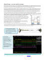
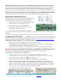
This is the schematic diagram from the Keil MCBSTM32E™ evaluation board. IC1 is a Texas Instruments CAN transceiver
which performs the conversion between the single-ended CAN controller CAN Tx and CAN Rx signals to the bi-directional
differential pair of the CAN bus called CAN Hi and CAN Lo (High and Low). This schematic is complete. The STM32
CAN I/O is TTL, CMOS and 5 volt tolerant, all at the same time making it exceptionally easy to design the interface.
This transceiver IC1 connects to the STM32 microprocessor IC2 which contains an integral CAN controller via two pins: D
(Driver input) and R (Receiver output). The corresponding nomenclature on the STM32 is CAN Rx and CAN Tx. CAN Tx
connects to D. CAN Rx connects to R. It is that simple. Some processors have multiple CAN controllers. These are usually
used in routers, gateways or to create more receiver FIFO memory for intentionally slowed down CPUs (for EMI reasons).
For general use a node normally needs only one controller. If it had at least two, it could talk to itself.
RS on IC1 (slope control) is used to adjust the rise and fall times of the output edges to limit EMI from the twisted pair.
Note R4, the 120 ohm termination resistor. This evaluation board is meant to be used with one other board as a small test
network. If this board is used as a node, and is not at one of the ends, this resistor should be removed and external resistors
used. P17 corresponds to a generally accepted standard for CAN on DB9 connectors. P17 Pin 7 is the CAN Hi bus line and
pin 6 is CAN Lo. TIP: If the CAN Hi and CAN Lo wires are reversed, the network will not operate.
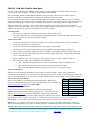
The MCBSTM32E board has one CAN controller. Since there must always be two CAN nodes for a network, you need
another board with a CAN node. Most CAN analyzers can act as the 2nd node. MCBSTM32C and STM32F4 Discovery
boards have two CAN nodes. Many other boards, including those from STMicroelectronics, contain two CAN nodes.
A Tiny Network without Transceiver ICs:
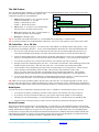
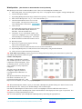
Sometimes you have a CAN equipped processor on a low cost board but it has no CAN transceiver chips. Here is a method
that can be used to create a small experimental network with such a board. There will be no noise immunity and you might
have to lower the speed….but many experimenters have made this work satisfactorily. Use a signal diode similar to 1N914
or 1N4148. Power supply diodes usually do not have a fast enough recovery time for CAN to function.
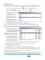
The processor on the STM32F4 Discovery board has two CAN controllers but
it has has no transceiver chips. How to install this on the Discovery board is
detailed in the section on “Running a CAN network…” on page 21.
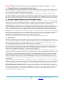
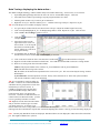
A three node CAN network. Uses two CAN nodes
on STM32F107 (Keil MCBSTM32C™) and
another on a STM32F407 Cortex-M4
(MCBSTM32F400™).
Termination is on the boards. This can be
disconnected on the MCBSTM32F400 with a
jumper. CAN Transceiver chips are used. These
boards can be connected to any Hi-Sped network.
This network works perfectly even though the
wires are a bit sloppy and are hardly a twisted pair.
This is because of the network’s small size and
robustness of CAN in general: even at 500 Kbps.
4
CAN: Controller Area Network Lab using ST STM32 Cortex-M processors.
Copyright © 2013 ARM Ltd. All rights reserved
www.keil.com