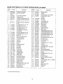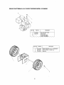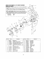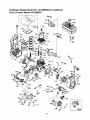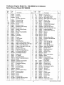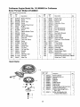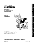
1
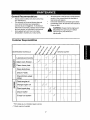
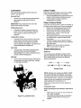
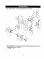
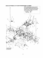
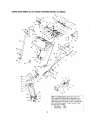
|
Owner's Manual
CRRFTSMRN
9 Horse Power
26" Two-Stage
MR
Wheel Drive
Snow Thrower
Model
No.
247.888520
CAUTION: Before using this product,
read this manual and follow all Safety
Rules and Operating Instructions.
Sears, Roebuck
Printed in USA.
And Co., Hoffman
Estates,
IL 60179,
U.S.A.
770-10057B
(10/98)
Content
Page
Content
Page
Warranty Information ......................................... 2
Service & Adjustment ......................................... 20
Safe Operation Practices ................................... 3
Off-Season Storage ........................................... 25
Assembly ...........................................................
6
Trouble-Shooting ............................................... 26
Operation ...........................................................
12
Accessories ....................................................... 27
Maintenance ...................................................... 17
Two -Year Warranty on Craftsman Snow Thrower
For two years from the date of purchase, when this Craftsman Snow Thrower is maintained, lubricated and tuned
up according to the instructions in the owner's manual, Sears will repair, free of charge, any defect in material
and workmanship.
If this Craftsman snow thrower is used for commercial or rental purposes, this warranty applies for only 30 days
from the date of purchase.
This warranty does not cover:
Expendable items which become worn during normal use, such as skid shoes, shave plate and spark
plugs.
Repairs necessary because of operator abuse or negligence, including bent crankshafts and the failure to
maintain the equipment according to the instructions contained in the owner's manual.
WARRANTY SERVICE IS AVAILABLE BY RETURNING THE CRAFTSMAN SNOW THROWER TO THE NEAREST
SEARS SERVICE CENTER/DEPARTMENT IN THE UNITED STATES.
This warranty applies only while this product is in use in the United States.
This warranty gives you specific legal rights and you may also have other rights which may vary from state to state.
SEARS, ROEBUCK AND CO., D/817WA, HOFFMAN ESTATES,IL 60179
Horsepower: ......................... 9
Engine Oil ............................. SAE 5W30 oil
Fuel Capacity: ....................... 1 gallon
Spark Plug: ........................... RJ-19LM
Engine: .................................. 143.999005
Model Number
247.888520
Serial Number ...........................................................
Date of Purchase ......................................................
Record both serial number and date of purchase and
keep in a safe place for future reference.
This symbol points out important safety instructions which, if not followed, could endanger the
personal safety and/or propertyof yourself and others. Read and follow all instructionsin this manual
before attempting to operate your snow thrower. Failure to complywith these instructionsmay result in
personal injury. When you see this symbol--heed its warning.
Your snow thrower was built to be operated according to the rules for safe operation in this
,_
DANGER: operator
result
in type
serious
injury.equipment,
If you violate
any of theseorrules,
maypart
cause
serious
manual. can
As with
any
of power
carelessness
erroryou
on the
of the
injury to yourself or others.
This unit is equipped with an internal combustion engine and should not be used on or near any unimproved
forest-covered, brush-covered or grass-covered land unless the engine's exhaust system is equipped with a
spark arrester meeting applicable local or state laws (if any). If a spark arrester is used, it should be
maintained in effective working order by the operator.
In the State of California the above is required by law (Section 4442 of the California Public Resources
Code). Other states may have similar laws. Federal laws apply on federal lands. A spark arrester for the
muffler is available through your nearest Sears Authorized Service Center (See the REPAIR PARTS section
of this manuaL.)
The engine exhaust from this product contains chemicals known to the state of California to cause cancer,
birth defects or other reproductive harm,
TRAINING
Read this owner's guide carefully in itsentirety before
attempting to assemble or operate this machine. Be
completely familiar with the controls and the proper
use of this machine before operating it. Keep this
manual in a safe place for future and regular
reference and for ordering replacement parts.
Never allow children under 14 years old to operate a
snow thrower. Children 14 years old and over should
only operate a snow thrower under close parental
supervision. Only persons well acquainted with these
rules of safe operation should be allowed to use your
snow thrower.
No one should operate this unit while intoxicated or
while taking medication that impairs the senses or
reactions.
Keep the area of operation clear of all persons,
especially small children and pets.
Exercise caution to avoid slipping or falling, especially
when operating in reverse.
gasoline cap securely and wipe off any spilled
gasoline before starting the engine as it may cause a
fire or explosion.
Use a grounded three wire plug-in for all units with
electric drive motors or electric starting motors.
Adjust collector housing height to clear gravel or
crushed rock surface.
Never attempt to make any adjustments while engine
is running (except where specifically recommended
by manufacturer).
Let engine and machine adjust to outdoor
temperature before starting to clear snow.
Always wear safety glasses or eye shields during
operation or while performing an adjustment or repair,
to protect eyes from foreign objects that may be
thrown from the machine in any direction.
OPERATION
Do not put hands or feet near or under rotatingparts.
Keep clear of discharge opening and auger at all
times.
Exercise extreme caution when operating on or
crossing gravel drives, walks, or roads. Stay alert for
hidden hazards or traffic.
Do not carry passengers.
After striking a foreign object, stop the engine, remove
wire from the spark plug and thoroughly inspect the
snow thrower for any damage. Repair the damage
before restarting and operating the snow thrower.
It the snow thrower starts to vibrate abnormally, stop
the engine and check immediately for the cause.
Vibration is generally a warning of trouble.
Stop the engine whenever you leave the operating
position, before unclogging the collector/impeller
housing or discharge guide and before making any
repairs, adjustments, or inspections. Never place your
PREPARATION
Thoroughly inspect the area where the equipment is
to be used and remove all door mats, sleds, boards,
wires and other foreign objects.
Do not operate equipment without wearing
adequate
outer garments for winter. Do not wear jewelry, long
scarfs or other loose clothing which could become
entangled in moving parts. Wear tootwear which will
improve footing on slippery surfaces.
Before working with gasoline, extinguish
all cigarettes
and other sources of ignition. Check the fuel before
starting the engine. Gasoline is an extremely
flammable fuel. Do not fill the gasoline tank indoors,
while the engine is running, or until engine has been
allowed to cool at least two minutes. Replace
3
I
hand in the discharge or collectoropenings. Use a
stickor wooden broom handle to unclog the
discharge opening.
Take all possible precautions when leaving the unit
unattended. Disengage the collector/impeller, stop
the engine and remove the key.
When cleaning, repairing, or inspecting, make certain
collector/impeller and alJmoving parts have stopped.
Disconnect spark plug wire and keep away from plug
to prevent accidental starting.
Do not run the engine indoors, except when starting it
and/or transporting the snow thrower in or out of
building. Open doors before starting the engine in that
case. Exhaust fumes are dangerous.
Do not clear snow across the face of slopes. Exercise
extreme caution when changing directionon slopes.
Do not attempt to clear steep slopes.
Never operate the snow thrower without guards,
pJates or other safety protection devices in place.
Never operate the snow thrower near glass
enclosure, automobiles, window wells, drop off, etc.,
without proper adjustments of snow thrower
discharge angle. Keep children and pets away.
Do not overload machine capacity by attempting to
clear snow at too fast a rate. Never operate the
machine at high transport speeds on slippery
surfaces. Look behind and use care when backing.
Never direct discharge at bystanders or allow anyone
in front of unit while throwing snow.
Disengage power to collector/impeller of the snow
thrower when transporting it or when the unit is not in use.
Use only attachments and accessories (such as
wheel weights, counter weights, cabs, etc.) approved
by the snow thrower manufacturer.
Never operate the snow thrower without good visibility
or right.Always be sure of your footing and keep a firm
hold on the handles. Walk, never run,
Muffler and engine become hot and can cause severe
burn injury. DO not touch the muffler or the engine
while starting or operating the snow thrower.
MAINTENANCE
AND STORAGE
Check shear bolts, engine mounting bolts, etc., at
frequent intervals for proper tightness, thus ensuring
that the equipment is in safe working condition.
Never store the machine with fuel in the fuel tank
inside a building where ignitionsources are present,
such as hot water heaters, space heaters, clothes
dryers and the like. Allow engine to cool before storing
in any enclosure,
Always refer to owner's guide instructions for
important details if the snow thrower is to be stored for
an extended period.
Run machine a few minutes after throwing snow to
prevent freeze-up of the collector/impeller.
Check clutch controls periodicallyto verify that these
engage and disengage properly and readjust if
necessary. Refer to Service and Adjustments section
page of this owner's guide.
YOUR RESPONSIBILITY
Restrict the use of thispower machine to persons who
read, understand and follow the warnings and
instructions in this manual and on the machine.
Following are representations of some of the safety labels on your Craftsman snowtbrower. Please follow the
instruction on these labels and maintain safety while using or servicing the equipment.
DAHGER
WARNING
]
4
Lay the hardware
pieces from the hardware
pack on the figure here and you will have automatically
sorted these
according to the steps of the assembly procedure described later. (Only one unit of each hardware
The number in parenthesis indicates the total number of the hardware needed in that group.)
has been shown per group.
L
A
Lock Wa,_her (4)
Hex B_
Hex Bolt
(6)
(_
j
Flutng(6_
(2)
5/16-16 x 1.75
m
__ 5/16-18 x .75
Chute Flange Keeper
__ 5/16-18 x .75
_
Cupped Washer
/____
--I
'_-It
I_
B
(3)
,
5116-18
Hex Bolt (2)
_
--_1
(4)
Bellevile Washer
Hex Nut (4)
( )
_
_[
1/4-20
:._
:_ _._
_L ""
5/16-16 x 1.50
5/16-18
1.50
¢ irrlage
Carriage
j
%.
,,/
_l
Flange
-_
Bracket
-_1
InOtcth°lWn
Bolt (4)
Bolt
size)
G
_1
Chute
Hairpin
\
Clip (1)
_
_1
' '_1
Flat
---II
Washer
(2)At
.a,rp_
/
c,p(1)
D
_.
_
Hairpin Clip (21
0,,F,
_
12 ©
Wat'a_WaehS/_
_2)
C)
i
Fe(rlr) e
,,a,
em,
Replacement
'_
Part
Shear Bolt (2)
5/16-18x
1,5
_//
Flat Weld Nut (2)
Handle Panel
Rear
•
Left
Handles
• _L,J
Ri
"_i"wo-Piece
Chute Crank
Discharge Chute
Front
4"
_,? ._
/
/
,i/
W
//
Rod
IMPORTANT: This unit is shipped with engine oil in
the engine, but without gasoline. After assembly, see
OPERATION section of this manual for fuel selection
and fill-up.
NOTE: To determine right and left hand sides of your
snow thrower, stand behind the unit with the engine
farthest away from you. See inset•
Your snow thrower has been completely assembled
at the factory, except the handle and the handle
panel, the discharge chute assembly, the chute crank
assembly and the shift rod• These parts are shipped
loose in the carton.
Removing From Carton
•
•
•
Cut the corners of the carton and lay the sides
flat on the ground• Remove all packing inserts.
Remove all loose parts. For a complete list of
the loose parts, refer to the following section•
Move the snow thrower out of the carton.
Make certain all parts and literature have been
removed before discarding the carton.
Loose Parts
(See Figure 1.)
a. Handle Panel and Chute Assembly
b.
Right Hand Handle
Figure 1
c. Lett Hand Handle
d, Two-piece Chute Crank Assembly
e. Shift Rod
f. Hardware Pack
Assembly Tips: For easier assembly purposes,
remove the chute from the carton and lay it on top of
the engine. Do not unwrap the chute tillyou have
installedthe handle panel and the clutch cables.
Tools Required
1,
2,
3.
4.
i_
1/2", 7/16", 3/8" wrenches or a set of adjustable
wrenches
Set of pliers
Set of philips head screw drivers
Funnelto fill up gasoline
is disconnected and
moved
WARNING:Make
certain
the away
sparkfrom
plugthe
wire
spark plug before assembling the snow thrower.
Attaching
•
Handle
Assembly
Stretch out control cables and place on the floor•
Place the right handle in position with the flat
side against the snow thrower• You can identify
the right handle by the traction drive control label
on it and the left handle by the auger clutch
control label on it.
Secure bottom hole in the handle to the snow
thrower using 5/16 x0.75" hex bolt and lock
washer from the hardware pack (group A on
page 5 ). Do not tighten at this time. See Figure 2.
Attach the handle panel to the handle with two
carriage bolts, cupped washers (cupped side
against the handle panel) and hex nuts on each
side. See Figure 3. You will find these fasteners
in the hardware pack (group B on page 5). Align
the contour of the carriage bolt head with the
handle.
Lock Washer &
Hex Bolt (1-3/4")
Attaching
Right Handle
Handle
Tab
_[Washer &
Hex Bolt (3/4")
Figure 2
Place a handle tab, included in the hardware
pack (group A on page 5), over the upper hole in
handle so that the contour of the handle tab
matches that of the handle. See Figure 2.
Secure handle tab to the snow thrower using
hex bolt (5/16 x 1.75" long) and lock washer
from the same group in the hardware pack. Do
not tighten at this time.
Attach the left handle in the same manner. Do
not tighten at this time.
Place the handle panel in position between the
handles so the ends of the curved part of the
handles go through the slots in the handle panel.
While placing the handle panel, make sure to
route chute and chute cable between the
handles underneath the panel keeping the cable
on top of the engine. Align the holes in the
handle with the holes on two sides of the handle
panel. See Figure 3.
Chute
Hex
Nut
\
Chute
'_e
x
Bolt
Flange
Keeper
Figure 4
After assembling all three chute flange keepers,
tighten, then back off 1/4 turn to allow easier
movement of the chute. Use (2) 7/16" wrenches.
Right Handle
Handle Panel
Hex Bolt
and Flange
Nut
Chute
Place the chute assembly over the chute
opening with the chute facingfront of the unit.
NOTE: Make sure that the chute cables are
straightened while assembling the chute.
•
Place the chute flange keeper (flat side down)
beneath lip of chute assembly as shown in
Figure 4.You will find the chute flange keepers in
group E of the hardware pack.
•
Insert 1/4-20 hex bolt and flange nut from group
E up through chute flange keeper and chute
assembly as shown in Figure 4. Do not tighten at
this time. Rotate chute to install all the flange
keepers.
Attaching Chute Crank
\
n Holes
CarriageBolt,
and HexNut
Figure 3
•
On the leftside of the handle panel, place the
upper chute crank bracket on to the inside of the
handle panel support. See Figure5. You willfind
this bracket and associated hardware in group F
of hardware pack
Insert hex bolt through the upper chute crank
bracket, handle panel support, and upper left
handle. Secure the bracket using cupped
washer and hex nut. Make sure that the cupped
side of the washer is set against the handle.
Adjust the chute bracket so that the spiral on the
chute crank fully engages the teeth on the chute
assembly.
Slide the upper chute crank through the plastic
bushing in the upper chute crank bracket and
then into the lower chute crank. See Figure 8.
Align the holes on the two pieces of the chute
crank, and secure with hairpin clip from group C
of the hardware pack.
ook
Tilt
Chute
Cables
Supped
Upper
Chute
Crank
_,
j_
Chute Crank
Bracket
_ Bracket
;
_
\\
.Upperl
Chute
Crank
::,
Figure 5
You may have to loosen the carriage boltsand
hex lock nutswhich secure the lower chute
crank bracket to the extension on the left side of
the chute assembly. See Figure 6.
\
Lower Chute
" _\_Crank
Figure 8
•
Crank Bracket
•
Hex L_cEk
Nut'
Figure 6
Fully rotate the chute, using the chute crank, to
make sure that it moves freely.
Using a wrench, tighten the hex bolt and the hex
nut on the upper chute crank bracket.
Slip the cables that run from the handle panel to
the chute into the cable guide located on top of
the engine. See Figure 9.
Cable Guide_/_
Place one 3/8 ID flat washer (from group G of
the hardware pack) on the end of the chute
crank, then insert the end of the crank intothe
eye hole inthe plasticbushing in the chute crank
bracket. See Figure 7.
HairpinClip
Plastic Bushing
Chute Crank
Figure 9
=
Lower Chute J
Crank Bracket_
Tighten all loose hardware on the handle
assembly in the following order-- first the four
hex bolts at the bottom of the handle, then the
carriage bolts and lastly the hex bolts on the rear
of the handle panel.
"FlatWasher
Attaching
Figure 7
Clutch Cables
The clutchcontrol cables are attached to the snow
thrower. For shippingpurposes, if the cables are
attached to the top of the engine with cable ties, cut
the cable ties now. The Z ends of the clutchcables
are hooked into the clutch grips on each handle.
Place the other 3/8 ID flat washer (from the
same group of hardware) on the end of the
chute crank and insert hairpin clip intoeye hole
at the end of the chute crank. See Figure 7.
8
Ensurethereisa hexjamnutthreaded
allthe
in the hole in the shift lever. For proper
positioning of the ferrule and the associated
hardware, see Figure 11.
way up the threaded portion of the Z fitting;
extras are supplied in the hardware pack. See
Figure 10.
Place the clutch grip in the raised (up) position.
Shift
Lever
Z Fitting
Outer
of cut-out
\
Chute Distance
Control
Drive
Clutch
Auger
Nut
Upper
Hex Jam
Nut
"_
Flat
Washer
Shift
Lever
'
Clip
Rod
_(Vi_ii_i_theont
rol panel)
Hair
Clip
Figure 10
Figure 11
Swing the left auger cable up making sure the
cable is routed correctly in the cable roller
guides located at the lower rear of the unit.
Hold the end of the cable at the barrel so the
ferrule turns freely without twisting the cable.
Thread the ferrule on to the Z fitting. You may
have to pull on the cable slightly to relieve
tension. Keep the ferrule turning without twisting
the cable.
You will reach correct adjustment when there is
minimal slack in the cable but it is not tight. Hold
the flats on the ferrule with pliers and tighten the
jam nut against the ferrule. CAUTION: Cables will
become loose if you do not tighten the jam nut.
A
NOTE: You may have to pull the shift lever out of the
sixth speed position and move it towards the fifth
speed position until the ferrule slides into the hole
without force.
Secure the ferrule to the shift lever with another
5/16 flat washer and hairpin clip from group D of
the hardware pack. See Figure 11.
Make certain to check for correct adjustment of
the shift rod as instructed in the Adjustment
section before operating the snow thrower.
Attaching Turn Triggers
•
WARNING: There must not be any tension
on either clutch cable with the drive or auger
clutch grip in the disengaged (up) position.
These clutches are a safety feature. Do not
•
override their function.
Attaching
•
Assembly
Shift Rod
Place the shift lever in the sixth (6) speed.
Place the bent end of the shift rod into the hole in
the shift arm assembly. See Figure 11. Secure
with 5/16 flat washer and hairpin clip from group D
of the hardware pack.
Thread ferrule (included in group D) from the
right side onto the other end of the shift rod till it
lines up with the upper hole in the shift lever
(beneath the handle panel). While aligning the
ferrule, push down on the shift rod and the shift
arm assembly as far as it will go.
Once the ferrule slides into the hole, turn it
counter-clockwise one more full turn and insert it
Check and make sure that the right hand trigger
cable is routed in front of the traction drive cable.
Feed the trigger cable up through the outer side of
the slot in the handle panel. Do not feed the cable
through the same side of the slot as the Z fitting.
Place the cable barrel fitting into the hole in the
trigger. You can find the triggers and associated
hardware in group H of the hardware pack. See
Figure 12.
Trigger
Assembly
Inner Cable _'N_
/
/
Trigger
Housing
Slot
Cable snaps in at
this end
Figure 12
9
•
Pull on the cable and rotate it around the bottom
of the trigger, with the inner cable in the slot, until
the cable end can be pushed into the trigger
housing and snapped tight. See Figure 12.
Plugwire into the alternator
lead wire under the
fuel tank. See Figure 15.
jTrigger
Note: When the cable is installed correctly, you
should not be able to pull the cable out of the trigger
housing.
•
Place the right turn trigger in position
underneath the right handle. Secure with screw
and weld nut from group H of the hardware
pack. See Figure 13. You will need a phillips
screwdriver for tightening the screw. Repeat on
left side.
Cable
" ,,_Handle" I
Alternatori
Lead
Secure with screw
WeldNut
Figure 15
IMPORTANT: Assemble your snow thrower, then
check the adjustments as instructed and make any
final adjustments necessary before operating the unit.
Failure to follow the instructions may cause damage
to the snow thrower.
Trigger
Slot
Final Adjustments
i rl er
Ca_le
Auger Control
Figure 13
To check the adjustment of the auger control,
push forward the left hand clutch grip until the
rubber bumper is compressed. There should be
slack in the clutch cable.
Release the clutch grip. The cable should be
straight. Make certain you can depress the
auger control gnp against the left handle
completely.
If adjustment is necessary, loosen the hex jam
nut and thread the cable in (for less slack) or out
(for more slack).
Recheck the adjustment. Tighten the jam nut
against the cable when correct adjustment is
reached.
Secure the right turn trigger cable to the right
lower handle using cable tie provided in the
hardware pack. Make sure not to wrap the drive
cable. See Figure 14.
CableTie_
Trigger Cable
Traction Drive Clutch and Shift Lever
Tip the snow thrower forward so that it rests on
the auger housing.
Move the shift lever all the way forward to sixth
(6) position.
•
With the tractiondrive lever released, spin the
snow thrower wheels by hand. The wheels
should turn; however, you may feel some
resistance.
Engage the tractiondrive clutchgrip. The
wheels should no longerturn.
Now release the tractiondrive clutch grip,and
spin the wheels again.
•
Move the shift lever back to the fast reverse
position,then all the way forward again. There
Figure 14
Secure the left turn trigger cable to the lower
handle using the other cable tie. Make sure to
route the cable tie below the auger drive cable
so that when the trigger cable is secured by the
cable tie, the auger drive cable is left outside the
cable tie. Trim excess ends from each cable tie.
NOTE: The right side cable tie must be used to keep
cable from coming in contact with the moving shift
arm from the transmission.
Lamp Wiring
•
Wrap the wire from the lamp down the right
handle as shown in Figure 15.
10
should be no resistance in the shift lever, and the
wheels should turn.
If you face resistance when moving the shift
lever or the snow thrower wheels stop when they
should not, loosen the lock nut on the traction
drive cable and unthread the cable one turn.
If the wheels can still be turned when you
engage the traction drive clutch grip, loosen the
lock nut on the traction drive cable and thread
the cable in one turn.
Adjust skid shoes by loosening the four hex nuts
and carriage bolts and moving skid shoes to
desired position.
Make certain the entire bottom surface of skid
shoe is against the ground to avoid uneven wear
on the skid shoes.
Tighten nuts and bolts securely.
Recheck the adjustment and repeat adjustment
as necessary. Tighten the lock nut to secure the
cable when correct adjustment is reached.
NOTE: If you are not sure that you have reached
correct adjustment, refer to the Adjustment section on
page 20.
--Skid Shoe
Remove these hardware
Skid Shoe
The space between the shave plate and the ground
can be adjusted. For close snow removal, place skid
shoes in the low position. Use middle or high
position when area to be cleared is uneven.
to adjust skid shoe
Figure 16
If for some reason, you have to operate the snow
thrower on gravel, keep the skid shoe in the
highest position for maximum clearance between
the ground and the shave plate.
NOTE: It is not recommended that you operate this
snow thrower on gravel as loose gravel can be easily
picked up and thrown by the auger causing an injury
or damage to the snow thrower.
Tire Pressure (Pneumatic Tires)
If for some reason, you have to operate the
snow thrower on gravel, keep the skid shoe in
the highest position for maximum clearance
between the ground and the shave plate.
The tires are over-inflated for shipping purposes.
Check tire pressure and reduce to 15 to 20 psi.
NOTE: If the tire pressure is not equal in both tires, the
unit may pull to one side or the other.
11
Knowing Your Snow Thrower
Read this owner's manual and safety rules before operating your snow thrower. Compare
with your snow thrower to familiarize yourself with the location of various controls and
adjustments. Save this manual for future reference.
The operation of any snow thrower can result in foreign objects being thrown into the eyes,
which can result in severe eye damage. Always wear safety glasses for operating the snow
thrower, or while performing any adjustments or repairs on it.
Oil
Traction Drive
Auger
\
Choke
Control_
Shift
Chute
Lever Distance
Fuel
Spark Fill
Control
Lever
Fuel i
Tank l
Chute Crank
/
/
/
Key
Starter
Handle
Primer
Right
Turn
Throttle
\,
Trigger
DischargeChute
Recoil
Starter
/
/
Au_]er
Skid Shoe
Figure 17
Meets ANSI Safety Standards
Sears snow throwers conform to the safety standards B71.3 of the American National Standards Institute (ANSI).
12
Operating Controls
Chute Distance
(See Figure 17.)
The distance that snow is thrown can be adjusted by
adjusting the angle of the chute assembly. Move the
chute distance control forward to decrease the
distance, toward the rear to increase the distance.
Chute Crank
The chute crank is located on the left hand side of the
snow thrower. To change the direction in which snow
is thrown, turn chute crank as follows:
turn clockwise to discharge to the left;
turn counterclockwise to discharge to the right.
Control
To Stop The Snow Thrower
To stop the wheels, release the traction drive
lever of the snow thrower.
To stop throwing snow, release the auger drive
lever.
To stop the engine, push the throttle control
lever to OFF and pull out the ignition key. Do not
turn key.
Throttle Control
The throttle control is located on the engine. It
regulates the speed of the engine.
Safety Ignition Switch
Before Starting Engine
The ignition key must be inserted into the switch for
the unit to start. Remove the ignition key when the
snow thrower is not in use.
Fill Gas
&
Left And Right Turn Trigger
The left and right turn triggers are located on the
underside of the handles and are used to assist in
steering your snow thrower. Squeeze the right turn
trigger when turning right, squeeze the left turn trigger
when turning left. Operate your snow thrower in open
areas until you become familiar with these controls.
WARNING: Gasoline is flammable and caution must be used when handling or storing it.
Do not fill fuel tank while the snow thrower is
running, when it is hot or when it is in an
enclosed area.
Keep your snow thrower away from any
open flame or an electrical spark and do not
smoke while filling the fuel tank.
Shift Lever
Never fill the fuel tank completely. Fill the
tank to within 1/4"-1/2" from the top to
provide space for expansion of fuel.
The shift lever is located in the center of the handle
panel. It may be moved into one of eight positions:
a. Forward--one of six speeds; position one (1)
isthe slowest and position six (6) is the
fastest.
b. Reverse--two reverse (R) speeds; R2 is
faster.
Use the shift lever to determine ground speed. Do not
shift to different speed while the unit is moving.
Always fill the fuel tank outdoors and use a
funnel or spout to prevent spilling.
Make sure to wipe off any spilled fuel before
starting the engine.
Store gasoline in a clean, approved container
and keep the cap in place on the container.
Make sure that the container from which you
pour the gasoline is clean and free from rust or
other foreign particles.
Fill fuel tank with clean, fresh, unleaded grade
automotive gasoline.
At the end of the job, empty the fuel tank if the
snow thrower is not going to be used for 30 days
or longer. See storage instructions on of this
manual.
Auger Control
The auger control is located on the left handle.
Squeeze the auger control against the handle to
engage the augers; release to disengage the augers.
(Traction drive control must also be released.)
Traction Drive Control
The traction drive control is located on the right
handle. Squeeze the traction drive control to engage
the wheel drive; release to stop.
This same lever also locks the auger control so
that you can turnthe chute crank without interrupting
the snow throwing process. If the auger controlis
engaged with the tractiondrive controlengaged, you
can release the auger control(on the lefthandle) and
the augers willremain engaged. Release the traction
drive controlto stop both the augers and the wheel
drive. (Auger controlmust also be released).
CAUTION: Experience indicates that alcohol blended
fuels (called gasohol) or those using ethanol or methanol can attract moisture which leads to separation
and formation of acids during storage.
Acidic gas can damage the fuel system of an engine
while in storage.
To avoid engine problems, the fuel system should be
emptied before storage for 30 days or longer. Drain the
gas tank, start the engine and let it run until the fuel
13
linesandcarburetor
areempty.
Usefreshfuelnextseason.Seestorage
Instructions
foradditional
information.
Neveruseengineorcarburetor
cleanerproducts
in
thefueltankorpermanent
damage
mayoccur.
augers) with the clutch grips disengaged, shut the
engine off immediately. Readjust as instructed in the
"Final Adjustments" section of the Assembly
Instructions.
To Start Engine
A
properly
grounded
at all times
avoidbethe
WARNING:
The electric
startertomust
possibility of electric shock which may be
injurious to the operator.
Determine whether your house wiring is a threewire grounded system. Ask a licensed
electrician if you are not certain.
WARNING: Be sure no one other than
the operator is standing near the snow
thrower while starting or operating. Do not
operate this snow thrower unless the
discharge chute assembly has been
properly installed and is secured.
net
a three-wire
grounded
do not isuse
WARNING:
If your
house system,
wiring system
this electdc starter under any conditions.
A. Electric Starter
Connect spark
plug wire
If your house wiring system is grounded and a
three-hole receptacle is not available at the point
the snow thrower starter will normally be used,
one should be installed by a licensed electrician.
When connecting the power cord, always
connect cord to starter on engine first, then plug
the other end into a three-hole grounded
receptacle.
When disconnecting the power cord, always
unplug the end from the three-hole, grounded
receptacle first.
For illustration of starting instructions, see Figure 18.
•
Attach spark plug wire to spark plug.
•
Make sure that the auger drive and the traction
drive levers are in the disengaged RELEASED
position.
•
Move throttle control lever to FAST position.
Remove the keys from the plastic bag. Push key
into the ignition slot. Make sure it snaps into
place. Do not tum key. Keep the second key in a
safe place.
Rotate the choke knob to FULL choke position.
•
Connect the power cord to the switch box on the
engine.
•
Plug the other end of the power cord into a
three-hole, grounded 120 volt A.C. receptacle.
Insert key.
Move
"_"
Prime
_¢_hoke
_
.
ConnectbUtton
cord
t_OV_ll
_
_
_
.
Recoil
_" starter
Figure 18
(For location of all the engine controls referred to in
this section, see Figure 17 inset.)
Before starting, make sure that the engine has sufficient oil. The snow thrower engine is equipped with a
120 volt A.C. electric starter and recoil starter. The
electric starter is equipped with a three-wire power
cord and plug and is designed to operate on 120 volt
AC household current. Follow all instructionscarefully
Cold Start
starting
the engine
electric
starter.
WARNING:
Do notwith
use an
primer
while
NOTE: If the unit shows any sign of motion (drive or
_
i_
3
Starting Instructions
at a glance
Throttle
control
Ignition
Key
Choke
Power
Co_
Connect Release
Move to
FAST
Push to
snap in
Move to
FULL
Connect
to source
_,onnect Release
Move to
FAST
Push to
snap in
Move to
FULL
Snow
Thrower
Spark
Plug
wire
Electric
Starter
Recoil
Starter
Drive
Levers
14
Primer
Prime
Starter
After starting
Push
button
1. Release button
2. Move Choke to Off
3. Disconnect cord
Pull
handle
1. Release handle
2. Move Choke to Off.
•
•
•
•
Push down on the starter button until the engine
starts. Do not crank for more than 10 seconds at
a time. This electric starter is thermally
protected. If overheated, it will stop
automatically and can be restarted only when it
has cooled to a safe temperature (a wait of
about 5 to 10 minutes is required).
When the engine starts, release the starter
button and slowly rotate the choke to OFF
position. If the engine falters, rotate the choke to
FULL and then gradually to OFF.
Disconnect the power cord from the receptacle
first and then from the switch box on the engine.
Allow the engine to warm up for a few minutes
because the engine will not develop full power
until it reaches operating temperature.
Operate the engine at full throttle (FAST) when
throwing snow.
Pull as much rope out of the starter as possible.
Release the starter handle and let it snap back
against the starter.
If the engine still falls to start, repeat the first two
steps. If continued attempts do not free starter,
follow the electric starter procedures to start.
Avoid possible freezing of recoil starter and the
engine controls.
•
Operating
To Engage Drive
With the engine running near top speed, move
shift lever to one of six FORWARD positions or
two REVERSE positions. Select a speed
appropriate for the snow conditions that exist.
Use slower speeds until you are familiar with the
operation of the snow thrower.
Squeeze the traction drive clutch grip against
the right handle and the snow thrower will move.
Release it and the drive motion will stop.
Warm Start
If restarting a warm engine after a shut down,
rotate choke to OFF instead of FULL and press
the starter button.
To Engage Augers
•
To engage the augers and start snow throwing,
squeeze the left hand auger clutch grip against
the left handle. Release to stop augers.
While the auger control is engaged, squeeze the
traction drive control to move, release to stop.
Do not shift speeds while the drive is engaged.
NOTE: This same lever also locks the auger control
so you can turn the chute crank without interrupting
the snow throwing process.
Release the auger control; the interlock
mechanism should keep the auger control
engaged until the traction drive control is
released.
Release the traction drive control to stop both
the augers and the wheeil drive.
B. Recoil Starter
Make sure that the engine has sufficient oil and the
auger drive and the traction drive levers are released.
•
Move throttle control to FAST position.
Push key into the ignition slot so that it snaps
into place. Do not turn key. Remove plastic bag
and keep the second key in a safe place.
Rotate choke control to FULL choke position.
Push the primer button while covering the vent
hole. Remove your finger from the primer between
primes. Do not prime if temperature is above
•
•
Snow Thrower
50o P; prime two times between 500 F and 15° F;
and prime four times below 15o F.
Pull the starter handle rapidly. Do not allow the
handle to snap back, but allow it to rewind slowly
while keeping a firm hold on the starter handle.
As the engine warms up and begins to operate
evenly, rotate the choke knob slowly to OFF
position. If the engine falters, return to FULL
choke, then slowly move to OFF choke position.
Allow the engine to warm up for a few minutes
because the engine will not develop full power
until it reaches operating temperature.
Operate the engine at full throttle (FAST) when
throwing snow.
,_,
must be released.
WARNING: To stop the auger, both levers
To Throw
i_
Snow
foreign objects. Remove, if any.
CAUTION: Check the area to be cleared for
Start the engine following Starting instructions.
Rotate the discharge chute to the desired
direction, away from bystanders and/or
buildings. Move the chute distance control
forward or backward to adjust the distance the
snow is to be thrown.
Select the speed according to snow condition.
Warm Start
If restarting a warm engine after a temporary
shut down, rotate choke to OFF instead of FULL
and do notprime. Press the starter button.
Frozen Recoil Starter
If the starter is frozen and will not turn the engine,
proceed as follows:
,_
15
without first releasing the drive clutch.
CAUTION: Never move the shift lever
Engage the auger control and traction drive
control levers following instructions above.
The interlock feature will allow you to remove
your left hand from the auger control lever.
When clearing the first pass through the snow,
control the traction speed of the snow thrower
according to the depth and condition of snow.
To turn the unit left, squeeze left trigger; to turn
right, squeeze right trigger.
On each succeeding pass, readjust the chute
deflector to the desired position and slightly
overlap the previously cleared path.
After the area is cleared, stop the snow thrower
following instructions given below.
If for some reason, you have to operate the snow
thrower on gravel, keep the skid shoe in the
highest position for maximum clearance between
the ground and the shave plate.
Clean the snow thrower thoroughly after each use.
Before
Stopping
•
Run engine for a few minutes to help dry off any
moisture on engine.
•
To avoid possible freeze-up of the starter, follow
these steps:
Recoil Starter
a. With the engine running, pullthe starter rope
with a rapid, continuous full arm strokethree
or four times.
Electric Starter
a. Connect power cord to switch box, then to
120 Volt AC receptacle.
b. While the engine is running,push the starter
button and spin the starter for several
seconds.
c. Disconnect power cord from the receptacle
first, then from the snow thrower.
NOTE; The unusual sound from pulling the starter
rope in the case of the recoil starter, or from spinning
the starter in the case of the electric starter, will not
harm the engine.
Operating Tips
NOTE: Allow the engine to warm up for a few minutes
as the engine will not develop full power until it
reaches operating temperature.
surrounding
areas
may exceed
150 ° F.and
Avoid
Warning: The
temperature
of muffler
these areas.
For most efficient snow removal, remove snow
immediately after it falls.
•
Discharge snow downwind whenever possible.
Slightly overlap each previous swath.
•
Set the skid shoes 1/4" below the scraper bar for
normal usage. The skid shoes may be adjusted
upward for hard-packed snow.
NOTE: It is not recommended that you operate this
snow thrower on gravel as loose gravel can be easily
picked up and thrown l_y the auger causing an injury or
damage to the snow thrower.
To Stop The Snow Thrower
•
16
To stop the wheel, release the tractiondrive lever
on the snow thrower.
To stop throwingsnow,releaseaugerdrivelever.
To stop the engine, push throttlecontrollever to
OFF and pull out the ignitionkey. Do not turnkey.
General Recommendations
All adjustments in the Service and Adjustments
section of this manual should be checked at
least once each season.
Follow the maintenance schedule given below.
Periodically check all fasteners and make sure
these are tight.
Always observe safety rules when performing
any maintenance.
The warranty on this snow thrower does net
cover items that have been subjected to
operator abuse or negligence. To receive full
value from the warranty, operatormust maintain
the snow thrower as instructedin this manual.
Some adjustments willhave to be made
periodically to maintain your unit properly.
disconnect
sparkstop
plugthe
wire
beforeand
WARNING; the
Always
engine
performing any maintenance or
adjustments.
Customer Responsibilities
MAINTENANCE SCHEDULE
o
_
_.
_
Lubricate pivot points
_
Clean snow thrower
0
Clean shave plate
Clean skid shoes
Check
V-belts
Check friction wheel
rubber
,,,
z
Z
LU
Check engine oil
Change engine oii
Check spark plug
Check muffler
Empty fuel system
* Fill in dates as you complete regular service
,_ Check; service if needed
17
_
__o SERVICE DATES
i
Lubrication
Check
For a view of the lubricationpoints on the snow
thrower, see Figure 19.
Follow the instructionsbelow to check the condition
of the drive belts every 50 hours of operation.
•
Remove the plastic belt cover on the front of the
engine by removing two self-tapping screws.
Visually inspect for frayed, cracked, or
excessively worn out belts.
Sprocket Shaft
Lubricatethe sprocket shaft with grease at least
once a season or after every 25 hours of
operation.
IMPORTANT: Keep all grease and oil off of the
friction wheel and the drive plate.
Shifting Mechanism
Lubricate the shifting mechanism and pivot
points on the shift rod with engine oil at least
once a season or after every 25 hours of
operation.
Check
•
•
Gear Case
Wheel
Also engage traction drive control and check if
the friction wheel is making contact with the
friction plate.
If it does not make contact, adjust the traction
drive cable following instructions and. Recheck
the friction wheel.
Replace friction wheel rubber if necessary.
Refer to instructions on page 23.
Engine Maintenance
The gear case is lubricated with grease at the
factory and does not require checking. If
disassembled for any reason, lubricate with two
ounces of Shell Alvania grease.
Engine Oil
Only use high quality detergent oil rated with API
service classification SF, SG or SH. Select the oil's
SAE viscosity grade according to the expected
operating temperature.
Bearings
•
Friction
Follow the instructions below to check the condition of
the friction wheel rubber every 25 hours of operation.
Remove the six self-tapping screws from the
frame cover underneath the snow thrower.
Visually inspect the friction wheel rubber for
excessive wear, cracks, or loose fit on the
friction wheel drive hub.
Traction Drive Control
Lubricate cams on the ends of the control rods
which interlock the traction drive and auger
controls at least once a season or every 25
hours of operation with grease. The cams can be
accessed beneath the handle panel.
V-belts
Once a season lubricate the auger bearings and
the bearings on the side of the frame with light
oil. See lube chart below.
colder -_--32
5W30 _
° _
I
I
warmer
_
SAE30
Viscosity Chart
NOTE: Although multi-viscosity oils (5W30, 10W30
etc.) improve starting in cold weather, these multiviscosity oils will result in increased oil consumption
when used above 32°F. Check your snow thrower's
engine oil level more frequently to avoid possible
engine damage from running low on oil.
Refer to the viscosity chart for proper selection of
engine oil
Checking
Oil Level
Before operating
level.
the snow thrower, check the oil
With engine on level ground, the oil must be to
FULL mark on dipstick.
Stop engine and wait several minutes before
checking oil level. Remove oil fill cap and
dipstick.
Figure 19: Lubrication Chart
18
Spark Plug
Wipe dipstick clean, insert it into oil fill hole and
tighten securely.
Remove dipstick and check. If oil is not up to the
FULL mark on dipstick, add 5W30 oil.
•
•
Clean area around the spark plug base.
Remove and inspect the spark plug.
Replace the spark plug ifelectrodes are pitted,
burned, or the porcelain is cracked. See Figure 20.
Clean the spark plug and reset the gap to 0.030"
at least once a season or every 50 hours of
operation. See Figure 20.
•
Spark plug replacement is recommended at the
start of each season. Refer to engine parts list
for correct spark plug type.
NOTE: Do not sandblast spark plug. Spark plug
should be cleaned by scraping or wire brushing and
washing with a commercial solvent.
Changing Oil
Change engine oil after first two hours of operation
and every 25 hours thereafter.
In order to change the oil, you will have to first drain
the spent engine oil from the engine and then refill
with fresh oil.
Drain oil while engine is warm. Remove oil drain
cap located at the bottom of the recoil starter of
the engine. Catch oil in a suitable container.
•
When engine is drained of all oil, replace drain
plug securely.
Remove the dipstick from the oil fill plug. For
location of the oil fill plug, see. Pour fresh oil
slowly through the plug. Replace dipstick.
Check and make sure that the level of oil is up to
the FULL mark on the dipstick.
Electrodes
,030"
Gap
WARNING:
of muffler
and
nearby areas Temperature
may exceed 150
° F(65°C).
Avoid these areas_
Porcelain
Figure 20
19
A
WARNING: Always stop the engine, disconnect spark plug wire and move it away
from the spark plug before performing any
adjustments or repairs.
and the drive plate in all positions of the shift
lever.
With the traction drive clutch engaged, the
friction wheel must contact the drive plate
(shown in Figure 30).
If adjustment is necessary, loosen the jam nut
on the traction drive cable and thread the cable
in or out as necessary. See Figure 21. Tighten
the jam nut to secure the cable when correct
adjustment is reached. Reassemble the frame
cover.
Never attempt to clean the chute or make
any adjustments while the engine is running.
Adjustments
WARNING: Never attempt to clean chute or make
any adjustments while engine is running.
Chute Assembly
NOTE: If you placed plastic under the gas cap, be
certain to remove it.
The distance that snow is thrown can be adjusted by
adjusting the angle of the chute assembly. Refer to
the Control section of this manual.
The remote chute control cables have been preadjusted at the factory. Move the remote chute
lever on the control panel back and forward to
adjust angle of the chute asssembly.
Auger Clutch
To adjust the auger clutch, refer to Final Adjustment
section of Set-Up Instructions.
Skid Shoe
The space between the shave plate and the ground
can be adjusted. For close snow removal, place skid
shoes in the low position. Use middle or high position
when area to be cleared is uneven.
Adjust skid shoes by loosening the four hex nuts
and carriage bolts and moving skid shoes to
desired position.
•
Make certain the entire bottom surface of skid
shoe is against the ground to avoid uneven wear
on the skid shoes.
•
Retighten nuts and bolts securely.
Handle
Panel
Hex Jam
(Thread
nut here) __.
Clip
Cable is straight
but i_ol lighl
NOTE: It is not recommended that you operate this
snow thrower on gravel as loose gravel can be easily
picked up and thrown by the auger causing an injury
or damage to the snow thrower.
•
If for some reason, you have to operate the
snow thrower on gravel, keep the skid shoe in
the highest position for maximum clearance
between the ground and the shave plate.
_ Shift
Rod
(Viewed from under the handle panel)
Figure 21
Shift Rod
To adjust the shift rod, proceed as follows.
Remove the hairpin clip and flat washer from the
shift handle under the handle panel.
Place shift lever in sixth (6) position or fastest
forward speed.
Push shift arm assembly down as far as it will go.
•
Rotate the ferrule up or down on the shift rod as
necessary until the ferrule lines up with the
upper hole in the shift lever. See Figure 21.
Insert ferrule from the left side of the
snowthrower into the upper hole in shift lever.
Reinstall the hairpin clip and the washer.
Traction Drive Clutch
Refer to the Final Adjustment section of the Set-Up
Instructions to adjust the traction drive clutch. To
check the adjustment, proceed as follows:
With the snow thrower tipped forward (be
certain to drain the gasoline or place plastic film
under the gas cap if the snow thrower has
already been operated), remove the frame cover
underneath the snow thrower by removing six
self-tapping screws.
With the traction drive clutch released, there
must be clearance between the friction wheel
,_
2O
before operating the snow thrower.
CAUTION: Check for correct adjustment
Carburetor
heads of the carriage bolts are to the inside of
the housing. Reinstall skid shoe. Tighten
securely.
WARNING: If any adjustments are made
to the engine while the engine is running
(e.g carburetor), keep clear of all
moving parts. Be careful of heated
surfaces and mufflers.
Replacing Belt
,_
Minor carburetor adjustments may be required to
compensate for differences in fuel temperature,
altitude and load.
wire
from theDisconnect
spark plug the
andspark
ground.
WARNING:
plug
Auger Belts
•
Service
Remove the plasticbelt cover on the front of the
engine by removing the two self-tapping screws.
See Figure 23.
Augers
Self-Tapping Screw
The augers are secured to the spiral shaft with two
shear bolts and hex lock nuts. If you hit a foreign
object or ice jam, the snow thrower is designed so
that the bolts will shear. See Figure 22. Lock nuts
cannot be threaded onto a bolt by hand. This type of
nut is used where vibration occurs.
If the augers do not turn, check to see if the bolts
have sheared. Two replacement shear bolts (shown
in Figure 22 inset ) and hex lock nuts have been
provided with the snow thrower. When replacing
bolts, spray an oil lubricant into shaft before
inserting new bolts.
\
Self-TappingScrew
Figure 23
Disconnect chute crank assembly at the
discharge chute by removing the hairpin clip and
the two flat washers. See Figure 24.
_HHair}in
Clip
Shave Plate And Skid Shoes
The shave plate and skid shoes on the bottom of the
snow thrower are subject to wear, They should be
checked periodically and replaced when necessary.
Remove the four carriage bolts, belleville
washers and hex nuts which attach skid shoes
to the snow thrower on two sides. See Figure22.
Reassemble new skid shoes with the four
carriage bolts, belleville washers (cupped side
goes against skid shoes) and hex nuts. Make
certain the skid shoes are adjusted to be level.
To remove shave plate, remove the skid shoe
and the rest of hardware including carriage
bolts, belleville washers and hex nuts which
attach shave plate to the snow thrower housing.
For location of shave plate, see Figure 22.
Reassemble new shave plate, making sure
Figure 24
•
Remove the six hex nuts and lock washers
which attach the auger housing assembly to the
frame assembly. See Figure 25.
WARNING: Do not attempt to change the
auger belt withoutthe help of an assistant, It
is very important that one person, standing
at the operating position, firmly hold the
snow thrower housing to prevent it from
tipping while the other person replaces the
belt. Failure to comply with this may result in
injury.
21
Place new belts on the two auger pulleys making
sure that the front auger belt is under the belt
brake. Route belts under and to the left of the flat
idler pulley. Hold the belts upward in this
position.
While lifting up on the handles, bring the frame
assembly close to the auger housing, and place
the two belts on the front and rear engine
pulleys. See Figure 28.
studsl
- reassembly]
PUSH
Figure 25
Standing in the operating position, lift up on the
handles and pull the frame assembly rearward.
The frame and the housing will separate, and
the rear auger belt will come off the pulley.
Maintain control of the frame assembly while
pulling it.
Remove the two belts from the two engine
pulleys. For location of the pulleys, see Figure 26.
Frame Assembly
uger
_
Figure 28
U
•
Level the frame assembly and tip the auger
housing forward to align studs with the
corresponding holes on both sides of the frame
assembly. See Figure 25. Push the frame
assembly fully on to the studs.
NOTE: Use care to avoid pinching the control cable.
•
From the frame assembly side, insert six lock
washers and hex nuts on to the studs. These
pieces of hardware were removed earlier. See
Figure 25. Tighten the nuts securely.
Reinstall the belt cover onfront of the engine with
the two self-tapping screws and flat washers.
•
Reattach the chute crank to the chute assembly
with the hairpin clip and flat washer.
NOTE: Make sure that the auger cable is routed in
front of the belt.
Pulley
Figure 26
To remove the frontauger drive belt, push the
idler pulley to the left. The belt brake should
move outward. See Figure 27. Lift the front
auger drive belt from the frontauger pulley.
Drive Belt
Check drive belt every 50 hours of operation for
wear and tear.
Drain the gasoline from the snow thrower, or
place a piece of plastic under the gas cap.
Remove the plastic belt cover on the front of the
engine by removing the two self-tapping screws.
Tip the snow thrower up and forward, so that it
rests on the housing.
Remove six self-tapping screws from frame cover
underneath the snow thrower. See Figure 29.
Push au(
idler pulle
Figure 27
22
Changing Friction Wheel Rubber
Check the rubber on the friction wheel after 25
hours of operation, and periodically thereafter.
Replace the rubber if any signs of wear or
cracking are found.
Drain the gasoline from the snow thrower, or
place a piece of plastic under the gas cap.
Tip the snow thrower up and forward, so that it
rests on the housing.
Remove six screws from the frame cover
underneath the snow thrower. See Figure 29.
Remove klick pin securing the left wheel, and
remove the wheel from the axle.
Remove the four screws securing the left drive
cover to the frame. Remove the drive cover from
the side of the frame. See Figure 31.
Self-Tapping
Screws
Figure 29
Pull the idler pulley away from the drive belt and
remove the belt from the engine pulley. You will
find the idler pulley in front of the engine and
under the belt cover that you removed earlier.
See Figure 30.
Working from the underside of the frame, slip
belt between the frictionwheel and the friction
wheel disc. See Figure 30. You may have to
twist the belt flat in order to slide it through the
clearance between the friction wheel and the
friction wheel disc. Remove the belt completely.
Replace new belt. Reassemble following the
instructions in reverse order.
Figure 31
Idler
Pulley
Location-
Holding the friction wheel assembly, slide the
hex shaft out of the left side of the unit. The
spacer on the right side of the hex shaft will fall
and the sprocket should remain hanging lose in
the chain.
Lift the friction wheel assembly out between the
axle shaft and the drive shaft assemblies.
Remove the six screws from both sides of the
friction wheel assembly. Remove friction wheel
rubber from between the friction wheel plate.
Reassemble new friction wheel rubber to the
friction wheel assembly, tightening the six
screws in rotation and with equal force. It is
important to assemble the rubber on the friction
wheel equally for proper functioning.
Insert the pin from the shift arm assembly into
the friction wheel assembly and hold assembly
I
--
Whee
Disc
Drive Belt
Location
Figure 30
23
inposition,
SeeFigure32.
toward the friction wheel when sliding the sprocket on
to the hex shaft. See Figure 33.
Sh ft Arm Assembly
r
oro 'i'
Ii J
Figure 33
Align the hex shaft with the right hand bearing
and carefully guide the left hand beadng into the
left side of the housing.
Reassemble the drive cover with the four screws
that were earlier removed.
Figure 32
•
Slide the hex shaft through the left side of the
housing and through the friction wheel
assembly.
Insert the hex shaft through the sprocket and the
spacer. See Figure 33. Make certain that the
chain engages both the large and the small
sprocket.
NOTE: If the sprocket fell from the snow thrower
while removing the hex shaft, place the sprocket on
the hex shaft. Position the hex hub of the sprocket
Note: If you placed plastic under the gas cap, be
certain to remove it.
Carburetor
WARNING: If any adjustments are made to
the engine while the engine is running (e.g.
carburetor), keep clear of all moving parts.
Be careful of heated surfaces and muffler.
If you think the carburetor needs to be adjusted, see
your nearest authorized Sears Service Outlet,
24
WARNING: Drain fuel intoapproved
container outdoors, away from any open
flame. Be certain engine is cool. Do not
smoke.
If your snow thrower is left unused for 30 days or
longer, it needs to be prepared for storage. Also, at
the end of the snow season, you should follow the
same set of instructions and store the snow thrower
properly for the off-season. Proper storage ensures
longer Fifeof the snow thrower.
Fuel left in engine during warm weather
deteriorates and will cause serious starting
problems.
Preparing Engine
Run the engine until the fuel tank is empty and it
stops due to lack of fuel.
Drain carburetor by pressing upward on bowl
drain, located below the carburetor cover. See
Figure 34.
WARNING: Never store snow thrower with
fuel in tank indoors or in poorly ventilated
areas, where fuel fumes may reach an open
flame, spark or pilot light as on a furnace,
water heater, clothes dryer or gas
appliance.
A
It is important to prevent gum deposits from
forming in essential fuel system parts of the
engine such as the carburetor, fuel filter,
fuel hose or tank during storage.
Also experience indicates that alcohol
blended fuels (called gasohol or using
ethanol or methanol) can attract moisture
which leads to separation and formation of
acids during storage. Acidic gas can
damage the fuel system of an engine while
in storage.
To avoid engine problems, the fuel system should be
emptiedbefore storage for 30 days or longer. Follow
these instructions to prepare your snow thrower for
storage:
•
Remove all gasoline from the carburetor and the
fuel tank to prevent gum deposits from forming
on these parts and causing possible malfunction
of the engine.
WARNING: Do not drain carburetor if using
fuel stabilizer. Never use engine or
carburetor cleaning products in the fuel tank
or permanent damage may occur.
NOTE: Fuel stabilizer (such as STA-BIL) is an
acceptable alternative in minimizing the formation of
fuel gum deposits during storage. Add stabilizer to
gasoline in fuel tank or storage container. Always
follow mix ratio found on stabilizer container. Run
engine at least 10 minutes after adding stabilizer to
allow it to reach the carburetor. Do not drain
carburetor if using fuel stabilizer.
•
Remove the spark plug and pour one (1) ounce
of engine oil through the spark plug hole intothe
cylinder. Crank the engine several times to
distribute the oil. Replace spark plug.
Preparing Snow Thrower
Carburetor
•
•
Bowl Drain
Figure 34
25
When storingthe snow thrower in an
unventilated or metal storage shed, care should
be taken to rustproof the equipment. Using a
light oil or silicone, coat the equipment,
especially any chains, springs, bearings and
cables.
Remove all dirt from exterior of engine and
equipment.
Follow lubrication recommendationson
page 18.
Store in a clean, dry area.
Trouble
Corrective
Action
IPossible Cause(s)
Engine failsto start Fueltankempty,or stalefuel. Fill tank with clean, fresh gasoline. Fuel will not last over thirty
Engine runserratic
Loss of power
Engine overheats
Excessive vibration
Unit fails to propel
itself
Unit fails to
discharge snow
Blocked fuel line.
Choke not in ON position
Faulty spark plug.
Key not in switch on engine.
Spark plug wire
disconnected.
Primer button not depressed.
Fuel shut-off valve closed
(if so equipped),
Throttle in Stop position
Unit running on CHOKE.
Blocked fuel line or stale fuel
days unless a fuel stabilizer is used.
Clean fuel line.
Move switch to ON position
Clean, adjust gap or replace.
Insert key.
Connect spark plug wire.
Refer to the engine manual packed with your unit.
Open fuel shut-off valve,
Move Throttle to RUN position.
Move choke lever to OFF position.
C ean fue line; f IItank with c ean fresh gasoline. Fuel will not last
over thirty days unless a fuel stabilizer is used.
Drain fuel tank. Refill with fresh fuel
Water or dirt in fuel system.
Carburetor out of adjustment. Refer to the engine manual packed with your unit or have
carburetor adjusted by an authorized service dealer.
Spark plug wire loose.
Connect and tighten spark plug wire.
Gas cap vent hole plugged.
Remove ice and snow from cap. Be certain vent hole is clear.
Exhaust port plugged.
Clean-see Maintenance section of engine manual.
Carburetor not adjusted
Refer to the engine manual packed with your unit or have
properly.
carburetor adjusted by an authorized service dealer.
Loose parts or damaged
Stop engine immediately and disconnect spark plug wire. Tighten
all bolts and nuts. Make all necessary repairs. If vibration
auger.
continues, have unit serviced by an authorized service dealer,
Incorrect adjustment of drive Adjust drive cable. Refer to Adjustment section of this manual
cable.
Replace drive belt. Refer to Belt Replacement in Maintenance
Drive belt loose or damaged. section of this manual.
Rubber on friction wheel worn Replace rubber following instructions on page 23.
off
Discharge chute clogged.
Stop engine immediately and disconnect spark plug wire. Clean
discharge chute and inside of auger housing.
Foreign object lodged in
Stop engine immediately and disconnect spark plug wire.
auger.
Remove object from auger.
Incorrect adjustment of drive Adjust drive cable. Refer to Adjustment section of this manual.
cable.
Replace drive belt. Refer to Belt Replacement in Maintenance
Drive belt loose or damaged, section of this manual.
i"
_"
For repairs beyond the minor adjustments listed
above,
center, please contact your nearest SEARS service
26
These accessories were available when the snow thrower was purchased. They are also available at most Sears
retail outlets, catalog and service centers. Most Sears stores can order repair parts for you when you provide the
model number of your snow thrower.
Belt
Shave Plate
i
Engine Oil
27
Spark Plug
SEARS
CRAFTSMAN
9.0 H.P. SNOW
THROWER
MODEL
247.888520
24
3O
3
'\
12
17
41
24
15
!
38
36
39
31
23
33
/
37
NOTE:
For painted
parts, please refer to the list of color codes below. Please add the applicable color code, wherever
needed, to the part number to order a replacement
the part number to order would be 700-xxxx-0689.
Polo Green:
0689
Powder Black:
part. For instance, if a part, numbered 7O0-xxxx, is painted
0637
28
polo green,
SEARS CRAFTSMAN
Key. No,
Part No.
1.
05931
2.
684-0040B
684-0055A
3,
4.
5.
6.
7.
8.
9,
10.
11.
12.
13.
14,
15.
16.
17.
18.
19.
20.
21.
22.
23.
684-0065
705-5226
710-0260
710-0451
710-0459A
710-0604
710-0703
710-0890A
712-0116
712-0324
712-0429
712-0798
712-3010
712-3068
715-0114
731-1379
732-0611
736-0119
736-0169
736-0174
736-0188
9.0 H.P. SNOW THROWER
Description
MODEL 247.888520
Key. No
Part No.
Carriage Bolt 5/16-18 x .62"
Carriage Bolt 5/16-18 x .75" Gr.2
Hex Screw 3/8-24 x 1.5" Gr.5
Hex Washer Head Self-Tapping
Screw 5/16-18 x .62"
Carriage Screw 1/4-20 x .75"
Shear Bolt 5/16-18 x 1.5"
Jam Nut 3/8-24
Hex Lock Nut 1/4-20
Hex Lock Nut 5/16-18
Hex Nut 3/8-16 Gr.2
Hex Nut 5/16-18 Gr.5
Hex Patch Nut 5/16-18
29,
Spiral Pin
Chute Adapter
Extension Spring
Lock Washer
Lock Washer
Wave Washer
Flat Washer
39.
736-0242
736-0463
!737-3007
738-0281
741-0245
741-0309
741-0475
741-0493A
756-0178
784-5618
784-5632
784-5647
605-5192A
605-5248A
605-5193A
605-5249A
618-0121
618-0160
784-5579A
40.
41.
42.
43.
784-5575
710-0451
712-3010
736-0242
784-5580
--24.
Bearing Housing
Auger Housing Assy. 26"
Auger Housing Assy. 30"
Impeller Assy. 12" dia.
Chute Reinforcement
25.
26,
27.
28.
30.
31.
32.
33.
34.
35.
36.
37.
38.
29
Description
Belfeville Washer
Flat Washer
Grease
Shoulder Screw
Hex Flange Bearing
Flange Ball Bearing
Bushing
Flange Bushing
Flat Idler
Searing Housing
Auger Idler Arm
Chute Crank Bracket
Spiral Assembly: RH 26"
Spira Assembly: RH 30"
Spiral Assembly: LH 26"
Spiral Assembly: LH 30"
Gear Assembly: Auger 26"
Gear Assembly: Auger 30"
Shave Plate: Auger 26"
Shave Plate: Auger 30"
Carr. Bolt: 5/16-18 x 0.75
Hex Nut: 5/16-18 Gr.5
BelevUle Washer
Slide Shoe
SEARS CRAFTSMAN
9.0 H.P. SNOW THROWER
MODEL 247.888520
NOTE: For painted parts, please refer to the list of
color codes below. Please add the applicable color
code, wherever needed, to the part number to order a
replacement part. For instance, if a part, numbered
I
.
,
700-xxxx, =spa=nted polo green, the part number to
order would be 700-xxxx-0689.
Polo Green:
0689
I
Powder Black: 0637
42
54
11
55
43
47
\
11
7
\
14
31
48
5
9
43
14
_1
4\
I9
52
50
10
27
f
\
7
15
36
\
26
23
\
49
\
11
Drive C_utch Cable_ _
routed below axle
and hooked here
3O
SEARS CRAFTSMAN
Key. No
Part No.
2.
3.
4.
5.
6,
7.
8.
9.
618-0043
618-0044
618-0303A
656-0012A
684-0014B
684-0042B
_684-0130
684-0131
710-0599
10.
710-0768
11.
710-1652
12.
711-1267
711-1268
711-1364
712-0711
712-3017
713-0233
713-0374
713-0413
713-0472
714-0104
714-0474
716-0102
721-0263
732-0209
732-O264
736-0105
1.
13.
14.
15.
16.
17.
18.
19,
20.
21,
23
24,
25,
26,
27,
28,
9.0 H.P, SNOW THROWER
MODEL 247.888520
Description
Key. No
Dogg Assembly: RH
Dogg Assembly: LH
Shift Assembly: Steerable Drive
Friction Wheel Disc Assy.
Shift Rod Assembly
Bearing
Transmission Frame Assembly
Support Bracket Assembly
Hex Washer Hd. TT Screw 1/4-20 x
0.5"
Hex Washer Hd. TT Screw 1/4-20 x
1.0"
Hex Washer Hd, TT Screw 1/4-20 x
.625"
Drive Shaft
Actuator Shaft
Pin
Jam Nut 3/8-24 Gr.8
Hex Nut: 3/8-16
;hain
;hain
3rocket: 10T
Sprocket
;otter Pin
;otter Pin
29.
30.
31.
32.
33.
34.
35,
36.
37.
38.
39.
40.
41.
42,
43.
44.
45,
46.
47.
48.
49.
50.
51.
52.
53.
54.
55.
56.
57.
56,
;nap Ring
Adhesive: Loctite
Extension Spring
Extension Spring
Be I Washer
31
Part No.
736-0160
736-0169
736-0188
736-0351
736-O626
737-0170
737-3007
738-0924
741-0597
741-0598
i
1741-0600
_741-0701
746-0897
746-0898
746-0956
748-0190
750-1161
750-1162
756-0625
784-5590
784-5687
784-5689A
784-5730
784-5732
784-5733
710-1233
712-0127
725-0157
746-0950
714-0104
Description
Flat Washer
Lock Washer
Flat Washer
Flat Washer
Fiat Washer
Lubricant: 6 in !
Grease
Shoulder Screw
Hex Flange Bearing
Hex Flange Bearing
Ball Bearing
Flange Bushing
Auger Clutch Cable
Drive Clutch Cable
Steering Cable
Spacer
Support Tube: Axle
Spacer
Roller Cable
Shift Bracket
Auger Clutch Cable Guide Bracket
Front Support Guide Bracket
Retaining Shaft: Actuator Drive
Frame Cover
Roller Bracket: Drive Cable
Oval C-Sunk Machine screw
Weld Nut
Cable Tie (not shown)
TurnTrigger
Cotter Pin
SEARS CRAFTSMAN
9.0 H.P, SNOW THROWER
MODEL 247.888520
71 --_
\
44
49--_,..
58
3O
63
62
75
k
13
39
\
58
61
22
\
21
45
64
61
33
__
52
38
/
78
_7
27
2
43
62
3
18
61
64
67
51
18
27
NOTE: For painted parts, please refer to the list of
color codes below. Please add the applicable color
code, wherever needed, to the part number to order a
replacement part. For instance, if a part, numbered 700xxxx, is painted polo green, the part number to order
would be 700-xxxx-0689.
Polo Green:
0689
Powder Black:
0637
32
SEARS
Key
No,
CRAFTSMAN
Pa_ No.
1
629-0058
2
684-0008A0637
3
4
684-0053
5
6
684-0102
7
8
9
10
11
12
684-0066
684-0111
684-0112
710-1003
711-0653
17
19
20
21
22
23
24
25
26
27
28
29
30
31
32
33
34
35
36
37
38
39
• Includes
Handle Panel Assembly w/Tilt
Handle Assembly Engagement
(L.H.)
Handle Assembly Engagement
(R.H.)
Carriage Bolt 5/16-18 x.75
Hex Screw 3/8-24 x 1.5
Hex Washer Hd. TT Screw
1/4-20 x 0.5"
710-0896
18
Chute Crank Assembly
Hardware Pack*
710-0451
710-0459
14
16
Harness for Headlight
Shift Arm Assembly
Carriage Bolt 5/16-18 x 1.50
Hex Bolt 5/16-18 x 1.5
710-0599
712-0116
712-0415
712-0429
712-3010
714-0507
715-0138
720-0201A
720-0300
725-1300
726-0100
731-1300A
731-1313S
731-1317
731-1320
731-1773A
732-0145
732-0193
732-0705
732-0746
735-0199A
736-0105
736-0119
736-0159
736-0506
references
THROWER
Description
710-0262
710-0442
13
15
9.0 H.P. SNOW
Hex AB Tap Screw 1/4 x .62
HexB-TappStraw# 10-16x .62
Clevis Pin
Hex Ins. Lock Nut 3/8-24
Self Threading Nut
Lock Nut 5/16-18
Hex Nut
Cotter Pin
Roll Pin
Chute Crank Knob
Shift Knob
Headlight
Push Cap
Lower Chute
Cable Guide
Headlight Bezel
Upper Chute
Handle Panel
Compression Spring
Compression Spring
Cable Control Wire
Torsion Spring
Rubber Bumper
Bell Washer .380 x .880 x .062
Lock Washer 5/16 I.D.
Washer 5/6 I.D.
Special Washer
58 through
Key
No.
4O
41
43
44
45
46
47
48
49
5O
51
52
53
54
55
56
57
58
59
60
61
62
63
64
65
66
67
68
69
70
71
72
73
74
75
76
77
78
79
8O
75
33
MODEL
247.888520
Part No.
736-0509
737-0133
746-0896
746-0901
747-0798A
747-0877
748-0362
748-0363
749-0908A
749-0909
784-5594
784-5604
784-5619A
784-5679
784-5680
784-5681
784-5682
712-3010
712-3027
712-0287
736-0119
784-5599
710-3180
710-3008
736-0275
736-0185
714-0104
731-0851A
710-3015
711-0677
710-0262
746-0778
712-0121
705-5266
736-0242
714-0101
Description
Special Washer
Grease
Chute Deflector Control Cable
Chute Deflector Cable
w/Clip
Shift Rod
Cam Rod
Cam Handle Lock
Pawl Handle lock
Right Handle
Left Handle
Cable Bracket
Chute Tilt Handle
Shift Handle
HandleSupportBracket(LH.) 5/8
HandleSupportBracket(R.H.)5/8
HandleSupportBracket(L.H.)3t8
HandleSupportBracket(R,H.)3/8
Hex Nut 5/16-18 Thd,
HexFlangeLockedNut1/4-20Thd.
Hex Nut 1/4-20
Lock Washer 5/16
Handle Tab
Hex Bolt 5/16-18 x 1.75 Gr.5
Hex Bolt
Flat Washer 5/16
Flat Washer 3/8 x .738 x .063
Hairpin Clip
Chute Flange Keeper
Hex Bolt 1/4-20 x 0.75" Gr.5
Ferrule
Carriage Bolt 5/16-18 x 1.50
Z Fitting
Hex Nut # 10-24
Chute Crank Reinforcement
Bracket
Cupped Washer ,340 I.D. x .8720.D.
750-0785
747-0737
736-0270
Hairpin Clip
Spacer
Upper Chute Crank
Bell Washer
715-0138
Roll Pin
SEARS CRAFTSMAN
9.0 H.P. SNOW THROWER
Key. No.
MODEL 247.888520
Part No.
1,
2.
712-0324
732-0705
3,
--
Key, No.
1.
2.
3,
34
Description
Hex Lock Nut: 1/4-20
Cable Guide
!Craftsman Engine
model 143.999005
Part No.
734-1709
738-0994
714-0143
Description
Wheel Assembly: 16.5 x 4.8 steerable
Axle: 0,75" dia. x 12,201" Lg.
Klick Pin
SEARS
MODEL
CRAFTSMAN
247.888520
9.0 H.P. SNOW
THROWER
IMPORTANT: For a properly working machine, use Factory ApprovedParts.
V-Belts are specially designed to engage and disengage safely. A substitute
(non-OEM) V-Belt can be dangerous by not disengaging completely
NOTE: For painted parts, please refer to the list of color codes below.
Please add the applicable colorcode, wherever needed, to the part number
to order a replacement part. For instance, if a part, numbered 700-xxxx, is
painted polo green, the part number to order would be 700-xxxx-0689.
Polo Green:
0689
Powder Black:
0637
3 11
26
17
'\
14
21
20
25
23
23
3
21
1
13
\
22
5\
16
\_19
Ref. No.
1,
2.
3.
4.
5.
6.
Part No.
05896A
710-0230
710-0627
710-0654A
710-0696
710-1245
8.
9.
10.
11.
710-1652
710-3005
712-0181
731-1324
732-0710
12.
736-0242
7,
24
Description
Ref. No
Idler Bracket
Hex Bolt 1/4-28 x 0.5" Gr.5
Hex Screw w/patch: 5/16-24 x 0.75"
Hex Washer HeaciTT Sems Screw
Hex Bolt 3/8-24 x .875" Gr.8
Hex Screw w/Patch: 5/16-24 x .875"
Gr.5
Hex Washer Head "FF
Hex Screw: 3/8-16 x 1.0"
13.
14.
15.
16.
17.
18.
19.
20.
21.
Top Lock Jam Nut: 3/8-16
Belt Cover
Extension Spring
22.
23.
24.
Bellevile Washer
25.
26.
35
Part No.
736-0247
736-0270
736-0331
736-0505
737-3007
748-0234
748-0360
754-0346
754-0430A
756-0313
756-0569
756-0967
756-0986
756-0987
Description
Flat Washer
Bell Washer '
Bell Washer
Flat Washer
Grease
Shoulder Spacer
Adapter Pulley
V-Belt
Belt
Flat Idler
Pulley
Auger
Pulley
Pulley
Half
Pulley
Half
Half
Craftsman Engine Model No. 143.999005
Snow Thrower Model 247.888520
for Craftsman
18
-40
,308
30
87
70
69
lOl
\
100
323
/
282
25
173
"276
277
183
185.
26
315
370C
178
f
,)
J
335,
219
338_
329
370G
,
220
/_
328
[_370H
900
36
Craftsman Engine Model No. 143.999005
Snow Thrower Model 247.888520
Key
No.
Part
No.
1
2
3
4
5
15
15A
15B
16
17
18
19
20
25
26
28
30
35
36
37
38
40
40
41
41
42
42
43
45
47
48
49
5O
60
65
69
7O
71
75
76
8O
81
82
83
84
86
87
89
9O
92
35385
27652
650820
m
30969
30699C
3O7OO
65O494
33454
29916
651028
34663
35319
36460
650561
30322
35980A
29826
29918
29216
29642
40011
40012
40009
40010
40013
40014
27888
36897
651033
34034
36896
36655
33273A
650128
35262A
35445A
35377
35319
28926
31845
30590A
35378
30588A
29193
650833
650832
32589
611093
650880
Description
for Craftsman
Key
No.
Qty.
1
2
2
1
1
Extension Cap
Governor Rod
1
Governor Yoke
1
Screw
1
Governor Lever
1
1
Governor Lever Clamp
Screw, Torx
1
1
Speed Control Spring
Oil Seal
1
1
Blower Housing Baffle
Screw
2
Lock Nut
1
Crankshaft
1
Screw
1
Lock Washer
1
Lock Nut
1
1
Retaining Ring
1
Piston, Pin & Ring Set (Std.)
Piston, Pin & Ring Set (.010" O 3) 1
1
Piston, & Pin Ass'y.(Std.)
1
Piston, & Pin Ass'y.(.010" OS)
1
Ring Set (Std.)
1
Ring Set (.010" OS)
2
Piston Pin Retaining Ring
1
Connecting Rod Ass'y.
2
Connecting Rod Bolt
Valve Lifter
2
1
Oil Dipper
1
Camshaft (MCR)
1
Blower Housing Extension
Screw
1
1
Cylinder Cover Gasket
1
Cylinder Cover
1
Crankshaft Bushing
Oil seal
1
Camshaft Seal
1
Governor Shaft
1
Washer
1
1
Governor Gear Asss'y.
Governor Spool
1
Retaining Ring
1
Screw
7
Screw
1
1
Flywheel Key
1
Flywheel (W/Ring Gear)
Belleville Washer
1
Cylinder
Dowel Pin
Screw
Oil Drain Extension
37
Pa_
No.
93
100
101
102
103
110
110A
119
120
125
125
126
126
127
130
130A
130B
135
139
140
149
149A
150
151
169
170
171
172
173
174
178
182
183
184
650881
35135
610118
651024
651007
35187
37047
36448
36449
27878A
27880A
34035
34036
650691
6021A
650727
650727
35395
33369
650836
27882
35862
27881
32581
27896A
28423
28424
28425
35350
650128
29752
30088A
34587A
33263
185
186
186B
200
203
204
206
207
209
215
219
220
222
223
224
33877
34667
36652
34677
31342
651029
610973
33878
650821
35440
34586
35438
28820
650378
27915A
Description
Qty.
Flywheel Nut
Solid State Ignition
Spark Plug Cover
Solid State Mounting Stud
Screw, Torx
Ground Wire
Ground Wire
Cylinder Head Gasket
Cylinder Head
Exhaust Valve (Std.)
Exhaust Valve (1/32" Os)
Intake Valve(Std.)
Intake Valve (1/32" Os)
Washer
Screw
Screw
Screw
Resistor Spark Plug
Governor Gear Bracket
Screw
Valve Spring Cap
Valve Spring Cap
Valve Spring
Valve Spring Keeper
Valve Cover Gasket
Breather Body
Breather Element
Valve Cover
Breather Tube
Screw
Nut & Lock Washer
Screw
Choke Bracket
Carburetor to intal_e
pipe gasket
Intake Pipe
Governor Link
Choke Spring
Control Bracket
Compression Spring
Torx. Screw
Terminal
Throttle Link
Screw
Control Knob
Choke Rod
Choke Knob
Screw
Screw, Torx
Intake Pipe Gasket
Table continued
1
1
1
2
2
1
1
1
1
1
1
1
1
2
7
2
2
1
1
2
1
1
2
2
1
1
1
1
1
2
2
2
1
1
1
1
1
1
1
1
1
1
2
1
1
1
2
2
1
on next page
Craftsman Engine Model No. 143.999005
Snow Thrower Model 247,888520
for Craftsman
Table continued from previous page
Key
NO.
Part
No.
260
261
262
264A
265
275
276
277
281
282
285
287
290
292
298
3O0
301
305
307
3O8
310
314
315
323B
325
35447A
650788
29747B
650802
33272B
35056
31588
651002
33013
650760
35985B
29752
30705
26460
650665
34156A
35355
35554
35499
35540
36205
650873
611111
611118
29443
Description
Qty.
1
2
2
1
1
1
1
2
1
1
1
4
1
4
2
1
1
1
1
1
1
1
1
Blower Housing
Screw
Screw, Torx
Screw
Cylinder Head Cover
Muffler
Locking Plate
Screw
Starter Bubble Cover
Screw
Starter Cup
Nut & Lock Washer
Fuel Line
Fuel Line Clamp
Screw
Fuel Tank
Fuel Cap
Oil Fill Tube
"O" Ring
Fill Tube Clip
Dipstick
Screw
Alternator Coil
Terminal
Wire Clip
I
1
Key
No.
Pa_
No.
327
328
329
335
336
338
340
341
342
343
350
351
355
364
365
370C
370H
3701
380
390
396
400
900
900
35392
35593
610973
35057A
650765
28942
34154
34155
650561
35079
570682
32180C
590574
33377
650767
36501
35077
35878
640052
590749
37000
36450A
---
Description
Qty,
1
2
1
1
1
2
1
1
1
1
Key Switch Bracket
Primer Bulb
1
Primer Line
1
Starter Handle
1
1
Carburetor Cover Bracket
Screw
2
Primer Decal
1
Choke Decal
1
1
Warning Decal
Carburetor
1
Rewind Starter
1
1
Electric Starter Motor
Gasket Set
1
0
Replacement Engine--none
Replacement Short Block 75 _325
Order from 71-999
Starter Plug
Ignition Key
Terminal
Carburetor Cover
Screw
Screw
Fuel Tank Bracket
Fuel Tank Bracket
Screw
Recoil Starter
--11
-Key
No,
12
Ps_
No,
0
1
2
3
4
5
6
7
8
11
12
590733
590599A
590600
59O696
590601
590697
590698
590699
590709
590734
590535
13
590574
38
Description
Rewind Starter
Spring Pin (Incl. 4)
Washer
Retainer
Washer
Brake Spring
Starter Dog
Dog Spring
Pulley & Rewind Spring Ass'y.
Starter Housing Ass'y.
Starter Rope (Length 98" x
9/64" Dia,)
Mitten Grip Handle (Not
Included With Starter)
Qty.
1
1
1
1
1
1
2
2
1
1
Craftsman Engine Model No. 143.999005
Snow Thrower Model 247.888520
for Craftsman
CARBURETOR
Part
No.
640052
6
7
10
14
15
16
17
_'37
1_36
IJb_,37
I
t
3l
33
25
39
631776A
631970
631778
650506
632112
632174
630735
632164
650417
18
20
20A
25
630766
640016
640053
631951
27
28
29
30
631024
632019
631028
631021
31
32
33
36
37
40
44
47
48
631022
27136A
27554
640005
632547
640055
27110
630748
631027
Description
Carburetor (Incl. 184 of
Engine Parts List)
Throttle Shaft & Lever Ass'y
Throttle Return Spring
Throttle Shutter
Shutter Screw
Choke Shaft & Lever Ass'y.
Choke Shutter
Choke Positioning Spring
Fuel Fitting
Throttle Crack Screw/Idle
Speed Screw
Tension Spring
Idle Restrictor Screw
Idle Restrictor Screw Cap
Float Bowl Ass'y. (Incl. 32 &
33)
Float Shaft
Float
Float Bowl "O" Ring
Inlet Needle, Seat & Clip
(Incl. 31 )
Spring Clip
Bowl Drain Ass'y.
Drain Plunger Gasket
Main Nozzle Tube
O Ring
High Speed Bowl Nut
Bowl Nut Washer
Welch Plug, Idle Mixture We
Welch Plug, Atmospheric
Vent
Qty,
1
1
1
1
2
1
1
1
1
1
1
1
1
1
1
1
1
1
1
1
1
2
1
1
1
1
Forthe repairor replacementpartsyouneed
delivereddirectlyto yourhome
Call7 am - 7 pm, 7 days a week
1-800-366-PART
(1-800-366-7278)
For in-homemajorbrandrepairservice
Call24 hoursa day,7 daysa week
1-8OO-4-REPAIR
(1-800-473-7247)
Forthelocationof a
SearsPartsandRepairCenterinyourarea
Call24 hours a day,7 days a week
For information on purchasing a Sears
Maintenance Agreement or to inquire
about an existing Agreement
call 9 am - 5 pm, Monday-Saturday
1-800-827-6655
S£ARS
America's
Repair
Specialists