1
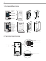
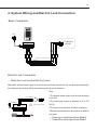
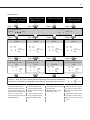
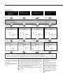
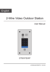
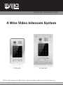
VT596(F)/KP USER MANUAL(EN) 4 Wire Video Intercom System VT596/KP VT596F/KP Read this manual carefully before using the product, and keep it well for future use. -1- 1. Parts and Functions Camera Lens 1 2 3 4 5 6 7 8 9 * 0 # Indicator(red) Indicator(blue) Touch Sensitive Digital Keypad 176 mm Speaker Nameplate Call Button Microphone 1 2 3 4 5 6 7 8 9 * 0 # 28 mm Rainy Cover VT596/KP 90 mm Camera Lens 1 2 3 4 5 6 7 8 9 * 0 # Indicator(red) Indicator(blue) Touch Sensitive Digital Keypad Nameplate Call Button Screws for panel mounting Microphone 220 mm Speaker 1 2 3 4 5 6 7 8 9 * 0 # VT596F/KP Side View 119 mm Mounting box ON 1 2 3 DIP 1 2 3 4 2. Terminal Descriptions MIC adjustment SPK adjustment JP/LK Lock Control Jumper RS485 Connect Port S- S+ PL 1R 2W 3Y 4B DC+ DC- DIP Switches Main Connect Port -2•• •• •• •• •• •• •• •• •• •• •• •• •• •• JP/LK(Lock Control Jumper): To select the lock type: see section 4(lock connect) DIP Switches: Reserve. RS485:Used to update the program MIC: Adjust the volume of Microphone SPK: Adjust the volume of Speaker Main Connect Port: To connect the bus line and the electronic locks. DC+,DC-: Power supply connection port,16~24V, polarity. 1R: Power positive. +12V present when outdoor station calling or being monitored. 2W: Power negative (GND) 3Y: Image signal (Video signal) 4B: Talk and control signal (Audio signal) PL: External lock power input, connect to the power positive(power +). S+: Lock power(+) output. S-: Lock power(-) output. 3. Door Station Mounting VT596/KP Mounting 1 2 adjust camera angle 4 core cable PS Drill holes in the wall to match the size of screws and attach the rainy cover to the wall. 3 Connect the cable correctly and adjust right angle for camera 4 Attach the panel to the rainy cover Use the screwdriver and the screw to fix the panel -3- VT596F/KP Mounting 1 2 adjust camera angle m 174mm 90m 52m m 4 core cable PS Drill a hole in the wall to match the size of the mounting box and attach to the wall. 3 Connect the cable correctly and adjust right angle for camera 4 Attach the panel to the mounting box and use screws supplied to fix the panel Place name label Placing Name Label 1 2 3 4 5 6 7 8 9 * 0 # Press the plastic cover on right/left side to move away the cover, insert a name paper, then put the plastic cover back to the panel. -4- 4. System Wiring and Electric Lock Connection 0 # * TO Monitor JS/OS1 Red 1R 2W 3Y 4B 1R 2W 3Y 4B Yellow 9 Black 6 8 White 3 5 S- 2 4 S+ 1 7 1R 2W 3Y 4B DC- DC+ AC ~ PL Basic Connection Shielding Layer of the RVVP Cable Electric Lock Connection •• Mode1:Door Lock Controlled With Dry Contact Must install external power supply for lock,and nearly all kinds of electronic lock can be used.Incidentally,in this mode,you can continue talking and monitoring during unlock operation. Note: S- S+ PL Take off JP/LK Jumper 1R 2W 3Y 4B DC+ VT596(F) DC- 1.The external power supply must be used according to the lock. 2.The inside relay contact is restricted to AC or DC 24V/1A. 3.The jumper must be taken off before connecting. 4.Setup the Unlock Mode on door station for different lock types. White Black Red AC ~ 1R 2W 3Y 4B Connect to Monitor POWER + SUPPLY - + - LOCK •• Power-on-to-unlock type:Unlock Mode=0 •• Power-off-to-unlock type:Unlock Mode=1 -5•• Mode2:Door Lock Controlled With Internal Power The lock can be directly connected with the door station and the power through monitor.During unlock operation,the monitor will close screen automatically. Note: 1 2 3 S- S+ PL 1.Electronic lock of power-on-to-unlock shoule be used. 2.The door lock is limited to 12V,and holding current must be less than 250mA 3.The door lock control is not timed from Exit Button(EB). Red Black White 1R 2W 3Y 4B DC+ JP/LK Jumper position in 2-3 Unlock mode:0 VT596(F) DC- AC ~ 1R 2W 3Y 4B Connect to Monitor + LOCK 4. The Unlock Mode Parameter of Monitor must be set to 0 (by default). 5. Functions Setting Up This section explains the settings of each function,please refer to the following table: About the setting mode: Input the master code to switch to the setting mode, and input the corresponding setting code to perform the settings for the function you want. After settings have been made, input the following setting codes to continue the setting operation. Press " " to exit the setting mode. •• The example is set as cancel button and # as confirm button,please refer to */# function setting for detail information. •• Forbid to slide to touch the digital keypad,it may cause mistaken key,the correct operation is using your finger to press the digital you desired. •• You should press“confirm”button after finish inputting the code number each time,otherwise,the operation will be canceled automatically in 10s. -6- Order Setting items Setting range Default value Setting code 1 Reset all settings 1234 - 00 2 Setting the master code 1234 01 3 Setting the key illumination time 1 ~ 12 digits Valid keys:0 ~ 9 10 to 99 seconds/ continually lit(00s) 10 seconds 02 4 Setting the unlock time 01 to 99 seconds 1 seconds 03 5 Setting the unlock mode 0:opened/1:closed opened 04 6 Operation tone settings 0:on/1:off on 05 7 Reset code settings 1234 - 06 8 &# function settings 0:Normal/1:Reverse Normal 07 9 Reserve Reserve Reserve 08 10 Interference resistant grade settings Valid keys:0 ~ 5 2 09 11 Reserve Reserve Reserve 10~17 Setting the code forTemporary1 Setting the code forTemporary2 1 ~ 12 digits Valid keys:0~9 1 ~ 12 digits Valid keys:0~9 1 ~ 12 digits Number of codes:80 Valid keys:0~9 - 18 - 19 - 20~99 12 13 Setting the code for user 14 About Functions Setting steps 1 2 3 4 5 6 7 8 9 * 0 # red blue Each operation is indicated by the lighting up of the LED indicators on the right section of the unit, and by the sounding of the buzzer. -7- Setting items 1.Reset all settings 2.Setting the master code (Default Step 1 1234) Step 1 3.Setting the key illumination time (Default 10s) Step 1 Step 1 (red) ON Input the master code. (Default: [ 4.Setting the unlock time (Default 1s) (blue) OFF ] +[#] ) Step 2 Beep+, Beep Step 2 Step 2 Step 2 Input the setting code. Input the setting code. Input the setting code. Input the setting code. 00+# 01+# 02+# 03+# (red) ON (blue) ON (red) ON (blue) ON Beep+, Beep Step 3 - When the “ Beep+ Beep+, Beep Step 3 Inputting of code (ex.: 10) range:00 or 10~99 Inputting of code (ex.: 09) range:01~99 10+# (red) ON (blue) OFF (blue) OFF (blue) OFF Beep+ - When there isn’t any operation in 10s, the LED lights off, the buzzer beeps, and the system exits the setting mode - The master code is allowed 1~12 digits,the same code cannot be set for both the user code and the master code,it is recommended that you modify the default master code. 09+# (red) ON * cancel” key is pressed, the LED lights off, the buzzer beeps, and the system exits the setting mode - All settings will restore to their default value. - When power on or activate the reset all setting item,the keypad checking will carry out, during this time,the key illumination will blink and the touching operation is forbidden, after finish checking,the key illumination will stop blinking and sent out a long sound of beep (blue) ON Beep+, Beep 4321+# (red) ON Beep+ (red) ON Step 3 Inputting of new master code (ex.: 4321)(1~12 digits) 1234+# (blue) OFF (blue) ON Beep+, Beep Step 3 Inputting of code (red) ON (red) ON Beep+ (red) OFF (blue) OFF Beep, Beep+ - The unlock time is the time that - If the key illumination time is set use keypad access to unlock. to 00,the key illumination will light up all the time when power on. - If the key illumination time is set to 10~99,the key illumination will light up for 10~99 seconds.At this mode, the key illumination lights off in standby mode, touching any digital key can illuminate,but this is the invalid digital. -8- Setting items 5.Setting the unlock mode (Default 0(opened)) Step 1 6.Setting operation tone (Default ON) Step 1 Step 1 Step 1 (red) ON Input the master code. (Default: [ * 8. &# function setting (Default Normal) 7.Reset code setting (blue) OFF ] +[#]) Step 2 Beep+, Beep Step 2 Step 2 Step 2 Input the setting code. Input the setting code. Input the setting code. Input the setting code. 04+# 05+# 06+# 07+# (red) ON (blue) ON (red) ON (blue) ON Beep+, Beep Step 3 0/1 Inputting of code (ex.: range:0:(open)/1:(close) 1) 1+# (red) ON (blue) OFF - When the “ (blue) ON Beep+, Beep 0/1 Step 3 Inputting of code (ex.: range:0:(on)/1:(off) 1) (blue) OFF Step 3 Inputting of code 1234+# (red) ON Beep+ (red) ON 0/1 Step 3 Inputting of code (ex.: 1) range:0:(normal)/1:(reverse) 1+# (blue) OFF Beep+ Beep+ - When there isn’t any operation in 10s, the LED lights off, the buzzer beeps, and the system exits the setting mode - When the operation tone is set to 0,pressing the digital keypad will sent out a sound of beep. - When the operation tone is set to 1,pressing the digital keypad will blink one time. Beep+, Beep (red) ON (blue) OFF * cancel” key is pressed, the LED lights off, the buzzer beeps, and the system exits the setting mode - The unlock mode is used to match the type of lock,If it’s set to 0,unlock mode is power-on-to unlock,and must use electric lock. If it’s set to 1,unlock mode is power-off-to-unlock,and must use electromagnetic lock. (blue) ON Beep+, Beep 1+# (red) ON Beep+ (red) ON - Cancel all the passwords except the master code. - Restore the master code to default value(1,2,3,4) (red) OFF (blue) OFF Beep, Beep+ - When the item is set to 0,press the button to cancel the input, * and press the # button to confirm the input. - When the item is set to 1,press the # button to cancel the input, and press the * button to confirm the input . -9- Setting items 10.Interference resistant grade setting (Default 2) 12.Setting the code forTemporary1 Step 1 Step 1 13.Setting the code forTemporary2 Step 1 Step 1 (red) ON Input the master code. (Default: [ 14.Setting the code for user (blue) OFF ]+[#] ) Beep+, Beep Step 2 Step 2 Step 2 Step 2 Input the setting code. Input the setting code. Input the setting code. 09+# 18+# 19+# (red) ON (blue) ON (blue) ON Inputting of code (ex.: 3) range:0~5 3+# - When the “ Beep+, Beep Step 3 Step 3 Inputting of code (ex.: 1006) 1~12 digits Inputting of code (ex.: 2011) 1~12 digits Inputting of code (ex.: 2011) 1~12 digits (blue) OFF Beep+ 2011+# 2011+# (red) ON (blue) OFF (red) ON (blue) OFF Beep+ Beep+ * cancel” key is pressed, the LED lights off, the buzzer beeps, and the system exits the setting mode - When there isn’t any operation in 10s, the LED lights off, the buzzer beeps, and the system exits the setting mode - The larger you set the interference resistant grade,the stronger it will be, but the sensitivity of the keypad will be more lower. - The interference resistant grade setting also will activatethe keypad checking. (blue) ON Beep+, Beep 1006+# Beep+ (red) ON Step 3 (red) ON (blue) OFF 21+# (blue) ON Beep+, Beep Beep+, Beep Step 3 (red) ON 20~99 Input the setting code. (ex.:21) - When input the correct temporary password to release the door, the system will clear the temporary password after 60 seconds automatically.But you should know that the password is valid within 60 seconds after inputing the correct temporary password - If the password length exceeds 12 digits, the system will sent out the sound of “beep,beep,beep,beep”,and the digitals you input before will be cleared at the same time. - The temporary code can not be set the same as the master code and user code. (red) OFF (blue) OFF Beep, Beep+ - The user code is used to release the lock,80 group passwords can be supported. - If the password length exceeds 12 digits, the system will sent out the sound of “beep,beep,beep,beep”, and the digitals you input before will be cleared at the same time. - The user code can not be set the same as the master code and temporary code. -10- 6. Unlock Operations Unlocking of user code When the registered user code has been input using the keypad (1~12 digits), the LED indicator (red) lights up, the buzzer sounds,and the electric door strike is unlocked.(note that you should press "#" button(if "#" button is set to confirm button) after input the unlock code) Example: Unlock code=2011 Red LED lights up (during relay1 operation) (red) ON (blue) OFF Beep+ •• The time interval during which the button must be pressed is approximately 10 seconds. If the time interval exceeds approximately 10 seconds, the input value will be cleared. •• If you make a mistake when inputting the user code,press the" cancel" button and input the user code again. •• If 10 times incorrect access codes are continuously attempted, the release function is forbidden and the input operation is disabled for 60 seconds . During this time,the buzzer will continuously sound about 8 times. •• You can activate the electric door strike by pressing the request to exit button connected to the unit. (The unlock function will work when the request to exit button is pushed, even while the keypad operating is forbidden.) 1. During calling,pressing "cancel" button can cancel the calling 2. If input the incorrect access code,the buzzer will sound of beep,beep,beep -11- 7. Precaustions •• Please clean the unit with soft cotton cloth, don't use the organic impregnant or chemical clean agent. If necessary, please use a little pure water or dilute soap water to clean the dust. •• The unit is weather resistant. However do not spray high pressure water on access control keypad directly. Excessive moisture may cause problems with the unit. •• You must use the right adaptor which is supplied by the manufacture or approved by the manufacture.. •• Pay attention to the high voltage inside the products, please refer service only to a trained and qualified professional. 8. Specifications •• •• •• •• •• •• Power Supply : DC 16~20V Power Consumption: Standby 0.5W; Working status 3W; Camera: Pinhole Sharp Color CCD; Unlocking time: 1~99s Lock Power supply: 12Vdc, 300mA(Internal Power); Mounting: Surface mounting(DT596/KP) Flush mounting (DT596F/KP) •• Working temperature: -10ºC ~ +45ºC •• Dimension: 176(H)×90(W)×28(D)mm(DT596/KP) 220(H)×119(W)×52(D)mm(DT596F/KP) The design and specifications can be modified without notice to the user. Right to interpret and copyright of this manual are preserved. Printed In China / 2011. 09