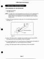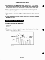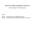
1
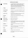
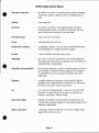
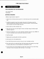
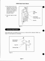
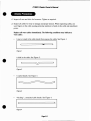
Classic Owners Manual
Strength Systems
Part No. 491 0 0698
Disclaimer:
Cybex International, Inc., makes no representations or warranties regarding the contents of this manual. We reserve the right to revise this
document at any time or to make changes to the product described within it without notice or obligation to notify any person of such revisions or
changes.
©Copyright 1993, 1994, 1995, 1996, 1997, 1998 Cybex International, Inc. All rights reserved.
Printed in the United States of America.
•
•
•
TABLE OF CONTENTS
1 GENERAL EXERCISE GUIDELINES
General Exercise Guidelines
Glossary
Exercise Charts
Single Set Exercise Chart.
Multiple Set Exercise Chart
1-1
1-2
No Page Number
No Page Number
2 EXERCISES
Pullover
4000
Lat Pulldown
4005
Rowing
4010
Chest Press
4015
Fly
4022
Shoulder Press
4025
Lateral Raise
4031
Tricep Extension
4035
Arm Curl
4040
Tricep Press
4055
Incline Press
4060
Leg Extension
4105, 4108 with RLD
Leg Curl. . . . . . . . . . . . . . . . . . . . . . . . . . . . . . . . . . . . . . . . . .. 4110, 4113 with RLD
Standing Calf Raise
'
4117
Multi Hip
4121
Seated Leg Curl
41 32
Hip Adduction
4140
Hip Abduction
4145
Rotary Torso
4201
.4205,4208 with RLD
Back Extension
Abdominal
421 2
3 CUSTOMER SERVICE
Ordering Parts
CYBEX Limited Warranty
3-1
3-1
4 DELIVERY & INSTALLATION
Delivery Inspection
Installation
Anchoring
Safety
Weight Stack Installation
Servicing Weight Stacks
4-1
4-1
4-2
4-2
4-3
4-4
5 MAINTENANCE
5-1
5-1
Caution Statement
Daily Procedures
Weekly Procedures
Yearly Procedures
"As Requirecf' Procedures
Cable Adjustment
Cable Tension Check
Alternative Cable Tension Check
Cable Tension - Jam Nut Adjustment
Cable Tension - Rod End Adjustment.
Cable Tension - Roll Pin Adjustment
Cable Tension - Nylon Insert Nut Adjustment.
5-3
5-5
5-5
5-5
5-7
5-7
5-8
5-9
5-1 0
5-11
6 SERVICE
General
Caution Statement
Grip Replacement
Pullover
Lat Pulldown
Rowing
Chest Press
Fly
Shoulder Press
Lateral Raise
Tricep Extension
Arm Curl
Tricep Press
Incline Press
Leg Extension
Leg Curl
Standing Calf Raise
Multi Hip
Seated Leg Curl
Hip Adduction
Hip Abduction
Rotary Torso
Back Extension
Abdominal
,
6-1
6-1
6-1
4000
4005
4010
4015
4022
4025
4031
4035
4040
4055
4060
4105, 4108 with RLD
4110,4113 with RLD
411 7
4121
41 32
4140
41 45
4201
.4205,4208 with RLD
4212
•
CHAPTER 1 - GENERAL EXERCISE GUIDELINES
•
General
Like any sport, strength training involves an element of risk. The following recommendations
will help to ensure that training is as productive and safe as possible.
Prior to embarking on any strength training program, it is recommended that each user consult
with a physician.
All training sessions should be supervised by trained personnel.
Be sure all warning labels are read and understood by each user.
It is very important that all users be instructed on 'the proper use of CYBEX Strength Systems
products. Pay close attention to the following:
• Set up and alignment for each individual entry and exit from the unit
• Proper fonn
• Use of seat belts, safety catches and other safety features
To minimize the chance of injury:
•
•
•
•
•
Do not lean on the weight stack or other moving parts
Keep clear of safety catches, belts and pulleys
Have a spotter present
Do not exceed any exercise or movement restrictions prescribed by a doctor, therapist
or trainer. This is particularly important for those at risk due to:
-- Known heart disease
-- Known hypertension
-- Obesity
Instruct all users to report any equipment irregularity or personal injury to supervisory personnel immediately.
Page 1-1
CYBEX Classic Owners Manual
Glossary
Acceleration
the rate at which an object's velocity changes with time; that
is the change of velocity divided by the time interval.
Accuracy
freedom from error. Degree of conformity of a measure to a
standard or a true value.
Adipose tissue
fat tissue.
Aerobic
utilizing oxygen.
Aerobic endurance
the ability to persist in physical activities that rely heavily
upon oxygen for energy production.
Anabolic
pertaining to the synthesis of complex substances from
simpler substances, especially to the synthesis of body
proteins from amino acids.
Anaerobic
without oxygen.
Anaerobic endurance
the ability to persist in physical activities of short duration
that require high rates of energy expenditure. These high rates
of energy expenditure cannot be met solely by aerobic
metabolism.
Anthropometries
measurements and relationships of length and girth of body
parts.
Atrophy
reduction in size of cells and tissues.
Body composition
the component parts of the body - mainly fat and fat-free
weight.
Calorie
a unit of work or energy equal to the amount of heat required
to raise the temperature of 1 g of water to I degree C.
Cam
a mechanical device used to vary leverage.
Carbohydrate
a chemical compound consisting of carbon, hydrogen and
oxygen atoms in specified arrangements. Carbohydrates are
major components of food such as bread, potatoes and rice.
Cardiovascular
pertaining to the heart and blood vessels.
Pags1-2
•
•
CYBEX Classic Owner's Manual
•
•
Circuit Training
a conditioning program consisting of a number of exercises
perfonned at "stations". Usually, a given exercise is perfonned at a station within a specified time; then the athlete
moves to the next station, with its own particular exercise and
pecified time, then to the next station, and so on.
Collagen
a fibrou protein that serves as the major component of ligaments and tendons.
Concentric action
contraction of a muscle resulting in shortening of the muscle.
Cross bridges
the linkages between actin and myosin filaments during muscle contraction.
Eccentric action
a muscle contraction incapable of overcoming the resistance
impo ed; the overall muscle length increases.
Endurance
the ability to persist in perfonning some physical activity.
Energy
the capacity to perfonn work.
Energy (kinetic)
energy associated with motion.
Energy (potential)
energy by virtue of position.
Energy system
one of three metabolic systems involving a series of chemical
reactions resulting in the fonnation of waste products and the
manufacture of ATP.
Ergometer
a device which can measure work done, e.g., a bicycle
ergometer.
Fast twitch fibers
keletal mu c1e fibers most active in short-duration, inten ive
exerci e, e.g., in sprints and jump .
Fatigue
the inability to maintain a given level of physical performance.
Flexibility
the range of motion of the body s joints.
Foot-pound
the work required to move one pound of resistance one
foot in distance.
•
Page 1-3
CYBEX Classic Owners Manual
Force
a push or pull exerted upon some object; an action exerted by
one body on another that tends to change the state of motion
of the body acted upon.
Hypertrophy
increased cell size leading to increased tissue size.
Inertia
the property of an object that allows it to stay in rest or
motion. An object with high inertia is difficult to set in
motion. Once in motion, it is difficult to top.
Intermittent work
work sessions intenupted by rest sessions.
Isokinetic contraction
a muscular contraction through a range of motion at a constant velocity.
Isometric (static)
contraction
a muscular contraction in which there is no change in the
angle of the involved joint(s) and little or no change in the
length of the contracting muscle.
Isotonic contraction
a muscular contraction in which a constant resistance is
moved through a range of motion of the involved joint(s).
Kilocalorie
a unit of work or energy equal to the amount of heat required
to raise the temperature of I kg of water I degree C.
Kinetic energy
energy associated with motion.
Lactic acid (lactate)
the end-product of anaerobic glycolysis.
Lean body mass
the body mass that does not include fat tissue.
Ligament
the tough connective tissue that binds bone together at joints.
Mass
the amount of matter an object contains, or the number of
atoms. Unlike weight, an objects mass is constant, despite the
value of gravitational acceleration. Mas i a determiner of an
object s inertia.
Metabolism
the sum total of the chemical changes or reactions occurring in the body.
•
•
Page 1-4
CYBEX Classic Owner's Manual
•
•
Muscular endurance
the ability of a muscle or muscle group to perform repeated
contraction against a light load for an extended period of
time.
Obesity
excess body fat.
Overload
to exerci e a muscle or muscle group against resistance
greater than that which is normally encountered. The resistance (load) can be maximal or near-maximal.
Potential energy
energy by virtue of position.
Power
work performed per unit time.
Progressive resistance
overloading a muscle or muscle group consistently throughout the duration of a weight-resistance program.
Protein
a basic foodstuff containing amino acids.
Reliability
the extent to which an experiment te t or mea uring procedure yields the ame results on repeated trials. Also known as
reproducibility or repeatability.
Repetition maximum(RM) -
the maximum load that a muscle or mu cle group can lift in a
given number of repetitions before fatiguing. For example,
an eight-RM load i the maximum load that can be lifted
eight times.
Response
a sudden temporary adjustment in phy iological function
brought on by a single exposure to exercise, e.g., the rise in
heart rate associated with an exercise bout.
Set
in an interval training program, a group of work and relief
interval . In weight lifting, the number of repetitions performed consecutively without re ting.
Slow-twitch fibers
skeletal muscle fiber characterized by relatively slow contraction time and great capacity for the aerobic production of
adenosine triphosphate.
Static contraction
a muscular contraction that does not involve changes in the
angle of the joint(s) involved.
•
Page
1~
CYSEX Classic Owner's Manual
Steady state
that state of physiological stability wherein the energy
demands of the body can be met relatively easily for a prolonged period of time.
Strength
the ability to exert muscular force briefly.
Submaximal exercise
usually exercise at less than maximal intensity, but may also
refer to exercise of less than maximal duration.
Torque
the force exerted in rotating an object about an axis of rotation; it is the production of perpendicular force (F) and the
length of the lever arm (d): T=Fd.
Training
a program of exercise designed to improve the skills and
increase the energy capacities of an athlete for a particular
event.
Validity
the extent to which a measurement or infonnation is relevant
or meaningful; appropriate to the end in view and supported
by objective truth.
Velocity
the rate at which an objects position changes with time; that
is the total change in position divided by the total change in
time: V-dlt.
Weight
the weight of an object is the gravitational force exerted on it
by the earth. W=mg, where g = gravitational acceleration.
Work
W = Fd. The amount of work perfonned is equivalent to the
force applied to an object times the distance the object is
moved.
•
•
Page
1~
• <>l:VBEX'
•
NAME
INSTRUCTOR,
•
_
Single-Set & Circuit Training Diary
MACHINE
~ / / / / 1/1/ / / / 1/ / / 1/1/ / / / V1/ / / /V1/VV1/1/1/1/1/1/1/ / / / / '/ / 1/
Date
/
/
/
/
/
/
/
/
/
/
/
/
Plates
Reps
Plates
Reps
Plates
Reps
Plates
Reps
Plates
Reps
Plates
Reps
Plates
Reps
Plates
Reps
Plates
Reps
Plates
Reps
Plates
Reps
Plates
Reps
<">I:VBEX·
MACHINE
Single-Set & Circuit Training Diary
~ 1/1/1/ / 1/1/1/1/ / 1/1/1/ / 1/1/ / 1/1/1/ / 1/1/1/ /VVVV1/1/1/1/1/1/VVVV1/1/
Date
/
V
V
1/
1/
/
/
V
V
V
V
V
Plates
Reps
Plates
Reps
Plates
Reps
Plates
Reps
Plates
Reps
Plates
Reps
Plates
Reps
Plates
Reps
Plates
Reps
Plates
Reps
Plates
Reps
Plates
Reps
•
~~l:VBEX·
•
NAME
INSTRUCTOR
,
_
Multiple-Set Training Diary
MACHINE
fj
Date
/
Plates
/
/
/
/
/
/
/
,
/
/
/
V
Set
Reps
Plates
Reps
Plates
Reps
Plates
Reps
Plates
Reps
Plates
Reps
Plates
Reps
Plates
RePs
Plates
Reps
Plates
Reps
Plates
Reps
Plates
Reps
1 2 3 1 2 3 1 2 3 1 2 3 1 2 3 1 2 3 1 2 3 1 2 3 1 2 3 1 2 3 1 2 3 1 2 3 1 2 3
~~l:VBEX·
MACHINE
!~
/
/
/
/
/
/
~
~
,.
~
'/
/
/
/
V
/
Multiple-Set Training Diary
Date
Set 1 2 3 1 2 3 1 2 3 1 2 3 1 2 3 1 2 3 1 2 3 1 2 3 1 2 3 1 2 3 1 2 3 1 2 3 1 2 3
Plates
Reps
Plates
Reps
Plates
Reps
Plates
Reps
Plates
Reps
Plates
Reps
Plates
Reps
Plates
Reps
Plates
Reps
Plates
Reps
Plates
Reps
Plates
Reps
•
2
SAFETY
Strength training can be a safe and rewarding
activity. Always follow the recommendations
listed below as they can help ensure training is
productive and free from injury.
1. All Training or rehabilitation sessions should
be supervised by trained personnel.
4. Instruct all users to report any equipment
irregularity or personal injury to supervisory
personnel immediately.
5. Instruct all personal in equipment inspection
and accident recording/reporting.
6. Inspect and maintain equipment at regular
intervals. Pay particular attention to cable
and hardware inspection as noted in
Section 3.
2. It is very important that all users be
instructed on the proper use of each
CYBEX Modular Strength systems.
Particular attention should be given to the
following:
7. Use extra caution when assembling and
installing equipment, particularly when lifting
or moving heavy objects (Le. installing
weight stacks) and when using power tools.
A. Setup and alignment for each individual.
B. Entrance and exit from the unit.
8. CAUTION: CYBEX recommends anchoring
all CYBEX Strength Systems equipment to
the floor for maximum safety.
C. Proper form when using the unit.
•
3. To reduce chance of injury, users should
adhere to the following rules:
NOTE: CYBEX is not responsible for the
actual anchoring of equipment. Consult with
a professional contractor.
A. Keep head and limbs clear of
cable/pulley junction(s).
B. Do not exceed any exercise or
Use fasteners having a minimum of 500 Ibs
tensile capacity (3/8" grade 2 bolt or
better).
movement restrictions prescribed by a
doctor or therapist. This is particularly
important for those at risk due to:
• Known heart disease
• Known hypertension (high blood pressure)
• Obesity
•
2-1
If aI/legs/frames do not contact surface,
DO NOT pull down with anchors. Shim any
leg or frame not in contact with surface with
flat washers.
4000
•
MUSCLES TRAINED
Latissimus Dorsi, Pectoralis, Teres Major/Minor, Abdominals.
Anterior/Posterior Deltoids
Latissimus Dorsi
•
Abdominals
The CYBEX Pullover incorporates an adjustable pin
system to tailor the range of motion to suit individual
users as well as an adjustable seat for precise axis
alignment. Entry and exit is made simple through the
use of a foot lever advance which is used to bring the
pullover arm into the start position after the user is
seated. An upholstered seat belt is standard.
Machine weight: 535 Ibs.
Weight stack:
2501bs.
Dimensions:
38" w x 54"1
Graduated weight stack also available
INSTRUCTIONS
1. Adjust seat height so that shoulder joint is aligned
with the axis of the cam.
2. Press foot lever advance toward floor to move the
Pullover arm to the start position; locate elbows on
the pads provided.
3. Set range limiting (if desired) by inserting range of
motion pin in position located on righthand side of
machine next to cam.
4. Keep a light grip on the bar while pushing down
with elbows.
•
SPECIFICATIONS:
5. Start and end movement with smooth, controlled
movements.
6. When finished, depress foot lever advance to return weights and exit the machine.
4005
Latissimus Dorsi, Teres Major, Pectoralis group, Rhomboids,
Brachialis, Biceps
Rhomboids
Biceps
SPECIFICATIONS:
•
The CYBEX Lat PuBdown features adjustable knee
pads for stabilization when training with resistance
greater than bodyweight. Wide and narrow grip bars
are standard.
INSTRUCTIONS
1. Adjust the thigh pads to allow access and stabiliza-
tion while lifting.
2. Check the weight stack to insure appropriate resistance.
3. Grasp the bar at shoulder width and sit down with
knees under thigh pads.
4. Lean back slightly at hips and maintain.
5. Pinch shoulder blades down and back.
6. Maintaining shoulder position, bend arm and bring
bar down in front of face with elbows alongside
body.
•
7. Smoothly return bar to overhead position while
maintaining hip position.
8. If the shoulder blade position changes during
return motion, reset before beginning each repetition.
Machine weight: 450 lbs.
Weight Stack:
250 lbs.
Dimensions:
32" w x 55" I
4010
•
•
MUSCLES TRAINED
Latissimus Dorsi, Deltoids, Teres MajorlMinor, Infraspinatus,
Rhomboids, Trapezius, Biceps
The CYBEX Rowing machine includes a contoured
sternum pad to reduce lower back involvement and to
promote upper back muscle isolation without interfering with natural arm motion. This pad adjusts to provide
maximum support and proper positioning for any arm
length. The overhead pivot guides the user through a
natural arc of motion and allows the wrists to remain in
a neutral position throughout the complete range of motion.
INSTRUCTIONS
1. Adjust seat height so that arms are approximately
parallel with the floor when grasping the handles.
Some individuals prefer a seat height one setting
higher when using neutral grips.
NOTE: Use of barbell grips emphasizes rear deltoid,
trapezius and rhomboid training; neutral grips emphasize latissimus dorsi recruitment.
2. Adjust sternum pad so that the arms can fully
straighten when the handles are in the start position.
3. Maintain contact with seat and sternum pad at all
times.
•
4. Select neutral or barbell grip.
S. Pull handles toward body with a smooth, controlled motion.
6. Slowly return handles to start position.
SPECIFICATIONS:
Machine Weight: 435 lbs.
Weight Stack:
250 lbs.
Dimensions:
34"w x 60"1
Graduated weight stack also available.
4015
•
MUSCLES TRAINED
Pectoralis group, Anterior Deltoids, Coracobrachialis,serratus Anterior,Triceps
Triceps
Pectoralis Group
The CYBEX Chest Press offers a choice of neutral or
barbell grips, properly angled to prevent inappropriate
joint stress and enhance comfort and lifting ability, The
foot lever advance allows the user to control start position and facilitates easy entry and exit.
•
Machine weight: 510 Ibs.
Weight stack:
2501bs.
Dimensions:
45"w x 55"1
Graduated weight stack also available.
INSTRUCTIONS
1. Adjust seat height so that handles are approximately even with the sternum,
2. Push foot lever advance toward the floor to advance handles to a comfortable start position.
3. Select neutral or barbell grip.
4. Slowly release foot lever advance and place feet
on foot platform or floor.
5. Start movement by pressing the handles forward
with a smooth, continuous motion. DO OT
LOCK OUT ELBOWS at finish position.
6. Slowly return to the start position.
•
SPECIFICATIO S:
7. When finished, depress the foot lever advance, relea e the handles, and gently lower the weight by
returning the foot lever advance to its start positions
4022
•
MUSCLES TRAINED
Pectoralis group
Pectoralis Group
•
The CYBEX Fly incorporates underseat cams for easy
entry and exit and an axis of rotation parallel to the seat
back so that axis alignment remains correct at any seat
height. Dual hand grips accommodate any forearm
length and allow for a properly extended arm position;
optional extended pads are also available (Product #
4022K 140). A foot lever advance allows the user to determine the desired start position and range of motion
while helping to prevent inappropriate joint stress.
INSTRUCTIONS
1. Adjust seat height so that elbows are slightly below shoulders when grasping handles.
2. Press foot lever advance to bring arms to a comfortable start position.
3. Locate forearms on pads and lightly grip handles;
release foot lever advance.
4. Lead with elbows so that they meet in front of
chest.
5. Slowly return to start position with a smooth, continuous motion.
•
6. When finished, press the foot lever advance, release
the handles and gently return weights to the start
position.
SPECIFICATIONS:
Machine weight: 510 Ibs.
Weight stack:
1701bs.
Dimensions:
53"w x 49"1
A graduated weight stack is standard; a nongraduated stack is also available
4025
•
MUSCLES TRAINED
Deltoids, Supraspinatus, Serratus Anterior, Upper
Trapezius, Subscapularis. Triceps
Triceps
The CYBEX Shoulder Press has dual hand grips and a
counterbalanced input arm to allow even inexperienced
or deconditioned exerciser to develop overhead lifting
strength. An adju table seat height ensures optimal positioning and range of motion control.
•
SPECIFICATIO S:
Machine weight: 440 Ibs.
Weight stack:
187.5Ibs.
46"w x 64"1
Dimensions:
Graduated weight stack also available.
INSTRUCTIONS
I. Adjust eat height so that handles are level with
tops of houlders.
OTE: To reduce range of motion, lower seat height
one position.
2. Select neutral or barbell grips.
NOTE: Neutral grip position increases anterior deltoid recruitment.
3. Start movement by pre sing upward with a
smooth, continuous motion.
4. Slowly return weights to start positions.
4031
•
MUSCLES TRAINED
Trapezius, Deltoid
Deltoids
•
The CYBEX Lateral Raise is designed with a slight forward angle to enhance stability and isolation by utilizing
the effect of the user's bodyweight. The exercise anns
are counterbalanced to reduce the starting resistance and
the grips swivel automatically to accommodate foreann
lengths for maximum comfort
Machine weight: 380 lbs.
Weight stack:
187.5 Ibs.
Dimensions:
27"w x 46"1
Graduated weight stack also available.
INSTRUCTIONS
1. Adjust seat height so that the shoulders align with
the axis of the cams.
NOTE: Pads should remain in consistent contact with
arm during use; ifpad slides up, adjust seat height one
position higher./fpad slides down, adjust seat height
one position lower.
2. Maintain contact with the chest pad.
3. Grip handles lightly and push elbows out with a
smooth, continuous motion until elbows are at
shoulder height.
4. Slowly return to the start position.
•
SPECIFICATIONS:
4035
•
MUSCLES TRAINED
Triceps, Flexor/Extensor Carpi Ulnaris
Triceps
The CYBEX Tricep Extension features an adjustable
seat and backpad to accommodate vinually any torso
length and to provide correct axis alignment. The handle
design automatically adjusts for any forearm length to
provide optimum triceps isolation.
•
Machine weight: 395 lbs.
Weight stack:
187.5Ibs.
Dimensions:
35"w x 42"1
Graduated weight stack also available.
INSTRUCTIONS
1. Adjust seat height so that upper arm is parallel to
the floor.
2. Adjust backpad so that elbows are positioned on
the center of the pad.
3. Grip handles lightly.
4. Start movement by straightening arms while maintaining contact with the upper arm on the elbow
pad.
5. Slowly return to starting position with a smooth,
controlled motion.
•
SPECIFICATIO S:
4040
Biceps
•
The CYBEX Ann Curl encourages correct alignment,
proper fonn and easy reproduceability from session to
session by providing engraved, numerically indexed adjustments for both the chest pad and seat height. In addition, the handles pivot to automatically accommodate
any foreann length.
Machine weight: 380 lbs.
Weight stack:
187.5 lbs.
Dimensions:
35"w x 40"1
Graduated weight stack also available
INSTRUCTIONS
1. Adjust seat height so that upper ann is parallel to
the floor.
2. Adjust chest pad so that the elbows are positioned
in the center of the pad.
3. Grip handles lightly with palms up.
4. Stan movement by bending elbows, bringing
hands toward forehead.
5. Slowly return the weight to the start position with
a smooth, controlled movement.
•
SPECIFICATIO S:
4055
MUSCLES TRAINED
•
Triceps, Pectoralis group, Latissimus Dorsi, Deltoids
The CYBEX Tricep Press allows users to simulate
bodyweight dips with resistance in small increments.
Handgrips adjust in width for any size user, and a seatbelt is included for training with heavier-thanbodyweight resistance.
•
Machine weight: 540 lbs.
Weight stack:
2501bs.
Dimensions:
38"w x 53"1
Graduated weight stack also available.
INSTRUCTIONS
1. Adjust seat height to yield desired range of motion.
2. Select wide or narrow grip position by rotating
handles in or out. Select the narrowest position
which clears hips.
3. Fasten seat belt if desired.
4. Start movement by pressing handles downward
with a smooth, controlled motion.
5. Slowly retum weight to starting position.
•
SPECIFICATIONS:
4060
MUSCLES TRAINED
•
Pectoralis group, Deltoids, serratus Anterior, Triceps
Triceps
•
Pectoralis Group
The CYBEX Incline Press utilizes an unconventional angle to reduce the machine footprint and to offer easy ingress and egress as well as a comfortable upright orientation. Both neutral and barbell grips are provided for comfon and training variability. A convenient foot lever advance and non-skid foot platform are also included for
user safety and convenience.
SPECIFICATIONS:
Machine weight: 535 lbs.
Weight stack:
2501bs.
Dimensions:
47"w x 64"1
Graduated weight stack also available.
INSTRUCTIONS
1. Adjust seat height so that barbell grips are even
with chest.
NOTE: Raising the seat height above this level will
emphasize the training effect on the pectoralis group,
while decreasing the emphasis on the anterior deltoid
muscles. Lowering the seat height below this level will
increase emphasis on the anterior deltoiUs.
2. Press the foot lever advance to move handles forward.
3. Select neutral or barbell grips.
4. Slowly release foot lever advance and place feet on
•
foot platform or floor.
s.
Start movement by pressing the handles forward
with a smooth, continuous motion.
6. Slowly return to the start position.
7. When finished, use foot lever advance to return
weights, and exit the machine.
4105 4108 with RLD
•
MUSCLES TRAINED
Quadriceps. Rectus Femoris
Quadriceps
•
The CYBEX Leg Extension is designed to provide
correct, consistent alignment with the knee axis of rotation for maximum safety and effectiveness. The unit
also features an offset input arm which allows the pad
to adjust for tibia length without affecting the start position of the knee. A contoured eat pad facilitates
easy entry and exit and enhances stability without limiting available range of motion.
INSTRUCTIONS
1. Adjust shin pad 0 that pad rests just above the ankle.
2. Adjust backpad so that knees align with machine
axis of rotation; area behind knees should lightly
contact the edge of the seat pad.
3. Start movement by slowly extending legs with a
smooth, controlled motion.
4. Slowly return to start position .
•
SPECIFICATIONS:
Machine weight: 500 Ibs.
250 Ibs.
Weight stack:
36"w x 43"1
Dimensions:
Graduated weight stack also available.
4110 4113 with RLD
•
Hamstrings. Gastrocnemius. Sartorius/Gracilis
Hamstrings
•
The CYBEX Leg Curl incorporates a divergent angle
between hip and chest pads to minimize the possibility
of back hyperextension and to allow the user to lift more
weight than would be possible on a traditional flat
bench. In addition, the chest pad is contoured to encourage the user's hands to fall naturally to the grips for
maximum stability.
INSTRUCTIONS
1. Adjust the leg pad so that pad is positioned just
above the Achilles tendon.
2. Adjust body position on bench so that knees are
located off the bench and are aligned with the
machines axis of rotation.
3. Stan movement by curling heels to buttocks
with a smooth, controlled motion.
4. Slowly return to start position.
•
SPECIFICATIONS:
Machine weight: 485 Lbs.
Weight stack:
250 Lbs.
Dimensions:
36"w x 64"1
Graduated weight stack also available.
4117
•
MUSCLES TRAINED
Gastrocnemius, Soleus, Plantaris
Soleus
•
Plantaris Gastrocnemius
The CYBEX Standing Calf Raise offers dual foot
plates and an adjustable input arm to accommodate
users of any height in the correct exercise position.
This unit also offers a I: I lifting ratio and an optional
free weight kit which allows the addition of Olympic
plates for resistance above the 300 pounds on the
weight stack (Product # 4117K052.)
Machine weight: 365 lbs.
Weight stack:
300 lbs.
Dimensions:
47"w x 30"1
Graduated weight stack also available.
INSTRUCTIONS
1. Select the footplate which allows the shoulder
pads to be as close to parallel with the ground as
possible.
NOTE: Individuals 5'2" or under generally use
upper Joorplare.
2. Adjust the shoulder pads so that the weight plates
selected are in a slightly raised position when
heels are in full dorsi flexion. Maintain correct
posture: Chin in, shoulders back, chest high, knees
over toes, hips tucked in.
3. Start movement by elevating heels as far up as
possible with a smooth, continuous motion.
•
SPECIFICATIONS:
4. Slowly return to the starting position by lowering
heels.
4121
Iliopsoas, Rectus Femoris, Pectineus, Gluteal
group, Hamstrings, Adductor Magnus, Longus,
Brevis, Gracilis, Gluteus Medius, Minimus,
Maximus, Tensor Fasciae, Sartorius
Hip Flexors, Hip Extensors,
Hip Adductors, Hip Abductors.
•
The CYBEX Multi Hip provides a comfortable and functional standing position for hip flexion/extension and abduction/adduction in one space-efficient fonnat. An adjustable foot platfonn facilitates correct axis alignment
regardless of hip height. The stan position is adjustable
in 15° increments to accommodate the different exercises and individual ranges of motion.
INSTRUCTIONS
1. Adjust platfonn height so that hip joint aligns with
the axis of the pivot arm.
2. Adjust position of the leg pad so that the pad contact is just above the knee.
3. Select exercise. The reference chart on the following page indicates the correct procedures for each
movement.
4. Align the involved joint with the axis of the pivot
arm and grasp handles for stabilization.
5. Stan and end movement with smooth, controlled
motions.
•
SPECIFICA TIO S:
Machine weight: 510 Ibs.
Weight stack:
250 Ibs.
Dimensions:
28"w x 58"1
Graduated weight stack also available.
HIP FLEXION
HIP EXTENSION
A. For RIGHT HIP FLEXION: Position the leg pad
between 4 and 6 o'clock.
A. For RIGHT HIP EXTENSION: Position the leg
pad between 7 and 9 o'clock.
For LEFT HIP FLEXION: Position the leg pad
between 6 and 8 o'clock.
For LEFT HIP EXTENSION: Position the leg
pad between 3 and 5 0' clock.
B. Stand as indicated in Fig. I with the side to be exercised closest to the pivot arm. Align the hip with
the axis of the pivot arm and grasp handles for stabilization. The leg pad should be positioned comfortably across the front of the leg, just above the
knee.
B. Stand as indicated in Fig. 2 with the side to be exercised closest to the pivot arm. Align the hip with
the axis of the pivot arm and grasp handles for stabilization. The leg pad should be positioned comfonably across the back of the leg, just above the
knee.
C. Lift the leg bar to complete forward flexion and
lower to extension with smooth, controlled motions.
C. Lift the leg bar to complete backward extension
and lower to flexion with smooth, controlled motions.
Left Hip Extension
Left Hip Flexion
Figure 1
Figure 2
HIP ADDUCTION
HIP ABDUCTION
A. For RIGHT HIP ADDUCTION: Position the leg
pad between 3 and 5 o'clock.
A. For RIGHT HIP ADDUCTION: Position the leg
pad between 6 and 8 0' clock.
For LEFT HIP ADDUCTION: Position the leg
pad between 7 and 9 o'clock.
For LEFT HIP ADDUCTION: Position the leg
pad between 4 and 6 0' clock.
B. Stand as indicated in Fig. 3 with the side to be exercised aligned with the axis of pivot arm. Grasp
handles for stabilization. The leg pad should be
positioned comfonably across the inside of the
leg, just above the knee.
B. Stand as indicated in Fig. 4 with the side to be exercised aligned with the axis of pivot arm. Grasp
handles for stabilization. The leg pad should be
positioned comfonably across the outside of the
leg, just above the knee.
C. Lift the leg bar across the standing leg to complete
adduction and lower to the start position with
smooth, controlled motions.
C. Lift the leg bar away from the standing leg to complete abduction and lower to the start position
with smooth, controlled motions.
Left Hip Adduction
Figure 3
Left Hip Abduction
Figure 4
•
•
4132
•
MUSCLES TRAINED
Hamstrings
Hamstrings
•
The CYBEX Seated Leg Curl makes hamstring exercise
more accessible to special populations such as obese and
pregnant individuals, and offers a comfortable alternative to the traditional prone format used fpr hamstring
training. The Seated Leg Curl incorporates an infinitely
adjustable thigh stabilization pad which locks in the up
position to facilitate easy entry and exit, and a range of
motion device to tailor the range of motion desired in
10° increments. An adjustable backpad assures correct
axis alignment.
INSTRUCTIONS
•
1. Adjust backpad so that knee is aligned with machine axis (at top of input arm.)
2. Select desired resistance.
3. If range limiting is desired, use body weight to
move exercise arm to start position and insert
pullbutton in range of motion device on right hand
side of machine next to cam.
4. Adjust ankle pad so that the back of ankles rest
comfortably on pad, just above the ankle joint.
5. Release pullbutton and drop thigh stabilization
pad so that it is snugly against thigh; tighten locknob to secure.
6. Start movement by curling heels back toward buttocks.
7. Slowly return to start position with a smooth, continuous motion.
8. To exit, loosen locknob and raise thigh stabilization pad until pullbunon engages.
SPECIFICATIO S:
Machine weight: 5301bs.
Weight stack:
250 Ibs.
Dimensions:
34"w x 64"1
Graduated weight stack also available.
4140
MUSCLES TRAINED
•
•
The CYBEX Hip Adduction machine utilizes a front
mounted weight stack that allows easy accessibility
during exercise and conditioning of the inner thigh
muscles, and also acts as a privacy shield. The unit
employs an upright exercise position to facilitate easy
entry and exit, which helps ensure both a comfortable
and safe exercise experience and increases peripheral
awareness while working-out.
The dual foot pegs are located to maintain a comfortable bent knee position throughout exercise. By
placing the leg pad above the knee and eliminating
the ankle pad the force generated at the hip is
transferred to the machine without the potential of
torque being transmitted through the knee.
INSTRUCTIONS
1. Sit in machine and adjust range of motion by
moving knee pads to desired start position.
2. Grip handles tightly.
3. Lift/lower weights with smooth controlled
movements.
4. Exit machine by returning weights to resting
position and release knee pads by pulling the
release handle that is located on your right.
•
SPECIFICATIONS:
Machine weight: 530
Weight stack: 250
Dimensions: 23"w x 54"1
Graduated weight stack also available.
4145
MUSCLES TRAINED
•
The CYBEX Hip Abduction machine utilizes a front
mounted weight stack that allows easy accessibility
during exercise and conditioning of the outer thigh
muscles, and also acts as a privacy shield. The unit
employs an upright exercise position to facilitate easy
entry and exit, which helps ensure both a comfortable
and safe exercise experience and increases peripheral
awareness while working-out.
•
The dual foot pegs are located to maintain a comfortable bent knee position throughout exercise. By
placing the leg pad above the knee and eliminating
the ankle pad the force generated at the hip is
transferred to the machine without the potential of
torque being transmitted through the knee.
INSTRUCTIONS
1. Sit in machine and adjust range of motion by
moving knee pads to desired start position.
2. Grip handles tightly.
3. Lift/lower weights with smooth controlled
movements.
4.
•
Exit machine by returning weights to resting
position and release knee pads by pulling the
release handle that is located on your right.
SPECIFICATIONS:
Machine weight: 470
Weight stack:
187.5
Dimensions:
23"w x 54"1
Graduated weight stack also available.
4201
MUSCLES TRAINED
•
Internal and External Obliques,Deep Posterior Rotators,
Longissimus, Iliocostalis.
Internal and External
Obliques
•
The CYBEX Rotary Torso offers an effective combination of upper and lower body stabilization to fully
isolate torso muscles and to promote proper axis
alignment. Shoulder pads and hand grips guide the upper body to a correct, reproducible exercise position,
while angled adductor pads and multiple foot position
supports secure the lower body.
Machine weight: 545 Ibs.
Weight stack:
187.51bs.
Dimensions:
31"w x 53"1
Graduated weight stack also available
INSTRUCTIONS
,
1. Adjust seat height so that upper pads are positioned across shoulders.
2. Place legs securely against the adductor pads and
select a comfortable foot position.
3. Release upper pullbutton and move exercise ann
to desired start position. The start position is adjustable in 15° increments.
4. Maintain contact with chest pad and grasp handles.
5. Rotate torso slowly through the desired range of
motion.
6. Slowly return to the start position with a smooth,
controlled motion.
•
SPECIFICATIONS:
7. Move pullbutton to start position on opposite side,
and repeat the exercise for other side of torso.
4205 4208 with RLD
•
MUSCLES TRAINED
Erector Spinae. Gluteal group
Erector Spinae
•
The CYBEX Back Extension was designed to take the
guesswork out of lower back exercise. Machine-defined knee flexion allows the user to consistently reproduce correct axis alignment by merely selecting a
consistent footplate adjustment. A padded seat belt is
included for additional stability.
Machine weight: 635 Ibs.
Weight stack:
400 Ibs.
Dimensions:
36"w x 46"1
Graduated weight stack also available.
INSTRUCTIONS
1. Adjust foot plate so that hip is aligned with axis of
machine, knees slightly bent.
NOTE: Maintain contact between upper leg and
seat pad.
2. Fasten seat belt with resistance set at one plate,
then rotate to upright position and tighten belt to
fit snugly.
3. Return to start position and select desired resistance.
4. Start movement by slowly extending backward
with a smooth, controlled motion.
•
SPECIFICATIO S:
S. Slowly return to start position.
4212
MUSCLES TRAINED
•
Rectus Abdominus. Iliopsoas group
Rectus Abdominis
•
The CYBEX Atxiominal machine offers user comfort
and muscle loading variability by providing dual foot
positions. Use of the front footplates simulates a
crunch movement which focuses on the upper abdominals, while use of the rear foot pads promotes
lower atxiominal recruitment.
SPECIFICATIONS:
Machine weight: 395 Ibs.
Weight stack:
187.51bs.
Dimensions:
33"w x 42"1
Graduated weight stack also available.
INSTRUCTIONS
1. Adjust seat height so that chest pad is just below
clavicle.
2. Select foot position. If front footplate is chosen,
adjust its height so that knee angle is 90°.
3. Start movement by bending forward with a
smooth, continuous motion.
4. Slowly return to start position.
•
CHAPTER 3 - CUSTOMER SERVICE
•
Ordering Parts
Replacement parts can be ordered by contacting CYBEX Customer Service (please specify
inside sales support or technical support) at 1-888-462-9239 (1-888-GO CYBEX), Monday
through Thursday 8:30 a.m. - 6:00 p.m. Eastern Standard Time and Fridays 8:30 a.m - 5:00
p.m. Having the following information ready when calling will assist our CYBEX representatives in serving you:
• Unit Serial Number
• Product arne
The unit serial number and product name can be found on the serial number decal. Please
refer to Chapter 5 of this manual for exact serial number location.
• Part Description
• Part umber
Part descriptions and part numbers are located in Chapter 5 of this manual.
• Upholstery Color
•
When ordering cushions or wear covers please be ready to provide the exact upholstery color
required.
• Shipping Address
• Contact Name
In addition to your shipping address and contact name, your account number is helpful but
not required.
eYBEX Limited Warranty
Cybex Strength products come with a limited parts warranty. Parts are warranted to be free
from defects in materials and craftmanship for the duration of the warranty period as follows
below.
Lifetime: structural frame. NOTE: This is applicable to the original owner only.
Five Years: rotating bearings, guide rods, pulley, cams and weight stacks.
Three Years: cables, bushings, linear bearings and other parts not Ii ted.
•
120 Days: uphol tery, and handgrips.
During the warranty period for each warranty described above, CYBEX promises to promptly
replace or repair any defective part.
Page~1
CYBEX Classic Owner's Manual
TheFe are no other expressed warranties on CYBEX products.
To the extent allowed by law.
I. Thi is a consumer transaction, any implied warranty of merchantability or fitness is limited
to the duration of this written limited warranty. If this is a commercial transaction, all
implied warranties (including without limitation, the implied warranties of merchantability
and fitness for purpose) are specifically excluded.
•
2. CYBEX shall not be liable for any damages, including any incidental, indirect, special or
consequ~ntial damages resulting from the use or condition of CYBEX products. The consumers ole and exclusive remedies for liability of any kind (including without limitation,
direct or genera] damage) with respect to CYBEX products purchased shall be limited to
the remedy provided in this warranty or at the sole option of CYBEX, a refund of the purchase price paid for such products.
Some states do not allow limitations on how long an implied warranty lasts or the exclusion or
limitation of incidental or consequential damages, so the above limitations or exclusions may
not apply to you.
This warranty give you specific legal rights which may vary from state to state.
This warranty is limited to the original purchaser and is non-transferable.
In order to obtain performance of the warranty obligation, you may either call CYBEX toll free
at" ] -888-462-9239 (I-888-GO CYBEX) or you may mail your request to:
•
CYBEX
10 Trotter Drive
Medway, MA 02053
No return of equipment will be accepted by CYBEX without a written RGA (Returned Goods
Authorization) number. Freight charges on returns are the responsibility of the purchaser.
Returns shipped freight collect will not be accepted. All prices are F.O.B. Factory in USA and
subject to change without notice.
•
Pags~2
CHAPTER 4 - DELIVERY & INSTALlATION
•
We would like to take this opportunity to thank you for your purcha e of CYBEX Strength
Systems and to a sure you that our commitment to excellence includes a dedication to customer
servIce.
Freight and inside delivery charge cover trucking and handling cost nece ary to place your
equipment in any pre-determined location in your facility. This does not include unusual or special circum tance . If you purcha ed in taJlation, your equipment will be a sembled for you.
A thorough inspection of our CYBEX Strength Systems en ure that the equipment leave our
facility in flawles condition. Although unlikely, minor damage may occur in transmit from our
plant to your facility. Therefore, to guarantee that any damage i covered and then corrected, we
ask that you follow the procedure below upon delivery to help ensure your satisfaction.
Delivery Inspection
Upon arrival, it is important that you thoroughly inspect all of the equipment for damage.
•
If you di cover damage, point it out to the truck driver and request that the driver make a record
of the damage on the receiving report. Be sure to obtain a copy of the receiving report for your
files.
• Contact CYBEX Technical Support if you received damaged equipment and provide them
with the information on the report regarding your damaged equipment.
• Contact CYBEX In ide Sale if you did not receive the appropriate equipment and provide
them with the information regarding your order.
You may call CYBEX at 1-888-462-9239 (1-888-GO CYBEX) and pecify if you are caJling
for a Technical Support Representative or an Inside Sales Representative.
Installation
Allow the appropriate operating space between machines. It is the re ponsibility of the purcha er to determine the appropriate operating pace for cu tomer afety and convenience. Do not
crowd the exercise area.
•
Psge4-1
CYBEX Classic Owners Manual
Anchoring
Anchoring machines provide maximum stability.
•
Securely anchor each piece of Strength Systems equipment to the floor using the anchor
holes provided with each machine.
NOTE:
CYBEX is not responsible for the actual anchoring of equipment. Consult with a
professional contractor.
Use fa teners having a minimum of 500 lbs. tensile capacity (3/8" grade 2 bolts or better).
If all leg frames do not contact surface, DO OT pull down with anchors. Shim any leg or
frame not in contact with surface with flat washers.
Safety
Use extra caution when assembling and installing equipment, particularly when lifting or moving heavy objects (such as installing weight stacks) and when using power tools.
Before using any machine, read and understand the following material:
• Warning and caution labels
• Chapter 1 - General Exercise Guidelines
• Chapter 2 - Exercises
• Chapter 3 - Maintenance
•
•
Page 4-2
CYBEX Classic Owners Manual
•
Weight Stack Installation
TOOLS REQUIRED FOR THIS PROCEDURE:
• 5/16" Allen wrench
• Soft hammer
MATERIALS REQUIRED
• Medium weight automotive engine oil.
1. Remove the two flat head socket cap screw (or socket head cap screws) ecuring the guide
rods.
2. Carefully lean guide rod away from weight tack guard on aJi machines except the
Shoulder IntemaVExtemal Rotation and Wri t & Forearm machine. For these machines
only, lean guide rods toward weight stack guard.
3. Remove guide rod collets and plastic cap.
•
4. Wipe guide rods clean over entire length. Lubricate with light coating of medium weight
automotive engine oil.
5. Install each weight plate, one at a time, beginning with highest numerical value.
15 and 25 weight plate stacks, the first plate installed has no number.
OTE: For
6. Install top weight.
7. Replace plastic caps and guide rod collets on guide rods.
8. Return guide rod to full upright position.
9. In ert both flat head ocket cap screws removed in tep 3 and tighten ecurely.
10. Insert cable end into top weight and align cable fitting opening with opening in top weight
for proper cable ten ion. See Cable Adjustment and Installation section.
II.
sing a hammer, drive roll pin through top weight cable connector hole and cable fitting.
Assure pin is flu h with top plate collar. See Figure 12 on next page.
•
PSg84-3
CYBEX Classic Owners Manual
•
12. Insert selector pin into each
weight plate to assure proper
alignment. If pin does not fit
smoothly or if cable appear
to have excessive slack, see
Cable Adjustment and
Installation ection.
Cable
Connector
End
13. Place half weight on weight
peg.
Half Weight
(location may vary)
Roll Pin
Figure 12
Servicing Weight Stacks
When requiring parts call CYBEX Customer Service at °1-888 462-9239 (1-888-GO CYBEX). See
Figure 13 for top weight ervice information.
•
./
SpiralPin~
Retaining Ring
•
Figure 13
Page 4-4
CHAPTER 5 - MAINTENANCE
•
All preventive maintenance activities must be perfonned on a regular basis. Performing routine
preventive maintenance actions can aid in providing safe, trouble-free operation of all CYBEX
VR Strength Systems equipment.
NOTE: CYBEX is not responsible for performing regular inspection and maintenance actions
for your machines. Instruct all personnel in equipment inspection and maintenance
actions and also in accident reporting/recording. CYBEX phone representatives are
available to answer any questions or concerns that you may have.
A
CAUTION
Use only Cybex replacement
parts when servicing.
Failure to do so could result
in personal injury.
•
NOTE: All inspections and repairs
must be performed by trained
service personnel only.
Cybex will void warranty if
non-Cybex replacement parts
are used or when unauthorized
modifications are made.
Daily Procedures
1. Upholstery - Wipe down all upholstery as per the recommendations listed below for light
soiling and more difficult stains.
Light Soiling
• A solution of 10% household liquid dish soap with wann water applied with a soft damp
cloth.
• If nece sary a olution of liquid cleanser and water applied with a oft bristle brush. Wipe
away the residue with a water dampened cloth.
•
Page 5-1
- - - - - - - - - - -
-
--_._--
CYBEX Classic Owner's Manual
More Difficult Stains
• Dampen a soft white cloth with a solution of household bleach (sodium hypochlorite),
10 % bleach, 90% water. Rub gently. Rinse with a water dampened cloth to remove bleach
concentration.
• The arne procedure can be used with full strength household bleach, if necessary.
• Allow bleach to puddle on the affected area or apply with a soaked cloth for approximately 30 minutes. Rinse with a water dampened cloth to remove any remaining bleach conconcentration.
Alternative Methodfor Difficult Stains
• Dampen a soft white cloth with rubbing alcohol and rub gently. Rinse with a water dampened cloth to remove any remaining rubbing alcohol concentration.
NOTE: To restore luster, a light coat of spray furniture wax can be used. Apply for 30 seconds and follow with a light buffing using a clean white cloth.
Please Review Carefully
When using strong cleaning agents such as rubbing alcohol or bleach, it is advisable to first
test in an inconspicuous area. Other cleaning agents.may contain harsh or unknown solvents and are subject to formula changes by the product manufacturer without notice.
Should you desire to use other cleaning agents, carefully try them in an inconspicuous area
to determine potential damage to the material. Never use harsh solvents or cleaners which
are intended for industrial application. To clean stained or soiled areas, a soft white cloth is
recommended. Avoid u e of paper towels.
Cleaning products may be harmful/irritating to your skin, eyes, etc. Use protective gloves
and eye protection. Do not inhale or swallow any cleaning product. Protect surrounding
area/clothing from exposure. Use in a well ventilated area. Follow all product
manufacturer's warnings. CYBEX and its vendors cannot be held responsible for damage or
injuries resulting from the use or misu e of cleaning products.
2. Frames· Wipe down all frames using a mild solution of warm water and car wash soap. Be
sure to dry thoroughly. AVOID acid or chlorine based cleaners and also cleaners containing
abrasive as these could scratch or damage the equipment.
3. Chrome· Clean chrome tubes first using chrome polish and then using a car wax seal.
Neutral cleaners with a pH between 5.5 and 8.5 are recommended. Be sure to dry thoroughly. AVOID acid or chlorine ba ed cleaners and al 0 cleaners containing abra ives as these
could scratch or damage the equipment.
Page 5-2
•
CYBEX Classic Owner's Manual
•
Weekly Procedures
1. In pect all nuts and bolts for looseness. Tighten as required.
2. Inspect all cables for wear or damage and proper tension. When inspecting cables, run
your fingers on the cable, paying particular attention to bends in the cable and attachment
points.
Replace all worn cables immediately. The following conditions may indicate a
worn cable:
•
A tear or crack in the cable sheath that exposes the cable. See Figure I.
I
\
. ,
1
Figure 1
A kink in the cable. See Figure 2.
•
...
hll..------~0' ---------J~
Figure 2
•
A curled sheath. See Figure 3.
C:::::::::::_ _~-=::::::::::--:::::::'
Figure 3
•
•
"Necking", a stretched cable sheath. See Figure 4.
6
9
1
Figure 4
PBg85-3
CYBEX Classic Owner's Manual
3. Check narrow grip handle attachment hole for wear. Replace if significant wear is visible.
Do not use if less than 1/8' of material remains to the edge. See Figure 5.
Attachment Hole
NOTE: Replace bar if less
than 1/8" of material
remains to the edge.
Figl:Jre 5
4. Inspect bars and handles for wear, paying particular attention to tab area connecting points.
•
Replace all worn handles immediately.
5. Inspect snap links for proper latching (indicates wear).
Replace all worn snap links immediately.
6. Inspect all labeling for readability. This includes instructional placards, warning and caution
decals.
Replace all warning labeling immediately.
7. Inspect all weight stacks for proper alignment and operation.
Correct all improper alignment and operation issues immediately.
8. Wipe Weight Stack Guide Rods and Leg Press Linear bearings clean over entire length.
Lubricate with a light coat of medium weight automotive engine oil.
•
Pags54
CYBEX Classic Owner's Manual
•
Yearly Procedures
Replace all cables at least annually.
"As Required" Procedures
1. Inspect grips and replace as necessary.
2. Clean Range Limiting Device so that the cam tracks are wiped clean and lightly lubricated
with a Teflon base spray lubricant (Superlube®).
3. Remove Cable End Bearings and lubricate thoroughly with a medium-weight automotive
engine oil. To lubricate: Loosen rod end bearing jam nut with a 9/16" wrench. Using a
7/32" Allen wrench, remove the socket head cap screw (SHCS) and rod end bearing from
unit. Coat bearing thoroughly with oil inside and out and reattach to unit.
Cable Adjustment
•
Three types of cable tension adjustment are used on CYBEX Strength Systems:
1. Jam Nut Adjustment - This type uses a jam nut
and a tension adju tment nut at the cable cam
end as the primary adjustment. The other end
of the cable usually contains a roll pin
adjustment. See Figure 6 and 8.
Tension Adjustment Nut
Nut
I'-J.-~_--Jam
Figure 6
•
Page 5-5
CYBEX Classic Owner's Manual
2. Rod End Adjustment· This type of adjustment
contains a socket head cap screw (SHeS)
securing a cable rod end bearing to the machine.
Primary adjustment is by turning the rod end
bearing. The other end of the cable usually
contains a roll pin cable adjustment. See
Figures 7 and 8.
r---""?"'"---Cable Rod End Bearing
Figure 7
3. Roll Pin Adjustment· This type of adjustment utilizes a roll pin and series of holes
in the weight stack top plate connector. See
Figure 8.
Cable End
--l.";"'~-
•
Figure 8
4. Nylon Insert Nut Adjustment· A single
nylon insert nut at the cable or frame
attachments used for alignment. See
Figure 9.
Nut
Figure 9
•
Page 5-6
CYBEX Classic Owner's Manual
•
Cable Tension Check
NOTE: Assure weight stack top pLate is flush with weight stack prior to, and during, cabLe
tension check.
1. Select a point on the cable half way between weight stack and pulley.
2. Push cable right or left. Cable deflection greater than 3/4" (I" for RLD units) indicates
excessive lack. Deflection of 1/4" to 3/4" (112" to I" for RLD units) is nonnal, as is a
slight increase in lack between checks. See Cable Tension Adjustment to adjust tension.
NOTE: The correct cabLe tension is criticaLforproper range Limiting device (RLD)
operation. If cable is too tight, RLD start position wiLL be difficuLt to adjust.
Alternative Cable Tension Check
1. Select top weight plate (using weight selector pin).
•
2. Slowly rai e and lower top weight plate (in nonnal fashion).
3. Verify top weight plate i just resting on econd plate.
NOTE (1): If there is too much tension then the top weight pLate wiLL not properly rest on
second weight and the weight stack selector pin may be difficult to insert into weight pLates.
NOTE (2): Too much sLack is indicated if top weight pLate does not Lift immediately after
raising top weight pLate (in normaL fashion). A slight sLack in cabLe is ok.
NOTE (3): The correct cabLe tension is criticaL for proper range limiting device (RLD)
opera tion. If cabLe is too tight, RLD start position wiLL be difficuLt to adjust.
4. Adjust cable if there is too much tension or too much slack. See Cable Tension
Adjustment to adjust tension.
NOTE: The roLL pin adjustment for RLD units should be one to two holes Looser than for
non-RLD units.
•
Page 5-7
CYBEX Classic Owner's Manual
Cable Tension - Jam Nut Adjustment
TOOLS REQUIRED FOR THIS PROCEDURE:
•
•
11/16" Open end wrench (2 required)
NOTE: For cables with a jam nut adjustment at one end and a roll pin adjustment at
the other end, you must perform the jam nut adjustment to correct cable
tension. Perform roll pin adjustment if rod end adjustment does not provide
proper tension.
NOTE: Cable ends on some equipment are covered by protective plastic caps.
Remove and replace caps as required.
1. Using a 11/16" open end wrench, hold cable tension adjustment nut. With a
second 11/16" open end wrench, loosen cable jam nut. See Figure 6.
2. To increase cable tension, tighten cable tension adjustment nut clockwise several
turns. To decrease tension, loosen nut counter-elockwise several turns.
3. Test cable tension (see Cable Tension Check). Deflection of 1/4" to 3/4" indicates
proper tension. If top weight plate does not rest securely against the second plate
and selector pin cannot be fully inserted, there is too much tension on the cable.
After adjustment, retest tension and selector pin fit.
4. When deflection is within limits; using an 11/16" open end wrench, hold cable
tension adjustment nut. Using a second 11/16" wrench, tighten jam nut.
5. If correct cable tension cannot be achieved, perform roll pin adjustment per Roll Pin
Adjustment section.
•
Page 5-8
CYBEX Classic Owner's Manual
•
Cable Tension - Rod End Adjustment
TOOLS REQUIRED FOR THIS PROCEDURE:
•
•
9/1 6" Open end wrench
7/32" Allen Wrench
NOTE: For cables with a rod end adjustment at one end and a roll pin adjustment at
the other end, you must perform the rod end adjustment to correct cable
tension. Perform roll pin adjustment if rod end adjustment does not provide
proper tension.
1. Using a 9/16" open end wrench, loosen jam nut on rod end bearing several turns.
See Figure 10.
r---~-Cable Rod End Bearing
Figure 10
2. Using a 7/32" Allen wrench, completely remove socket head cap screw (SHCS)
from assembly so that rod end bearing is free to be adjusted.
3. To increase cable tension, turn rod end bearing on threaded cable end clockwise. To
decrease cable tension, turn rod end bearing counter-clockwise.
4. Using a 7/32" Allen wrench, attach rod end bearing to frame with SHCS.
•
Page 5-9
CYSEX Classic Owner's Manual
5. Test cable tension (see Cable Tension Check). Deflection of 1/4" to 3/4" indicates
proper tension. If top weight plate does not rest securely against the second plate
and selector pin cannot be fully inserted, there is too much tension on the cable.
6. Remove rod end bearing to readjust if required. Install rod end bearing. Check
tension and selector pin fit.
7. When deflection is within limits, using a 9/16" open end wrench, tighten rod end jam
nut.
8. If correGt cable tension cannot be achieved, perform roll pin adjustment per Roll Pin
Adjustment instructions.
Cable Tension - Roll Pin Adjustment
TOOLS REQUIRED FOR THIS PROCEDURE:
•
•
3/16" Pu nch
Hammer
1. Slide protective rubber cover up cable to expose cable/plate junction. Note roll pin
location in cable fitting. See Figure 11.
Cable End
J~"'::'::::---1I;;D l....-::"""'::"'"'-r-rTop Weight
Connector
Figure 11
•
Page 5-10
CYBEX CI8S$ic Owners Manual
•
2. Using a 3/16" pin punch and hammer, drive roll pin out of top plate connector
and cable fitting.
3. Grip cable fitting firmly, pull down to tighten cable. Rotate fitting to align roll pin hole
with an opening in top plate connector.
4. Insert pin punch through top plate connector and roll pin hole to hold cable in place.
5. Drive roll pin through top plate connector and fitting from opposite side, pushing out
pin punch. Assure roll pin ends are flush.
6. Test cable tension (see Cable Tension Check). Deflection of 1/4" to 3/4" indicates
proper tension. If top weight plate does not rest securely against the second plate
and selector pin cannot be fully inserted, there is too much tension on the cable.
7. To readjust, if required, drive pin out of top plate connector and realign any cable
fitting pin hole with another connector opening as required to adjust tension. Check
that roll pin is flush. If cable tension cannot be corrected, contact a CYBEX
Customer Service Technician.
•
8. Once proper tension is achieved, fully inset selector pin and replace protective
cover over cable fitting.
Nylon Insert Nut Adjustment
TOOLS REQUIRED FOR THIS PROCEDURE:
•
•
7/16" Open end wrench
Pliers
NOTE: The cable tension adjustment nut is locked by a nylon insert.
1. Grip lower section of cable fitting with pliers and tighten adjustment nut clockwise
with a 7/16" open end wrench. Make small incremental adjustments. See Figure 9.
2. Check cable tension (see Cable Tension Check). Deflection of 1/4" to 3/4" indicates
proper tension.
3. Readjust and retest if required. If cable tension cannot be corrected then contact a
CYBEX Customer Service Technician.
•
Page~11