1
CHANGING
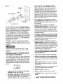
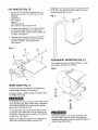
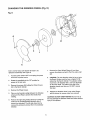
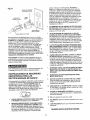
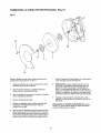
THE GRiNDiNG WHEEL (Fig. N)
Fig. N
G
M
K
\
L
H
Due to normal wear, both wheels will need to be
replaced occasionally. See Figure N
7+ Remove the Outer Wheel Flange (L) and then
remove the abrasive wheel (I) from the arbor shaft
(M)..
1o Turn the power switch "OFF" and unplug the power
cord from its power source
,,
2.. Rotate the eyeshields to the "UP" position for
access to the toot rests°
3,
Remove the screws (G) holding the Wheel Covers
(H) to the Bench Grinder+.
CAUTION: The new abrasive wheel to be put onto
the Bench Grinder must be have a higher R_PoMo
rating than the Bench Grinder° The abrasive wheel
must have a 6" diameter with a 1/2" bore diameter
for the arbor shaft+ The label on the side of the
abrasive wheels must stay on, DO NOT remove
this label..
4.+ Remove the Wheei Covers°
9+ Replace the abrasive wheel, outer wheel flange,
and the locknut in reverse order from removal+
5+ Place a small wooden wedge between the Abrasive
wheel and Tool Rest to prevent the wheels from
rotating.
.,
CAUTION: DO NOT OVER-TIGHTEN the lock nut as
this may damage the abrasive wheel and cause serious
injury to the operator_
Remove the right side grinding wheel by turning the
locknut in the counterclockwise direction with a
wrench (not included).. The left side wheel can be
removed by turning the !ocknut (K) in the clockwise
direction..
1+1