1
4. Connection with external equipment (RS-232C Interface)
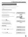
SET
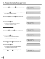
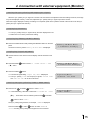
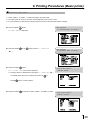
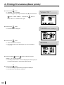
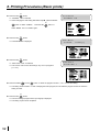
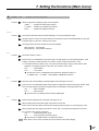
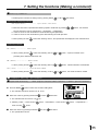
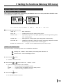
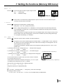
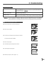
4 Press the SET
button.
, “CHANGE : OK” is selected.
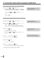
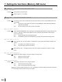
SET
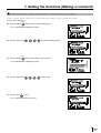
5 Select “OK”, then, press the SET
button.
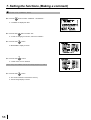
, The source image (input signal from the equipment connected) is displayed.
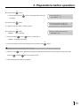
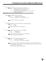
0
The setting of COMMAND TYPE is completed.
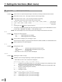
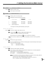
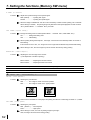
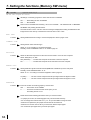
RS-232C DATA SIGNAL
RS-232C input connector port signal allocation
Pin No.
Signal line name
Description
Directions (From VCP side)
1
2
FG
TXD
Protective
Transmitted data
--Output
3
4
RXD
RTS
Received data
Request to send
Input
Output
5
6
CTS
DSR
Clear to send
Data set ready
Input
Input
7
20
GND
DTR
Signal ground
Data terminal ready
--Output
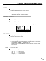
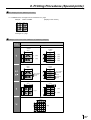
Setting the communication format of the computer
Pin connection
, Connect the unit with the host computer
through cross-over cable.
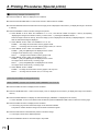
, Set the communication format as follows:
(1)
Synchronizing system
Asynchronous communication
(2)
(3)
Data bit length
Parity bit
8 bits
Nothing
(4)
(5)
STOP bit length
Transmission order
1
Sent from LSB
(6)
Baud rate (Bit / Sec)
1200, 2400, 4800, 9600
RS-232C function
, This unit can be controlled through RS-232C terminal.
( The input of image data is not possible.)
Consult with the sales dealer for the details of controlling
method (protocol).
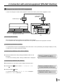
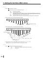
Cross-over cable
21