1
B-9000 Series
Assembly
(continued)
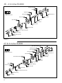
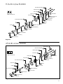
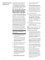
• Install the ceramic seat into the seal
housing (11) with the o-ring of the
seat away from the mechanical seal.
• Gently slide the seal housing (11)
over the drive shaft (2) until the seal
housing is in place and lined-up with
the bolt holes on the front plate (8).
• Install the socket head screws (18)
into the seal housing (11) and tighten
to the recommended torque. NOTE:
On the .05 through 9 cc/rev models,
tighten the screws using a crossing
pattern.
b) Double Lip Seal Pumps:
NOTE: The seal assembly tool (52) is
required for lip seal installation.
• The inner diameter of the lip seal
(51) must first be shaped before
installing onto the drive shaft (2).
Slide the lip seal over the seal
assembly tool (52) with the springs
of the lip seal being the last side
inserted. The lip seal should be
allowed to sit for 10-15 minutes to
allow for expansion of the lips.
• After the lips have expanded, the lip
seal (51) should be slid off of the
seal assembly tool (52), flipped
over, and then reinserted onto the
seal assembly tool so that the
springs are the first side inserted.
• Once reinserted onto the seal assembly tool (52), coat the outer rim of the
lip seal (51) with a lip seal lubricant.
• The lubricated lip seal (51) and the
seal assembly tool (52) to which it is
attached should be directed into the
seal housing (11) so that the spring
of the lip seal faces away from the
rear of the seal housing. The seal
assembly tool should be inserted
completely into the seal housing and
guided through the drive shaft hole
until the lip seal touches and is flush
with the rear wall of the seal housing.
Make sure there is no gap between
the lip seal and the seal housing.
• Place the open end of the seal
assembly tool (52) over the pump
drive shaft (2). NOTE: Make sure that
the key (17) is not in place on the drive
shaft. Slide the lip seal (51) and seal
housing (11) along the seal assembly
tool until it smoothly glides over the
drive shaft. Continue until the seal
housing is in place and lined-up with
the bolt holes on the front plate (8).
• Install the socket head screws (18)
into the seal housing (11) and tighten to the recommended torque.
NOTE: On the .05 through 9 cc/rev
models, tighten the screws using a
crossing pattern.
c) Packing Seal Pumps:
• Slide the collar plate (12) over the
drive shaft (2).
• Install four new packing rings (13)
into the packing housing (11).
• Gently slide the packing housing
(11) over the drive shaft (2). If
necessary, use the flat side of the
packing gland (14) to push the
packing housing into place to
prevent the packing rings from
being pushed out of the packing
housing.
• Use the packing gland (14) to
slightly compress the packing rings
(13) and properly position the packing housing (11).
• Remove the packing gland (14),
taking care not to move the packing
housing (11). Install the socket head
screws (18) through the packing
housing (11) and the collar plate
(12) into the front plate (8). Tighten
to the recommended torque.
• Place the packing gland (14) into
position over the packing housing
(11). Install the hex head bolts (15)
through the packing gland and
tighten finger tight.
d) Magnetically Coupled Pumps:
• Insert the smaller O-Ring into the
groove on the adapter plate, using
compatible grease to retain the
O-Ring into the groove.
• Install the plate with the O-Ring
facing the pump body using the
four socket head screws and
sealing washers.
• Insert the square key onto the pump
shaft, then slide the inner magnet
onto the shaft. Refer to certified
pump assembly drawing to determine the correct height/placement
of the magnet. NOTE: This is critical
to the pumps proper operation.
• Secure the inner magnet by
tightening the setscrew upon
the square key.
continued
13