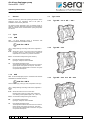
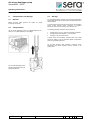
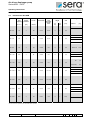
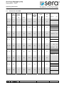
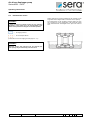
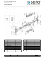
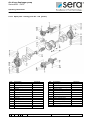
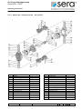
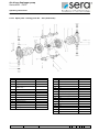
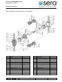
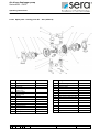
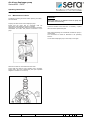
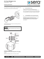
1
Air driven diaphragm pump Series APB.. / APE.. Operating instructions Product: Air driven diaphragm pump Type: ABP - 030 APB - 045 APB - 090 APB - 100 APB - 150 APB - 200.1 APB - 340 APB - 650 APB - 850 APB - 45 APE - 45 APB - 90 APE - 90 APE - 030 APE - 045 APE - 090 APE - 100 APE - 150 APE - 200.1 APE - 340 APE - 650 APE - 850 APB - 150 APE - 150 APB – 200.1 APE – 200.1 Manufacturer: APB - 340 APE - 340 sera GmbH sera-Straße 1 34376 Immenhausen Germany Tel. +49 5673 999-00 Fax. +49 5673 999-01 www.sera-web.com [email protected] TA 312 Rev. 15 en 09/2013 AP.. - 650 AP.. - 850 Subject to technical modifications! www.sera-web.com 1 Air driven diaphragm pump Series APB.. / APE.. Operating instructions Contents 1 1.1 General .................................................................... 3 Types ....................................................................... 3 1.1.1 1.1.2 1.2 Type AP.. - 30 to AP.. – 200.1 ..................................... 3 Type AP.. - 340 ............................................................. 3 Type AP.. - 650 and AP.. - 850.................................. 3 Type plate ................................................................ 4 Safety Instructions ................................................... 4 Quality Instructions .................................................. 4 Marking of Instructions ............................................. 4 Qualification and Training of Personnel ................... 4 Dangers in Case of Inobservance of the Safety Instructions ......................................... 4 3.5 Safety-Conscious Working....................................... 5 3.6 Safety Instructions for the Operator ......................... 5 3.7 Safety Instructions for Maintenance, Inspection and Installation ....................................... 5 3.8 Arbitrary Modification and Spare Parts Production .. 5 3.9 Inadmissible Operating Procedures ......................... 5 3.10 Proper Use ............................................................... 5 3.11 Personal Protection for Service and Maintenance ... 5 3.1 3.2 3.3 3.4 9.3 9.4 9.4.1 4.1 4.2 4.3 Transportation and Storage ..................................... 6 General .................................................................... 6 Transportation .......................................................... 6 Storage .................................................................... 6 5.1 5.2 5.3 5.4 Technical data.......................................................... 7 Dimensions .............................................................. 7 Performance data APB ............................................ 8 Performance data APE ............................................ 9 Performance curves ............................................... 10 4 5 5.4.1 5.4.2 5.4.3 5.4.4 5.4.5 5.4.6 5.4.7 5.4.8 5.4.9 Performance curve (AP.. - 30) ..................................... 11 Performance curve (AP.. - 45) ..................................... 11 Performance curve (AP.. - 90) ..................................... 12 Performance curve (AP.. - 100) ................................... 12 Performance curve (AP.. - 150) ................................... 13 Performance curve (AP.. – 200.1) ............................... 13 Performance curve (AP.. - 340) ................................... 14 Performance curve (AP.. - 650) ................................... 14 Performance curve (AP.. - 850) ................................... 15 Maintenance ........................................................... 21 Wearing parts ......................................................... 21 Spare parts ............................................................. 21 9.2.1 9.2.2 9.2.3 9.2.4 9.2.5 9.2.6 9.2.7 9.2.8 9.2.9 9.2.10 9.2.11 9.2.12 9.2.13 9.2.14 9.2.15 9.2.16 9.2.17 9.2.18 9.2.19 9.2.20 9.2.21 9.2.22 Type series .............................................................. 3 Medium .................................................................... 4 2 3 9.1 9.2 APB............................................................................... 3 APE............................................................................... 3 1.2.1 1.2.2 1.2.3 1.3 9 9.5 Spare parts / wearing parts AP.. - 30 (plastic) ........... 22 Spare parts / wearing parts AP.. - 30 (aluminium) ..... 23 Spare parts / wearing parts AP.. - 30 (AISI 316) ........ 24 Spare parts / wearing parts AP..- 45 (plastic) ............ 25 Spare parts / wearing parts AP..- 45 (AISI 316) .......... 26 Spare parts / wearing parts AP..- 45 (Aluminium) ...... 27 Spare parts / wearing parts AP..- 90 (plastic) ............ 28 Spare parts / wearing parts AP..- 90 (AISI 316) ......... 29 Spare parts / wearing parts AP..- 100 (plastic)........... 30 Spare parts / wearing parts AP..- 100 (Aluminium) .... 31 Spare parts / wearing parts AP..- 150 (plastic)........... 32 Spare parts / wearing parts AP..- 200.1 (plastic)........ 33 Spare parts / wearing parts AP..- 200.1 (Aluminium) . 34 Spare parts / wearing parts AP..- 340 (plastic)........... 35 Spare parts / wearing parts AP..- 340 (Aluminium) .... 36 Spare parts / wearing parts AP..- 340 (AISI 316) ....... 37 Spare parts / wearing parts AP.. - 650 (plastic).......... 38 Spare parts / wearing parts AP.. - 650 (AISI 316) ...... 39 Spare parts / wearing parts AP.. - 650 (Aluminium) ... 40 Spare parts / wearing parts AP.. - 850 (plastic).......... 41 Spare parts / wearing parts AP.. - 850 (Aluminium) ... 42 Spare parts / wearing parts AP.. - 850 (AISI 316) ...... 43 Maintenance of valves ............................................ 44 Exchange of diaphragms ........................................ 45 Diaphragm tightening torques ..................................... 46 Exchange of the control valve ................................ 46 10 De-Commissioning ................................................. 47 11 Fault Analysis and Corrective Action ...................... 47 12 Disposal .................................................................. 49 12.1 Dismounting and Transport .................................... 49 12.2 Complete Disposal ................................................. 49 13 Accessories ............................................................ 49 13.1 Compressed air supply unit(s) ................................ 49 13.2 Pulsation damper with automatic diaphragm control ....................................................... .......................................................................... 49 13.3 Stroke transmitting device ...................................... 49 Functional description ............................................ 16 6 7.1 7.2 7.3 7.4 Setup / Installation ................................................. 16 Setup...................................................................... 16 Grounding (APE-series) ......................................... 16 Connecting the lines .............................................. 17 Connecting the compressed air supply .................. 18 8.1 Commissioning ...................................................... 19 Controlling the air driven diaphragm pump ............ 20 7 8 2 www.sera-web.com Subject to technical modifications! TA 312 Rev. 15 en 09/2013 Air driven diaphragm pump Series APB.. / APE.. Operating instructions 1 1.2 General Before commissioning and while operating the sera air driven diaphragm pump the regulations valid at the place of installation must be strictly observed. Type series 1.2.1 Type AP.. - 30 to AP.. – 200.1 1.2.2 Type AP.. - 340 1.2.3 Type AP.. - 650 and AP.. - 850 The sera air driven diaphragm pump is delivered ready for operation. Carefully read these instructions and especially the safety instructions herein contained before putting the product into service. 1.1 Types 1.1.1 APB sera – air driven diaphragm pumps in accordance with directive 94/9/EWG are identified as follows: II 3G Eex c IIB T4 = Safety Markings according to DIN 40012, Appendix A II 3G: Above-floor unit for use in zones where the presence of gases, vapours or mists during pump operation is improbable or rare and in any case for a brief time. Eex-c: Constructional safety device (prEN 13463-5) IIB: Excludes the following materials: Hydrogen, acetylene, carbon disulfide T4: Permissible temperature class. The temperature classes take into account the various ignition points of the gases and vapours. This takes into account the possibility that a hot surface can ignite an explosive atmosphere. 1.1.2 APE sera - air driven diaphragm pumps in accordance with directive 94/9/EWG are identified as follows: II 2G Eex c IIB T4 Devices in Group (II), Class (2), Gas, Temperature class (T4) = Safety Markings according to DIN 40012, Appendix A II 2G: Above-floor device for use in zones with Existing gases, vapours or mists which sometimes occur during normal operation (EN 1127-1, Abs. 6.3) Eex-c: Constructional safety device (prEN 13463-5) IIB: Constructional safety device : Hydrogen, acetylene, carbon disulfide T4: Permissible temperature class. The temperature classes take into account the various ignition points of the gases and vapours. This takes into account the possibility that a hot surface can ignite an explosive atmosphere. TA 312 Rev. 15 en 09/2013 Subject to technical modifications! www.sera-web.com 3 Air driven diaphragm pump Series APB.. / APE.. Operating instructions 1.3 Type plate The type plate includes the type, serial number and the materials used. These data must be kept available for contact with sera with respect to the pump. CAUTION! Always keep these operating instructions within reach at the workplace of the pump! Type plate (example) CAUTION ! Pay attention to the safety data sheet of the medium conveyed! Take appropriate accident prevention measures to avoid that operators are endangered by the used conveying media! 3.2 Marking of Instructions Information signs which are directly attached to the pump, such as arrows indicating the direction of rotation or signs for fluid connections must be adhered to and kept in a legible condition. 3.3 2 Medium The diaphragm pump is suitable for feeding low-viscosity and viscous fluids. Please note that the flow capacity is diminished when using viscous media. Qualification and Training of Personnel The personnel who operate, maintain, carry out inspections or install the machine must be suitably qualified for their tasks. The operator has to define clearly the responsibility, and the supervision of the personnel. If the personnel do not have the required knowledge, an adequate training is to be carried out by the operator. Such a training can be realized - if required upon order of the operator of the pump by the manufacturer / supplier. The operator has to ensure furthermore that the personnel have understood the contents of the operating instructions completely. CAUTION! Flammable liquids may be fed (Note gas group and Ex zones as per Directive 94/9/EG.) APB series for use in Zone 2 only. APE series may be used also in Zone 1. The combination of ball seats and valve balls made of stainless steel is not permitted. Possible combination: Ball seats made of stainless steel and valve balls made of PTFE. CAUTION ! Personnel assigned to install, inspect and maintain must have appropriate technical training together with suitable knowledge in the field of potentially explosive atmospheres and must be aware of the associated risks! CAUTION ! 3 Safety Instructions 3.1 Quality Instructions Any use beyond the instructions in this manual will invalidate the required safety and protection properties with respect to the risk of explosion! Read these operating instructions carefully before the unit is commissioned or serviced. Observance of these operating instructions and, in particular, safety instructions, helps to Avoid danger to staff, machines, and environment. Increase the reliability and service life of the equipment and the entire installation. Reduce expenses for repairs and downtimes. 3.4 Dangers in Case of Inobservance of the Safety Instructions The inobservance of the safety instructions may result in personal injuries, hazards to the environment and damages to the pump. The sera quality management and quality assurance system for pumps, installations, fittings and compressors is certified according to ISO 9001:2008. The sera air driven diaphragm pump is compliant with the valid safety requirements and accident prevention regulations. 4 www.sera-web.com Subject to technical modifications! TA 312 Rev. 15 en 09/2013 Air driven diaphragm pump Series APB.. / APE.. Operating instructions The inobservance of the safety instructions may have the following consequences: CAUTION ! The following uses of the air driven diaphragm pumps are not permitted: 3.5 Failure of important functions of the pump/unit Failure of prescribed methods for maintenance and upkeep Danger to persons by mechanical and chemical influences Danger to the environment due to leakage of hazardous media Safety-Conscious Working The safety instructions mentioned in these operating instructions, the national regulations for accident prevention as well as all internal working-, operating and safety instructions of the operator must be observed. - Operation as a vacuum pump / generating a vacuum. Use as a shut-off fitting. Siphoning powdered products. Feeding rapidly sedimenting media. Feeding media whose chemical composition is not compatible with the pump materials. - Feeding foods. 3.10 Proper Use Safety Instructions for the Operator Use the sera air driven diaphragm pump only for the purpose indicated in the corresponding confirmation of order. Leakages (e.g. at the shaft seal) of dangerous media conveyed (e.g. explosive, poisonous, hot) must be discharged in such a way, that no dangers arise to persons or environment. The legal regulations are to be adhered to. If the pump is to be used for other purposes, it is required to consult sera beforehand to settle whether the diaphragm pump is suitable for the new usage! 3.6 Criteria for the proper use of the air driven diaphragm pump are: 3.7 Safety Instructions for Maintenance, Inspection and Installation The operator has to ensure that all maintenance, inspection and installation tasks are carried out by authorized and sufficiently qualified personnel, who have carefully read and understood the operating instructions. Only those spare parts and wearing parts are to be used that satisfy the requirements of the relevant operating conditions. Only loosen screws and connections when the system is not under pressure. 3.8 Arbitrary Modification and Spare Parts Production Modifications of or changements to the pump are only allowed after previous agreement of the manufacturer. Original spare parts and accessories that are authorized by the manufacturer are essential for safety reasons. Each claim of warranty against the operator becomes void when using non-authorized parts or modifying the diaphragm pump without anyone’s permission. 3.9 Inadmissible Operating Procedures The operational safety of the air driven diaphragm pump can only be guaranteed in case of proper use in accordance with section 3.10 of the operating instructions. Consider the characteristics of the medium conveyed (refer to the safety and product data sheet of the used medium – the safety data sheet is to be provided by the supplier/operator of the medium) Stability of the materials which have contact with the medium conveyed Operating conditions at the place of installation Pressure and temperature of the medium conveyed Control air pressure 3.11 Personal Protection for Service and Maintenance It is required to consider the recommended safety measures included in the German ordinance concerning hazardous materials (§ 14 of Safety Data Sheet) and/or the relevant national safety regulations applying to the usage of the medium conveyed. In case of accidents pay attention to the following possible emissions: Escaping of liquids and vapours Noise emissions (noise level) Emissions must be monitored by control systems of the total installation. CAUTION ! Use protective clothing, gloves, breathing mask and suitable goggles for face protection! CAUTION ! Personal protective equipment must be provided by the equipment operator at all times! TA 312 Rev. 15 en 09/2013 Subject to technical modifications! www.sera-web.com 5 Air driven diaphragm pump Series APB.. / APE.. Operating instructions 4 Transportation and Storage 4.3 4.1 General An undamaged packing protects the pump during subsequent storage and should only be opened when the diaphragm pump will be installed. Before shipment sera products are tested for proper functioning and quality. 4.2 Transportation The air driven diaphragm pump is shipped/transported in a carton or on a pallet depending on the weight Storage A proper storage will increase the service life of the diaphragm pump. Proper storage means avoidance of negative influences, such as heat, humidity, dust, chemicals etc. The following storage conditions must be observed: Storage place: cool, dry, dust-free and slightly ventilated Storage temperature between –10°C and +45°C Humidity of air not more than 50% If these values are exceeded, products made from metal should be sealed in foil and protected against condensation water using suitable dessicants. Do not store solvents, fuels, lubricants, chemicals, acids, disinfectants and similar together with the product in the storage room. The air driven diaphragm pump should be transported using an appropriate lift truck. 6 www.sera-web.com Subject to technical modifications! TA 312 Rev. 15 en 09/2013 Air driven diaphragm pump Series APB.. / APE.. Operating instructions 5 Technical data 5.1 Dimensions Dimensions Pump type AP.. - 30 AP.. - 45 m/a A B C D E F G Plastic Design G 1/2 120 165 168 136 120 6 70 AISI316 G 1/2 120 177 171 140 120 6 70 Aluminium G 1/2 120 164 172 139 124 6 70 Plastic G 1/2 153 247 241 198 168 6,5 85 AISI316 G 1/2 153 230 232 196 164 9 79 Aluminium G 1/2 153 241 234 198 168 6,5 85 AP.. - 90 AISI316 G1 170 305 271 217 214 8 93 AP.. - 100 Plastic Aluminium G1 G1 170 170 308 308 274 277 219 220 213 213 6,5 8 92 93 AP.. - 150 Plastic G1 201 329 325 263 228 8 110 AP.. - 200.1 Plastic AISI 316 Aluminium G 1 1/4 G 1 1/4 G 1 1/4 220 220 220 399 380 394 386 390 388 302 307 305 267 266 265 8 8 8 122 125 125 Plastic G 1 1/2 254 493 492 416 326 8,5 138 AISI 316 G 1 1/2 254 475 493 416 327 9,5 138 Aluminium G 1 1/2 254 479 491 415 327 8 138 200 AP.. - 340 AP.. - 650 AP.. - 850 Plastic G2 350 580 726 606 400 14 AISI 316 G2 348 470 704 582 364 11 250 Aluminium G2 350 566 621 521 364 12,5 182,5 Plastic G3 350 585 726 606 400 14 200 AISI316 G3 350 546 826 682 381 11 300 Aluminium G3 350 580 806 694 360 15 272 TA 312 Rev. 15 en 09/2013 Subject to technical modifications! www.sera-web.com 7 Air driven diaphragm pump Series APB.. / APE.. Operating instructions 5.2 Performance data APB Type APB - 30 max. flow capacity max. air supply pressure Noise Level* [ltr./min.] [bar] [dB(A)] 30 APB - 45 50 APB - 90 90 APB - 100 100 APB - 150 150 APB - 200.1 APB - 340 220 340 APB - 650 650 APB - 850 850 7 7 7 7 7 7 7 7 7 80 80 82 82 82 82 82 82 82 Control air connection G 1/4 G 3/8 G 3/8 G 3/8 G 3/8 G 1/2 G 1/2 G 1/2 G 3/4 Suction and pressure connections G 1/2 G 1/2 G1 G1 G1 G 1 1/4 G 1 1/2 G2 G3 max. suction height [m] dry 5 5 5 6 5 5 6 5 5 [m] wet 7 7 7 7 7 7 7 7 7 max. solid size [mm] Weight Material [kg] PP 1,6 PVDF-CFK 1,9 Aluminium 2 2,0 AISI 316 3,8 PP 3,6 PVDF-CFK 4,2 Aluminium 4,2 AISI 316 6,5 AISI 316 10,5 PP 5,0 PVDF-CFK 6,5 Aluminium 6,5 PP 7,5 PVDF-CFK 8,5 3,0 4,0 4,0 4,0 PP 12 PVDF-CFK 14 Aluminium 16 AISI 316 21 PP 16 PVDF-CFK 20 Aluminium 21 AISI 316 32 PP 54 PVDF-CFK 65 Aluminium 49 AISI 316 54 PP 56 PVDF-CFK 67 5,0 6,0 8,0 10,0 Aluminium AISI 316 * at 5 bar control air pressure and valve balls made of plastic 8 www.sera-web.com Subject to technical modifications! TA 312 Rev. 15 en 09/2013 Air driven diaphragm pump Series APB.. / APE.. Operating instructions 5.3 Performance data APE Type APE - 30 APE - 45 APE - 90 APE - 100 APE - 150 APE - 200.1 APE - 340 APE - 650 APE - 850 max. flow capacity max. air supply pressure Noise level [ltr./min.] [bar] [dB(A)] 30 50 90 100 150 220 340 650 850 7 7 7 7 7 7 7 7 7 80 80 82 82 82 82 82 82 82 Control air connection Suction and pressure connections G 1/4 G 1/2 G 3/8 G 1/2 G 3/8 G1 G 3/8 G1 G 3/8 G 1/2 G 1/2 G1 G 1 1/4 G 1 1/2 G 1/2 G 3/4 G2 G3 max. suction height [m] dry 5 5 5 6 5 5 6 5 5 [m] wet max. solid size [mm] 7 Material PP 1,6 PVDF-CFK 1,9 Aluminium 2 AISI 316 3,8 PP 3,6 PVDF-CFK 4,2 Aluminium 4,2 AISI 316 6,5 AISI 316 10,5 PP 5,0 PVDF-CFK 6,5 Aluminium 6,5 PP 7,5 PVDF-CFK 8,5 PP 12 PVDF-CFK 14 Aluminium 16 AISI 316 21 PP 16 PVDF-CFK 20 Aluminium 21 AISI 316 32 PP 54 3,0 7 4,0 7 4,0 7 4,0 7 5,0 7 6,0 7 PVDF-CFK 65 Aluminium 49 AISI 316 54 PP 56 PVDF-CFK 67 8,0 10,0 Aluminium AISI 316 * at 5 bar control air pressure and valve balls made of plastic TA 312 Rev. 15 en 09/2013 Subject to technical modifications! [kg] 2,0 7 7 Weight www.sera-web.com 9 Air driven diaphragm pump Series APB.. / APE.. Operating instructions 5.4 Performance curves CAUTION ! In order to achieve an optimal service life, the operating parameters of the pumps are to be approximately in the middle of the performance diagram for normal operation. = Air supply pressure = Air consumption Nl/min. Solids contents and viscous properties of the medium as well as greater suction heights lead to a reduction of the capacity. The performance curves represent average values and may vary according to pump configuration. The measured values were determined with submerged suction joints and water at 18 C. (Performance curves of single types see pages 9 – 12.) CAUTION ! When the suction and pressure lines are separate, the total capacity may be reduced by more than 50 %. 10 www.sera-web.com Subject to technical modifications! TA 312 Rev. 15 en 09/2013 Air driven diaphragm pump Series APB.. / APE.. Operating instructions 5.4.1 Performance curve (AP.. - 30) Air consumption Delivery height [metre] Air supply pressure Flow rate [litre/minute] 5.4.2 Performance curve (AP.. - 45) Luftverbrauch Delivery height [metre] Druckluftversorgung Flow rate [litre/minute] TA 312 Rev. 15 en 09/2013 Subject to technical modifications! www.sera-web.com 11 Air driven diaphragm pump Series APB.. / APE.. Operating instructions 5.4.3 Performance curve (AP.. - 90) Air consumption Delivery height [metre] Air supply pressure Flow rate [litre/minute] 5.4.4 Performance curve (AP.. - 100) Air consumption Delivery height [metre] Air supply pressure Flow rate [litre/minute] 12 www.sera-web.com Subject to technical modifications! TA 312 Rev. 15 en 09/2013 Air driven diaphragm pump Series APB.. / APE.. Operating instructions 5.4.5 Performance curve (AP.. - 150) Luftverbrauch Delivery height [metre] Druckluftversorgung Flow rate [litre/minute] 5.4.6 Performance curve (AP.. – 200.1) Luftverbrauch Delivery height [metre] Druckluftversorgung Flow rate [litre/minute] TA 312 Rev. 15 en 09/2013 Subject to technical modifications! www.sera-web.com 13 Air driven diaphragm pump Series APB.. / APE.. Operating instructions 5.4.7 Performance curve (AP.. - 340) Luftverbrauch Delivery height [metre] Druckluftversorgung Flow rate [litre/minute] Performance curve (AP.. - 650) Druckluftversorgung Luftverbrauch Delivery height [metre] 5.4.8 Flow rate [litre/minute] 14 www.sera-web.com Subject to technical modifications! TA 312 Rev. 15 en 09/2013 Air driven diaphragm pump Series APB.. / APE.. Operating instructions 5.4.9 Performance curve (AP.. - 850) Luftverbrauch Delivery height [metre] Druckluftversorgung Flow rate [litre/minute] TA 312 Rev. 15 en 09/2013 Subject to technical modifications! www.sera-web.com 15 Air driven diaphragm pump Series APB.. / APE.. Operating instructions 6 Functional description sera – Air driven diaphragm pumps are displacement pumps which can run dry with no harm to the pump. 7 Setup / Installation 7.1 Setup When setting the air driven diaphragm pumps in place, be sure that the suction and pressure connections are oriented properly. They are driven by dry, non-lubricated compressed air. The control valve ensures that the air chambers behind the diaphragms are alternatingly supplied with compressed air. CAUTION ! OUT = IN = One diaphragm is pushed to the front = Pressure stroke (A) Output Inlet (pressure side) (suction side) = = TOP ! DOWN ! and the other to the rear = Suction stroke (B). The special construction of the control valve ensures that the pumps are always driven and cannot come to an undesired stop. The valve balls open and close in stroke rhythm with the diaphragms. When installing the air driven diaphragm pump, provide for sufficient space for later maintenance work. 7.2 Grounding (APE-series) Air driven diaphragm pumps made of conductive material, which should be used for feeding flammable media, must be sufficiently grounded to prevent the risk of explosion or fire. CAUTION ! The air driven diaphragm pump must always be grounded separately from other devices. No ground or improper grounding renders the required safety regulations with respect to explosion hazard ineffective. Control valve A high-capacity ground with appropriate cable cross-section must be used! 16 www.sera-web.com Subject to technical modifications! TA 312 Rev. 15 en 09/2013 Air driven diaphragm pump Series APB.. / APE.. Operating instructions 7.3 Connecting the lines CAUTION! After setting up the air driven diaphragm pump, the suction and pressure line must be connected to the pump. CAUTION ! When installing suction and pressure lines, ensure that the materials used are resistant to the medium. The hose lines which are connected should be flexible and spiral or mesh reinforced. The inside diameter of the hose line may not be less than the nominal size at the output of the pump. Filters and other fittings installed on the suction line must be correspondingly dimensioned. When using viscous media, lines with an enlarged crosssection must be used. Connect the lines to the corresponding connection elements. A shut-off fitting (e.g. ball cock) must be installed on the pump output. The nominal size of the shut-off fitting may not be smaller than the nominal size of the pump. Be sure that the suction and pressure lines are connected to the correct points on the pump. Closing the pressure line prevents the medium from running out during maintenance work, for example. Note instructions attached to the pump: Suction side = Inlet Pressure side = Output The hose lines are to be attached using appropriate hose clamps. Install hose nozzles when connecting continuing lines (suction and pressure side). Continuing fittings are not included in the scope of delivery, but are optionally available with the sera. CAUTION ! The supply pressure may amount to several bar. The max. permissible pump pressure however must never be exceeded! TA 312 Rev. 15 en 09/2013 Subject to technical modifications! CAUTION ! Use of rigid piping may result in strong vibration and damage to the pump. www.sera-web.com 17 Air driven diaphragm pump Series APB.. / APE.. Operating instructions 7.4 Connecting the compressed air supply Recommended diameter for control air pipes: Pump type CAUTION ! The control air for supplying the air driven diaphragm pump must be dry and free of oil and solid particles. d (internal) x d (external) AP.. - 30 6x8 AP.. - 45 6x8 AP.. - 90 6x8 AP.. - 100 6x8 AP.. - 150 6x8 AP.. – 200.1 8 x 10 AP.. - 340 8 x 10 AP.. - 650 8 x 10 AP.. - 850 8 x 10 [mm] Connect the control air lines. Use care when installing to prevent undesired air loss. Filter only No oil A check valve must be installed at the compressed air terminal of the pump as illustrated. A manometer must be installed directly before the shut-off fitting to monitor the supply air pressure while the pump is running. Set the pressure of the control air so that a pressure of from 2 to 7 bar is ensured during pump operation. CAUTION ! The pressure of the control air should be less than 2 bar and not greater than 7 bar Lower pressures affect optimum function of the pump. Higher pressures will result in diaphragm rupture and increase the risk of medium leakage. As an option, sera offers a complete compressed air supply unit for the air driven diaphragm pump (see section 13 „Accessories“). (compressed air supply as per sera – Data Sheet No. 10452) Air driven diaphragm pump Check valve Compr. air press. min. 2 bar max. 7 bar Shut-off fitting Filter pressure controller 18 www.sera-web.com Subject to technical modifications! TA 312 Rev. 15 en 09/2013 Air driven diaphragm pump Series APB.. / APE.. Operating instructions When used to pump hazardous media, provide a spray guard on the air driven diaphragm pump as illustrated. Under some circumstances it can happen that the medium leaks out of the pump during and following a fault condition. Leaked medium must be collected and properly disposed of. 8 Commissioning Prior to start-up, check whether the suction and pressure lines have been properly installed. Suction side = Inlet Pressure side = Output Open the shut-off fittings on the pump (suction and pressure connection). CAUTION ! If a diaphragm rupture is not immediately recognised and aggressive media are used, it can happen that these media enter the air circuit and are blown into the environment through the air outlet (noise absorber). If not protective measure is installed: RISK OF SEVERE HEALTH AND ENVIRONMENTAL CONSEQUENCES! TA 312 Rev. 15 en 09/2013 Subject to technical modifications! www.sera-web.com 19 Air driven diaphragm pump Series APB.. / APE.. Operating instructions Verify correct installation of the control lines (shut-off fitting, check valve). The air driven diaphragm pump should be stopped only by means of the control air supply. Open the shut-off fitting on the compressed air connection. CAUTION ! Never stop a running or pressurised pump by closing the shut-off fittings on the suction connection of the pump. This will damage the pump (diaphragm rupture). CAUTION ! Feeding liquids having higher viscosity requires that: ...the suction line be properly designed and dimensioned. ...the stroke number of the pump be reduced by restricting the control air volume (at constant pressure). After two running hours the pump should be properly stopped and secured against accidental restarting. Now check and if necessary correct all fittings for tight sealing. Once all fittings are correctly tightened, the pump is ready for operation (including continuous operation). Check and set the air pressure at the filter pressure controller while the pump is running: min. 2 bar max. 7 bar 8.1 Controlling the air driven diaphragm pump The stroke number and thereby the pump capacity can be set using the pressure regulator for the control air. Be sure that the pressure is not restricted to less than 2 bar. Regulating using the filter pressure controller also reduces the control air requirement. 20 www.sera-web.com Subject to technical modifications! TA 312 Rev. 15 en 09/2013 Air driven diaphragm pump Series APB.. / APE.. Operating instructions 9 Maintenance CAUTION ! CAUTION ! All maintenance work must be performed only with a de-pressurised system. This applies to the suction and pressure line as well as to the control air. When installing or assembling the pump, it must always be kept level. Otherwise there is a risk that leaks from fasteners and connectors on metal lines will leak. Properly stop the pump, let out the medium and close the shut-off fittings. 9.1 Wearing parts The wear parts must be regularly replaced depending on how and how long they have been used to ensure reliable functioning of the air driven diaphragm pump. We recommend inspection and replacement of the diaphragms after: 20 mil. 10 mil. Strokes when aggressive media are used Strokes when abrasive media are used* or at least once a year. Bring the pressure of the control air down to near zero and ensure that there is no residual pressure, close the shut-off fitting in the control air line * Please note that these are only rough guidelines. When strongly abrasive media are used, increased wear of the diaphragms will occur in a much shorter time. To monitor the number of strokes, we offer an optional stroke counter (see section 13 „Accessories“). If more severe operating conditions result in premature diaphragm rupture, the air driven diaphragm pump must be properly shut down (see section 8.1) and the diaphragm replaced as described in section 9.4. Wear parts on the air driven diaphragm pump include: 0 bar 9.2 Diaphragms Valve balls Valve seats Valve seals Spare parts Spare parts for the air driven diaphragm pump include the: CAUTION ! Control valve Whenever performing work on the system, be sure that you have the necessary wear and/or spare parts available before starting your work. Handle and store removed parts carefully to prevent damage. CAUTION ! All wear parts must be checked at regular intervals for optimum condition and replaced as necessary. TA 312 Rev. 15 en 09/2013 Subject to technical modifications! www.sera-web.com 21 Air driven diaphragm pump Series APB.. / APE.. Operating instructions 9.2.1 Pos. Spare parts / wearing parts AP.. - 30 (plastic) Designation Article-No. Pos. Designation Article-No. 1 Motor housing 18 Blind plug 3 Pump body 20 Screw, air outlet cover 4 Common piping 22 Air outlet cover 5 Ball seat 26 Screw, pump body 5b Ball guide 28 Screw, common piping 6 Connection rod 29 Disc 7 Sound absorber 41 Shuttle distributor 8 Pressure plate 42 Cap shuttle gasket 9 Spring washer 43 Cap shuttle 10 Diaphragm fixing 44 Control valve 11 Valve ball 12 Diaphragm, internal 13 Diaphragm, external 14 Square nut 16 Snap ring 17 Valve seal 17a Valve seal 22 www.sera-web.com Subject to technical modifications! TA 312 Rev. 15 en 09/2013 Air driven diaphragm pump Series APB.. / APE.. Operating instructions 9.2.2 Pos. Spare parts / wearing parts AP.. - 30 (aluminium) Designation Article-No. Pos. Designation 1 Motor housing 20 Screw, air outlet cover 3 Pump body 22 Air outlet cover 4 Common piping 26 Screw, pump body 5 Ball seat 28 Screw, common piping 5b Ball guide 29 Disc 6 Connection rod 41 Shuttle distributor 7 Sound absorber 42 Cap shuttle gasket 8 Pressure plate 43 Cap shuttle 44 Control valve 9 Spring washer 10 Diaphragm fixing 11 Valve ball 12 Diaphragm, internal 13 Diaphragm, external 14 Square nut 16 Snap ring 17 Valve seal 17a Valve seal TA 312 Rev. 15 en 09/2013 Subject to technical modifications! www.sera-web.com Article-No. 23 Air driven diaphragm pump Series APB.. / APE.. Operating instructions 9.2.3 Pos. Spare parts / wearing parts AP.. - 30 (AISI 316) Designation Article-No. Pos. Designation Article-No. 1 Motor housing 18 Blind plug 3 Pump body 20 Screw, air outlet cover 4 Common piping 22 Air outlet cover 5 Ball seat 26 Screw, pump body 5b Ball guide 28 Screw, common piping 6 Connection rod 29 Disc 7 Sound absorber 41 Shuttle distributor 8 Pressure plate 42 Cap shuttle gasket 9 Spring washer 43 Cap shuttle 10 Diaphragm fixing 44 Control valve 11 Valve ball 12 Diaphragm, internal 13 Diaphragm, external 14 Square nut 16 Snap ring 17 Valve seal 17a Valve seal 24 www.sera-web.com Subject to technical modifications! TA 312 Rev. 15 en 09/2013 Air driven diaphragm pump Series APB.. / APE.. Operating instructions 9.2.4 Pos. Spare parts / wearing parts AP..- 45 (plastic) Designation Article-No. Pos. Designation 1 Motor housing 22 Air outlet cover 3 Pump body 23 Nut 4 Common piping 26 Screw, pump body 5 Ball seat 27 Seal, blind plug 6 Connection rod 28 Screw, common piping 7 Sound absorber 33 O-ring 8 Pressure plate 40 Reset valve 9 Spring washer 10 Diaphragm fixing 11 Valve ball 12 Diaphragm, internal 13 Diaphragm, external 14 Square nut 16 Snap ring 17 Valve seal 18 Blind plug 19 Control valve T20 20 Screw, air outlet cover TA 312 Rev. 15 en 09/2013 Subject to technical modifications! www.sera-web.com Article-No. 25 Air driven diaphragm pump Series APB.. / APE.. Operating instructions 9.2.5 Pos. Spare parts / wearing parts AP..- 45 (AISI 316) Designation Article-No. Pos. Designation Article-No. 1 Motor housing 16 Snap ring 3 Pump body 17 Valve seal 4 Common piping 18 Blind plug 5 Ball seat 19 Contro valve T20 6 Connection rod 20 Screw, air outlet cover 7 Sound absorber 22 Air outlet cover 8 Pressure plate 23 Nut 9 Spring washer 26 Screw, pump body 10 Diaphragm fixing 27 Seal, blind plug 11 Valve ball 28 Screw, common piping 12 Diaphragm, internal 40 Reset Valve 13 Diaphragm, external 26 www.sera-web.com Subject to technical modifications! TA 312 Rev. 15 en 09/2013 Air driven diaphragm pump Series APB.. / APE.. Operating instructions 9.2.6 Pos. Spare parts / wearing parts AP..- 45 (Aluminium) Designation Article-No. Pos. Designation 1 Motor housing 16 Snap ring 3 Pump body 17 Valve seal 4 Common piping 18 Blind plug 5 Ball seat 19 Contro valve T20 6 Connection rod 20 Screw, air outlet cover 7 Sound absorber 22 Air outlet cover 8 Pressure plate 23 Nut 9 Spring washer 26 Screw, pump body 10 Diaphragm fixing 27 Seal, blind plug 11 Valve ball 28 Screw, common piping 12 Diaphragm, internal 40 Reset Valve 13 Diaphragm, external TA 312 Rev. 15 en 09/2013 Subject to technical modifications! www.sera-web.com Article-No. 27 Air driven diaphragm pump Series APB.. / APE.. Operating instructions 9.2.7 Pos. Spare parts / wearing parts AP..- 90 (plastic) Designation Article-No. Pos. Designation Article-No. 1 Motor housing 16 Snap ring 3 Pump body 17 Valve seal 4 Common piping 18 Blind plug 5 Ball seat 19 Contro valve T20 6 Connection rod 20 Screw, air outlet cover 7 Sound absorber 22 Air outlet cover 8 Pressure plate 23 Nut Screw, pump body 9 Spring washer 26 10 Diaphragm fixing 27 Seal, blind plug 11 Valve ball 28 Screw, common piping 12 Diaphragm, internal 33 O-ring 13 Diaphragm, external 40 Reset Valve 14 Square nut 28 www.sera-web.com Subject to technical modifications! TA 312 Rev. 15 en 09/2013 Air driven diaphragm pump Series APB.. / APE.. Operating instructions 9.2.8 Pos. Spare parts / wearing parts AP..- 90 (AISI 316) Designation Artikel-Nr. Pos. Designation 1 Motor housing 16 Snap ring 3 Pump body 17 Valve seal 4 Common piping 18 Blind plug 5 Ball seat 19 Contro valve T20 6 Connection rod 20 Screw, air outlet cover 7 Sound absorber 22 Air outlet cover 8 Pressure plate 23 Nut 9 Spring washer 26 Screw, pump body 10 Diaphragm fixing 27 Seal, blind plug 11 Valve ball 28 Screw, common piping 12 Diaphragm, internal 33 O-ring 13 Diaphragm, external 40 Reset valve 14 Square nut TA 312 Rev. 15 en 09/2013 Subject to technical modifications! www.sera-web.com Artikel-Nr. 29 Air driven diaphragm pump Series APB.. / APE.. Operating instructions 9.2.9 Pos. Spare parts / wearing parts AP..- 100 (plastic) Designation 01 Motor housing 03 04 Article-No. Pos. Designation Article-No. 16 Snap ring Pump body 17 lower valve seal Common piping 17a upper valve seal 05 Ball seat 18 Blind plug 5b Ball guide 19 Control valve T20 06 Connection rod 20 Screw, air outlet cover 07 Sound absorber 21 Spacer 08 Pressure plate 22 Air outlet cover 09 Spring washer 23 Nut 10 Diaphragm fixing 26 Screw, pump body 11 Valve ball 27 Seal, blind plug 12 Diaphragm, internal 28 Screw, common piping 13 Diaphragm, external 19 Disk 14 Square nut 32 Reset valve 30 www.sera-web.com Subject to technical modifications! TA 312 Rev. 15 en 09/2013 Air driven diaphragm pump Series APB.. / APE.. Operating instructions 9.2.10 Spare parts / wearing parts AP..- 100 (Aluminium) Pos. Designation Article-No. Pos. Designation 1 Motor housing 14 Square nut 3 Pump body 16 Snap ring 4 Common piping 17 Valve seat 5 Ball seat 18 Blind plug 6 Connection rod 19 Control valve T20 7 Sound absorber 20 Screw, air outlet cover 8 Pressure plate 22 Air outlet cover 9 Spring washer 23 Nut 10 Diaphragm fixing 26 Screw, pump body 11 Valve ball 27 Seal, blind plug 12 Diaphragm, internal 28 Screw, common piping 13 Diaphragm, external 40 Reset Valve TA 312 Rev. 15 en 09/2013 Subject to technical modifications! www.sera-web.com Article-No. 31 Air driven diaphragm pump Series APB.. / APE.. Operating instructions 9.2.11 Spare parts / wearing parts AP..- 150 (plastic) Pos. Designation Article-No. Pos. Designation Article-No. 1 Motor housing 16 Snap ring 3 Pump body 17 Valve seal 4 Common piping 18 Blind plug 5 Ball seat 19 Contro valve T20 Screw, air outlet cover 5b Ball guide 20 6 Connection rod 22 Air outlet cover 7 Sound absorber 23 Nut 8 Pressure plate 26 Screw, pump body 9 Spring washer 27 Seal, blind plug 10 Diaphragm fixing 28 Screw, common piping 11 Valve ball 40 Reset valve 12 Diaphragm, internal 13 Diaphragm, external 32 www.sera-web.com Subject to technical modifications! TA 312 Rev. 15 en 09/2013 Air driven diaphragm pump Series APB.. / APE.. Operating instructions 9.2.12 Spare parts / wearing parts AP..- 200.1 (plastic) Pos. Designation Article-No. Pos. Designation 1 Motor housing 16 Snap ring 3 Pump body 17 Valve seal 4 Common piping 18 Blind plug 5 Ball seat 19 Control valve T30 6 Connection rod 20 Screw, sound absorber grid 8 Pressure plate 22 Sound absorber grid 9 Spring washer 23 Nut 10 Diaphragm fixing 26 Screw, pump body 11 Valve ball 27 Seal, blind plug 12 Diaphragm, internal 28 Screw, common piping 13 Diaphragm, external 30 Distance ring 14 Nut 40 Reset valve 15 Sound absorber filter TA 312 Rev. 15 en 09/2013 Subject to technical modifications! www.sera-web.com Article-No. 33 Air driven diaphragm pump Series APB.. / APE.. Operating instructions 9.2.13 Spare parts / wearing parts AP..- 200.1 (Aluminium) Pos. Designation Article-No. Pos. Designation Article-No. 1 Motor housing 16 Snap ring 3 Pump body 17 Valve seal 4 Common piping 18 Blind plug 5 Ball seat 19 Control valve T30 6 Connection rod 20 Screw, sound absorber grid 8 Pressure plate 22 Sound absorber grid 9 Spring washer 23 Nut 10 Diaphragm fixing 26 Screw, pump body 11 Valve ball 27 Seal, blind plug 12 Diaphragm, internal 28 Screw, common piping 13 Diaphragm, external 30 Distance ring 14 Nut 40 Reset valve 15 Sound absorber filter 34 www.sera-web.com Subject to technical modifications! TA 312 Rev. 15 en 09/2013 Air driven diaphragm pump Series APB.. / APE.. Operating instructions 9.2.14 Spare parts / wearing parts AP..- 340 (plastic) Pos. Designation Article-No. Pos. Designation 1 Motor housing 18 Blind plug 3 Pump body 19 Control valve T30 4 Common piping 20 Screw, sound absorber grid 5 Ball seat 21 Distance sleeve 6 Connection rod 22 Sound absorber grid 8 Pressure plate 23 Nut 9 Spring washer 26 Screw, pump body 10 Diaphragm fixing 27 Seal, blind plug 11 Valve ball 28a Screw, common piping 12 Diaphragm, internal 28b Scew, common piping 13 Diaphragm, external 29 Disc 15 Sound absorber filter 30 Distance ring 16 Snap ring 40 Reset valve 17 Valve seal TA 312 Rev. 15 en 09/2013 Subject to technical modifications! www.sera-web.com Article-No. 35 Air driven diaphragm pump Series APB.. / APE.. Operating instructions 9.2.15 Spare parts / wearing parts AP..- 340 (Aluminium) Pos. Designation Article-No. Pos. Designation Article-No. 1 Motor housing 17 Valve seal, internal 3 Pump body 17a Valve seal, external 4 Common piping 18 Blind plug Control valve T30 5 Ball seat 19 5b Ball guide 20 Screw, sound absorber grid 6 Connection rod 22 Sound absorber grid 8 Pressure plate 23 Nut 9 Spring washer 26 Screw, pump body 10 Diaphragm fixing 27 Seal, blind plug 11 Valve ball 28a Screw, common piping 12 Diaphragm, internal 28b Screw, common piping 13 Diaphragm, external 29 Disc 15 Sound absorber filter 30 Distance ring 16 Snap ring 40 Reset valve 36 www.sera-web.com Subject to technical modifications! TA 312 Rev. 15 en 09/2013 Air driven diaphragm pump Series APB.. / APE.. Operating instructions 9.2.16 Spare parts / wearing parts AP..- 340 (AISI 316) Pos. Designation Article-No. Pos. Designation 1 Motor housing 17 3 Pump body 17a Valve seal, external 4 Common piping 18 Blind plug Control valve T30 5 Ball seat 19 5b Ball guide 20 Screw, sound absorber grid 6 Connection rod 22 Sound absorber grid 8 Pressure plate 23 Nut 9 Spring washer 26 Screw, pump body 10 Diaphragm fixing 27 Seal, blind plug 11 Valve ball 28a Screw, common piping 12 Diaphragm, internal 28b Screw, common piping 13 Diaphragm, external 29 Disc 15 Sound absorber filter 30 Distance ring 16 Snap ring 40 Reset valve TA 312 Rev. 15 en 09/2013 Subject to technical modifications! Article-No. Valve seal, internal www.sera-web.com 37 Air driven diaphragm pump Series APB.. / APE.. Operating instructions 9.2.17 Spare parts / wearing parts AP.. - 650 (plastic) Pos. Designation Article-No. Pos. Designation Article-No. 1 Ball seat 19 Spring washer 2 Ball seat O-ring, below 21 Flange 2a Ball seat O-ring, above 22 Spring washer 4 Disc 23 Disc 5a Ball seat 24 Screw 5b Ball guide 25 Screw, common pipe, press.side 6 Nut 26 Common piping, pressure side 7 Pump body 27 Nut 8 Disc 28 Motor housing 9 Screw, pump body 29 Control valve T40 11 Pressure plate 30 Connection rod 13 Diaphragm, external 32 Sound absorber 14 Diaphragm, internal 33 Common piping, suction side 15 Diaphragm fixing 35 Screw, common pipe, suction side 38 www.sera-web.com Subject to technical modifications! TA 312 Rev. 15 en 09/2013 Air driven diaphragm pump Series APB.. / APE.. Operating instructions 9.2.18 Spare parts / wearing parts AP.. - 650 (AISI 316) Pos. 1 Designation Article-No. Pos. Designation Main block 17 2 Flange 17a Valve seal, internal 3 Pump body 19 Control valve 4a Common piping (suction line) 21 Distance sleeve 23 Nut Common piping (pressure line) 25 Screw 26 Screw, pump body 28 Screw, common pipe, suct. side 4b 5 Ball seat 5b Ball guide 6 Connection rod 7 Silencer 8 Pressure plate 9 Spring washer 10 Diaphragm fixing 11 Ball 12 Diaphragm, internal 13 Diaphragm, external TA 312 Rev. 15 en 09/2013 Subject to technical modifications! Article-No. Valve seal, external 29 Joint, common pipe, suct. side. 37 Disc 46 Screw 47 Nut 48 Pin 49 Silencer extension 50 Air connec. extension www.sera-web.com 39 Air driven diaphragm pump Series APB.. / APE.. Operating instructions 9.2.19 Spare parts / wearing parts AP.. - 650 (Aluminium) Pos. 1 Designation Article-No. Pos. Designation Article-No. Main block 17 Valve seal, internal 2 Flange 17a Valve seal, external 3 Pump body 19 Control valve 4 Common piping (suction line) 21 Distance sleeve 23 Nut 5 Ball seat 25 Screw 5b Ball guide 26 Screw, pump body 6 Connection rod 28 Screw, common pipe, suct. side 7 Silencer 29 Joint, common pipe, suct. side. 8 Pressure plate 37 Disc 9 Spring washer 38 Spring washer 10 Diaphragm fixing 40 Silencer extension 11 Ball 47 Air connec. extension 12 Diaphragm, internal 49 Nut 13 Diaphragm, external 50 Pin 51 Screw 52 Adapter-Label 40 www.sera-web.com Subject to technical modifications! TA 312 Rev. 15 en 09/2013 Air driven diaphragm pump Series APB.. / APE.. Operating instructions 9.2.20 Spare parts / wearing parts AP.. - 850 (plastic) Pos. Designation Article-No. Pos. Designation 1 Ball seat 19 Spring washer 2 Valve seal, external 21 Flange 2a Valve seal, internal 22 Spring washer 4 Disc 23 Disc Screw 5a Ball seat 24 5b Ball guide 25 Screw, common pipe, press.side 6 Nut 26 Common piping, pressure side 7 Pump body 27 Nut 8 Disc 28 Motor housing 9 Screw, pump body 29 Control valve T40 11 Pressure plate 30 Connection rod 13 Diaphragm, external 32 Sound absorber 14 Diaphragm, internal 33 Common piping, suction side 15 Diaphragm fixing 35 Screw, common pipe, suction side TA 312 Rev. 15 en 09/2013 Subject to technical modifications! www.sera-web.com Article-No. 41 Air driven diaphragm pump Series APB.. / APE.. Operating instructions 9.2.21 Spare parts / wearing parts AP.. - 850 (Aluminium) Pos. 1 Designation Article-No. Pos. Designation Article-No. Main block 17 Valve seal 2 Flange 19 Control valve 3 Pump body 21 Distance sleeve 4 Common piping (suction line) 23 Nut 25 Screw 5 Ball seat 26 Screw, pump body 6 Connection rod 28 Screw, common pipe, suct. side 7 Silencer 29 Joint, common pipe, suct. side. 8 Pressure plate 37 Disc Spring washer 9 Spring washer 38 10 Diaphragm fixing 50 Pin 11 Ball 51 Screw 12 Diaphragm, internal 52 Adapter-Label 13 Diaphragm, external 42 www.sera-web.com Subject to technical modifications! TA 312 Rev. 15 en 09/2013 Air driven diaphragm pump Series APB.. / APE.. Operating instructions 9.2.22 Spare parts / wearing parts AP.. - 850 (AISI 316) Pos. Designation Article-No. Pos. Designation 1 Main block 17 Ball seat O-ring 2 Flange 19 Control valve 3 Pump body 21 Distance sleeve 4a Common piping (suction line) 23 Nut 25 Screw 4b Common piping (pressure line) 26 Screw, pump body 28 Screw, common pipe, suct. side 29 Joint, common pipe, suct. side. 5 Ball seat 6 Connection rod 7 Silencer 8 Pressure plate 9 Spring washer 10 Diaphragm fixing 11 Ball 12 Diaphragm, internal 13 Diaphragm, external TA 312 Rev. 15 en 09/2013 Subject to technical modifications! 37 Disc 45 Foot 46 Screw 47 Nut 50 Pin 51 Screw 52 Adapter-Label www.sera-web.com Article-No. 43 Air driven diaphragm pump Series APB.. / APE.. Operating instructions 9.3 Maintenance of valves Procedure for cleaning the valves and/or replacing valve balls and valve seats: Properly shut down the air driven diaphragm pump. Ensure that the pump and its connection lines are pressureless, and release the pressure if needed. Observing the corresponding safety and protection measures, disassemble the suction and pressure connections on the pump. CAUTION ! Ensure that there are no deposits inside the pump, and clean these out if necessary. Check the condition of the seals and – if necessary – replace them with exact replacement parts. After cleaning/replacing the valves/seals, reinstall the pump in reverse order. The connections are made as described in the preceding sections. The air driven diaphragm pump is now ready to use again. Remove and clean the valve balls and valve seats. Inspect balls and seats for their condition and if necessary replace them with exact replacement parts (see exploded diagrams in sections 9.2.1 to 9.2.12) 44 www.sera-web.com Subject to technical modifications! TA 312 Rev. 15 en 09/2013 Air driven diaphragm pump Series APB.. / APE.. Operating instructions 9.4 Loosen and remove the diaphragm fasteners. Exchange of diaphragms CAUTION ! All work to be performed only on a pressureless system ! For flawless function of the air driven diaphragm pump and to maintain the required safety and protection characteristics – especially in explosion hazard areas – the drive diaphragms must be regularly inspected and replaced. For maintenance intervals pertaining to the diaphragms, see section 9.1 „Wear parts“. Procedure for changing diaphragms: Properly shut down the air driven diaphragm pump. Ensure that the pump and its connection lines are pressureless, and release the pressure if needed. Disassemble the suction and pressure connections from the pump while observing the corresponding safety and protection measures. Remove the diaphragms and check their condition. After the prescribed interval has elapsed (see section 9.1) or when there is evidence of wear, the diaphragms must be replaced. We recommend that both diaphragm packages be replaced at the same time. Disassemble the suction and pressure channel of the pump. CAUTION ! Ensure that there are no deposits inside the pump, and clean these out if necessary. CAUTION ! Loosen the mounting screws and remove both pump housings. The parts comprising the control valve, including the shaft, are not resistant to chemical attack. If the control valve has come into contact with the medium following a diaphragm break, the control valve must be replaced as described in section 9.5. Reassemble the air driven diaphragm pump in reverse order. Observe tightening torques for attaching the diaphragm! (see section 9.4.1 „Diaphragm tightening torques“) Tighten the mounting screws evenly. Connect the suction and pressure lines. Connect the compressed air supply. The air driven diaphragm pump is now ready to use again. TA 312 Rev. 15 en 09/2013 Subject to technical modifications! www.sera-web.com 45 Air driven diaphragm pump Series APB.. / APE.. Operating instructions 9.4.1 Diaphragm tightening torques 9.5 Proceed as follows to replace the control valve. Diaphragm tightening torques Pump model Diaphragm material Tightening torque [Nm] AP.. - 30 Santoprene Santoprene + PTFE Hytrel Hytrel + PTFE 15 15 15 15 AP.. - 45 Santoprene Hytrel + PTFE 27 30 AP.. - 90 Santoprene Hytrel + PTFE 30 33 AP.. - 100 Santoprene Hytrel + PTFE 30 33 AP.. - 150 Santoprene Santoprene + PTFE Hytrel + PTFE 33 33 33 AP.. – 200.1 Santoprene Santoprene + PTFE Hytrel + PTFE 37 40 40 AP.. - 340 Santoprene Hytrel + PTFE 47 50 AP.. - 650 Santoprene Santoprene + PTFE Hytrel + PTFE 160 160 160 AP.. - 850 Santoprene Santoprene + PTFE Hytrel + PTFE 160 160 160 46 www.sera-web.com Exchange of the control valve Disassemble the pump as described in section 9.3 „Changing diaphragms“. Subject to technical modifications! TA 312 Rev. 15 en 09/2013 Air driven diaphragm pump Series APB.. / APE.. Operating instructions Use a suitable tool to remove the control valve security rings and remove the control valve from the drive housing. 10 De-Commissioning Properly shut down the air driven diaphragm pump. (see section 8.1 „Controlling the air driven diaphragm pump“) Flush out the medium from the pump using a flushing medium which is appropriate to the medium and pump head material. 11 Fault Analysis and Corrective Action sera products are proven technical products which are only shipped after an extensive final test in our works. Should any malfunctions occur, these can be located and corrected easily with the help of the reference guide (see page 35). Carefully replace the control valve and connecting rod with an original replacement part. CAUTION ! Note correct installation orientation of the control valve! (see illustration) Reassemble in reverse order. You are now finished replacing the control valve and the connections can be made as described in the preceding sections. The air driven diaphragm pump is now ready to operate. TA 312 Rev. 15 en 09/2013 Subject to technical modifications! www.sera-web.com 47 Air driven diaphragm pump Series APB.. / APE.. Operating instructions Fault Pump will not start Pump runs, but no feeding action Pump does not run evenly Pump stops Pump not at the capacity indicated in the table (characteristic curve) Possible cause Remedy Compressed air supply out of commission Check compressed air supply, shut-off fittings and connections. Insufficient control air pressure Set pressure on the corresponding controller Insufficient control air flow Check whether the tubes (hoses) accessories have the proper nominal sizes Filter pressure controller (control air supply) damaged Inspect, replace as needed. Pump inlet or output closed Loosen the suction and control line and check whether the pump starts. Control valve damaged Replace control valve; check whether there is icing on the air outlet (noise absorber), if yes: remove Viscosity of medium too high Cannot be remedied Compressed air line blocked Check and clean Suction line blocked Check and clean Diaphragm(s) broken Check whether air exits the pump on the pressure side; if yes: replace diaphragms. Valve balls are not closing Clean valve balls and seats, replace as needed. Suction pressure too high Reduce suction pressure. Suction line blocked Check and clean. Viscosity of the medium too high Install lines with a larger nominal size, especially on the suction side. Reduce pump speed (stroke number). Pump control valve damaged or defective Replace control valve. Ice on the air outlet (noise absorber) Dry and filter the control air. No control air flow Check compressed air supply accessories, in particular any quick-connects Suction line blocked while running Clean suction line and/or provide a suitable filter. Control air contaminated with condensed water or oil Check control air line and clean as needed. Use only dry, oil- and solid particle-free air. Clean control valve and replace as needed Insufficient control air flow or pressure Check control air pressure using a manometer installed on the pump. If the pressure at this point is lower with respect to the supply pressure, check all control air connections. Check all control air components for proper dimensioning. Check control air lines for proper sealing. Filter pressure controller defective Replace filter pressure controller. Suction line is not properly connected or sealed Suction line is not correctly installed. Check and correct as needed. Lines plugged Check and clean. Viscosity of the medium too high Install larger lines, especially on the suction side. Reduce the pump speed (stroke number). Valve balls do not close Clean valve balls and seats, replace as needed. Insufficient control air flow Check control air pressure using a manometer installed on the pump. If the pressure at this point is lower with respect to the supply pressure, check all control air connections. Check all control air components for proper dimensioning. Check control air lines for proper sealing. and Install pulsation dampers. Suction and/or pressure line too long with insufficient Pressure side: Series MPD-... line cross-section Suction side: Series 702.1 resp. 802.1 + ff. 48 www.sera-web.com Subject to technical modifications! TA 312 Rev. 15 en 09/2013 Air driven diaphragm pump Series APB.. / APE.. Operating instructions 12 Disposal 13.2 Pulsation damper with automatic diaphragm control Switch the unit off, refer to “Decommissioning”. 12.1 Dismounting and Transport sera - diaphragm pulsation dampers with automatic diaphragm control ensure relatively even flow and reduce pressure spikes which can result in undesired oscillations in the piping system. Remove all remaining fluid, clean, neutralise and decontaminate the device carefully. Pack the device properly and arrange everything for transport. 12.2 Complete Disposal Remove all remaining fluid out of the unit. Dismount all materials and send them to a suitable processing company. CAUTION The consignor is liable for any defects resulting from leaking lubricants or residual fluids! MPD - 25.1 . . . MPD - 850 The diaphragm pulsation damper is installed in the bypass for the pump compressed air supply. No preloading or manual setting is necessary. The pulsation damper automatically adjusts to the operating conditions. 13 Use series MPD-.... pulsation dampers on the pump pressure side, and series 702.1 resp. 802.1 + ff. on the suction side. Accessories 13.1 Compressed air supply unit(s) sera - offers an optional compressed air supply unit for the air driven diaphragm pump. Contact sera - sales to request a data sheet and additional information (Data Sheet No. 10450 and 10451 (MPD650)). 13.3 Stroke transmitting device The stroke counter can be integrated in the drive housing of the air driven diaphragm pump. It generates a signal for each stroke executed by the pump, which can be electronically processed. (non applicable to type APB - 650 and APB – 850) The components of the compressed air supply units are tune to each other to facilitate operation of the air driven diaphragm pumps and reduce the risk of operating failures due to control air supply problems. Ask the sera sales department for an informative data sheet (Data Sheet No. 10452 and 10527). TA 312 Rev. 15 en 09/2013 Subject to technical modifications! Along with a stroke counter the sera - air driven diaphragm pump can also be used for charge dosing. A stroke counter also assists in timely maintenance for the pump (e.g. inspecting/replacing the diaphragms). www.sera-web.com 49 Air driven diaphragm pump Series APB.. / APE.. Operating instructions Notes 50 www.sera-web.com Subject to technical modifications! TA 312 Rev. 15 en 09/2013 Air driven diaphragm pump Series APB.. / APE.. Operating instructions Notes TA 312 Rev. 15 en 09/2013 Subject to technical modifications! www.sera-web.com 51 Air driven diaphragm pump Series APB.. / APE.. Operating instructions 52 www.sera-web.com Subject to technical modifications! TA 312 Rev. 15 en 09/2013