1
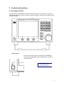
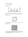
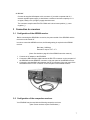
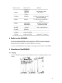
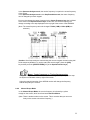
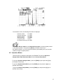
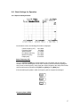
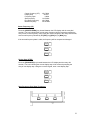
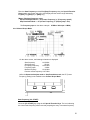
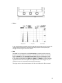
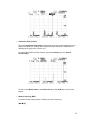
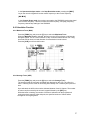
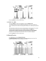
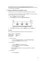
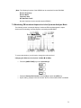
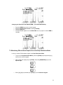
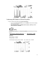
SDU5600
PROFESSIONAL SPECTRUM DISPLAY UNIT
FOR USE WITH A COMPANION RECEIVER
INSTRUCTION MANUAL
AOR, LTD.
Downloaded by
Amateur Radio Directory
www.hamdirectory.info
TABLE OF CONTENTS
1
Index
------------------------------------------------------------------------------------------------ 1
1-1 Introduction -------------------------------------------------------------------------------------- 2
1-2 Taking care of the unit ------------------------------------------------------------------------ 2
1-3 Power requirements --------------------------------------------------------------------------- 2
1-4 Supplied accessories ------------------------------------------------------------------------- 3
1-5 Features ------------------------------------------------------------------------------------------ 3
2 Control and functions ------------------------------------------------------------------------------ 4
2-1 Front panel controls ---------------------------------------------------------------------------- 4
2-2 Rear Panel --------------------------------------------------------------------------------------- 6
3 Connection to a receiver ---------------------------------------------------------------------------- 7
3-1 Configuration of the AR5000 receiver ----------------------------------------------------- 7
3-2 Configuration of the companion receiver(s) ---------------------------------------------- 7
4 Switch on the SDU5600 ---------------------------------------------------------------------------- 8
5 Operations of the SDU5600 ------------------------------------------------------------------------ 8
5-1 Display ---------------------------------------------------------------------------------------------- 8
5-2 Main Control Keys ------------------------------------------------------------------------------ 10
5-3 Default mode ------------------------------------------------------------------------------------- 10
5-4 When the communication is disconnected from the receiver ------------------------- 11
6 Settings ----------------------------------------------------------------------------------------------------- 11
6-1 Configuration menu ----------------------------------------------------------------------------- 11
6-2 Companion receivers --------------------------------------------------------------------------- 12
6-3 Receiver settings --------------------------------------------------------------------------------- 12
6-4 Controlling the receive frequency ------------------------------------------------------------ 13
6-4-1 Spectrum analyzer mode ------------------------------------------------------------------ 13
6-4-2 Channel scope mode ------------------------------------------------------------------------ 14
6-5 Operation modes -------------------------------------------------------------------------------- 15
6-6 Basic settings for operation -------------------------------------------------------------------- 17
6-6-1 Spectrum analyzer mode ------------------------------------------------------------------- 17
6-6-2 Step resolution mode ------------------------------------------------------------------------ 18
6-6-3 Channel scope mode ------------------------------------------------------------------------ 20
6-6-4 Other settings ---------------------------------------------------------------------------------- 21
6-7
Marker function ----------------------------------------------------------------------------------- 24
6-8
Calculation function ------------------------------------------------------------------------------ 27
6-8-1 Maximum trace (MAX) ---------------------------------------------------------------------- 27
6-8-2 Average trace (AVE) ------------------------------------------------------------------------- 27
6-8-3 Middle trace (MED) ---------------------------------------------------------------------------- 28
6-9
Waterfall function ---------------------------------------------------------------------------------- 28
6-10 Display setting -------------------------------------------------------------------------------------- 29
6-11 Beep on / of ----------------------------------------------------------------------------------------- 29
6-12 Resetting the SDU5600 --------------------------------------------------------------------------- 29
7 Getting started ---------------------------------------------------------------------------------------------- 29
7-1
Using the SDU5600 with the AR5000 receiver --------------------------------------------- 30
7-2
Monitoring FM broadcast frequencies in the Spectrum Analyzer Mode ------------- 31
7-3
Monitoring FM broadcast frequencies in the Step Resolution Mode ----------------- 32
7-4
Monitoring VHF Air Band in the Channel Scope Mode ----------------------------------- 33
7-5
Operation mode summary ---------------------------------------------------------------------- 34
8 Special considerations ----------------------------------------------------------------------------------- 34
9 Computer control information ------------------------------------------------------------------------ 35
10 Specifications ---------------------------------------------------------------------------------------------- 36
11 FCC Information For Digital Device users -------------------------------------------------------- 36
12 Limited warranty ------------------------------------------------------------------------------------------- 36
1
1-1 Introduction
Thank you for purchasing the SDU5600 Spectrum Display Unit. For many years, AOR has been
marketing the world’s first color spectrum display unit, SDU5000 for professionals and the highend of hobby listeners. The SDU5500 was a worthy successor to the SDU5000, suing a large
high resolution LCD. The SDU5600 is the “next generation” in spectrum display units. Using a
five-inch TFT color display, DSP (Digital Signal Processing) and FFT (Fast Fourier Transform),
faster sampling rates and color imaging, the SDU5600 opens the door to new possibilities and
applications. To get the best possible results, we recommend that you read this manual to fully
familiarize yourself with the SDU5600.
Every effort has been made to make this manual correct and up to date. Due to continuous
development of the product and by error or omission, anomalies may be found and this is
acknowledged.
© This manual is protected by copyright AOR, LTD. 2003. No information contained in this
manual may be copied or transferred by any means without the prior written consent of AOR,
LTD. AOR and the AOR logo are trademarks of AOR, LTD. All other trademarks and names are
acknowledged.
1-2 Maintaining the unit
There are no internal operator adjustments. In the unlikely event of servicing being required,
please contact your dealer for technical assistance.
Do not use or leave the SDU5600 in direct sunlight (especially the LCD). It is best to avoid
locations where excessive heat, humidity, dust and vibration are expected. Always keep the
SDU5600 free from dust and moisture. LCD contrast and brightness may be adjusted via menus,
adjust appropriately to your operating environment.
[Note: Never push or knock the LCD screen – it is very fragile and sensitive to shock.]
Daily care
Use a soft, dry cloth to gently wipe the SDU5600 clean. Never use abrasive cleaners or organic
solvents which may damage certain parts. Treat the unit with care, avoid spillage or leakage of
liquids into the cabinet and power supply. Special care should be taken to avoid liquid entering
around the keys, rotary dial encoder or via the connectors.
1-3 Power requirements
The SDU5600 comes with a 120 V AC adapter. The SDU5600 is designed for operation from a
nominal 12 V DC regulated power supply (12 to 14 V is acceptable), which should be capable of
supplying a minimum of 1 amp continuous, ideally a 2 amp power supply unit should be used.
[Note: Never connect the SDU5600 directly to an AC outlet.]
The DC power jack uses a mini power connector conforming to EIAJ RC-5320A and is wired
center positive (+), the chassis of the unit is at negative ground. To minimize the potential for
power cable interference, it is suggested that a ferrite clamp be fitted to the power cable.
[Safety Notice: Always disconnect the power supply from the AC outlet when not in use.]
2
Should the SDU5600 appear to behave strangely, normal operation may easily be resumed by
resetting the microprocessor. Simply power off the SDU5600 and disconnect the power supply.
Leave the power off for 30 seconds, and then re-connect and power back on again.
1-4 Supplied accessories
The following accessories are provided in the shipping box.
1
1
1
1
Control cable for the AR5000 models (DB-9 type male)
BNC patch cable for IF connection
Instruction manual (this booklet)
120 V AC adapter
[Note: If used with the AR3000A receiver, a small modification is required to the receiver in
order to provide the required 10.7 MHz IF output.]
1-5 Features
•
•
•
•
•
•
•
•
•
•
•
•
•
•
•
High resolution 5 inch color TFT display
5 inch TFT color display graphics are clear, crisp and sharp. Color adds to the ease of
use, making the SDU5600 as useful on the bench as it is in the field or as part of
permanent mobile operations.
Built-in “waterfall” display function
FFT signal processing and analysis
DSP
Wide input level range
0 ~ -90dBm
High dynamic range
60 dB
Fully interactive with AOR AR5000 models
AR5000 models can be operated from the SDU5600 providing selection of center
frequency, receive mode, etc. Any frequency spotted and monitored by the SDU5600
may be immediately received by the AR5000.
Wide spectrum coverage
The SDU5600 covers a maximum of 10 MHz (+/- 5 MHz) spread against the input
frequency.
Multiple frequency resolutions
4, 32, 64, 128 KHz
Fast sampling
Up to 6x per second
Image output to your PC
Bus signal can be saved to memory
Menu driven operation
All functions are accessible via dedicated keys and on-screen menus.
Remote control via PC
All keyboard operations of the SDU5600 can be controlled by PC via RS-232C. Also
acquired data can be downloaded to PC.
Compatible with other receivers
A receiver equipped with a 10.7 MHz IF output can provide signals to the SDU5600. The
sweep span could be limited, depending on the IF characteristics of the chosen receiver.
3
2 Controls and functions
2-1 Front panel controls
The front panel of the SDU5600 is dominated by the large color LCD. Controls are ‘grouped’ to
assist efficient operation; there are a total of 26 keys in addition to the power on/off switch and the
rotary dial encoder.
1
Power switch
Press once to latch the switch in, switching on the SDU5600.
To switch off the SDU5600, press the switch again, the switch
releases outward.
Downloaded by
Amateur Radio Directory
www.hamdirectory.info
4
2
LCD (Liquid Crystal Display)
5 inch TFT color display graphics
3
Special function keys
Three special function keys are located under the LCD. There is no ‘printed legend’
identifying the keys as their operations are defined by which menu is active on the
LCD.
4
Rotary dial encoder
A rotary dial encoder is provided to move the marker position, enter center frequency
to the unit, and so forth.
5. Main Control keys
There are 20 main keys including numeric keys. Some keys have secondary functions,
and the functions are printed above each respective key. To access the secondary
function, press the “FUNC” key located at the top right of the control keys,
and then press respective key.
5
6. Special keys
Three (3) special keys are provided with the SDU5600. Those keys are to be used for
entry of center frequency, frequency span/step, and amplifier gain select.
2-2 Rear panel
The rear of the SDU5600 has two (2) DB-9 connectors for connection to the companion
receiver and PC, one (1) BNC connector for IF input, and one (1) DC power connector.
A blank plate covers the unused section of the rear panel, which may be used for possible
future expansion or options.
1. RF IN
Using the supplied coaxial cable with a BNC connector at each end, connect to the IF
output from the companion receiver such as an AOR AR5000 series receiver.
2. PC I/F
A computer may be connected to this connector. As the connector is identical
to that used for the companion receiver connection, great care should be taken to avoid
connection to the incorrect connector. Although it is very unlikely that incorrect connection
could cause damage, it will cause unnecessary delay in placing the SDU5600 into useful
operation.
3. RX CTR
The supplied DB-9 cable is used to connect the SDU5600 to the companion receiver.
6
4. DC 12 V
Connect the supplied AC adapter to this connector. If you wish to operate with 12 V
external regulated power supply, it should have a minimum continuous capacity of 1 A
or higher, ideally a 2 A (or higher) supply should be used.
The connector complies with EIAJ RC-5320A and is wired center positive (+), outer
negative (-).
3 Connection to a receiver
3-1 Configuration of the AR5000 receiver
Before connecting the SDU5600 to a receiver, the power switch of the SDU5600 and the
receiver must be turned off.
In order to control the AR5000 receiver, the following setting is required to the AR5000
receiver.
Baud rate: 9600 bps
External IF output: EXT – IF1
(Note: See details on page 29 of the AR5000 instruction manual.)
1
2
3
Connect an AC adapter to the SDU5600.
Connect the DB-9 interface cable between the RX CTR connector on the rear panel of
the SDU5600 and the REMOTE connector on the rear panel of the AR5000 receiver.
Connect the included BNC cable between the RF IN connector of the rear panel of the
SDU5600 and the IF OUT connector on the rear panel of the AR5000 receiver.
3-2 Configuration of the companion receivers
Your SDU5600 may be used with the following companion receivers.
(Note: Some receivers require modifications.)
7
Receiver menu
Model number
Remarks
============================================================
AR5000A+3
AR5000A
Set External IF output
AR5000
AR5000+3
(See above)
AR5000
---------------------------------------------------------------------------------------------------------AR3000A
AR3000A
10.7 MHz IF modification required
Baud rate: 4800 bps
---------------------------------------------------------------------------------------------------------AR8600
AR8600
10.7 MHz all mode modification
required
---------------------------------------------------------------------------------------------------------AR8200
AR8200MKII
45 MHz IF modification
AR8200MKIII
& CC8200A required
----------------------------------------------------------------------------------------------------------AR-ONE
AR-ONE
Set IF output frequency
-----------------------------------------------------------------------------------------------------------RFU5600
RFU5600
-----------------------------------------------------------------------------------------------------------IC-R8500
ICOM ® IC-R8500
-----------------------------------------------------------------------------------------------------------IC-R7100
ICOM ® IC-R7100
Optional CT-17 required
==============================================================
4 Switch on the SDU5600…
It is important that the AR5000 receiver is switched on FIRST, and then press the power
switch of the SDU5600 so that the display appears on the receiver and the SDU5600.
Please note that the AR5000 must be set to 9600 bps in advance.
To switch off the SDU5600, press the power switch again and then switch off the AR5000.
5 Operations of the SDU5600
5-1 Display
Once the SDU5600 is properly connected with the receiver, the display will appear on the
screen.
8
(1)
CF
Center Frequency
The frequency at the center of the screen is always indicated in MHz, and the highest
resolution is 10 Hz.
(2) SPAN Total displayed bandwidth
The center frequency appears in the middle of the display with the frequency extending
to the left and right. The total frequency spread from the left through center to the right is
referred as the total SPAN.
(3) SF
Start Frequency
The frequency displayed at the bottom left of the screen is the Start Frequency of the
SPAN.
(4) EF
End Frequency
The frequency displayed on the right bottom of the screen is the End (Stop) Frequency of
the SPAN.
(5) RBW
Resolution Band Width
Displays the current resolution in KHz. The resolution is selectable from 4 KHz, 32 KHz,
64 KHz, and 128 KHz. Greater detail is obtained by selecting 4 KHz, often with a lower
baseline wihile 128 KHz provides faster refresh rates.
(6) STEP
Tuning Frequency Step
The tuning frequency step of the connected receiver is displayed in KHz. As an example,
when the span is set to 10 MHz, the frequency step will be 31.250 KHz.
(10 MHz / 320 steps on the X – axis = 31.250 KHz)
In the Step Resolution Mode, each step will be will be equal to the frequency step.
(7) OP. MODE Operating Mode
Three operating modes are available with the SDU5600.
•
•
•
Spectrum : Spectrum Analyzer mode
StepReso.: Step Resolution mode
Channel : Channel Scope mode
(8) MARKER
(9) Marker Information
The frequency and strength of signals may be read on the screen. Under the Marker
menu, the peak signal search is also available.
(9) Operation indicator
This green color indicator is provided to indicate the mode of data entry.
When it is displays a round green symbol, data entry can be made by the rotary dial
encoder.
When it is displays a square green symbol, data entry can be made by the numeric key
(0 ~ 9, decimal.)
9
(10) Receiver Information
This section indicates the status of the connected receiver with the following items:
Receive Frequency
Receive mode
Tuning Frequency Step
RF Attenuator on/off
(12) Signal Display
(13) Signal level indicator
Received frequencies are plotted on the horizontal scale and signal strength on the
vertical scale, showing the overall effect of signal activity over the given frequency span.
The bottom horizontal line is the ‘baseline’. When signals are entered, they produce
vertical lines, and the higher the line, the stronger the signal. A 60 dB range is provided
by the scale which is divided into 10 dB increments.
5-2 Main Control Keys
Function key:
The Function key is located on the top right of the control keys. When the function key is
pressed followed by certain keys, they serve a secondary function. The secondary function
is printed above the respective key. While the function key is pressed, the reversed FUNC
yellow icon appears on the top left corner of the screen.
Numeric keys (0 ~ 9, decimal):
The numeric keys are used for entry of the start frequency, end (stop) frequency, input level
setting, trigger level setting, and so on.
While entering from the numeric keys, the CLR key may be used as a backspace key to
correct the entry. To delete all entry, press the CLR key while holding the FUNC key.
5-3 Default Mode
Pressing the CLR key repeatedly, will cause the SDU5600 to be set to the default mode with
the following settings:
Marker Mode:
Calculation mode:
Waterfall :
Frequency readout
None
None
10
Note: The measuring modes (Spectrum Analyzer mode, Step Resolution Mode, Channel Scope
Mode), frequency span, tuning step, marker frequency, receive mode will not be affected
by pressing the CLR key repeatedly.
5-4 When the communication is disconnected from the receiver
If the communication between the SDU5600 and the receiver is disconnected, the SDU5600
will automatically try to recover it. However, if the communication cannot be recovered after
several retry, the SDU5600 will return to the default mode described above.
6 Settings
6-1 Configuration Menu
To enter the Configuration Menu, press the FUNC key and press the [4] key. Then the
following screen appears.
[RX] key : To select the receiver connected with the SDU5600, press the [RX] key that is defined
as the left of the Special function keys. The [RX] icon will be displayed in reverse
waiting for selection of the receiver. Rotate the main tuning dial to select the desired
receiver model number, and press the [ENT] key ([KHz] key or [MHz] key on the Main
Control Keys) to finish the selection.
[PLOT] key: Pressing the [PLOT] key that is defined as the center of the Special function keys
will toggle between the Plot mode or the Paint mode.
[Paint Mode]
[Outline Mode]
[F-DIR] key: Pressing the [F-DIR] key that is defined as the right of the Special function keys
will toggle between the Reverse mode or the Normal mode.
When the [F-DIR] is set to the Reverse mode, it reverses the direction of display
processing to ensure that ‘ + ‘ and ‘ – ‘ are correctly implemented.
11
(Note: This function is available only when the receiver model is set to [Other
(10M)] or [Other (45M)].)
6-2 Companion Receivers
Your SDU5600 may be used with the following companion receivers.
(Note: Some receivers require modifications.)
Receiver menu
Model number
Remarks
============================================================
AR5000A+3
AR5000A
Set External IF output
AR5000
AR5000+3
to EXT-IF 1
AR5000
---------------------------------------------------------------------------------------------------------AR3000A
AR3000A
10.7 MHz IF modification required
Baud rate: 4800 bps
---------------------------------------------------------------------------------------------------------AR8600(10M)
AR8600MKII
10.7 MHz all mode modification
required
---------------------------------------------------------------------------------------------------------AR8600(45M)
AR8600MKII
45.05 MHz IF output modification
required
---------------------------------------------------------------------------------------------------------AR8200
AR8200MKII
45.05 MHz IF output modification
AR8200MKIII
& CC8200A required
----------------------------------------------------------------------------------------------------------AR-ONE
AR-ONE
Set IF output frequency
-----------------------------------------------------------------------------------------------------------RFU5600
RFU5600
Internal RF adapter
-----------------------------------------------------------------------------------------------------------IC-R8500
ICOM ® IC-R8500
-----------------------------------------------------------------------------------------------------------IC-R7100
ICOM ® IC-R7100
Optional CT-17 required
-----------------------------------------------------------------------------------------------------------Other (10M)
Receiver with 10.7 MHz IF
------------------------------------------------------------------------------------------------------------Other (45M)
Receiver with 45.05 MHz IF
==============================================================
(Note: There is no guarantee for operation with other manufacturer’s receivers.)
6-3 Receiver Settings
This is to perform settings for the companion receiver.
(Note: This setting will not be available if the connected receiver is selected as
Other (10M) or Other (45M). Also, if the communication between the SDU5600
and the receiver is not properly established, this setting will not work.)
12
The three (3) of the right column of the Main Control
Keys are used for this setting.
[MODE] key: This is to select the receive mode.
To select the receive mode, perform the following steps:
1.
2.
3.
4.
Press the [MODE] key.
Then the icon indicating the current mode will blink.
Rotate the main tuning dial to select the desired receive mode.
Press the [ENT] key to complete the setting.
[STEP] key: This is to select the tuning frequency step of the receiver.
To select the tuning frequency step, perform the following steps:
1.
2.
3.
4.
Press the [STEP] key.
Then the icon indicating the current tuning frequency step will blink.
Using the numeric keypad, enter the desired step.
Press the [ENT] key to complete the setting.
[ATT] key:
This is to select to activate/deactivate the RF attenuator function.
Pressing the [ATT] key will toggle between ON and OFF.
Memo: AUTO Mode Setting of the receiver
When the AR5000 receiver is set to the AUTO receive mode, the AR5000 will
automatically select the proper receive mode and the IF filter according to the
receive frequency. Under this setting, the IF filter cannot be selected by the SDU5600.
6-4 Controlling the receive frequency
6-4-1
Spectrum Analyzer Mode
13
In the Spectrum Analyzer mode, the receive frequency is equal to the center frequency
of the screen.
In the Spectrum Analyzer mode or the Step Resolution mode, the center frequency
can be changed by numeric keypad.
You may also change the center frequency by the Center Frequency key that is defined
at the center of the Special function keys. In this case, the receive frequency will
change according to the step displayed on the top right of the screen of the SDU5600.
(Note: The center frequency cannot be changed if Other (10M) or Other (45M) are
selected.)
(Caution: Once frequencies are entered using the numeric keypad, the main tuning dial
will be temporary disabled. To use the rotary dial encoder again, press the [CLR]
key and the press the [CENTER FREQ.] key of the Special function keys.)
Memo: Center frequency vs. Tuning frequency step
Using the rotary dial encoder of the SDU5600 will change the frequency with the step
set by the one indicated at the top right of the screen.
Using the rotary dial encoder of the AR5000 receiver will change the frequency
with the step set by the receiver.
6-4-2
Channel Scope Mode
In the Channel Scope Mode, the receive frequency is indicated by a yellow
triangle on the screen, which is referred as the Receive Marker.
(Note: There is another marker on the screen. This is a marker that you can move
freely on the screen to check the frequency.)
14
On the above screen, the following information is displayed.
Receive marker:
81.3 MHz
Receive frequency:
81.3 MHz
Marker Position:
82.5 MHz
Start frequency:
79.0 MHz
Frequency step:
25 KHz
End (Stop) frequency: 83.0 MHz
To move the Receive marker in the Channel Scope mode, move the (regular) marker
to the desired position. Then press the [MK.F] on the Main Control keys.
By using this function, you can monitor the frequency immediately once you found the
signal by using the (regular) marker.
6-5 Operation Modes
There are three (3) operation modes with your SDU5600. They are the Spectrum
Analyzer Mode, Step Resolution Mode, and the Channel Scope Mode.
To go to the Spectrum Analyzer Mode, press the [FUNC] key and press the [1] key
on the Main Control Keys.
To go to the Step Resolution Mode, press the [FUNC] key and press the [2] key on
the Main Control Keys.
To go to the Channel Scope Mode, press the [FUNC] key and press the [3] key on
the Main Control Keys.
15
The followings are the features of respective mode.
•
Spectrum Analyzer Mode (SPECT)
The standard default mode used by the SDU5600 is spectrum analyzer mode “SPECT”.
•
Step Resolution Mode (StepReso)
In the Step Resolution Mode, ONLY the wanted frequency steps are checked for activity
rather than the entire band. This is particularly useful when you know the frequency steps
Used on a particular band and don’t want to view the area between the channel
allocations.
You cannot manually set the SPAN, however, since it has to be calculated by the
SDU5600.
•
Channel Scope Mode (Channel)
In the Channel Scope Mode, you may view a defined bandwidth. In particular, the
Channel Scope Mode is very useful for viewing relatively narrow bands of a couple of
MHz. ONLY the wanted steps are checked for activity and as a narrower span is
specified, screen refresh can be significantly faster than sweeping an entire 10 MHz
bandwidth.
(Note: This function is not available if Other (10M) or Other (45M) type of receivers have
been selected.)
16
6-6 Basic Settings for Operation
6-6-1 Spectrum Analyzer Mode
On the above screen, the following information is displayed.
Center frequency (CF):
Frequency span:
Start frequency:
End (Stop) frequency:
Marker frequency:
Display step:
122.5 MHz
10.0 MHz
117.5 MHz
127.5 MHz
123.5 MHz
31.25 KHz
Center Frequency (CF)
Press the [CENTER FREQ.] key located between the LCD display and the rotary dial
encoder. The icon indicating the current center frequency will be reversed prompting the
entry of new center frequency. Using either the numeric keypad or the rotary dial encoder,
enter a new frequency followed by the [ENT] key ([KHz] key or [MHz] key.)
If the entered frequency data is valid, the frequency will be accepted and changed.
Frequency Span (SPAN)
17
Press the [SPAN/STEP] key located between the LCD display and the rotary dial
encoder. The icon indicating the current span frequency will be reversed prompting the
entry of new span frequency. Using the numeric keypad, enter a new frequency span.
Start Frequency, End (Stop) Frequency
Enter the Start Frequency and the End (Stop) Frequency using the Special Function
Keys located on the lower side of the LCD display and the numeric keys followed by
the [ENT] key ([KHz] key or [MHz] key.)
(Memo: Frequency entry --- Example: 10 MHz
Press [ 1 ] [ 0 ] [MHz]
or
Press [ 1 ] [ 0 ] [ 0 ] [ 0 ] [ 0 ] [KHz]
The Display step on the above example: 10 MHz / 320 steps = 31.25 KHz)
6-6-2 Step Resolution Mode
On the above screen, the following information is displayed.
18
Center frequency (CF):
Display step:
Frequency span:
Start frequency:
End (Stop) frequency:
Marker frequency:
122.5 MHz
25 KHz
8 MHz
118.5 MHz
126.5 MHz
124.35 MHz
Center Frequency (CF)
Press the [CENTER FREQ.] key located between the LCD display and the rotary dial
encoder. The icon indicating the current center frequency will be reversed prompting the
entry of new center frequency. Using either the numeric keypad or the rotary dial encoder,
enter a new frequency followed by the [ENT] key ([KHz] key or [MHz] key.)
If the entered frequency data is valid, the frequency will be accepted and changed.
Display Step (STEP)
Press the [SPAN/STEP] key located between the LCD display and the rotary dial
encoder. The icon indicating the current display step will be reversed prompting the
entry of new display step. Using the numeric keypad, enter a new display step.
Start Frequency, End (Stop) Frequency
19
Enter the Start Frequency and the End (Stop) Frequency using the Special Function
Keys located on the lower side of the LCD display and the numeric keys followed by
the [ENT] key ([KHz] key or [MHz] key.)
[Memo: Displayed frequency range:
Spectrum Analyzer Mode --- CF (Center Frequency) +/- (Frequency span/2)
Step Resolution Mode --- CF (Center Frequency) +/- (Display step x 160)
The Frequency span on the above example: 25 KHz x 320 steps = 8 MHz)
6-6-3 Channel Scope Mode
On the above screen, the following information is displayed.
Start frequency:
118.0 MHz
Step frequency:
25 KHz
End (Stop) frequency:
122.0 MHz
Frequency span:
4 MHz
Marker frequency:
121.8 MHz
Receive marker frequency:119.7 MHz
Unlike the Spectrum Analyzer mode or Step Resolution mode, the CF (Center
Frequency) setting is not available in the Channel Scope Mode.
Start Frequency (Ch. START)
Press the [Ch. START] key using the left Special Function Keys. The icon indicating
the current start frequency will be reversed prompting the entry of new start frequency.
20
Using the numeric keypad, enter a new frequency followed by the [ENT] key ([KHz] key
or [MHz] key.)
Step Frequency (Ch. STEP)
Press the [Ch. STEP] key using the center Special Function Keys. The icon indicating
the step frequency will be reversed prompting the entry of new step frequency. Using the
numeric keypad, enter a new step frequency followed by the [ENT] key ([KHz] key or
[MHz] key.)
End (Stop) Frequency
Press the [Ch. END] key using the right Special Function Keys. The icon indicating the
end (stop)frequency will be reversed prompting the entry of a new end (stop) frequency.
Using the numeric keypad, enter a new end (stop)frequency followed by the [ENT] key
([KHz] key or [MHz] key.)
Receive Frequency (RX. FREQ)
After setting, the receiver will monitor the start frequency. To change the receive
frequency, move the marker using the rotary dial encoder and press the [MK.F] key.
[Memo: End (Stop) frequency limit:
It is calculated by the following formula.
(CH. START) + [(Ch. STEP) x 160] or (Ch. START) + 5 MHz
6-6-4 Other Settings
Reference Level (AMPLITUDE)
A 60 dB range is displayed on the scale which is divided into 10 dB increments.
The reference level can be selected between 0 dBm ~ -30 dBm in 10 dB steps
with 4 selectable steps.
Press the [AMPLITUDE] key located between the LCD display and the rotary dial
encoder. The icon indicating the current reference level will be reversed prompting a
new entry. Using either the numeric keypad or the rotary dial encoder, enter a new
reference level.
[Example: Reference level -20 dBm]
21
Press the [AMPLITUDE] [ 2 ] [MHz] key.
[Caution]
Compare the following 2 screen shots. These are measured with different reference
levels.
[Improper setting]
On the above screen, the reference level has been set to -30 dBm. In this situation,
the internal amplifier of the SDU5600 is saturated, causing the display of noise
that does not actually exist.
On the above screen, the reference level has been set to -20 dBm. As you can see,
a clearer display is observed.
Therefore, it is very important to select the proper reference level in accord with the
signals.
Beside the above mentioned reference level, using a RF attenuator on the receiver and
the AGC (Automatic Gain Control) setting will affect the measurements.
Also, if the incoming signal is too strong, overloading the receiver, the noise floor on the
screen may shift.
22
Resolution Band Width (RBW)
The resolution is selectable from 4 KHz, 32 KHz, 64 KHz, and 128 KHz. Greater detail
is obtained by 4 KHz, often with a lower baseline, while 128 KHz provides faster refresh
rates.
Press the [RBW] key on the numeric keys. The icon indicating the current Resolution
Band Width will be reversed prompting a new entry. Rotating the rotary dial encoder,
select the desired value and press the [ENT] key.
Below are screens of the same signals with two different RBW settings.
[RBW = 4 KHz]
[RBW = 128 KHz]
23
The first one has 4 KHz of RBW and the second has 128 KHz of RBW settings.
Greater detail is obtained by narrow RBW, however, you can get faster refresh rates
by using wide RBW.
Therefore, a proper RBW should be selected according to your application.
[Note: When monitoring a signal that has a wide bandwidth such as wideband FM or
high speed digital communications by a narrow RBW filter, the signal strength
readout may become different. This occurs due to its narrow filter.
As most of signal’s energy is filtered out by the RBW filter, the output
from the filter may become reduced before filtering.]
6-7 Marker Function
Selection of Marker / Peak / Continuous Peak is available with your SDU5600.
To select the marker function, press the [FUNC] key and press the [MK.F] key on the
numeric keypad.
Each selection is defied by a respective key on the Special Function Keys.
Downloaded by
Amateur Radio Directory
www.hamdirectory.info
24
•
Marker
In the normal spectrum analyzer mode, the rotary dial encoder may be used to move the
marker position indicated by a vertical bar with triangle symbol. The frequency and
strength of traces may be read in this manner.
•
Peak
The “Peak” icon is displayed when the Peak function is activated, and the maximum
strength of incoming signals will be frozen on the LCD until this function is deactivated.
Press the [Peak] key on the Special Function Keys. The icon indicating the current
trigger level will be reversed prompting a new entry. Using the numeric keypad, enter
a new trigger level followed by the [ENT] key ([KHz] key or [MHz] key.) Once incoming
signals are detected and if the signal level is higher than the entered trigger level, the
marker will move to the spectrum and then stops its operation.
The trigger level can be selected between -90 dBm and 0 dBm with 1 dB incremental.
25
•
Continuous Peak (C-Peak)
When the Continuous Peak function is activated, the marker automatically hops to the
largest new signal once a sweep has completed, and the frequency of transmission is
displayed to the right of the “C-Peak” icon.
To activate the Continuous Peak function, press the [C-Peak] key on the Special
Function Keys.
To return to the Marker mode or the Peak mode, press the [CLR] key on the numeric
keypad.
•
Marker Frequency (MK.F)
A vertical line with ‘triangle marker’ indicates the receive frequency.
[MK
CF]
26
In the Spectrum Analyzer mode or the Step Resolution mode, pressing the [MK.F]
key on the numeric keypad will set the marker frequency to the receive frequency.
[MK
RF]
In the Channel Scope mode, the receiver connected to the SDU5600 receives the signal
on the marker frequency. This will not affect the start frequency, end (stop) frequency,
frequency channel step settings of the SDU5600.
6-8 Calculation Function
6-8-1 Maximum Trace (MAX)
Press the [FUNC] key and press the [7] key to select the Maximum Trace.
When the Maximum Trace is selected, the traces on the LCD are frozen to indicate the
strongest signals. This is a useful function to ‘trap’ occasional transmissions over a long
time-scale and to check on band allocation for transmission license issuers.
Press the [CLR] to exit from this function.
6-8-2 Average Trace (AVR)
Press the [FUNC] key and press the [8] key to select the Average Trace.
The average height of traces are calculated and displayed on the LCD. The effect is a
‘wave’ of activity, and is useful for accessing band activity over a relatively short period of
time.
Once activated, the buffer size must be allocated between 2 and 31 frames. The number
of frames can be entered by the numeric keypad followed by the [ENT] key.
While the buffer is loading, the number of frames is indicated until the programmed
number has been sampled. After this point, the specified number of frames will be
averaged on an on-going basis.
27
Press the [CLR] key to exit from this function.
6-8-3 Middle Trace (MED)
Press the [FUNC] key and press the [9] key to select the Middle Trace.
The middle height of traces are calculated and displayed on the LCD. The effect is a
‘wave’ of activity, and is useful for accessing band activity over a relatively short period of
time.
Once activated, the buffer size must be allocated between 2 and 4 frames. The number
of frames can be entered by the numeric keypad followed by the [ENT] key.
While the buffer is loading, the number of frames is indicated until the programmed
number has been sampled. After this point, the specified number of frames will be
averaged on an on-going basis and the middle value of level will be displayed.
Press the [CLR] key to exit from this function.
6-9 Waterfall Function
Your SDU5600 has a built-in Waterfall Function.
The Waterfall Function allows the display of incoming signals by a time frame. The
signals are painted with a color according to their levels.
28
To activate the Waterfall Function, press the [FUNC] key and press the [ . ] (decimal) key
on the numeric keys.
The lower half of the LCD will be used to display waterfalls.
The Waterfall Function will not be affected by changing of the Operation mode,
Calculation mode, Marker function, Resolution, Center frequency, Frequency span, Start
frequency, End (stop) frequency, and so forth.
The strength of signals are visible by color in 16 steps.
Blue
Light Blue
Green
( weak
-----------------
Yellow
strong)
Red
To stop the Waterfall Function, press the [FUNC] key and press the [ . ] (decimal) key.
To quit the Waterfall Function, press the [CLR] key on the numeric keys.
6-10 Display Setting
Press the [FUNC] key and press the [5] key will toggle between the receiver information
display on and off. This will give you a wider screen view of the LCD.
[Receiver information ON]
[Receiver information OFF]
6-11 Beep On / Off
Press the [FUNC] key and press the [6] key will toggle between the beep sound on and
off.
6-12 Resetting the SDU5600
If you wish the SDU5600 to return to the factory default settings, perform the following
steps:
1. Turn the SDU5600 power off.
2. Press and hold the [ 3 ] key and [ 6 ] key simultaneously while turning the power
on.
3. After the LCD displays the “EEROM initialized” message, then release the [ 3 ]
key and the [ 6 ] key.
7 Getting Started
29
In this chapter, we learn how to use the SDU5600 with the AR5000 receiver.
Before proceeding, please review Connection to a Receiver in Chapter 3 of this manual.
Turn on the power to the AR5000.
7-1 Using the SDU5600 with the AR5000 receiver
After turning on the power to the SDU5600, an opening message will be displayed.
You will need to select the receiver that is used with the SDU5600. To select the receiver,
enter the configuration menu by the following steps:
1.
2.
Press the [FUNC] key and press the [4] key.
Press the [RX] key on the left of the Special function keys.
3.
Rotate the rotary dial encoder to select the AR5000 and press the [ENT] key.
[Example]
We are setting the SDU5600 with the AR5000 to the following parameters:
Receive Frequency :
Receive Mode:
Frequency Step:
RF Attenuator:
80.00000 MHz
AUTO
100.000 KHz
OFF
1. Receive Frequency
•
•
Press the [Center Frequency] key on the Special function keys.
Enter [ 8 ] [ 0 ] [MHz] from the numeric keys.
2. Receive Mode
•
•
•
Press the [MODE] key on the numeric keys.
Rotate the rotary dial encoder and select [AUTO].
Press the [ENT] key.
(When the [AUTO] is selected, the frequency step will be set to 100 KHz
automatically.)
3. RF Attenuator
•
Press the [ATT] key.
30
( Note: The following functions of the AR5000 can be controlled from the SDU5600.
Receive Frequency
Receive Mode
Frequency Step
RF Attenuator on/off
No other functions can be controlled by the AR5000.)
7-2 Monitoring FM broadcast frequencies in the Spectrum Analyzer Mode
The following screen is a sample display of monitored FM broadcast signals in Japan.
As the screen is showing, incoming signal is overloading the SDU5600.
To correct the situation, you will need to change the reference level.
Changing the Reference Level (from -30 dBm
-20 dBm)
•
Press the [AMPLITUDE] key on the Special Keys.
•
•
Rotate the Rotary Dial Encoder to select [-20] and press the [ENT] key.
By this setting, a proper view can be seen, thus a correct measurement is available.
31
Changing the Resolution Band Width (RBW) (from 4 KHz
•
•
•
•
128 KHz)
Press the [RBW] key on the numeric keypad.
Rotate the Rotary Dial Encoder to select [128 KHz].
Press the [ENT] key.
As FM broadcast signals are in the Wide FM mode, it is proper to set the RBW to
128 KHz.
7-3 Monitoring FM broadcast frequencies in the Step Resolution Mode
Let’s try to monitor FM broadcast signals in the Step Resolution Mode.
•
To go into the Step Resolution Mode, press the [FUNC] key and press the [ 2 ]
key from the numeric keypad.
•
Now, change the display step to [25 KHz]. Press the [SPAN/STEP] key on the
Special Keys.
•
Enter [ 2 ] [ 5 ] key followed by the [KHz] key on the Numeric Keypad.
32
7-4 Monitoring VHF Air Band in the Channel Scope Mode
Let’s try to monitor VHF Air Band in the Channel Scope Mode.
•
•
To go into the Channel Scope Mode, press the [FUNC] key and press the [ 3 ] key
from the numeric keypad.
Set the Start Frequency to [118 MHz], Frequency Step to [25 KHz], and End
(Stop) Frequency to [122 MHz].
[NOTE]
The End (Stop) Frequency in the Channel Scope Mode is determined by the following
formula.
Start Frequency + (Frequency Step x 160)
or
Start Frequency + 5 MHz
[Example]
Start Frequency : 118 MHz
Frequency Step: 25 KHz
The End (Stop) Frequency will be 122 MHz. 118 + (0.025 x 160) = 122 MHz
33
7-5 Operation Mode Summary
The following is a summary of the operation mode of the SDU5600. A proper mode should
be selected according to your applications.
Mode
Features
Spectrum Analyzer Mode
Default operation mode.
Best for generic measurements.
Required settings: Center Frequency, Span
Step Resolution Mode
Best for measurement of signals which have
a known frequency step.
Required setting: Frequency step
Channel Scope Mode
Best for measurement of signals which have
a known frequency allocation.
Required settings: Start Frequency,
End (Stop) Frequency
8 Special Considerations
Electrical performance
Unlike an ordinary spectrum analyzer, your SDU5600 is designed to operate in conjunction
with a companion receiver as a complete system. Therefore, you are reminded of the
following points:
Displayed signal level
The signal level which the SDU5600 provides is always the RF input of the SDU5600, NOT
the signal level at the receiver antenna input.
Frequency characteristics
While multiple active signals are simultaneously displayed, you may notice that a received
signal changes positions (i.e. a strong signal is displayed weaker and a weaker signal
is displayed stronger in comparison), particularly when the receiver is tuned around multiple
strong signals. This is caused by the receiver’s RF filters, IF filters, etc. which result in nonlinear amplification over the wider frequency range. This is particularly noticeable when a
wide span is selected (such as 10 MHz), the extreme edge of the screen may show a
reduced signal level by as much as 10 dB (when AR3000A receiver is used). This is,
however, not a fault. This has to be taken into account when a comparison of signal level is
required.
Overload to the receiver
34
While monitoring a crowded band with lots of strong signals, the noise floor of the SDU5600
may rise due to the AGC action of the receiver. Overloading the receiver may cause a
distortion within the receiver’s amplifier circuits which then affects the SDU5600 noise floor.
Turn the RF attenuator ON if such situation is observed.
Frequency Resolution Band Width (RBW)
The displayed signal level may be affected depending on the choice of narrow or wide filters
as a result of different losses in each filter applied. In addition, the signals which use a wider
band width (i.e. Wide FM, TV, high speed digital signals) may also affect the displayed signal
level. When a signal of wide band width passes through a narrow filter, only partial energy
will be measured, and will result in reduced signal level on the display when compared to the
same signal measured after passing through a wide filter. Similar situations may be noticed
when the sweeping rate is too fast for the narrow filter path.
AGC
The signal level of the SDU5600 may fluctuate when the receiver is tuned or the received
signal may appear to change in level. This is because the AGC circuit of the receiver reacts to
varying incoming signals. When the receiver is tuned to a very weak signal or to a frequency
with no activity at all, the receiver’s RF gain is set to a maximum. Under such circumstances,
when a strong signal is received, the AGC reacts to reduce the input level to the SDU5600.
Some receivers have an AGC OFF position which can prevent such fluctuation. This will,
however, consequently increase the distortion / noise in audio when a strong signal is
received.
Image reception
You may find stray signals on the screen, like meteor trails or ghosts, moving in the opposite
direction to tuning or moving faster / slower randomly compared to original active signals.
Such ghost signals are the result of images or cross-modulation / inter-modulation caused
by design characteristics of the receiver.
Minimum Frequency Span
The minimum frequency span of the SDU5600 is 160 KHz. You cannot change it narrower
than 160 KHz.
9 Computer control information
Your SDU5600 is fully controllable by PC via the RS-232C interface. No specific hardware
interface is required, just a straight RS-232C cable.
The SDU5600 is equipped with an RS-232C port in addition to the connection port for a
receiver. The RS-232C port uses a DB-9 connector.
The SDU5600 RS-232C specification is as follows:
Baud rate: 9600 bps
Data bits:
8
Stop bits:
2
Parity:
None
Flow control: RTS / CTS
35
10 Specifications
Model:
Input Frequency:
Maximum Sweep Width:
Resolution Band Width:
Dynamic Range:
Input Impedance:
Display type:
Communication port:
Control:
Operating Temperature:
Dimensions:
Weight:
Power requirements:
SDU5600
10.7 MHz / 45.05 MHz
10 MHz
4, 32, 64, 128 KHz
60 dB
50 ohm
5” TFT color LCD
RS-232C x 2
26 keys + rotary dial encoder
0 ~ 50 degrees C (32 ~ 144 degrees F)
220 (W) x 120 (H) x 195 (D) (in mm)
8.7 (W) x 4.7 (H) x 7.7 (D) (in inches)
(Projects not included)
2.3 Kg (5.1 lbs)
Nominal 12 V DC @ 1A
All specifications are subject to change without notice or obligations.
11 FCC Information for Digital Device users
This equipment has been tested and found to comply with the limits for a Class B digital
device, pursuant to Part 15 of the FCC Rules. These limits are designed to provide
reasonable protection against harmful interference in a residential installation.
This equipment generates, uses and can generate radio frequency energy and, if not installed
and used in accordance with the instructions, may cause harmful interference to radio
communications. However, there is no guarantee that the interference will not occur in a
particular installation. If this equipment does cause harmful interference to radio or television
reception, which can be determined by turning the equipment off and on, the user is
encouraged to try to correct the interference by one or more of the following measures:
Reorient or relocate the receiving antenna.
Increase the separation between the equipment and receiver.
Connect the equipment to an outlet on a circuit different from that to which the receiver is
connected.
Consult the dealer for technical assistance.
12 LIMITED WARRANTY
AOR USA, Inc. (AOR) warrants its products as described below:
AOR will repair or exchange equipment as a result of defects in parts or workmanship for a
period of one year from the date of original retail purchase from an authorized AOR dealer.
Exclusions
The following items are not covered by the AOR limited warranty:
1. Products that are damaged through accident, abuse, misuse, neglect, or user
modifications.
2. Problems that arise through failure to follow directions in the owner’s manual.
3. Exposure of the product to adverse or severe weather conditions, including
36
temperature extremes or water, including rainfall or immersion.
4. Exposure to toxic materials, biohazards, radioactive materials or other contamination.
5. Repairs attempted by parties other than AOR or its authorized personnel.
6. Damage that results from improper installation, including improper voltage and/or
reversed polarity, or exposure of a receiver to signal levels exceeding specifications.
7. Damage resulting through the use of accessories from manufacturers other than AOR.
8. Equipment that has had serial numbers removed or altered in any way.
9. Damage that occurred as a result of shipment. Claims must be presented to the carrier.
10. AOR is not responsible for any costs arising from installation or reinstallation of the
equipment, nor for any consequential (such as loss of use) damage claims.
Obtaining Warranty Service
1. You are responsible for shipping the product to AOR and any related costs.
2. Warranty claim must be accompanied by a legible copy of the original product purchase
receipt.
3. You must include a description of the problem(s) encountered with the product.
4. You must include your name, a valid ground shipping address (including zip code) and
telephone contact information.
5. AOR will ship the repaired (or replaced) product by ground transport.
Limitations
Any and all implied warranties, including those pertaining to merchantability and utility for a
specific purpose are limited to the duration of this limited warranty.
AOR’s limits on warranty pertain only to the repair or, at its option, replacement of defective
products. AOR shall not be liable for any other damages, including consequential, incidental
or otherwise, arising from any defect.
Some states do not allow limitations on how long an implied warranty lasts and may not
allow the exclusion of incidental or consequential damages. As such, the above limitations
may not apply in every case. This warranty gives you specific legal rights and you may have
other rights that apply in your state.
If you have questions about this limited warranty, or the operation of your AOR product,
contact AOR at (310) 787-8615 during normal business hours (9 am ~ 5 pm Pacific Time
Zone), or write to AOR USA, INC., 20655 S. Western Ave., Suite 112, Torrance, CA 90501.
You may also send a fax to AOR at (310) 787-8619. Additional information is available at the
AOR web site: www.aorusa.com
We suggest attaching your purchase receipt to this half of the warranty information sheet
and that you keep this information in a secure location.
AOR Model Number __________________________
Serial Number _______________________________
Downloaded by
Amateur Radio Directory
www.hamdirectory.info
Dealer Name ________________________________
Purchase Date _______________________________
37
AOR, LTD.
2-6-4, Misuji, Taitok-Ku
Tokyo, 111-0055, Japan
http://www.aorja.com
AOR USA, INC.
20655 S. Western Ave. Suite 112
Torrance, CA 90501, U.S.A.
Phone: 310-787-8615
Fax: 310-787-8619
http://www.aorusa.com
[email protected]
Copyright © 2003
All rights reserved
Downloaded by
Amateur Radio Directory
www.hamdirectory.info
Printed in the U.S.A.
38


![Stealth Protect Series catalogue 2011_We[...]](http://vs1.manualzilla.com/store/data/005809212_1-caf297493bfcf938dba2b64bb0d79842-150x150.png)