1
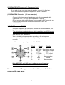
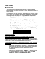
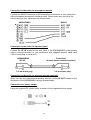
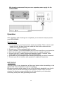
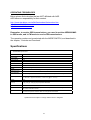
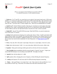
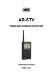
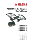
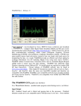
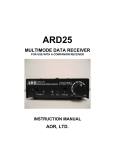
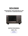
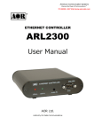
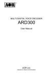
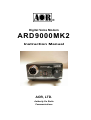
®
Digital Voice Modem
ARD9000MK2
Instruction Manual
AOR, LTD.
Authority On Radio
Communications
Thank you for purchasing the AOR ARD9000MK2 Digital Voice Modem.
All over the world, amateur radio operators have been discovering how
much fun it is to work HF without background noise.
AOR set the pace in this breakthrough technology with its ARD9800.
In response to worldwide demand, AOR had developed the ARD9000 which
makes digital voice communications even more affordable. Now, we have
developed the new ARD9000MK2.
AOR’s digital voice technology delivers audio quality you have to hear to
believe. Whether you are working digital voice across state lines of across
an ocean, amazing doesn’t seem strong enough to describe it.
With an ARD9000MK2, it’s easy to convert existing HF analog transceivers
to work digital voice with NO transceiver modifications. The ARD9000MK2
automatically detects a digital signal and decodes it, so you also maintain
full analog capabilities. Whether a contact comes in as digital or analog, the
ARD9000MK2 can handle it. Digital voice could be the biggest revolution in
HF radio since SSB!
Please read through this instruction manual and familiarize yourself with the
operation of the ARD9000MK2. We suggest you keep this instruction manual
for future reference.
We believe you will enjoy using the ARD9000MK2 as an enhancement to your
enjoyment of amateur radio.
AOR, LTD.
1
Features:
z No transceiver modifications needed.
The ARD9000MK2 uses the same audio frequencies (300Hz~2500Hz) as
microphone audio to modulate the voice signal. This allows you to use an analog
radio as a digital voice radio.
z Works on Single Side Band (SSB) mode.
The Automatic frequency clarifier function adjusts frequency drift automatically in
the SSB mode. (Approximately up to +/- 125Hz). Utilizes the OFDM (Multi Carrier
Modulation) circuit that is effective against Multi-path or Selective Fading.
z Automatic digital receive
Automatic voice signal detector recognizes the received signal as analog or digital,
quickly switching to the appropriate mode.
z Built-in high grade Vocoder (AMBE)
Utilizing high-grade digital voice compression delivers quality digital voice
communications.
z Built-in FEC error correction
A powerful error correction circuit delivers stable and reliable communications.
z Small and compact unit. Easy to operate.
Simply connect the ARD9000MK2 between the microphone jack and microphone.
No complicated modifications necessary. Optional interface cables for most
popular transceivers are available or you can build your own connectors.
z Wide range of operation voltages
Operates on 11 to 16V DC from an external power source.
z
Utilizes a uniquely designed high performance DSP engine.
z Uses established G4GUO open protocol.
The use of an open digital protocol means use of the ARD9000MK2 is permitted
on US Amateur Radio Bands (non-USA users should check applicable
regulations.)
ARD9000MK2 vs. ARD9800
You may already be familiar with our ARD9800 Multi-Mode and Digital Voice
Interface. The main difference between the ARD9000MK2 and the ARD9800 is
that the ARD9000MK2 is a VOICE ONLY modem. However, both models are fully
compatible for voice use.
Caution: Signal conditions vary greatly, as such; no warranty can be made on how the
ARD9000MK2 will perform in every circumstance.
2
Information to the Digital Device user required by the FCC
This equipment has been tested and found to comply with the limits for a Class B
digital device, pursuant to Part 15 of the FCC Rules. These limits are designed to
provide reasonable protection against harmful interference in a residential
installation.
This equipment generates, uses and can generate radio frequency energy and, if
not installed and used in accordance with the instructions, may cause harmful
interference to radio communications. If this equipment does cause harmful
interference to radio or television reception, which can be determined by turning
the equipment off and on, the user is encouraged to try to correct interference by
one or more of the following measures:
z
z
z
Reorient or relocate the receiving antenna.
Increase the separation between the equipment and receiver.
Connect the equipment to an outlet on a circuit different from that to which
the receiver is connected.
z Consult the dealer for technical assistance.
Precautions
To prevent fire, personal injury, or unit damage, please observe the following
precautions:
z
z
Do not attempt to adjust this unit unless instructed to do so by this manual.
Do not expose the unit to direct sunlight or place the unit close to heating
appliances.
z Do not place the unit in excessively dusty, humid or wet areas.
z AOR is not responsible for any damages to the radio equipment due to
improper settings or interface.
z AOR is not responsible for any loss of communications due to an unexpected
change in propagation or the operating environment.
3
Table of Contents
Page
Supplied & optional accessories ---------------------------------------------------------- 5
Magnetic mount ------------------------------------------------------------------------------- 5
Controls and functions ------------------------------------------------------------------------ 6
Front panel ------------------------------------------------------------------------------------ 6
Microphone connector ---------------------------------------------------------------------- 6
Overload indicator -------------------------------------------------------------------------- 6
Status LED ----------------------------------------------------------------------------------- 7
Mode switch ----------------------------------------------------------------------------------7
Synchronization switch -------------------------------------------------------------------- 8
Speaker volume adjustment with the switch ----------------------------------------- 8
Rear panel ------------------------------------------------------------------------------------ 8
DC IN connector --------------------------------------------------------------------------- 8
Speaker OUT connector ----------------------------------------------------------------- 9
Speaker IN connector -------------------------------------------------------------------- 9
Radio connector --------------------------------------------------------------------------- 9
Initial setting --------------------------------------------------------------------------------------10
Microphone level -------------------------------------------------------------------------- 10
Output level to radio ---------------------------------------------------------------------- 10
Input level from radio --------------------------------------------------------------------- 11
Installation ---------------------------------------------------------------------------------------- 12
Connection of the speaker-microphone -------------------------------------------------- 12
Connection to the radio (for microphone input) ----------------------------------------- 13
(for speaker input) ---------------------------------------------- 13
(for external speaker) ------------------------------------------ 13
Connection to a power supply --------------------------------------------------------------- 13
Operation ----------------------------------------------------------------------------------------- 14
Operating hints ----------------------------------------------------------------------------------- 14
Duty cycle
----------------------------------------------------------------------------------14
Operating frequencies --------------------------------------------------------------------- 15
Specifications -------------------------------------------------------------------------------- 15
Limited Warranty ------------------------------------------------------------------------------- 16
4
Supplied Accessories
The following items are provided in the package:
Accessory
Speaker Microphone
Speaker Cable
DC Power cable
8 pin metal plug (for radio output)
Instruction manual (this booklet)
Magnetic mount base (CR25) with screw (M3)
Quantity
1
1
1
1
1
1
Optional Accessories
A pre-wired microphone interface cable for most popular transceivers
D-6MY for YAESU® transceiver with 6 pin modular microphone connector
D-8MY for YAESU® transceiver with 8 pin modular microphone connector
D-8MI
for ICOM® transceiver with 8 pin modular microphone connector
D-8MK for KENWOOD® transceiver with 8 pin modular microphone connector
M-8MY for YAESU® transceiver with 8 pin metal microphone connector
M-8MI for ICOM® transceiver with 8 pin metal microphone connector
M-8MK for KENWOOD® transceiver with 8 pin metal microphone connector
Magnetic mount
The supplied magnetic mount base holds the ARD9000MK2 in place against a
metal surface. Simply screw it to the bottom panel’s center hole.
5
Controls and Functions
Front Panel
(1) Microphone Connector (SP/MIC)
Connect the supplied speaker-microphone to this connector. Speaker audio is
provided by the speaker-microphone.
If you wish to use your own microphone rather than the supplied speakermicrophone, you may rewire your microphone cable.
However, you will need to use your own external speaker connecting to the SP
OUT of the rear panel of the ARD9000MK2 as it does not have a built-in internal
speaker.
Below is a pin assignment of the speaker-microphone connector of the
ARD9000MK2.
Pin #
Signal
Details
1
2
3
4
5
6
7
8
Speaker output
Speaker output
BIAS
5V DC though 2.2 Kohm
GND
Chassis ground
NC
No connection
NC
No connection
MIC PTT
PTT (Push To Talk) input
MIC GND
Microphone ground
MIC IN
Microphone signal input
(2) Overload indicator (OVER)
1) Microphone level (in transmit mode)
Lit when the microphone input is overloaded.
A proper microphone input level will light the LED from time to time
6
when speaking into the microphone at a normal voice level. The
microphone level can be changed by adjusting the microphone level
controller.
Refer to the Presetting - Microphone Level chapter for details.
2) Input level (in receive mode)
To set the optimum level of audio from the transceiver (crucial for
good decoding of digital signals), this LED operates as an input level
indicator in receive mode, as follows:
LED flashing
LED off
LED always on
Input level too low
Input level optimal
Input level too high
(3) Status LED (STA)
SITUATION
Analog standby
Digital standby
Analog transmit
Digital transmit
Digital receive
LED color
Off
Green
Red
Orange
Green blinking
(4) Mode Switch (MODE)
There are 10 modes to choose from, as follows:
Position
Mode
Header
0
1
2
3
4
5
6
7
8
9
SSB
SSB
SSB
SSB
SSB
SSB
FM (*)
FM (*)
FM (*)
FM (*)
1.6 sec
1.4 sec.
1 sec.
1.6 sec.
1.4 sec.
1 sec.
1 sec.
1 sec
0.5 sec
0.5 sec
Analog/digital
switch
PTT->A
PTT->A
PTT->A
PTT->B
PTT->B
PTT->B
PTT->B
PTT->B
PTT->B
PTT->B
Voice squelch
All digital
Voice squelch
All digital
Remarks:
Header stands for the header tone length. The ARD9000MK2 synchronizes
on the header tones at the initial contact with other users.
PTT->A allows user to toggle between analog and digital transmission just by
quickly pushing the PTT button. The second press opens the microphone and
allows you to talk.
7
PTT->B Pushing the PTT button half way through toggles the analog/digital
mode, continue and fully press the PTT to open the microphone and talk.
Voice squelch: Allows you to hear both analog and digital transmissions.
All digital: The only audio you will hear is when the ARD9000MK2 detects
and decodes a digital transmission.
(*): In FM mode, the ARD9000MK2 operates best when your transceiver
squelch is fully open.
(5) Synchronization switch (SYNC)
Enables the re-synchronization of digital reception if synchronization is lost
during a communication session.
(6) Speaker volume adjustment with the switch (PWR/VOL)
Adjustment for speaker output level of the speaker-microphone, as well as
for the speaker output on the rear panel. Turning the knob fully
counterclockwise switches the unit off.
Rear Panel
(1) DC IN Connector (EIAJ Type 4)
Using the supplied DC power cable, connect to a regulated power
supply (11~16V DC).
We strongly recommend that you use a separate power supply for the
ARD9000MK2.
Color
RED
BLACK
Polarity
Positive (+)
Negative ( - )
8
(2) SPEAKER OUT Connector (3.5 mm mono jack)
If you wish to use your own external speaker, connect it to this jack.
Once connected, the speaker-microphone’s audio is disabled.
(3) SPEAKER IN Connector (3.5 mm mono jack)
Connect to the transceiver’s speaker output with the supplied cable.
(Input level: 0.5V – 5V p-p, input impedance: 8 Ohms)
Do not connect other audio sources like your radio’s ACC-connector or
LINE-OUT as those audio levels are insufficient to drive the
ARD9000MK2.
(4) RADIO Connector (RADIO)
Using the supplied 8-pin connector, connect the ARD9000MK2 to your
transceiver’s microphone input.
The optional pre-wired microphone cable is available from AOR for your
transceiver or you will need to prepare your own microphone connector
and cable for your transceiver.
Wire a shielded microphone cable according to the microphone
connector specifications of your radio (refer to your radio operator’s
manual).
Below are the pin assignments of the RADIO connector.
Pin #
1
2
3
4
5
6
7
8
Signal
Details
MIC GND Microphone ground
MIC OUT Microphone Output
PTT
PTT output
PTT GND
PTT ground
NC
No connection
NC
No connection
GND
Ground
NC
No connection
Note: MIC GND and GND must not be connected together
in the ARD9000MK2 connector or RF feedback will result.
It is recommended that you connect a station ground wire to a
screw on the rear panel.
9
Initial Setting
Microphone Level
The microphone level has been properly adjusted at the factory with the
provided speaker-microphone. Therefore, no further adjustment is needed for
normal operation.
If you wish to use your own microphone rather than the one included, you will
need to rewire your microphone cable to match the pins of the ARD9000MK2
and then adjust the microphone level as described in the following steps:
1. Connect your microphone to the Microphone connector on the
ARD9000MK2.
2. Make sure that the input level pot “MIC-IN” located on the bottom
side of the unit is set to factory default (9 o’clock position).
3. Press the PTT switch on your microphone and speak normally into
the microphone.
4. The OVERLOAD LED is lit either red for analog, or orange for digital
transmission (depending on your rotary switch position).
Adjust the “MIC-IN” pot on the bottom side of the ARD9000MK2 by
observing the OVERLOAD LED as follows:
LED off
LED sometimes lit
LED always on
Input level too low
Input level optimal
Input level too high
Output Level to Radio
Before readjusting the output levels to the transceiver, be sure that the
microphone level is correctly set first, as described above.
Although the factory setting should work with most transceivers, it is possible to
readjust the audio output level manually, as described below. This level must be
correctly set to enable effective operation with your transceiver.
The ARD9000MK2 allows you to apply separate settings for analog and digital
transmissions.
.
1. Connect the supplied speaker-microphone to the ARD9000MK2 first,
then connect your radio to the RADIO connector of the ARD9000MK2
by using your prepared connection cable. Now turn on the
ARD9000MK2.
2. Make sure that the output level pot “ANA-OUT” or “DIG-OUT” located
on the bottom side of the unit is set to factory default (4 o’clock
position for analog, 9 o’clock position for digital).
10
3. Press the PTT switch on the supplied speaker-microphone and speak
normally into the speaker-microphone.
In case the OVERLOAD LED is not lit, it means that the microphone’s
“MIC-IN” level has not been set properly. Refer to the
previous “Microphone level” section to correct this level first.
4. Adjust microphone gain control on the radio transceiver to suitable level.
It is recommended that you adjust the level so that the ALC function is
activated. If the ALC function activates too much, it might create audio
distortion and as a result, the communication link with the distant
station may be broken.
5. Adjust the output level pot on the bottom side of the ARD9000MK2
when the microphone gain control on the radio transceiver does not
adjust to provide a sufficient level.
Input Level from Radio
Although the factory setting should work with most transceivers (12 o’clock
position), it is possible to adjust the audio input level manually. This level
must be correctly set to enable effective operation with your transceiver.
If, and only if you are unable to achieve the correct level, then adjust the
input level pot “SP-IN” on the bottom of the ARD9000MK2:
Apply adjustments by observing the OVERLOAD LED as follows:
LED flashing
LED off
LED always on
Input level too low
Input level optimal
Input level too high
11
Installation
Connection of the speaker-microphone
Connect the supplied speaker-microphone to the SP/MIC connector of the
ARD9000MK2.
If you wish to use your own microphone or a speaker-microphone, please refer to
the wiring diagram shown below.
Pin #
1
2
3
4
5
6
7
8
Signal
Details
Speaker output
Speaker output
BIAS
5V DC though 2.2 Kohm
GND
Chassis ground
NC
No connection
NC
No connection
MIC PTT
PTT (Push To Talk) input
MIC GND
Microphone ground
MIC IN
Microphone signal input
12
Connection to the radio (for microphone output)
Connect the RADIO connector and the microphone connector of your transceiver
with the prepared microphone interface cable. Please make sure you have the
correct wiring to your transceiver as shown below.
ARD9000MK2
RADIO
Connection to the radio (for speaker input)
Connect the SP IN located on the rear panel of the ARD9000MK2 to the speaker
output (external speaker) of your transceiver with supplied speaker cable (with
3.5mm mono plug on each end).
ARD9000MK2
“SP IN”
Transceiver
Speaker output (external speaker)
3.5 mm mono plug
3.5 mm mono plug
Connection to the radio (for external speaker, optional)
When you use your own external speaker, connect it to the SP OUT located on the
rear panel of the ARD9000MK2 using a shielded cable.
Connection to a power supply
Using the supplied DC power cable, connect it to the regulated power supply.
13
We strongly recommend that you use a separate power supply for the
ARD9000MK2.
Operation
After installation and all settings are completed, you are almost ready to operate
your ARD9000MK2.
Operating hints
1. Try to coordinate your frequencies as closely as possible. There is some small
margin for error, but best results are obtained when both transceivers are
exactly on the same frequency.
2. Be sure your IF filters are about 3KHz or wider.
3. Don't "overdrive" your ARD9000MK2 with too much audio from your transceiver.
4. Don't transmit using "compression" (also known as a speech processor).
5. Be sure your ALC is within its specified operating region. If in doubt, lower
audio output seems to work better than a higher setting.
6. Be mindful of your bandwidth when selecting a frequency on which to transmit.
7. Be sure you will not interfere with operators on adjacent frequencies.
.
DUTY CYCLE
The duty cycle of your transceiver will be more intense when transmitting in the
digital mode. This is important to users of amplifiers.
Because the digital signal makes full use of the SSB audio bandwidth, you should
consider that you will be transmitting at the maximum power output you have
selected. At maximum power settings, this will likely result in your transmitter
consuming more power and generating more heat.
14
OPERATING FREQUENCIES
Below please find web sites that are NOT affiliated with AOR.
AOR takes no responsibility for their content.
http://www.standpipe.com/w2bri/fastmodem/fastmodem.htm
http://www.rfelectronics.com/
http://www.melwhitten.com/
Remember, to receive SSB transmissions, you need to set the ARD9000MK2
to SSB mode, and in FM mode to receive FM transmissions.
The operation modes can be selected with the MODE SWITCH, and described in
the chapter, “Controls and Functions”.
Specifications
ARD9000MK2 Specification
Modulation method:
OFDM
Bandwidth:
300 Hz - 2500 Hz, 36 carriers
Symbol Rate:
20 mS (50 baud)
Guard interval:
4mS
Tone steps:
62.5 Hz
Modulation method:
36 carriers: DQPSK (3.6K)
AFC:
+/- 125 Hz
Error correction:
Golay + Hamming
Header:
0.5-2sec. 3 tones + BPSK training pattern for synchronization
Digital voice chip:
AMBE2020 encoder, decoder
Signal detection:
Automatic Digital detect, Automatic switching between analogue mode and digital mode
Power requirements:
10 ~ 16 V DC, A p p r o x i m a t e l y 1 0 0 m A ( @ 1 2 V D C )
Weight:
350g.
Dimensions
(w, h, d):
70 (w) x 33 (h) x 98 (d) (mm) Projections excluded.
Connectors:
MIC/SP, Radio, DC-IN, SP-IN, SP-OUT.
Supplied access:
Speaker-microphone, DC cable, Speaker cable, 8-pin Radio connector, magnetic mount base
with screw, instruction manual.
Options:
Pre-wired microphone interface cable for most popular transceivers
Specifications are subject to change without notice or obligation.
15
LIMITED WARRANTY
AOR USA, Inc. (AOR) warrants its products as described below:
AOR will repair or exchange equipment as a result of defects in parts or
workmanship for a period of one year from the date of original retail purchase
from an authorized AOR dealer.
Exclusions
The following items are not covered by the AOR limited warranty:
1. Products that are damaged through accident, abuse, misuse, neglect, or user
modifications.
2. Problems that arise through failure to follow directions in the owner’s manual.
3. Exposure of the product to adverse or severe weather conditions, including
temperature extremes or water, including rainfall or immersion.
4. Exposure to toxic materials, biohazards, radioactive materials or other
contamination.
5. Repairs attempted by parties other than AOR or its authorized personnel.
6. Damage that results from improper installation, including improper voltage
and/or reversed polarity, or exposure of a receiver to signal levels exceeding
specifications.
7. Damage resulting through the use of accessories from manufacturers other
than AOR.
8. Equipment that has had serial numbers removed or altered in any way.
9. Damage that occurred as a result of shipment. Claims must be presented to
the carrier.
10. AOR is not responsible for any costs arising from installation or reinstallation of
the equipment, nor for any consequential (such as loss of use) damage claims.
Obtaining Warranty Service
1. You are responsible for shipping the product to AOR and any related costs.
2. Warranty claim must be accompanied by a legible copy of the original product
purchase receipt.
3. You must include a description of the problem(s) encountered with the product.
4. You must include your name, a valid ground shipping address (including zip
code) and telephone contact information.
5. AOR will ship the repaired (or replaced) product by ground transport.
16
Limitations
Any and all implied warranties, including those pertaining to merchantability and
utility for a specific purpose are limited to the duration of this limited warranty.
AOR’s limits on warranty pertain only to the repair or, at its option, replacement of
defective products. AOR shall not be liable for any other damages, including
consequential, incidental or otherwise, arising from any defect.
Some states do not allow limitations on how long an implied warranty lasts and
may not allow the exclusion of incidental or consequential damages. As such, the
above limitations may not apply in every case. This warranty gives you specific
legal rights and you may have other rights that apply in your state.
If you have questions about this limited warranty, or the operation of your AOR
product, contact AOR at (310) 787-8615 during normal business hours (9 am ~ 5
pm Pacific Time Zone), or write to AOR, 20655 S. Western Ave., Suite 112,
Torrance, CA 90501. You may also send a fax to AOR at (310) 787-8619.
Additional information is available at the AOR web site: www.aorusa.com
We suggest attaching your purchase receipt to this half of the warranty information
sheet and that you keep this information in a secure location.
AOR Model Number __________________________
Serial Number ________________________________
Dealer Name _________________________________
Purchase Date ________________________________
17
AOR, LTD.
2-6-4, Misuji, Taito-Ku
Tokyo, 111-0055, Japan
http://www.aorja.com
AOR USA, INC.
20655 S. Western Ave. Suite 112
Torrance, CA 90501-1800
Copyright © 2006
Phone: 310-787-8615
Fax: 310-787-8619
e-mail: [email protected]
URL: http://www.aorusa.com
All rights reserved
Copyright © 2006
18