1
NA
KS1
CZZ
ApollonII_general-copy_SEC.book
1 ページ 2004年9月6日 月曜日 午後4時57分
MODEL
AR-BC260
DIGITAL FULL COLOR MULTIFUNCTIONAL
SYSTEM
OPERATION MANUAL
(for general information and copier operation)
Page
• BEFORE USING
THE PRODUCT
• MANAGING THE MACHINE
• PERIPHERAL DEVICES
• BEFORE MAKING
COPIES
• BASIC PROCEDURE
FOR MAKING COPIES
• CONVENIENT COPY
FUNCTIONS
• MACHINE MAINTENANCE
(FOR COPYING)
• SPECIFICATIONS
1-1
2-1
3-1
4-1
5-1
6-1
7-1
8-1
Be sure to become thoroughly familiar with this manual to
gain the maximum benefit from the product.
Before installing this product, be sure to read the
installation requirements and cautions sections.
(Option) Duplex bypass / inverter unit and
Stand / 3 x 500 sheet paper drawer
Be sure to keep all operation manuals handy for reference
including this manual, the "Operation manual (for general
information and copier operation)" and operation manuals
for any optional equipment which has been installed.
ApollonII_general-copy_SEC.book
1 ページ 2004年9月6日 月曜日 午後4時57分
The power switch positions are marked " I " to indicate power "ON" and " " to indicate stand-by.
In the stand-by position, power is being supplied to a drying heater within the optical system of the copier.
Caution:
For complete electrical disconnection, pull out the main plug.
The socket-outlet shall be installed near the equipment and shall be easily accessible.
FOR YOUR RECORDS ...
To protect against loss or theft, record and retain for reference the machine’s serial number located on the back
of the unit.
Model Number
AR-BC260
Serial Number
Date of Purchase
Place of Purchase
Authorized Sharp Copier/Printer
Service Department Number
Warranty
While every effort has been made to make this document as accurate and helpful as possible, SHARP Corporation
makes no warranty of any kind with regard to its content. All information included herein is subject to change without
notice. SHARP is not responsible for any loss or damages, direct or indirect, arising from or related to the use of this
operation manual.
© Copyright SHARP Corporation 2004. All rights reserved. Reproduction, adaptation or translation without prior
written permission is prohibited, except as allowed under copyright laws.
This operation manual is also used for the AR-BC260 J.
ApollonII_general-copy_SEC.book
1 ページ 2004年9月6日 月曜日 午後4時57分
Part 1: General Information
ApollonII_general-copy_SEC.book
2 ページ 2004年9月6日 月曜日 午後4時57分
sec_apollon_00.fm 1 ページ
2004年11月16日 火曜日 午後1時15分
NOTES
● Considerable care has been taken in preparing this manual. If you have any comments or concerns about the
manual, please contact your nearest SHARP Service Department.
● This product has undergone strict quality control and inspection procedures. In the unlikely event that a defect
or other problem is discovered, please contact your dealer or nearest SHARP Service Department.
● Aside from instances provided for by law, SHARP is not responsible for failures occurring during use of the
product or its options, or failures due to incorrect operation of the product and its options, or other failures, or for
any damage that occurs due to use of the product.
The display screens, messages, and key names shown in the manual may differ from those on the actual machine
due to product improvements and modifications.
OPERATION MANUALS
The following operation manuals are provided for the machine. Please read the appropriate manuals as needed for
the features you wish to learn about.
● Operation manual (for general information and copier operation) (this manual):
The first half of this manual provides general information about the machine, including safety information, loading
paper, removing misfeeds, and regular maintenance.
The second half of the manual explains how to use the copy functions.
● Key operator's guide:
This primarily explains key operator programs for machine management and copier related functions. Key
operator programs for the printer, the facsimile and network scanner functions are explained in separate
manuals.
Key operator programs are used by key operators to configure function settings to meet the needs of the
customer.
● Operation manual (for facsimile):
This manual explains the procedures for using the machine as a facsimile. To use the fax function, the facsimile
expansion kit must be installed.
● Installation guide (for printer):
This explains how to connect the machine to your computer, install the printer driver for Windows, and configure
the printer driver settings.
● Operation manual (for printer)*:
This manual explains the procedures for using the machine as a printer.
● Operation manual (for network scanner)*:
This manual explains the procedures for using the machine as a network scanner when connected to a computer.
To use the network scanner function, a 256MB optional memory must be installed.
* The Operation manual (for printer) and the Operation manual (for network scanner) are provided as PDF files
on the supplied CD-ROM.
These manuals are not provided as printed manuals.
Some options may not be available in some countries and regions. This manual assumes that the optional
facsimile expansion kit has been installed, however, the basic operations of the machine are the same regardless
of the peripheral devices that are installed. For the peripheral devices that can be installed, see "Part names and
functions of peripheral devices" (1-6).
0-1
ApollonII_general-copy_SEC.book
2 ページ 2004年9月6日 月曜日 午後4時57分
INSTALLATION REQUIREMENTS
Improper installation may damage this product. Please note the following during initial installation and whenever the
machine is moved.
1. The machine should be installed near an accessible
power outlet for easy connection.
2. Be sure to connect the power cord only to a power
outlet that meets the specified voltage and current
requirements. Also make certain the outlet is
properly grounded.
● For the power supply requirements, see the
name plate on the main unit.
3. Do not install your machine in areas that are:
● damp, humid, or very dusty
● exposed to direct sunlight
● poorly ventilated
● subject to extreme temperature or humidity
changes, e.g., near an air conditioner or heater.
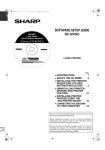
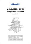
4. Be sure to allow the required space around the
machine for servicing and proper ventilation.
11-13/16"
(30cm)
23-5/8"
(60cm)
31-1/2"
(80cm)
23-5/8"
(60cm)
A small amount of ozone is produced within the copier during operation. The emission level is insufficient to cause
any health hazard.
NOTE:
The present recommended long term exposure limit for ozone is 0.1 ppm (0.2 mg/m3) calculated as an 8 hr. timeweighted average concentration.
However, since the small amount that is emitted may have an objectionable odor, it is advisable to place the copier
in a ventilated area.
0-2
ApollonII_general-copy_SEC.book
3 ページ 2004年9月6日 月曜日 午後4時57分
INSTALLATION REQUIREMENTS
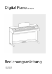
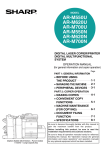
Moving this machine
Pull out the four handles as shown below, grasp them firmly, and keep the machine horizontal while moving it.
Left side
Exit
tray
Handles
Before lifting the machine,
fold up the exit tray and
tape it securely to the
machine.
Right side
Bypass
tray
Handles
Before lifting the machine,
fold up the bypass tray
and tape it securely to the
machine.
Caution
Two people are required to lift and carry this machine.
If the machine has been placed on a stand/paper drawer:
The stand/paper drawer is on casters for moving. Unlock the casters and the adjusters of the stand/paper drawer and
gently move the machine taking care to steady it to prevent it from toppling.
For locking and unlocking the casters and the adjusters, see page 0-4.
If the machine is to be left unused for a long time
If the machine is to be left unused for a month or longer, follow the procedure on pages 2-6 and 2-7 to release
the pressure on the fusing roller.
0-3
ApollonII_general-copy_SEC.book
4 ページ 2004年9月6日 月曜日 午後4時57分
CAUTIONS
1. Do not touch the photoconductive drum. Scratches
or smudges on the drum will cause dirty prints.
2. The fusing unit is extremely hot. Exercise care in
this area.
3. Do not look directly at the light source. Doing so may
damage your eyes.
Fusing unit
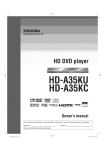
4. Four adjusters are provided on all optional stand/
paper drawer units. These adjusters should be
lowered until they contact the floor.
When moving the machine with the optional stand/
paper drawer, be sure to raise the adjusters. Also,
unlock the two casters at the front of the optional
stand/paper drawer. After moving the machine,
lower the four adjusters until they reach the floor and
lock the two casters.
5. Do not make any modifications to this machine.
Doing so may result in personal injury or damage to
the machine.
6. Since this machine is heavy, it is recommended that
it be moved by more than one person to prevent
injury.
Adjuster
Caster
Release
Lock
Lock
Release
7. When connecting this machine to a computer, be
sure to first turn both the computer and the machine
off.
8. Do not make copies of anything which is prohibited
from copying by law. The following items are
normally prohibited from printing by national law.
Other items may be prohibited by local law.
● Money ● Stamps ● Bonds ● Stocks
● Bank drafts ● Checks ● Passports
● Driver's licenses
"BATTERY DISPOSAL"
THIS PRODUCT CONTAINS A LITHIUM PRIMARY MEMORY BACK-UP BATTERY THAT MUST BE
DISPOSED OF PROPERLY. PLEASE CONTACT YOUR LOCAL SHARP DEALER OR AUTHORIZED SERVICE
REPRESENTATIVE FOR ASSISTANCE IN DISPOSING OF THIS BATTERY.
This product utilizes tin-lead solder, and a fluorescent lamp containing a small amount of mercury.
Disposal of these materials may be regulated due to environmental considerations.
For disposal or recycling information, please contact your local authorities or the Electronics Industries Alliance:
www.eia.org
0-4
ApollonII_general-copy_SEC.book
5 ページ 2004年9月6日 月曜日 午後4時57分
CONTENTS
OPERATION MANUALS.................................................0-1
INSTALLATION REQUIREMENTS.................................0-2
● Moving this machine..................................................0-3
CAUTIONS......................................................................0-4
CHAPTER 1
BEFORE USING THE PRODUCT
INTRODUCTION.............................................................1-2
MAIN FEATURES ...........................................................1-2
PART NAMES AND FUNCTIONS ..................................1-4
● Exterior ......................................................................1-4
● Interior .......................................................................1-5
● Part names and functions of peripheral devices........1-6
● Operation panel .........................................................1-8
● Touch panel...............................................................1-9
AUDITING MODE .........................................................1-11
● Using the machine when the auditing mode is
enabled ...................................................................1-11
CHAPTER 3
PERIPHERAL DEVICES
SADDLE STITCH FINISHER ......................................... 3-2
● Part names and functions ......................................... 3-2
● Specifications............................................................ 3-2
● Saddle stitch finisher functions ................................. 3-4
● Using the saddle stitch finisher ................................. 3-6
● Staple cartridge replacement and staple jam removal
.................................................................................. 3-7
● Misfeed in the saddle stitch finisher ........................ 3-10
● Troubleshooting saddle stitch finisher problems..... 3-12
● Stapling position quick reference guide for duplex
output ...................................................................... 3-13
● Relation between print image and saddle stitch ..... 3-14
LARGE CAPACITY TRAY............................................ 3-15
● Part name ............................................................... 3-15
● Specifications.......................................................... 3-15
● Loading paper in the large capacity tray ................. 3-16
● Misfeed in the large capacity tray ........................... 3-17
CHAPTER 2
MANAGING THE MACHINE
LOADING PAPER...........................................................2-2
● Loading paper in paper tray 1....................................2-2
● Changing the paper size in paper tray 1....................2-2
● Loading paper in the bypass tray ..............................2-4
● Loading paper in the stand/1 x 500 sheet paper drawer/
stand/3 x 500 sheet paper drawer................................2-7
● Specifications (stand/1 x 500 sheet paper drawer/
stand/3 x 500 sheet paper drawer)............................2-7
● Loading paper in the duplex module/2 x 500 sheet
paper drawer .............................................................2-8
● Specifications (duplex module/2 x 500 sheet paper
drawer) ......................................................................2-8
● Specifications of paper trays .....................................2-9
● Setting the paper type (except the bypass tray) ......2-11
● Setting the paper size when an extra size is loaded
.................................................................................2-11
● Setting the paper type and paper size in the bypass
tray...........................................................................2-12
CUSTOM SETTINGS....................................................2-13
● Operation procedure common to all custom settings
.................................................................................2-13
● About the settings....................................................2-14
REPLACING THE TONER CARTRIDGES ...................2-15
STORAGE OF SUPPLIES ............................................2-17
MISFEED REMOVAL....................................................2-18
● Misfeed removal guidance.......................................2-18
● Misfeed in the paper feed area................................2-19
● Misfeed in the transport area, fusing area, and exit
area .........................................................................2-20
● Misfeed in the stand/1 x 500 sheet paper drawer....2-21
● Misfeed in the stand/3 x 500 sheet paper drawer....2-21
● Misfeed in the duplex bypass/inverter unit and duplex
module/2 x 500 sheet paper drawer ........................2-22
TROUBLESHOOTING ..................................................2-24
0-5
ApollonII_general-copy_SEC.book
6 ページ 2004年9月6日 月曜日 午後4時57分
CONTENTS
CHAPTER 4
BEFORE MAKING COPIES
PART NAMES AND FUNCTIONS (The Reversing Single
Pass Feeder) .................................................................. 4-2
● Exterior ..................................................................... 4-2
● Operation Panel........................................................ 4-3
● Touch Panel (main screen of copy mode) ................ 4-4
REVERSING SINGLE PASS FEEDER .......................... 4-5
● Acceptable originals.................................................. 4-5
SETTING ORIGINALS ................................................... 4-6
SELECTING THE ORIGINAL SIZE................................ 4-8
IMAGE EDIT MENU ..................................................... 6-16
● Single color ............................................................. 6-17
● Mirror image ............................................................ 6-17
● Photo Repeat .......................................................... 6-18
● Multi shot................................................................. 6-19
● 11" x 17" (A3) Full-bleed ......................................... 6-21
● Multi-page enlargement .......................................... 6-22
● Pamphlet copy ........................................................ 6-24
JOB PROGRAM MEMORY .......................................... 6-25
● Storing a job program.............................................. 6-25
● Recalling a job program .......................................... 6-26
● Deleting a stored job program................................. 6-26
INTERRUPTING A COPY RUN ................................... 6-27
STORING, DELETING, AND USING ORIGINAL SIZES .... 4-9
CHAPTER 5
BASIC PROCEDURE FOR MAKING
COPIES
NORMAL COPYING....................................................... 5-2
● Copying from the reversing single pass feeder ........ 5-2
● Automatic two-sided copying from the reversing single
pass feeder ............................................................... 5-6
● Copying from the document glass ............................ 5-7
● Automatic two-sided copying from the document glass
.................................................................................. 5-9
EXPOSURE ADJUSTMENTS ...................................... 5-10
REDUCTION/ENLARGEMENT/ZOOM ........................ 5-12
● Automatic selection (auto image) ........................... 5-12
● Manual selection..................................................... 5-13
● XY ZOOM ............................................................... 5-15
SPECIAL PAPERS....................................................... 5-17
CHAPTER 6
CONVENIENT COPY FUNCTIONS
SPECIAL MODES .......................................................... 6-2
● Common operation procedure for using the special
functions ................................................................... 6-3
● Margin shift ............................................................... 6-4
● Erase ........................................................................ 6-5
● Dual page copy......................................................... 6-6
● Centering .................................................................. 6-7
● Transparency film with insert sheets ........................ 6-8
● Covers ...................................................................... 6-9
● B/W reverse ............................................................ 6-10
COLOR ADJUSTMENTS MENU.................................. 6-11
● RGB adjust ............................................................. 6-12
● Sharpness............................................................... 6-13
● Suppress background............................................. 6-13
● Color balance.......................................................... 6-14
● Brightness............................................................... 6-15
● Intensity .................................................................. 6-15
0-6
CHAPTER 7
MACHINE MAINTENANCE (FOR
COPYING)
REMOVING AN ORIGINAL MISFEED ........................... 7-2
● Removing a misfed original from the reversing single
pass feeder ............................................................... 7-2
USER MAINTENANCE (For copying) ............................ 7-3
CLEANING THE ORIGINAL SCANNING AREA ............ 7-3
TROUBLESHOOTING.................................................... 7-4
CHAPTER 8
SPECIFICATIONS
SPECIFICATIONS .......................................................... 8-2
● Copier and Main unit ................................................. 8-2
● Reversing single pass feeder.................................... 8-4
● Duplex bypass/inverter unit (optional)....................... 8-4
INDEX............................................................................. 8-5
ApollonII_general-copy_SEC.book
1 ページ 2004年9月6日 月曜日 午後4時57分
CHAPTER 1
BEFORE USING THE
PRODUCT
This chapter contains basic information that should be read before using
the product.
Page
INTRODUCTION ...........................................................................................1-2
MAIN FEATURES ..........................................................................................1-2
PART NAMES AND FUNCTIONS .................................................................1-4
● Exterior...................................................................................................1-4
● Interior ....................................................................................................1-5
● Part names and functions of peripheral devices ....................................1-6
● Operation panel......................................................................................1-8
● Touch panel ...........................................................................................1-9
AUDITING MODE ........................................................................................1-11
● Using the machine when the auditing mode is enabled.......................1-11
1-1
ApollonII_general-copy_SEC.book
2 ページ 2004年9月6日 月曜日 午後4時57分
INTRODUCTION
To gain the maximum benefits in using this product, it is recommended that the user read this manual to become
familiar with all the features and functions of the basic product and the precautionary information contained in the
manual.
This product is a high speed Digital full color copier/printer that can be expanded to become multifunctional through
the installation of optional peripheral devices. The product can be extended to include printer, network scanning or
network printing capabilities. This manual describes the basic use of the product as a copier and does not contain
information on using any of the optional peripheral devices. Separate operation manuals are included with each of
the optional peripheral devices. Refer to these manuals for their operation.
Original and paper sizes
This machine allows use of standard sizes in both the inch and AB systems.
These are shown in the tables below.
Sizes in the inch system
Sizes in the AB system
11" x 17" (LEDGER)
A3
8-1/2" x 14" (LEGAL)
B4
8-1/2" x 13" (FOOLSCAP)
A4
8-1/2" x 11" (LETTER)
B5
7-1/4" x 10-1/2" (EXECUTIVE)
A5
5-1/2" x 8-1/2" (INVOICE)
The meaning of "R" in original and paper size indications
Some original and paper sizes can be placed in either the portrait or landscape orientations. To differentiate between
landscape and portrait, the landscape orientation size indication will contain an "R". These are indicated as 8-1/2" x
11"R, 5-1/2" x 8-1/2"R, A4R, B5R, etc. Sizes that can be placed only in the landscape orientation (11" x 17", 8-1/2"
x 14", 8-1/2" x 13", A3, B4) do not contain the "R" in their size indication.
Size indication with "R"
Size indication without "R"
Landscape orientation
Portrait orientation
MAIN FEATURES
1 Full-color copies with vivid colors based on digital technology
Photos, color text, and other originals are scanned by full-color CCD sensors, and the acquired image
information is output in vivid full color at a resolution of 600 dpi using digital image processing technology.
The machine can also be used as a full color network printer and network scanner.
2 A range of optional units to enhance productivity
A range of optional equipment is available to enhance productivity, such as duplex units for producing two-sided
output, additional paper feed units to increase the number of available paper sizes and paper capacity, and
paper output units that are capable of stapling and saddle stitch binding.
1-2
sec_apollon_01_1.fm 3 ページ
2004年9月16日 木曜日 午後6時52分
MAIN FEATURES
3 Advanced image processing features based on digital technology
The scanned image data is converted to digital data, enabling the following advanced image processing features:
● Photo Repeat :
Up to 24 full-size copies of a photo image can be made on a single sheet of paper (page 6-18).
● Multi shot :
Up to four original pages can be copied onto a single sheet (page 6-19).
● Pamphlet copy* :
Copies of original pages are arranged in proper order for copying so that the copies can be center-stapled and
folded into a pamphlet (page 6-24).
* Pamphlet copy requires the Duplex module/2 x 500 sheet paper drawer and Duplex bypass/inverter unit
options. If a saddle stitch finisher is installed, copies can be stapled in two positions along the center of copies
and folded at the center.
4 Image processing manual exposure adjustment for optimal copying
Image processing is optimized for the type of original being copied (text, photo, mixed text and photo or map). This
along with the ability to manually adjust exposure makes it possible to obtain copies that are faithful to the original.
5 Standard offset function makes it easy to distinguish between sets of copies
As sets of copies are delivered to the center tray, each set is offset from the previous set for easy separation.
6 PostScript compatible
Installation of an optional PS expansion kit (AR-PK4) gives PostScript compatibility (PostScript 3).
As an ENERGY STAR® Partner, SHARP has determined that this product meets the
ENERGY STAR® guidelines for energy efficiency.
Energy saving features
This product has the following two power reducing modes to help conserve natural resources and reduce
environmental pollution.
Preheat mode
Preheat mode automatically reduces the temperature of the fusing unit after the time set in the key operator
programs elapses when the machine is on standby. This allows the machine to use less power while on
standby. The machine automatically returns to normal operation when a key is pressed on the operation
panel, or when an original is placed to make a copy or send a fax.
Auto power shut-off mode
Auto power shut-off mode automatically shuts off power to the fusing unit after the time set in the key
operator programs elapses when the machine is on standby. This minimizes the power used by the
machine while on standby. When this mode activates, the touch panel screen turns off.
To return the machine to normal operation, press the mode select key (the indicator of this key will be lit).
Auto power shut-off mode can be configured in the key operator programs. The mode is initially set (factory
default setting) to activate after 60 seconds elapses. (See page 9 of the key operator's guide.)
If a print job or fax is received while auto power shut-off mode or preheat mode is activated, the machine
automatically returns to normal operation.
The Environmental Choice Program guidelines are applied to the products only in Canada. The
products that meet the Environmental Choice Program guidelines carry the logo shown above.
The products without the logo may not meet the Environmental Choice Program guidelines.
1-3
1
ApollonII_general-copy_SEC.book
4 ページ 2004年9月6日 月曜日 午後4時57分
PART NAMES AND FUNCTIONS
Exterior
Left tray (See page 5-5)
Bypass tray
Finished sheets are deposited here.
Left side cover
Special papers (including transparency film) and
copy paper can be fed from the bypass tray.
Stand/1 x 500 sheet paper drawer *
Open this cover when a paper misfeed occurs in
the fusing unit or the transfer unit.
Reversing single pass feeder
(See page 2-7)
Stand/3 x 500 sheet paper drawer *
This automatically feeds originals to be scanned.
The feeder can turn the original over and scan the
back side as well as the front side for support of
two-sided originals.
Power switch
(See page 2-7)
Press to turn power on and off.
Front cover
Each tray can hold approximately 500 sheets of the
recommended paper for color (21 lbs. or 80 g/m2),
or approximately 500 sheets of SHARP standard
paper (21 lbs. or 80 g/m2).
Left side cover release
Open to replace toner cartridge.
Operation panel
Center tray (See page 5-5)
Finished sheets are deposited here.
Duplex module/2 x 500 sheet paper drawer*
(See page 2-8)
Paper tray
Push this release up to open the left side cover.
Duplex bypass/inverter unit and exit tray* (See
page 1-6)
*
,
1-4
,
and
are peripheral devices. For a description of these devices, see page 1-6.
ApollonII_general-copy_SEC.book
5 ページ 2004年9月6日 月曜日 午後4時57分
PART NAMES AND FUNCTIONS
Interior
1
Fusing unit
Toner cartridge
Toner images are fused here.
The toner cartridge must be replaced when
indicated on the operation panel. (See page 2-15)
Right side cover
CAUTION
The fusing unit is hot. Take care in removing misfed
paper.
Open when a misfeed has occurred in the paper
feed area.
Right cover of paper drawer
Open this cover to remove paper misfed in the
paper drawer.
1-5
ApollonII_general-copy_SEC.book
6 ページ 2004年9月6日 月曜日 午後4時57分
PART NAMES AND FUNCTIONS
Part names and functions of peripheral devices
Large Capacity tray (AR-LC8)
Stand/3 x 500 sheet paper drawer (AR-D18N)
The large capacity tray provides the added
convenience of having 3,500 sheets of 8-1/2" x 11"
or A4 paper (21 lbs. or 80 g/m2) available.
This stand has three paper trays. Each tray can
hold approximately 500 sheets of the
recommended paper for color (21 lbs. or 80 g/m2),
or approximately 500 sheets of SHARP standard
paper (21 lbs. or 80 g/m2).
Stand/1 x 500 sheet paper drawer (AR-D17N)
This stand has one paper tray. It can hold
approximately 500 sheets of the recommended
paper for color (21 lbs. or 80 g/m2), or
approximately 500 sheets of SHARP standard
paper (21 lbs. or 80 g/m2).
Duplex module/2 x 500 sheet paper drawer (AR-D19N)
This stand includes a module for automatic
two-sided printing and two paper trays. The two
trays can hold approximately 500 sheets of the
recommended paper for color (21 lbs. or 80 g/m2),
or approximately 500 sheets of SHARP standard
paper (21 lbs. or 80 g/m2). To perform two-sided
printing, a duplex bypass/inverter unit (AR-RB1) is
required.
1-6
Saddle stitch finisher (AR-F13)
The finisher can deliver sets saddle stitched and
folded at the paper centerline to form a pamphlet,
edge stapled in three different modes or unstapled.
For two-hole or three-hole output, a hole punch
module must be installed.
Exit tray (AR-TE3)
The exit tray is installed on the output outlet of the
machine or the duplex tray / inverter unit.
Duplex bypass/inverter unit (AR-RB1)
This module is required to automatically turn paper
over within the machine for automatic two-sided
printing.
ApollonII_general-copy_SEC.book
7 ページ 2004年9月6日 月曜日 午後4時57分
PART NAMES AND FUNCTIONS
■ Other optional equipment
● PS3 expansion kit (AR-PK4)
This kit provides compatibility of PostScript level 3
to the printer.
● Facsimile expansion kit (AR-FX10)
This kit must be installed to use the fax function.
● Fax memory (8 MB) (AR-MM9)
This adds memory for use by the fax function.
● 256 MB optional memory (AR-SM5)
This adds memory that is used for the copy
function, printer function, and scanner function.
■ Face-up and face-down output
After printing, the paper is delivered to the exit tray. This product has two exit trays (center tray and left tray). The
paper specifications (page 8-3) and output conditions differ for each tray; however, if the paper and output
conditions are such that the paper can be delivered to either tray, you can select the tray to which the paper will
go.
● Paper exits to the center tray face-down only.
● Paper exits to the left tray face-up only. However, if a duplex bypass/inverter unit has been installed,
face-down output is also possible. In this case, face-up or face-down output is automatically selected
according to the paper and output conditions (it is not possible to manually select face-up or face-down.)
1-7
1
ApollonII_general-copy_SEC.book
8 ページ 2004年9月6日 月曜日 午後4時57分
PART NAMES AND FUNCTIONS
Operation panel
Touch panel
Numeric keys
The machine status, messages and touch keys are
displayed on the panel. When using the touch
panel, first change the display to the mode that you
wish to use: printer mode, copy mode, network
scanner mode, or fax mode*. For details see the
next page.
Use to enter number values for various settings.
Mode select keys and indicators
This is used as a program key when using the copy
function, and to dial when using the fax function*.
Use to change modes and the corresponding
display on the touch panel.
[PRINT] key/READY indicator/DATA indicator
Press to enter the printer mode.
READY indicator
Print data can be received when this indicator is
lit.
DATA indicator
Lights up or blinks when print data is being
received. Also lights up or blinks when printing is
being performed.
[IMAGE SEND] key/LINE indicator/DATA
indicator
Press this key to switch the display between
network scanner mode and fax mode*. (See the
operation manuals for network scanner and fax.)
[COPY] key
Press to select the copy mode.
[ ] key ([ACC.#-C] key)
This is used when the copy, network scan, and fax*
functions are used.
[#/P] key
[C] key
This key is used in copy mode, network scanner
mode, and fax mode*.
[BLACK COPY START (
This is used to make black and white copies and to
scan a black and white original when the network
scan function is used. This is also used to scan an
original to be faxed using the fax function*.
[CA] key
This key is used in copy mode, network scanner
mode, and fax mode*.
[COLOR COPY START (
Use to adjust the contrast of the touch panel or to
set key operator programs. (See page 2-13.)
1-8
)] key
This is used to make full-color or single-color
copies and to scan a color original when the
network scanner function is used.
[JOB STATUS] key
Press to display the current job status. (See page
1-10.)
[CUSTOM SETTINGS] key
)] key
* When the fax option is installed.
ApollonII_general-copy_SEC.book
9 ページ 2004年9月6日 月曜日 午後4時57分
PART NAMES AND FUNCTIONS
Touch panel
Using the touch panel
Selection of function
[Example 1]
[Example 1]
JOB QUEUE
SETS / PRO
COPY
003 / 00
Suzuki
003 / 00
0666211221
010 / 00
Beep
tone
Items on the touch panel
are easily selectable by
touching
the
key
associated with the item
with a finger. Selection
of an item will be
accompanied with a
beep tone to confirm the
item was selected. Also,
the key area for the item
will be highlighted for
visual confirmation.
CANCEL
LEFT
BINDING
COMPLETE
Keys which are grayed
out on any screen are
not selectable. If a
grayed out key is
touched, a double beep
will be sounded.
The confirmation beeps can be disabled by a key
operator program. (See page 10 of the key
operator's guide.)
The touch panel screens shown in this manual are
printed images, and may appear different from the
actual screens.
RIGHT
BINDING
[Example 2]
When the machine is
used in the copy mode,
the functions shown in
the table below can only
be set or canceled on
the
special
feature
screen by alternate
touches of the function
keys on the panel.
DUAL PAGE
COPY
[Example 2]
1/13
Items
which
are
highlighted at the time a
screen
appears
are
already selected and will
be registered to function if
the [OK] key is touched.
OK
TRANSPARENCY
INSERTS
Copier feature
●
●
●
●
●
●
Dual page copy
Centering
Transparency inserts
Mirror image
11"x17" (A3) Full-bleed
B/W Reverse
[Example 3]
READY TO COPY.
OR
SPECIAL MODES
P
2-SIDED COPY
A4
OUTPUT
DUPLEX
A3
B4
When the machine is
used in the copy mode
and a special feature is
selected,
a
corresponding
icon
representing the feature
will appear on the touch
key and on the main
screen of the mode
selected. If this icon is
touched, the setting
screen of the function (or
a menu screen) will
appear, allowing the
settings to be checked
or adjusted and the
function to be canceled
easily.
1-9
1
ApollonII_general-copy_SEC.book
10 ページ 2004年9月6日 月曜日 午後4時57分
PART NAMES AND FUNCTIONS
Job status screen (common to print, copy, network scan and fax)
This screen is displayed when the [JOB STATUS] key on the operation panel is pressed.
A job list showing the current job at the top of the job queue or a list showing completed jobs can be displayed.
The contents of jobs can be viewed or jobs can be deleted from the queue. (The screen below is an example and
differs from actual screens.)
JOB QUEUE
SETS / PROGRESS
JOB QUEUE
STATUS
COPY
003 / 000
PAPER EMPTY*
Suzuki
003 / 000
WAITING
1/1
COMPLETE
DETAIL
066211221
001 / 000
WAITING
PRIORITY
STOP/DELETE
PRINT JOB
SCANNER JOB
Job list
This shows the current job and the jobs waiting to
be run. The icons to the left of the jobs in the queue
show the job mode.
Copy mode
Printer mode
Network scanner mode
Fax send job
Fax reception job
The displayed jobs in the job list are themselves
operation keys. To cancel printing or to give a job
the highest print priority, touch the relevant job key
to select the job and execute the desired operation
using the keys described in 5 and 6.
* "PAPER EMPTY" in the job status display
When a job status display indicates "PAPER
EMPTY", the specified paper size for the job is not
loaded in any of the trays.
When the [DETAIL] key appears, the key of a job in
the job queue can be touched followed by the
[DETAIL] key to change the paper size selection to
a different paper size (only in printer mode).
Mode select key
This only appears in the job status screen of fax
mode. The key is used to switch the job list display
between "JOB QUEUE" and "COMPLETE".
"JOB QUEUE": Shows stored jobs and the job in
progress.
"COMPLETE" : Shows finished jobs.
1-10
FAX JOB
[PRINT JOB] key
Use to display the print job list for printer, copy and
fax mode.
[SCANNER JOB] key
This displays a list of jobs that only used the
network scanner function.
[FAX JOB] key
This displays the transmission/reception status
and finished jobs of fax mode when the fax option
is installed.
Display switching keys
Use to switch the page of the displayed job list.
[STOP/DELETE] key
Use to cancel or delete the current job or delete the
selected reserved job. Note that a fax print job
cannot be canceled or deleted.
[PRIORITY] key
This only appears in the job status screen of fax
mode. Touch this key to give priority to a job that
has been selected in the job queue.
[DETAIL] key
The key is only effective for computer print jobs and
only appears in the job status screen of the printer
mode. It is used to display detailed information of a
selected print job and to change the paper size for
the print job.
sec_apollon_01_1.fm 11 ページ
2004年11月15日 月曜日 午前11時44分
AUDITING MODE
When the account counter function is turned on, a count is kept of the number of copy sheets used by each account
(maximum of 200 accounts). The counts can be displayed and totaled as needed.
The key operator programs can be used to enable auditing mode separately for copy mode, fax mode, network
scanner mode, and printer mode. (Page 6 of key operator's guide)
Using the machine when the auditing mode is enabled
The procedure for using the machine for copying functions when the Auditing Mode has been enabled for the copier
functions is explained below.
NOTES
● When the account counter is turned on for fax or network scanner functions, a message will appear prompting
you to enter your account number each time the touch panel is changed to the main screen of the function. Enter
your account number as explained below and then proceed with the job.
● When the account counter is turned on for the printer function, you must enter your account number in the setting
screen of the printer driver on your computer in order to print.
When the account counter is turned on, the following messages appear on the touch panel. There are two types of
prompts, depending on whether the account counter was turned on for both the color copy and the black and white
copy modes, or only for color copy mode.
●Account counter enabled for both the color copy and the black and white copy modes
ENTER YOUR ACCOUNT NUMBER.
●The account counter is enabled only for the color copy mode
ENTER YOUR ACCOUNT NUMBER FOR THE COLOR MODE.
PRESS [CANCEL] TO CHANGE TO B/W MODE.
CANCEL
AUDITING MODE FOR COLOR
When the [ ] key ([ACC.#-C] key) or the
[COLOR COPY START] key is pressed, the
message at left appears.
In this case, enter your 5-digit account number as explained on the next page to gain access to the copier functions.
1-11
1
ApollonII_general-copy_SEC.book
12 ページ 2004年9月6日 月曜日 午後4時57分
AUDITING MODE
your account number (5 digits) with
1 Enter
the numeric keys.
the appropriate steps to perform
2 Follow
the copy job.
As you enter your
account number, the
hyphens ( ) change to
asterisks ( ). If you
enter an incorrect digit,
press the
key and
re-enter the correct digit.
When a correct account
number is entered, the
following message will
appear.
When copying is begun, the following message
will appear.
ACCOUNT STATUS:COPIES MADE/REMAINING
B/W
S.COLOR
F.COLOR
This does not appear if the account counter
has only been set for color copy mode.
If a limit has been set by key operator program
for the number of copies that can be made by
the account, the remaining number that can be
made is displayed.
This message appears for several seconds and
then changes to the following message.
READY TO COPY.
NOTE
If "Account number security" is turned on in the key
operator programs, the following message will
appear in the event that an incorrect account number
is entered three times in a row. (Page 8 of the key
operator's guide)
PLEASE SEE YOUR KEY OPERATOR FOR
ASSISTANCE.
While this message appears (for about one minute),
no other operations can be performed.
1-12
READY TO COPY.
PRESS [ACC.#] WHEN FINISHED.
In the case of interrupt copying (page 6-27), the
following message will appear.
READY TO COPY. WHEN INTERRUPT COPYING
IS FINISHED PRESS [CANCEL].
the copy job is finished, press the
3 When
[ ] key ([ACC.#-C] key)
ApollonII_general-copy_SEC.book
1 ページ 2004年9月6日 月曜日 午後4時57分
CHAPTER 2
MANAGING THE MACHINE
This chapter explains how to load paper, replace the toner cartridge,
and remove paper misfeeds. It also contains information about supplies.
Page
LOADING PAPER..........................................................................................2-2
● Loading paper in paper tray 1 ................................................................2-2
●
Changing the paper size in paper tray 1 ................................................2-2
●
Loading paper in the bypass tray ...........................................................2-4
● Loading paper in the stand/1 x 500 sheet paper drawer/stand/3 x 500
sheet paper drawer..................................................................................... 2-7
●
Specifications (stand/1 x 500 sheet paper drawer/stand/3 x 500
sheet paper drawer) ...............................................................................2-7
●
Loading paper in the duplex module/2 x 500 sheet paper drawer .........2-8
●
Specifications (duplex module/2 x 500 sheet paper drawer) .................2-8
● Specifications of paper trays ..................................................................2-9
●
Setting the paper type (except the bypass tray)...................................2-11
●
Setting the paper size when an extra size is loaded ............................2-11
● Setting the paper type and paper size in the bypass tray ....................2-12
CUSTOM SETTINGS ..................................................................................2-13
●
Operation procedure common to all custom settings...........................2-13
● About the settings ................................................................................2-14
REPLACING THE TONER CARTRIDGES ..................................................2-15
STORAGE OF SUPPLIES ...........................................................................2-17
MISFEED REMOVAL ..................................................................................2-18
●
Misfeed removal guidance ...................................................................2-18
●
Misfeed in the paper feed area ............................................................2-19
● Misfeed in the transport area, fusing area, and exit area.....................2-20
●
Misfeed in the stand/1 x 500 sheet paper drawer ................................2-21
● Misfeed in the stand/3 x 500 sheet paper drawer ................................2-21
● Misfeed in the duplex bypass/inverter unit and duplex module/2 x 500
sheet paper drawer ..............................................................................2-22
TROUBLESHOOTING .................................................................................2-24
2-1
ApollonII_general-copy_SEC.book
2 ページ 2004年9月6日 月曜日 午後4時57分
LOADING PAPER
The message "ADD PAPER" or "OPEN TRAY AND ADD PAPER" will appear when paper runs out during operation.
Follow the procedure below to load paper.
NOTES
● Do not use curled or folded paper. Doing so may cause a misfeed.
● For best results use paper supplied by SHARP. (See pages 2-9, 2-17.)
● When you change the paper type and size in paper tray 1, you must change the paper type and size settings as
explained in "Setting the paper type" (page 2-11).
● Do not place heavy objects or press hard on any tray which is pulled out.
Loading paper in paper tray 1
1 Pull out paper tray 1.
3 Gently push tray 1 into the machine.
Gently pull the tray out
until it stops.
Push the tray firmly all the way into the machine.
the paper type.
4 Set
If you change the paper type, be sure to set the
paper type refer to "Setting the paper type" (page
2-11).
2 Load paper into the tray.
Load a stack of paper no
higher than the indicator
line (about 500 sheets of
the recommended paper for
color (21 lbs. or 80 g/m2), or
approximately 500 sheets
of SHARP standard paper
(21 lbs. or 80 g/m2)).
NOTE
If you load a different size of the same type of paper,
you only need to change the position of the size slide
(see step 2 below); you do not need to change the
paper type.
paper
5 Loading
complete.
in paper tray 1 is now
Changing the paper size in paper tray 1
The following paper size settings are available for paper tray 1: 11" x 17" to 8-1/2" x 5-1/2" (A3 to A5), and "EXTRA"*1.
Use the following procedure to change the size as needed.
*1 This is limited to square or rectangular paper, 11" x 17" to 8-1/2" x 5-1/2" (A3 to A5) size.
1 Pull out paper tray 1.
If paper remains in the tray, remove it.
the paper size slide to the paper
2 Adjust
size.
Move the paper size
slide right or left to
indicate the paper size
being loaded.
If a special size paper is
loaded in the paper tray,
set the size slide to
"EXTRA" to inform the machine that a special size
paper has been loaded. (When AB-based size
paper is loaded, move the size slide to "EXTRA".)
2-2
Note that setting the size slide to "EXTRA" only
informs the machine that a special size of paper
has been loaded; it does not inform the machine of
the specific size. If you wish to inform the machine
of the specific size, follow the steps in "Setting the
paper size when an extra size is loaded" (page 211). (If you do not set a size, part or all of the image
may not print.)
the guide plates A and B by
3 Adjust
squeezing their lock levers and sliding
them to the paper size to be loaded.
The guide plates A and
B are slidable. Adjust
them to the paper size to
be
loaded
while
squeezing their lock
levers.
ApollonII_general-copy_SEC.book
3 ページ 2004年9月6日 月曜日 午後4時57分
LOADING PAPER
4 Load paper into the tray.
the paper type of the paper that was
6 Set
loaded in the 1st tray.
If you loaded a different type of paper from the
previous paper, be sure to set the new paper type
as explained in "Setting the paper type" (page 211).
paper size in paper tray 1 is now
7 Changing
complete.
2
5 Gently push tray 1 into the machine.
Push the tray firmly all
the
way
into
the
machine.
NOTE
If the size slide position (step 2 of page 2-2) is not set correctly after changing the paper size, or if the paper type
(page 2-11) is not set correctly, incorrect paper selection or paper misfeeding may occur.
2-3
sec_apollon_02-1.fm 4 ページ
2004年9月14日 火曜日 午前10時44分
LOADING PAPER
Loading paper in the bypass tray
The bypass tray can be used to feed the same paper specified for paper tray 1 or for special papers. For paper types
that can be used in the bypass tray, see the specifications for the bypass tray in the paper tray specifications (page
2-9).
Up to 250 sheets of SHARP standard paper or up to 100 postcards can be set in the bypass tray.
NOTES
● After loading the paper in the bypass tray, be sure to set the paper type and size (step 4) if these were changed.
● Do not use inkjet paper. This may cause misfeeds in the fusing unit.
1 Open the bypass tray.
When loading paper that
will extend past the end
of the tray, pull out the
tray extension to support
the paper and to allow the
paper sensors to properly
sense the paper size.
Be sure to pull the tray extension all the way out. If
the tray extension is not pulled all the way out, the
size of the paper loaded in the bypass tray may not
display correctly.
To support papers that
extend past the tray
extension, pull out the
wire extension.
the copy paper all the way into the
3 Insert
bypass tray. (Do not force the paper in.)
Place the copy paper
face up. If the bypass
tray guides are set
wider than the copy
paper, the inside of the
machine may become
soiled, resulting in
smudges on succeeding copies. Special purpose
papers other than SHARP recommended
transparency film must be fed individually. Multiple
sheets of SHARP recommended transparency
film can be loaded in the bypass tray.
the type and size of the paper loaded in
4 Set
the bypass tray.
If you loaded a different type of paper from the
previous paper, be sure to set the new paper type
as explained in "Setting the paper type and paper
size in the bypass tray" (page 2-12). If you loaded
a special size of paper in the bypass tray, set the
paper size as explained in "Setting the paper type
and paper size in the bypass tray" (page 2-12).
(If you do not set a size, part or all of the image
may not print.)
completes the procedure for loading
5 This
paper in the bypass tray.
the bypass tray guides to the width of
2 Set
the copy paper.
NOTE
When loading paper in
the bypass tray or
closing the tray, close
the paper cover as
shown.
2-4
ApollonII_general-copy_SEC.book
5 ページ 2004年9月6日 月曜日 午後4時57分
LOADING PAPER
NOTES
● Be sure to load 5-1/2" x 8-1/2" paper, A6 paper, A5
paper, and postcards as shown in the diagram
below.
2
A6 paper, post cards.
5-1/2" x 8-1/2" paper, A5 paper.
● When loading plain paper other than paper
recommended for color, SHARP standard paper,
special media other than postcards, SHARPrecommended transparency film, or paper to be
printed on the back, the paper must be loaded one
sheet at a time. Loading more than one sheet at a
time will cause misfeeds.
● Before loading heavy paper, straighten any curling
in the paper.
● When adding paper, remove any paper remaining
in the tray, combine it with the paper to be added,
and reload as a single stack.
● Do not use paper that has already been printed on
by a plain paper fax machine or a laser printer.
This may cause printed images to become dirty.
● When printing on transparency film, be sure to
remove each sheet as it exits the machine.
Allowing sheets to stack in the output tray may
cause curling.
● Use only SHARP-recommended transparency
film. Insert the film so that the rounded corner is on
the left for horizontal loading, or on the right for
vertical loading.
Horizontal Vertical
loading
loading
● When loading multiple sheets of transparency film
in the bypass tray, fan the sheets several times
before loading.
2-5
sec_apollon_02-1.fm 6 ページ
2004年9月14日 火曜日 午前10時45分
LOADING PAPER
■ Setting envelopes or postcards
When setting envelopes or postcards in the bypass tray, set them in the orientation shown below.
Loading postcards
Insert the postcard with the side to be printed on
facing up. The postcard should be oriented as
shown in the diagram.
Loading envelopes
Only the front side of envelopes can be printed.
Insert the envelope with the front side facing up.
Printing onto envelopes or postcards
●Attempting to print onto both sides of envelopes or postcards may result in misfeeds or poor prints.
●Do not use pre-printed envelopes.
●Before inserting a postcard or envelope, straighten any curled edges. Curled edges may cause creases, color
deviations, misfeeds, and poor quality images.
Printing onto envelopes
●Attempting to print on envelopes that have metal clasps, plastic snaps, string closures, windows, linings, selfadhesive patches or synthetic materials may cause misfeeds, inadequate toner adherence or other trouble.
●Envelopes with embossed surfaces may cause the prints to become smudged.
●Use only envelopes which are flat and crisply folded. Curled or poorly formed envelopes may be poorly printed
or may cause misfeeds.
●Print quality is not guaranteed in the area 13/32" or 10 mm from the
edges of the envelope.
●Print quality is not guaranteed on parts of envelopes where there is a
large step-like change of thickness, such as on three-layer or four-layer
envelopes.
Can be used
●Print quality is not guaranteed on envelopes having peel off flaps for
sealing the envelopes.
Cannot be used
Fusing unit pressure adjusting levers
In some cases damage to the envelopes, color deviations, or smudging may occur even if envelopes within the
specifications are used. This problem may be reduced by shifting the fusing unit pressure adjusting levers from
their normal pressure position to the lower pressure position. Follow the procedure on the next page. (2-7)
NOTE
Be sure to return the lever to the normal position when you have finished feeding envelopes. If not, inadequate
toner adherence, paper misfeeds or other trouble may occur.
2-6
ApollonII_general-copy_SEC.book
7 ページ 2004年9月6日 月曜日 午後4時57分
LOADING PAPER
the duplex bypass/inverter unit
1 Unlatch
and slide it to the left.
close the duplex bypass/inverter
3 Gently
unit.
Unlatch the unit and
gently move it away from
the machine. If the
machine is not equipped
with a duplex bypass/
inverter unit, open the
side cover similarly.
If the machine is not
equipped with a duplex
bypass/inverter
unit,
close the side cover.
the two fusing unit pressure
2 Lower
adjusting levers marked A and B in the
2
illustration.
A
B
Normal
position
Lower pressure
B:Front side of
position
fusing unit
A:Rear side of
fusing unit
Loading paper in the stand/1 x 500 sheet paper drawer/
stand/3 x 500 sheet paper drawer
Upper tray / middle tray / lower tray*
Up to 500 sheets of paper recommended for color or SHARP recommended plain paper can be loaded in these trays.
The method of loading paper is the same as for paper tray 1 in the main unit (see the explanation on page 2-2).
* The stand/1 x 500 sheet paper drawer only has the upper tray.
NOTE
If the size of paper being loaded is different from the previous size, or is an extra size, or if the paper type is different
from the previous type, you must change the paper tray settings in the custom settings. Change the settings as
explained in "Setting the paper type" and "Setting the paper size when an extra size is loaded" on page 2-11.
Specifications (stand/1 x 500 sheet paper drawer/stand/3 x
500 sheet paper drawer)
Name
Paper size/weight
Paper capacity
Power supply
Dimensions
Weight
Stand/1 x 500 sheet paper drawer (AR-D17N) Stand/3 x 500 sheet paper drawer (AR-D18N)
11" x 17", 8-1/2" x 14", 8-1/2" x 13", 8-1/2" x 11", 8-1/2" x 11"R,
7-1/4" x 10-1/2"R, 5-1/2" x 8-1/2", Extra. (A3, B4, A4, A4R, B5, B5R, A5)
/ 17 to 28 lbs. or 64 to 105 g/m2
Paper recommended for color (21 lbs. or 80 g/m2): 500 sheets;
SHARP standard paper (21 lbs. or 80 g/m2): 500 sheets
Supplied from the main unit
23-5/8" (W) x 25-9/32" (D) x 15-7/8" (H) (600 mm (W) x 642 mm (D) x 403 mm (H))
(not including the adjuster)
Approximately 49.6 lbs. or 22.5 kg
Approximately 65.0 lbs. or 29.5 kg
Specifications are subject to change for improvement without notice.
2-7
ApollonII_general-copy_SEC.book
8 ページ 2004年9月6日 月曜日 午後4時57分
LOADING PAPER
Loading paper in the duplex module/2 x 500 sheet paper
drawer
Upper tray:
The upper tray contains a duplex module that automatically turns print paper over for automatic two-sided printing.
Middle and lower paper trays:
The middle and lower trays are paper trays.
Up to 500 sheets of paper recommended for color or SHARP recommended plain paper can be loaded in these trays.
The method of loading paper is the same as for paper tray 1 in the main unit. See the explanation on page 2-2.
NOTE
If the size of paper being loaded is different from the previous size, or is an extra size, or if the paper type is different
from the previous type, you must change the paper tray settings in the custom settings. Change the settings as
explained in "Setting the paper type" and "Setting the paper size when an extra size is loaded" on page 2-11.
Specifications (duplex module/2 x 500 sheet paper drawer)
Name
Duplex module/2 x 500 sheet paper drawer (AR-D19N)
Paper size/weight
11" x 17", 8-1/2" x 14", 8-1/2" x 13", 8-1/2" x 11", 8-1/2" x 11"R, 7-1/4" x 10-1/2"R,
5-1/2" x 8-1/2", Extra. (A3, B4, A4, A4R, B5, B5R, A5)
/ 17 to 28 lbs. or 64 to 105 g/m2
Paper capacity
Paper recommended for color (21 lbs. or 80 g/m2): 500 sheets;
SHARP standard paper (21 lbs. or 80 g/m2): 500 sheets
Power supply
Supplied from the main unit
Dimensions
23-5/8" (W) x 25-9/32" (D) x 15-7/8" (H) (600 mm (W) x 642 mm (D) x 403 mm (H))
(not including the adjuster)
Weight
Approximately 68.3 lbs. or 31 kg
Duplex module
Size of plain paper
11" x 17", 8-1/2" x 14", 8-1/2" x 13", 8-1/2" x 11", 8-1/2" x 11"R, 7-1/4" x 10-1/2R",
5-1/2" x 8-1/2", A3, B4, A4, A4R, B5, B5R, A5
Weight of plain paper
17 to 54 lbs. or 64 to 200 g/m2
Number of sheets
One sheet (single pass type)
Specifications are subject to change for improvement without notice.
2-8
ApollonII_general-copy_SEC.book
9 ページ 2004年9月6日 月曜日 午後4時57分
LOADING PAPER
Specifications of paper trays
The specifications for the types and sizes of paper that can be loaded in the paper trays are shown below.
Paper tray type
A
Paper tray 1
Tray No.
(tray
name)
Applicable paper types
Applicable paper sizes
Remarks
Paper recommended for color
11"x17", 8-1/2"x14",
8-1/2"x13", 8-1/2"x11",
8-1/2"x11"R, 5-1/2"x8-1/2",
7-1/4"x10-1/2"R, Extra.
(A3, B4, A4, A4R, B5, B5R,
A5)
See
"STORAGE
OF
SUPPLIES"
on page 2-17
Plain paper
11"x17", 8-1/2"x14",
8-1/2"x13", 8-1/2"x11",
8-1/2"x11"R, 5-1/2"x8-1/2",
7-1/4"x10-1/2"R, Extra.
(A3, B4, A4, A4R, B5, B5R,
A5)
See
"More
information on
plain paper"
on the next
page
Tray 1
Same as paper types and sizes in row A
* Paper size 12" x 18" (A3W) and A6R can also be used in the bypass tray
Heavy
paper 1
B
Bypass tray
Bypass
tray
Special
Heavy
paper (Refer paper
to the next
Heavy
page
for
paper 2
applicable
special
Transparency film
papers.)
Envelopes
C
Stand/1 x 500
sheet paper drawer
D
Stand/3 x Upper
500 sheet Middle
paper
Lower
drawer
E
Duplex
Upper
module/2 x
500 sheet Middle
paper
Lower
drawer
F Large Capacity tray
5-1/2"x8-1/2" - 12"x18" (A6R
- A3W), Special (paper
weight: 28 to 54 lbs. (106 to
200 g/m2)), Postcard
5-1/2"x8-1/2" - 12"x18" (A6R
- A3W), Special (paper
weight: 54 to 80 lbs. (201 to
300 g/m2))
Transparency film
See
"More
information on
special media
that can be
used" on the
next page
●Standard-size envelopes
that can be used
:COM10,Monarch,DL,C5
Tray 2
Tray 2
Same as paper types and sizes in row A
Tray 3
Tray 4
Duplex
Duplex module
(See page 2-8 for paper sizes and weights that can be used.)
Tray 2
Tray 3
Same as paper types and sizes in row A
Tray 4*1
or
Same as paper types in row A
Tray 5*2
8-1/2"x11" (A4)
See
the
specifications
in
"LARGE
CAPACITY
TRAY"
on
page 3-15, and
"More
information on
plain paper" on
the next page.
*1 When the Duplex module/2 x 500 sheet paper drawer is installed.
*2 When the Stand/3 x 500 sheet paper drawer is installed.
2-9
2
ApollonII_general-copy_SEC.book
10 ページ 2004年9月6日 月曜日 午後4時57分
LOADING PAPER
■ More information on plain paper
The following restrictions apply to plain paper. Be sure to load the paper correctly. Incorrect loading may result
in skewed feeding or misfeeds.
Plain
paper
SHARP
paper
standard
Restrictions on paper
other than SHARP
standard paper
Paper in inch system
Paper in AB system
5-1/2" x 8-1/2" - 12" x 18"*
A6R - A3W*
21 lbs.
80g/m2
17 to 28 lbs. or 64 to 105g/m2
Recycled, colored, pre-punched, pre-printed and letterhead papers must conform to the same conditions as
above.
* In the large capacity tray, only 8-1/2" x 11" size paper can be used when using inch sizes, and only A4 can be
used when using AB sizes.
■ More information on special media that can be used
The following restrictions apply to special media. The use of incorrect media may result in fusing problems (weak
adhesion of toner to paper or toner smudging when rubbed), skewed feeding, misfeeds, or other failures.
Type
Heavy
paper
Special
paper
Remarks
heavy paper 1
For paper sizes from 5-1/2" x 8-1/2" to 12" x 18" (A6R to A3W),
paper weights from 28 to 54 lbs. (106 to 200 g/m2) can be used.
● Postcards can be used.
Do not use folded postcards, picture postcards, or postcards with
a coated front. These may cause misfeeds or a dirty printed
image.
heavy paper 2
For paper sizes from 5-1/2" x 8-1/2" to 12" x 18" (A6R to A3W),
paper weights from 54 to 80 lbs. (201 to 300 g/m2) can be used.
Transparency film
Use SHARP recommended transparencies.
Envelopes
Applicable standard envelopes: COM-10, Monarch, DL, C5
Envelopes can only be fed from the Bypass tray. Applicable paper
stock weight for envelopes is 20 to 23 lbs. or 75 to 90 g/m2
● Special paper such as heavy paper 2, transparency film, and envelopes cannot be output to the center tray.
● Paper that cannot be output to the center tray is output face-up to the left tray.
■ Paper that can be used for automatic two-sided printing
Paper used for automatic two-sided printing (paper that can be fed through the duplex module) must meet the
following conditions:
Paper type
Paper size
: Plain paper as specified on page above.
: Must be one of the following standard sizes: 11" x 17", 8-1/2" x 14", 8-1/2" x 13", 8-1/2" x 11",
8-1/2" x 11"R, 7-1/4" x 10-1/2" or 5-1/2" x 8-1/2" (A3, B4, A4, A4R, B5, B5R or A5)
Paper weight : 17 to 54 lbs. or 64 to 200 g/m2
NOTES
● Special papers as described above cannot be used for automatic two-sided printing. Heavy paper up to 54 lbs.
(200 g/m2) can be used.
● The image quality and toner fusibility of special papers may change due to ambient conditions, operating
conditions, and paper characteristics, resulting in image quality inferior to that of SHARP standard paper.
● Various types of plain paper and special paper are sold. Some of these cannot be used in the machine. Please
consult your retailer or your dealer when buying paper.
2-10
ApollonII_general-copy_SEC.book
11 ページ 2004年9月6日 月曜日 午後4時57分
LOADING PAPER
Setting the paper type
(except the bypass tray)
Setting the paper size when
an extra size is loaded
Follow these steps to change the paper type setting
when the paper type has been changed in a paper tray.
For the paper types that can be used in each tray, see
page 2-9. To change the paper type setting for the
bypass tray, see page 2-12.
When a paper tray is set to "extra", this informs the
machine that an extra size is being used. It does not
inform the specific size. To enter the specific size of the
paper loaded, follow the steps below.
For example, if A4 size paper is loaded in the tray (with
the size slide set to "extra"), you can use this procedure
to set the paper size recognized by the machine to A4
size. If you loaded an irregular size of paper, you can
enter the dimensions of the paper.
To set the paper size when an extra size of paper is
loaded in the bypass tray, see page 2-12.
1 Press the [CUSTOM SETTINGS] key.
The custom setting
menu
screen
will
appear.
steps 1 through 4 of "Setting the
1 Perform
paper type" at left.
2 Touch the [TRAY SETTINGS] key.
TOT L COUNT
CONTRA
The paper tray selection
screen will appear.
ADDRES
CONTRO
TRAY SETTINGS
KEYBOARD
SELECT
the tray specifications on page 2-9.)
PLAIN /
TRAY 2
PLAIN /
OK
EXTRA SIZE
the paper tray for which the setting
3 Select
is to be made. (For the tray numbers, see
TRAY 1
CUSTOM SETTINGS
TRAY 3 TYPE/SIZE SETTING
KEY
TYPE / SIZE
the
key to display the paper size
2 Touch
setting screen.
If the desired tray is not
on the display, use
or
key to scroll the
display until it appears.
A3
B4
A4
B5R
A5
8K
16K
16KR
11X17
81/2 X14
81/2 X13
81/2 X11
81/2X11R
51/2 X81/2
71/4X101/2R
EXTRA
A4R
B5
2/3
the loaded paper size appears in the
3 When
display (if you loaded an AB-based size
such as A4), touch the size key to highlight
it, and then touch the [OK] key to complete
the procedure.
an irregular size of paper was loaded
4 Ifafter
the [EXTRA] key was touched, touch
the
key in the screen of step 2 to display
the following screen.
the type of paper that was loaded in
4 Select
the tray.
PLAIN
LETTER HEAD
PRE-PRINTED
PRE-PUNCHED
RECYCLED
COLOR
The currently selected
paper type will be
highlighted. To change
the setting, touch the
desired type.
NOTE
Special paper such as transparency film,
envelopes, and postcards can only be used in the
bypass tray.
the
5 Touch
setting.
X
5
1/
2
(5 1/2 17)
inch
Y
7
1/
4
(7 1/4 11 3/4)
inch
When the screen opens the X key will be
highlighted. Use the
and
touch keys to
enter the X dimension. Next touch the Y key to
highlight it and enter the dimensions for Y.
The permitted range for the X dimension is 5-1/2 to
17 inches (139 to 432 mm), and the permitted
range for the Y dimension is 7-1/4 to 11-3/4 inches
(182 to 297 mm).
When both have been entered, touch the [OK] to
complete the operation.
[OK] key to complete the
2-11
2
ApollonII_general-copy_SEC.book
12 ページ 2004年9月6日 月曜日 午後4時57分
LOADING PAPER
Setting the paper type and paper size in the bypass tray
Follow the steps below to set the type and size of the paper loaded in the bypass tray.
1 Touch the [PAPER SELECT] key.
(When copy mode is selected)
Touch the [PAPER
SELECT] key in the
AUTO
8½x11
main screen of the copy
PAPER SELECT
mode.
[HEAVY PAPER 1]
3 Touch
PAPER 2], and go to step 6.
HEAVY PAPER1 28+lbs.
54 lbs.
HEAVY PAPER2 54+lbs.
80 lbs.
For the types of heavy paper that can be used, see
page 2-10.
100%
(When printer mode is selected)
Touch the [PAPER
SELECT] key in the
8½x11
main screen of printer
PAPER SELECT
mode.
CONDITION
SETTINGS
2 Touch the key for the desired paper type.
[SPEED MODE] or [QUALITY MODE]
4 Touch
for the transparency film, and go to step 7.
SPEED MODE
QUALITY MODE
● SPEED MODE is for fast printing.
● QUALITY MODE is for a high quality image.
5 Touch the type of envelope, and go to step 7.
ENVELOPE
100%
COPY RATIO
(When printer mode is selected)
PLAIN
HEAVY PAPER
PAPER SELECT
TRANSPARENCY
CONDITION
SETTINGS
ENVELOPE
OK
COM-10
(When copy mode is selected)
UTO
The key for the selected
EXPOSURE
PLAIN
paper type will be
HEAVY PAPER
highlighted.
PAPER SELECT
TRANSPARENCY
or [HEAVY
MONARCH
C5
DL
inserted a non-standard size of paper
6 Ifinyou
the bypass tray, remove the checkmark
from "ENABLE AUTO SIZE DETECTION" and
then touch the [EXTRA SIZE] tab. When the
screen opens, the X key will be highlighted.
Use the
and
touch keys to enter the X
dimension. If you inserted a standard size of
paper in the bypass tray, make sure that a
checkmark appears in the [ENABLE AUTO
SIZE DETECTION] checkbox.
ENABLE AUTO SIZE DETECTION
The steps that follow differ depending on the
paper type selected. Follow the steps for the
selected type.
● If you touched [PLAIN], go to step 6.
● If you touched [HEAVY PAPER], go to step 3
● If you touched [TRANSPARENCY], go to step 4.
● If you touched [ENVELOPE], go to step 5.
2-12
EXTRA SIZE
OK
X
5 ½
(5 1/2 17)
inch
Y
4
(4 11 3/4)
inch
BASIC SETTING
Next touch the
key to
highlight it and enter the
dimensions for Y.
The permitted range for
the X dimension is 5-1/2
BASIC SETTING
EXTRA SIZE
to 17 inches (139 to 432
mm), and the permitted
range for the Y dimension is 4 to 11-3/4 inches
(100 to 297 mm).
7 Touch the [OK] key to complete the setting.
sec_apollon_02-1.fm 13 ページ
2004年9月14日 火曜日 午前10時47分
CUSTOM SETTINGS
The items that can be set with the custom settings are shown below.
● Total count ................................... The number of pages processed by the machine and optional equipment
can be displayed. (See page 2-14.)
● Display contrast ........................... Used to adjust the contrast of the operation panel display. (See page 2-14.)
● List print ....................................... Used to print a list of machine settings. (See page 2-14.)
● Clock adjust .................................... Used to set the date and time of the built-in clock of the machine. (See this page.)
● Tray settings ................................ The paper type, paper size and automatic tray switching can be set for each
tray. Automatic tray switching allows feeding to switch between trays
loaded with the same type and size of paper. If one tray runs out of paper
during printing, printing will continue from the other tray. (See page 2-14)
For the detailed descriptions and use of the settings listed below, see the Operation manuals
for fax* and network scanner.
● Address control............................ Use this to store fax destinations (fax numbers). This is also used to store
groups, memory boxes, and user indexes.
E-mail addresses, user indexes, and scanner senders can be stored for the
network scanner function.
● Receive mode.............................. Use this to configure fax reception settings (auto/manual).
● Fax data forward.......................... Faxes received to memory can be forwarded to another destination.
● Keyboard select........................... When using the fax function or network scanner function, you can switch
the arrangement of the letter keys in the display keyboard used for storing
and editing destinations in the English character entry screen.
● Key operator program.................. These are programs that are used by the key operator (administrator of the
machine) to configure machine settings. A key appears for these settings in
the custom settings menu screen. For information on these settings, see
the key operator's guide.
* These fax settings can be configured only if the fax function has been enabled.
Operation procedure common to all custom settings
1 Press the [CUSTOM SETTINGS] key.
The custom setting
menu
screen
will
appear.
the key of the desired
2 Touch
display its setting screen.
The settings accessed by touching the [CLOCK]
key are explained here.
CUSTOM SETTINGS
More information on setting procedures
In the following type of screen, a setting is turned
on when a checkmark ( ) appears next to the
key. A checkmark will appear or disappear by
alternate touches of the checkmark box. In the
following screen, tray 1 can be used in print, copy,
and fax modes. Tray 2 can only be used in the
copy mode.
EXIT
TOTAL COUNT
DISPLAY
CONTRAST
LIST PRINT
CLOCK
TRAY SETTINGS
ADDRESS
CONTROL
RECEIVE MODE
FAX DATA
FORWARD
KEYBOARD
SELECT
KEY OPERATOR PROGRAMS
Detailed descriptions for program settings start on
the next page.
The procedure for setting the clock is shown below
as an example.
CUSTOM SETTINGS
CLOCK ADJUST
CUSTOM SETTINGS
item to
OK
YEAR
MONTH
DAY
HOUR
MINUTE
2004
11
01
00
00
OK
TRAY SETTINGS
TYPE / SIZE
PRINT
COPY
FAX
1/2
TRAY 1
PLAIN /
TRAY 2
PLAIN /
DATE FORMAT
DAYLIGHT SAVING TIME SETTING
2-13
2
ApollonII_general-copy_SEC.book
14 ページ 2004年9月6日 月曜日 午後4時57分
CUSTOM SETTINGS
the year, month, day, hour or
3 Touch
minute key, and then use the
or
key
to adjust the setting.
● If you select a non-existent date (for example, Feb.
30), the [OK] key will gray out to prevent entry of the
date.
● Select [DAYLIGHT SAVING TIME SETTING]
checkbox to have the time automatically change at
the beginning and end of daylight saving time.
4 Touch the [OK] key.
finish the setting operation, touch the
5 To
[EXIT] key.
CUSTOM SETTINGS
EXIT
TOTAL COUNT
DISPLAY
CONTRAST
LIST PRINT
CLOCK
TRAY SETTINGS
ADDRESS
CONTROL
RECEIVE MODE
FAX DATA
FORWARD
KEYBOARD
SELECT
KEY OPERATOR PROGRAMS
About the settings
■ Total count
This displays the following sheet counts:
The number of sheets printed in copy, print, and
fax modes.
The number of sheets transmitted using the fax
function and scanned using the network scanner
function.
The number of sheets used by optional
equipment such as the reversing single pass
feeder and the duplex module of the duplex
module/2 x 500 sheet paper drawer, and the
number of sheets stapled by the saddle stitch
finisher.
In the case of
only,
● Each sheet of paper that is 11" x 17" (A3) size or
larger is counted as two sheets.
● Each sheet of paper used for automatic two-sided
copying is counted as two sheets (11" x 17" (A3)
paper is counted as four sheets). (When an optional
duplex module/2 x 500 sheet paper drawer and a
duplex bypass/inverter unit are installed.)
■ Display contrast
Screen contrast adjustment is used to make the
LCD touch panel easier to view under various
lighting conditions. Touch the [LIGHTER] key to
make the screen lighter, or the [DARKER] key to
make the screen darker.
■ List print
Used to print a list of the settings configured in the
fax, printer and network scanner function.
2-14
■ Clock adjust
Use this to set the date and time in the machine's
built-in clock. This clock is used by functions that
require date and time information. The format of
the printed date can also be changed.
■ Tray settings
The paper type, paper size, enabled modes and
automatic tray switching can set for each tray. See
page 2-11 for details on setting the paper type and
paper size. Automatic tray switching to another
paper tray is used to automatically switch to
another tray with the same size and type of paper
in the event that the paper runs out during
continuous printing. This requires that the trays be
loaded with the same size of paper. To enable any
function, touch the check box key so that a
checkmark ( ) appears.
■ Keyboard select
When using the fax function or network scanner
function, you can switch the arrangement of the
letter keys in the display keyboard that appear in
the character entry screen when storing or editing
destinations. Select the arrangement of the letter
keys that you find easiest to use.
The
following
three
alphabet
configurations are available:
keyboard
● Keyboard 1 (QWERT... configuration)*
● Keyboard 2 (AZERTY...configuration)
● Keyboard 3 (ABCDEF...configuration)
* The default setting is "Keyboard 1".
(Example: Character entry screen when Keyboard
3 is selected)
CANCEL
DESTINATION NAME
SPACE
OK
ApollonII_general-copy_SEC.book
15 ページ 2004年9月6日 月曜日 午後4時57分
REPLACING THE TONER CARTRIDGES
When toner runs low, "[
] TONER SUPPLY IS LOW" appears in the display. It is recommended that you keep
a set of new toner cartridges so that you can replace them quickly when toner runs out.
READY TO COPY.
([
]TONER SUPPLY IS LOW.)
If you continue to use the toner cartridge, the
toner will eventually run out, the machine will
stop and the following message will appear.
This indicates the color of toner that is low.
Y = Yellow toner
M = Magenta toner
C = Cyan toner
Bk = Black toner
2
CHANGE THE TONER CARTRIDGE.
([
])
NOTES
● There may be cases that copy images become light or uneven before the message is displayed, depending on
the way the machine is used. If this occurs, take out the toner cartridge by following the same steps as
replacement, shake it horizontally to even out the toner in the cartridge, and re-insert the toner cartridge.
If copy images do not improve even after following this procedure, replace the toner cartridge with a new
cartridge.
● If one of the toners is out, including black toner, color copying will not be possible. If Y, M, or C runs out but BK
toner remains, black and white copying will still be possible.
Follow these steps to replace the toner cartridge that is out of toner.
1 Open the front cover.
holding the lock lever on the toner
3 While
cartridge, pull the toner cartridge toward
you.
Yellow
Arrangement of
Magenta
toner cartridges
Cyan
Black
2
color
Lift the cartridge lock lever toward you.
Example: Replacing the
yellow toner cartridge
Hold the toner cartridge
with both hands as
shown in the illustration,
and pull it out of the
machine.
a new toner cartridge from the
4 Remove
package and shake it horizontally five or
six times.
NOTE
Shake
the
toner
cartridge well to ensure
that the toner flows well
and will not stick to the
inside of the cartridge.
2-15
ApollonII_general-copy_SEC.book
16 ページ 2004年9月6日 月曜日 午後4時57分
REPLACING THE TONER CARTRIDGES
the protective material from the
5 Remove
new toner cartridge.
8 Return the cartridge lock lever.
9 Close the front cover.
6 Insert the new toner cartridge.
Align the insert holes
as shown and then
push the cartridge in.
NOTE
A toner cartridge of a different color cannot be
installed. For instance, a yellow cartridge cannot be
installed in the cyan position.
the cartridge in until it locks securely
7 Push
in place.
NOTE
Do not push the white
area shown in the
illustration.
The lock lever may
come down.
CAUTION
● Do not throw the toner cartridge into a fire. Toner may fly and cause burns.
● Store toner cartridges out of the reach of small children.
2-16
After the toner cartridge
is replaced, the machine
automatically
enters
resolution
adjustment
mode. (In some cases,
this may take about 5
minutes.)
ApollonII_general-copy_SEC.book
17 ページ 2004年9月6日 月曜日 午後4時57分
STORAGE OF SUPPLIES
Standard supplies for this product that can replaced by the user include paper, toner cartridges, and staple cartridges
for the finisher.
For best copying results, be sure to use only Sharp Genuine Supplies which are designed,
engineered, and tested to maximize the life and performance of Sharp products. Look for
the Genuine Supplies label on the toner package.
GENUINE SUPPLIES
2
■ Proper storage
1.
●
●
●
Store the supplies in a location that is:
clean and dry,
at a stable temperature,
not exposed to direct sunlight.
2. Store paper in the wrapper and lying flat.
3. Paper stored in packages standing up or out of
the wrapper may curl or become damp, resulting
in paper misfeeds.
4. Store a new toner cartridge box horizontally. Do
not store it standing on end. If stored standing on
end, the toner may not distribute well even after
shaking the cartridge vigorously, and will remain
inside the cartridge without flowing out.
Supply and Consumables
The supply of spare parts for a repair of the appliance is guaranteed for at least 7 years following the termination
of production. Spare parts are those parts of the apparatus which may break down within the scope of the ordinary
use of the product - whereas those parts which normally exceed the life of the product are not to be considered
as spare parts. Consumables too, are available for 7 years following the termination of production.
2-17
ApollonII_general-copy_SEC.book
18 ページ 2004年9月6日 月曜日 午後4時57分
MISFEED REMOVAL
When a misfeed has occurred during printing, the message "MISFEED HAS OCCURRED." will appear in the touch
panel display of the operation panel and printing output will stop. The approximate locations of possible misfeeds are
indicated by " " in the illustration below. The page numbers for detailed information for misfeed removal for each
are also shown.
Misfeed in the fusing area,
and exit area (page 2-20)
Misfeed in the bypass tray
(page 2-19)
Misfeed in the duplex
bypass/inverter unit
(page 2-22)
Misfeed in the 500 sheet
paper drawer
(page 2-19)
Misfeed in the saddle
stitch finisher (page 3-10)
Misfeed in the duplex
module/2 x 500 sheet paper
drawer (page 2-22)
Misfeed in the reversing
single pass feeder
(see page 7-2 in the
"Copy Functions"
Misfeed in the stand/1 x
500 sheet paper drawer or
the stand/3 x 500 sheet
paper drawer
(page 2-21)
Misfeed in the transport
area (page 2-20)
Misfeed in the large capacity
tray
(page 3-17)
NOTE
Received faxes are all temporarily stored in memory. If a paper misfeed occurs, received faxes cannot be printed.
When the misfeed is removed, the received faxes will print out automatically.
NOTES
● Be careful not to tear
the misfed paper
during removal.
● If paper is accidentally
torn during removal,
be sure to remove all
pieces.
● Take care not to
damage or leave
fingerprints on the
transfer belt when
removing the misfed
paper.
CAUTION
The fusing unit is hot. Take care in removing paper.
Upper fusing unit
Fusing unit paper guide
Transfer belt
Misfeed removal guidance
Misfeed removal guidance can be displayed by touching the [INFORMATION] key on the touch panel after a misfeed
has occurred.
INFORMATION
2-18
ApollonII_general-copy_SEC.book
19 ページ 2004年9月6日 月曜日 午後4時57分
MISFEED REMOVAL
Misfeed in the paper feed area
NOTE
Paper misfed from a paper tray may be extending out of the tray into the right side cover area. In this case if the
tray is drawn out of the machine, the paper may become torn and difficult to remove. To prevent this from
happening, always open the right side cover first and remove the misfed paper if it is extending into that area.
Misfeed in the 500 sheet paper drawer
1 Open the upper side cover.
5 Gently close the upper side cover.
Push the lever upward
and gently open the
cover.
NOTE
If paper is loaded in the bypass tray, temporarily
remove the paper and close the bypass tray before
opening the side cover.
After closing, confirm
that
the
misfeed
message has been
cleared and the normal
display appears.
Misfeed in the bypass tray
the misfed paper from the bypass
1 Remove
tray.
Be careful not to tear the
misfed paper during
removal.
2 Remove the misfed paper.
Be careful not to tear the
misfed paper during
removal.
removing the misfed paper, open
2 After
and close the duplex bypass/inverter unit
to reset.
NOTE
The misfeed may have occurred inside the machine.
Check carefully and remove it.
Grasp the finger hold
and gently open the unit.
misfed paper is not found in step 2, pull out
3 Ifpaper
tray 1 and remove the misfed paper.
Be careful not to tear the
misfed paper during
removal.
4 Gently close the paper tray.
After closing, confirm that
the misfeed message
has been cleared and the
normal display appears.
If the duplex bypass/
inverter unit is not
installed, close the side
cover in the same way.
Push the tray firmly all
the
way
into
the
machine.
2-19
2
ApollonII_general-copy_SEC.book
20 ページ 2004年9月6日 月曜日 午後4時57分
MISFEED REMOVAL
Misfeed in the transport area, fusing area, and exit area
Transport area
1
Fusing area
Open the upper side cover and check for a
misfeed.
1 Open the duplex bypass/inverter unit.
Grasp the finger hold
and gently open the unit.
Push the lever upward
and gently open the
cover.
NOTE
If paper is loaded in the bypass tray, temporarily remove the
paper and close the bypass tray before opening the side cover.
the misfed paper as shown in the
2 Remove
illustrations below.
If paper is misfed in the
transport area, turn roller
rotating knob A in the
direction of the arrow to
remove the misfed paper.
Be careful not to tear the
misfed paper during
removal.
NOTE
The misfeed may have occurred inside the machine.
Check carefully and remove it.
CAUTION
The fusing unit is hot. Take care in removing paper. (Do
not touch any metal parts.)
If you do not find a
misfeed, open the cover
of the fusing unit and
check for a misfeed
inside the fusing unit.
2 Gently close the upper side cover.
NOTE
Even after clearing a misfeed, paper may remain inside
the machine on the transfer belt where it is not visible. In
this case, after visible misfeeds are removed, the paper
on the transfer belt will be automatically moved to a
position where it is visible and a misfeed will be indicated
once again on the display. Clear the misfeed as explained
in "Misfeed in the transfer unit" (step 3 on the right side of
this page). For this reason, it may be necessary to
perform the "Misfeed in the transfer unit" procedure twice.
Exit area
1
Misfeed in the exit area
Models with an exit tray
attached to the duplex
bypass/inverter unit:
Gently remove the misfed
paper as shown in the
illustration, taking care
not to tear the paper.
Models without the
duplex
bypass/
inverter unit:
Gently remove the misfed
paper as shown in the
illustration, taking care
not to tear the paper.
Upper exit tray:
Gently
remove
the
misfed paper as shown
in the illustration, taking
care not to tear the
paper.
2-20
CAUTION
The fusing unit is hot. Take care in removing paper. (Do not
touch any metal parts.)
3 Misfeed in the transfer unit
If paper is misfed on the
transfer belt, remove it
gently without touching
the transfer belt. Do not
pull out the transfer unit.
CAUTION
The transfer unit is hot. Take care in removing paper. (Do
not touch any metal parts.)
4 Gently close the duplex bypass/inverter unit.
After closing, confirm that
the misfeed message
has been cleared and the
normal display appears.
If the duplex bypass/
inverter unit is not
installed, close the side
cover in the same way.
ApollonII_general-copy_SEC.book
21 ページ 2004年9月6日 月曜日 午後4時57分
MISFEED REMOVAL
Misfeed in the stand/1 x 500 sheet paper drawer
NOTE
Paper misfed from a paper tray may be extending out of the tray into the right side cover area. In this case if the
tray is drawn out of the machine, the paper may become torn and difficult to remove. To prevent this from
happening, always open the right side cover first and remove the misfed paper if it is extending into that area.
1 Open the upper and lower side covers.
Push the lever upward
and gently open the
cover.
paper is not found in step 2, pull
3 Ifoutmisfed
paper tray 1 and remove the misfed
paper.
Be careful not to tear the
misfed paper during
removal.
push
4 Gently
machine.
the paper tray into the
Push the tray firmly all the way into the machine.
close
5 Gently
covers.
NOTE
If paper is loaded in the bypass tray, temporarily
remove the paper and close the bypass tray before
opening the side cover.
2 Remove the misfed paper.
the upper and lower side
After closing, confirm
that
the
misfeed
message has been
cleared and the normal
display appears.
Be careful not to tear the
misfed paper during
removal.
NOTE
The misfeed may have occurred inside the machine.
Check carefully and remove it.
Misfeed in the stand/3 x 500 sheet paper drawer
To remove a misfeed in the upper, middle, or lower tray, follow steps 1 through 5 above of "Misfeed in the stand/1
x 500 sheet paper drawer".
2-21
2
ApollonII_general-copy_SEC.book
22 ページ 2004年9月6日 月曜日 午後4時57分
MISFEED REMOVAL
Misfeed in the duplex bypass/inverter unit and duplex
module/2 x 500 sheet paper drawer
NOTE
Paper misfed from a paper tray may be extending out of the tray into the right side cover area. In this case if the
tray is drawn out of the machine, the paper may become torn and difficult to remove. To prevent this from
happening, always open the right side cover first and remove the misfed paper if it is extending into that area.
steps 1 and 2 of "Misfeed in the
1 Perform
stand/1 x 500 sheet paper drawer" on the
6 Remove the misfed paper.
While holding the exit
tray up, remove the
misfed paper as shown
in the illustration. Be
careful not to tear the
misfed paper during
removal.
previous page.
the upper cover
2 Open
bypass/inverter unit.
of the duplex
the cover of the duplex bypass/
7 Close
inverter unit and return the exit tray to its
original position.
the misfeed from the upper part of
3 Remove
the duplex bypass/inverter unit.
Hold the upper cover of
the unit open while
removing the misfed
paper.
a misfeed from the bottom of the
8 Remove
duplex bypass/inverter unit.
4
Close the upper cover of the duplex
bypass/inverter unit.
Gently
remove
the
misfed paper from the
bottom of the duplex
bypass/inverter unit as
shown in the illustration,
taking care not to tear
the paper.
Make sure that there is
no misfed paper in the
machine.
the exit tray if one is installed and open
5 Lift
the cover of the duplex bypass/inverter
unit.
out the duplex module of the duplex
9 Pull
module/2 x 500 sheet paper drawer.
2-22
ApollonII_general-copy_SEC.book
23 ページ 2004年9月6日 月曜日 午後4時57分
MISFEED REMOVAL
the misfed paper from the duplex
10 Remove
module.
Be careful not to tear the
misfed paper during
removal.
■ Misfeed in the upper or lower tray
To remove misfed paper from the upper tray or
lower tray, follow steps 1 through 5 of "Misfeed in
the stand/1 x 500 sheet paper drawer" on page 221.
2
11 Gently close the duplex module.
Push the tray firmly all
the
way
into
the
machine.
close the duplex bypass /inverter
12 Gently
unit.
2-23
ApollonII_general-copy_SEC.book
24 ページ 2004年9月6日 月曜日 午後4時57分
TROUBLESHOOTING
Check the following troubleshooting list before requesting service as many problems can be fixed by the user. If you
are unable to solve the problem by checking the list, turn off the power switch, unplug the power cord.
Problems related to general use of the machine are described below. For problems related to the copy function, see
page 7-4. For fax, printer, and network scanner problems, see the manuals for those functions. For peripheral device
problems, see the explanation of the device.
If the message "CALL FOR SERVICE. CODE:**-**" appears in the touch panel, turn off the power switch, wait
about 10 seconds, and then turn the power switch back on. If the message still appears after turning the switch
off and on several times, it is likely that a failure has occurred and maintenance would be required. In this event,
stop using the machine, unplug the power cord, and contact your Sharp dealer.
Note : Letters and numbers appear in "**-**" above. When you contact your Sharp dealer, please tell your dealer
what letters and numbers appear.
Problem
Check
The machine does
not operate.
Solution or cause
Printer plugged in?
Plug the printer into a grounded outlet.
Power switch on?
Turn on the power switch.
READY indicator off?
The printer is warming up. (Warm-up time is
approximately 99 seconds.) Wait until the
READY indicator lights up.
Message indicating need to load paper
displayed?
Load paper. (page 2-2)
Message indicating need to replace the
Replace the toner cartridge.(page 2-15)
toner cartridge displayed?
Message indicating a paper misfeed
Remove misfed paper. (page 2-18)
displayed?
Turn off the power switch, wait about 10 seconds,
A message appears saying that the and then turn on the switch again. If the same
power must be turned off and then message appears after turning the power switch off
turned on.
and on several times, it is possible that the machine
needs service. In this event, contact your dealer.
Copying/printing is
not possible.
A message appears saying that this type
of paper cannot be used for two-sided
copying.
Two-sided printing is not possible on special
paper. Use paper that can be used for automatic
two-sided printing. (page 2-10)
Incorrect
bypass
tray paper size.
Incorrect display of paper sizes 12" x 18",
11" x 17", 8-1/2" x 14", 8-1/2" x 13",
8-1/2" x 11"R, A3W, A3, B4 or A4R only.
When loading sizes 12" x 18", 11" x 17", 8-1/2" x
14", 8-1/2" x 13", 8-1/2" x 11"R, A3W, A3, B4 or
A4R, be sure to open the tray extension.
The number of sheets placed on the bypass
tray exceeds the maximum number.
Do not place more than the maximum number of
sheets.
The bypass guide is not adjusted to the
size of the loaded paper.
Adjust the bypass guide to the size of the loaded
paper.
Copying/printing on
paper from the
bypass
tray
is
skewed.
Paper from
bypass
misfeeds.
the
tray
Printing
stops
before the job is
finished.
2-24
Be sure to set the paper size and paper type
The paper size and paper type have not
when using special size or special type papers.
been set.
(page 2-12)
The number of sheets placed on the bypass
tray exceeds the maximum number.
Do not place more than the maximum number of
sheets.
The bypass guide is not adjusted to the
size of the loaded paper.
Adjust the bypass guide to the size of the loaded
paper.
If too many pages collect on the output
tray, the tray full sensor activates and Remove the paper from the output tray.
stops printing.
You have run out of paper.
Load paper. (page 2-2)
ApollonII_general-copy_SEC.book
25 ページ 2004年9月6日 月曜日 午後4時57分
TROUBLESHOOTING
Problem
Check
Solution or cause
Smudges on printed
sheets.
Does a message appear indicating the
need for maintenance?
Please contact the your dealer as soon as
possible.
Color
occur.
When printing in color, character and color
deviations appear.
Perform color registration as explained on pages
12 and 13 of the key operator's guide.
The display of the tray's paper size slide
differs from the paper size in the tray.
When you change the paper size in the tray, be
sure to adjust the paper size slide on the tray to
the new paper size. (page 2-2)
When printing on a
special
size
of The paper size setting is not set
paper, part of the correctly in the paper tray settings of the
printed image is custom settings.
missing.
When using a special size of paper, set the
correct paper size in millimeters in the paper tray
settings of the custom settings (see page 2-11). If
the paper size setting is not correct, part or all of
the image may not print (this depends on the
options installed).
When printing on a
special size of paper
using the bypass
tray, part of the
printed image is
missing.
The paper size is not set correctly in the
special size settings for the bypass tray.
When using a special size of paper, set the
correct paper size in millimeters as explained in
step 6 on page 2-12. If the paper size setting is
not correct, part or all of the image may not print
(this depends on the options installed).
Is
paper
other
than
SHARPrecommended paper being used?
Use SHARP-recommended paper.
Paper curled or damp?
Do not use curled or crimped paper. If you do not
use paper for a long time, store paper in the
wrapper in a dry location.
Is the paper curled and does it
frequently misfeed in the duplex
module/2 x 500 sheet paper drawer or
saddle stitch finisher?
Paper may be curled when output depending on
the paper type and quality.
In some cases turning the paper over in the tray
will reduce misfeeding due to curling.
deviations
The displayed paper
size differs from the
loaded paper size.
Paper
misfeeds
frequently.
Multiple
sheets
simultaneously?
of
paper
fed
Is
paper
other
than
SHARPrecommended paper being used?
Use SHARP-recommended paper.
Is paper size or weight out of the
allowable range?
Use paper in the allowable range.
Do wrinkles appear when printing
envelopes?
Moving the pressure adjusting levers of the
fusing unit from the normal position to a weaker
pressure position may help alleviate this
problem. (page 2-6)
Printed paper is
wrinkled or the
image
rubs
off
Is the pressure adjustment lever of the
easily.
fusing unit out of position?
The contrast on the
touch panel is too
high or too low.
Remove the paper
from the paper tray
or the bypass tray,
fan the paper as
shown
in
the
illustration,
and
then load it again.
Return the pressure adjusting levers of the
fusing unit to the normal position. (page 2-7)
Paper damp?
Be sure to store paper in the wrapper in a dry
location and do not store paper in a location that is
●humid
●at a high temperature or an extremely low
temperature.
Is LCD contrast properly adjusted?
Adjust
the
contrast
using
"DISPLAY
CONTRAST" of custom settings. (page 2-13)
2-25
2
ApollonII_general-copy_SEC.book
26 ページ 2004年9月6日 月曜日 午後4時57分
ApollonII_general-copy_SEC.book
1 ページ 2004年9月6日 月曜日 午後4時57分
CHAPTER 3
PERIPHERAL DEVICES
This chapter explains procedures for using the peripheral devices such
as the Saddle Stitch Finisher (AR-F13).
Page
SADDLE STITCH FINISHER .........................................................................3-2
● Part names and functions ......................................................................3-2
● Specifications .........................................................................................3-2
● Saddle stitch finisher functions...............................................................3-4
● Using the saddle stitch finisher ..............................................................3-6
● Staple cartridge replacement and staple jam removal ...........................3-7
● Misfeed in the saddle stitch finisher .....................................................3-10
● Troubleshooting saddle stitch finisher problems ..................................3-12
● Stapling position quick reference guide for duplex output....................3-13
● Relation between print image and saddle stitch...................................3-14
LARGE CAPACITY TRAY ...........................................................................3-15
● Part name.............................................................................................3-15
● Specifications .......................................................................................3-15
● Loading paper in the large capacity tray ..............................................3-16
● Misfeed in the large capacity tray.........................................................3-17
3-1
ApollonII_general-copy_SEC.book
2 ページ 2004年9月6日 月曜日 午後4時57分
SADDLE STITCH FINISHER
The saddle stitch finisher can automatically place two staples for centerline binding of prints or copies and fold them
along the centerline. An optional hole punching unit is available for installation into the finisher.
Part names and functions
Stapler compiler
Paper
to
be
stapled is stacked
temporarily.
When printing on
post
cards
or
envelopes, remove
the output from here.
Offset tray
Output which is
stapled or offset
will be delivered to
this tray.
Saddle stitch tray
Saddle
stitched
output is delivered
here.
Top cover
Open for misfeed
removal.
Stapler section
Open the front cover
and pull out this
section to replace
the staple cartridge
or
to
remove
jammed staples.
Front cover
Open to replace the
staple cartridge, to
remove the misfed
paper, or to remove
jammed staples.
NOTES
● Do not press on the saddle stitch finisher (particularly the offset tray).
● Use caution when near the offset tray during printing as the tray moves up and down.
● To install the saddle stitch finisher, a duplex bypass/inverter unit and either a stand/1 x 500 sheet paper drawer,
a stand/3 x 500 sheet paper drawer, or a duplex module/2 x 500 sheet paper drawer must also be installed.
Specifications
Name
SADDLE STITCH FINISHER (AR-F13)
Paper size/Useable paper
Paper size
Upper paper tray:
Face up output:
Same as paper specifications of machine
Face down output: 12" x 18", 11" x 17", 8-1/2" x 14", 8-1/2" x 13", 8-1/2" x 11", 81/2" x 11"R, 7-1/4" x 10-1/2"R, 5-1/2" x 8-1/2", A3W, A3, B4,
A4, A4R, B5, B5R, A5
Lower tray:
11" x 17", 8-1/2" x 11"R, A3, B4, A4R
Paper weight
Upper tray: 17 to 80 lbs. or 64 to 300 g/m2 for face up output
17 to 54 lbs. or 64 to 200 g/m2 for face down output
Lower tray: 17 to 28 lbs. or 64 to 105 g/m2
Paper types
Upper tray: Same as paper specifications of the machine
Lower tray: Plain paper only
Number of trays
2 (offset tray + saddle stitch tray)
Tray capacity
Upper paper tray:
Non-stapling: 1000 sheets of paper: 8-1/2" x 11", 8-1/2" x 11"R, A4, A4R, B5, B5R
(21 lbs. or 80 g/m2)
500 sheets of paper: Sizes other than 8-1/2" x 11", 8-1/2" x 11"R,
A4, A4R, B5 or B5R (up to 10 envelopes or postcards inside the
staple compiler; alignment is not guaranteed)
Stapling:
Maximum of 30 sets or 1000 sheets of 8-1/2" x 11", A4 or B5
paper (50 sets maximum for vertically fed paper stapled at one
location in the upper left corner). Maximum of 30 sets or 500 sheets
of other paper sizes.
Lower tray: Stapled print capacity is (6 - 10) sheets x 10 sets or (1 - 5)
sheets x 20 sets.
(Continued on next page)
3-2
ApollonII_general-copy_SEC.book
3 ページ 2004年9月6日 月曜日 午後4時57分
SADDLE STITCH FINISHER
Allowed paper sizes for stapling
Upper tray: 11" x 17", 8-1/2" x 14", 8-1/2" x 13", 8-1/2" x 11", 8-1/2" x 11"R,
A3, B4, A4, A4R, B5
Lower tray: 11" x 17", 8-1/2" x 11"R, A3, B4, A4R
Staple
Maximum number of sheets for stapling
See "Staple sort mode" on the next page
Stapling positions
Upper tray: 3 locations (1 position back, 1 position front, 2 positions center)
Lower tray: 4-47/64" (120 mm) pitch from center of paper
Saddle stitch
Maximum of 10 sheets can be stapled (21 lbs. or 80 g/m2)
Paper size: 11" x 17", 8-1/2" x 11"R, A3, B4, A4R
Paper weight: 17 to 28 lbs. or 64 to 105 g/m2
Power supply
Supplied from machine (Stand / paper drawer)
Dimensions
24-59/64" (W) x 23-3/4" (D) x 30-23/64" (H)
(633 mm (W) x 603 mm (D) x 771 mm (H))
Weight
Approximately 79.4 lbs. (36 kg)
Overall dimensions when
attached to machine
1432 mm (W) x 676 mm (D) (56-25/64" (W) x 26-5/8" (D)) (when tray is extended)
3
Remarks
Paper output
Upper tray: Supports both face-up and face-down output Lower tray: Face-down output only
Paper full detection
Both upper and lower tray
Offset function
Upper tray only (offset function not possible for 12" x 18", 5-1/2" x 8-1/2"R, A3W
and A5R size paper)
Paper conveying
Center reference
Name
Punch module
Hole punching
3 or 2 holes
Allowed paper sizes for
punching
3 holes: 11" x 17", 8-1/2" x 11", A3, A4
2 holes: 8-1/2" x 14", 8-1/2" x 11"R
Power supply
Supplied from machine saddle stitch finisher
Dimensions
3-3/4" (W) x 22-1/16" (D) x 6-45/64" (H) (95 mm (W) x 560 mm (D) x 170 mm (H))
Weight
Approximately 5.6 lbs. (2.5 kg)
Specifications are subject to change for improvement without notice.
NOTES
● Transparency film, envelopes, postcards, and other special papers cannot be stapled.
● If mixed paper sizes are selected for stapling jobs, stapling will be automatically canceled.
Supplies
AR-SC2 staple cartridges must be used for this finisher.
The cartridge package contains three cartridges of approximately 5000 staples
each.
3-3
ApollonII_general-copy_SEC.book
4 ページ 2004年9月6日 月曜日 午後4時57分
SADDLE STITCH FINISHER
Saddle stitch finisher functions
■ Sort mode
Sorted sets will be delivered.
Original
Printouts
■ Group mode
Groups of copies of the same page will be
delivered.
Original
Printouts
■ Offset mode
Offset mode
Non-offset mode
Sets will move from side to side so that each set or
group will be offset from the previous set or group
for easy separation.
(The offset function only operates in the offset
tray.)
Stapled sets will not be offset.
■ Staple sort mode
Collated sets of prints or copies will be stapled and delivered to the offset tray. When saddle stitching is selected,
the prints or copies will be stapled at the center and delivered to the saddle stitch tray. The stapling positions,
orientation, paper size for stapling, and stapling capacity are shown below.
Stapling positions
Top left corner of
printouts
Portrait orientation
Available paper sizes:
8-1/2" x 11", A4 and B5
Stapling capacity:
For each size, up to 30 sheets
can be stapled
Landscape orientation
Available paper sizes: 11" x 17",
8-1/2" x 14", 8-1/2" x 13", 8-1/2"
x 11"R, A3, B4 and A4R
Stapling capacity: Up to 30
sheets of 8-1/2" x 11"R or A4R
paper can be stapled, up to 25
sheets of other paper sizes
Lower left corner
of printouts
Same as above
Same as above
Center left two
positions of
printouts
Same as above
Same as above
Saddle stitch on
centerfold line.
Paper in the portrait
direction cannot be saddle
stitched.
Available paper sizes: 11" x17",
8-1/2" x 11"R, A3, B4 and A4R
Stapling capacity: For each
size, up to 10 sheets can be
stapled
3-4
ApollonII_general-copy_SEC.book
5 ページ 2004年9月6日 月曜日 午後4時57分
SADDLE STITCH FINISHER
■ Saddle stitch function
The saddle stitch finisher can automatically place
two staples for centerline binding of prints or copies
and fold them along the centerline.
<Example>
6
4
2
7
9
11
■ Hole punching (only if a punch module is installed)
If the saddle stitch finisher is equipped with a hole
punch module, printed paper can be hole punched
and delivered to the offset tray. Saddle stitching
and hole punching cannot be selected at the same
time. The automatic image rotation will not function
when the hole punching function is used.
For the allowed paper sizes for punching, see the
specifications on page 3-3.
When using the punch function in copy mode,
place the original with the top toward the inside of
the machine. If the original is not placed in this
orientation, punching will not take place at the
correct positions. (See "Standard original setting
orientation" on page 4-7 of the copy section.)
<Example>
{Original 1}
{Punch positions}
3
{Original 2}
{Punch positions}
3-5
ApollonII_general-copy_SEC.book
6 ページ 2004年9月6日 月曜日 午後4時57分
SADDLE STITCH FINISHER
Using the saddle stitch finisher
Touch the [Output] key on the main screen of copy mode to display the screen that allows selection of sort, staple
sort, centerline stapling, group function, and the output tray.
OUTPUT
SORT
OK
OFFSET
FINISHER
TRAY
CENTER
TRAY
STAPLE
SORT
SADDLE
STITCH
PUNCH
GROUP
[GROUP] key (See page 3-4.)
[OK] key
When Group is selected, all copies of the same
original will be grouped.
[STAPLE SORT] key (See page 3-4.)
Touch to close the [OUTPUT] screen and to return
to the main screen.
[SADDLE STITCH] key (See page 3-5.)
When Staple Sort is selected, sorted sets will be
stapled and delivered to the offset tray. (They will
not be offset stacked.)
[SORT] key (See page 3-4.)
When saddle stitching is selected, the copies will
be stapled at the center and delivered to the saddle
stitch tray.
Touch this key to display the pamphlet copy setting
screen (page 6-24). (This is only possible when a
checkmark appears in the checkbox of the
[AUTOMATIC SADDLE STITCH] key operator
program (see page 12 of the Key operator's
guide.))
[PUNCH] key (See page 3-5.)
When Sort is selected, sets of copies will be
sequentially delivered.
[FINISHER TRAY] key (See page 3-2.)
When the offset function is selected, output goes to
the offset tray. (The offset tray is automatically
selected when the staple sort function is turned
on.)
[OFFSET] key (See page 3-4.)
The offset function operates when "Yes" is
selected, and doesn't operate when "No" is
selected. (The offset checkmark is automatically
cleared when the staple sort function is turned on.)
[CENTER TRAY] key
If the center tray is selected, output paper will be
delivered to the exit tray located above the main
unit.
3-6
If the saddle stitch finisher is equipped with a hole
punch module, printed paper can be hole punched
and delivered to the offset tray.
* When one of the functions is selected, it is
highlighted.
ApollonII_general-copy_SEC.book
7 ページ 2004年9月6日 月曜日 午後4時57分
SADDLE STITCH FINISHER
Staple cartridge replacement and staple jam removal
When the staple cartridge becomes empty or staples become jammed, a message will appear in the message
display of the operation panel.
Follow the procedure below to replace the staple cartridge or remove jammed staples.
■ Staple cartridge replacement
1 Open the front cover.
a new
6 Insert
staple box.
staple cartridge into the
After inserting the staple
cartridge, press down on
the staple box cover to
lock the cartridge in
place.
3
2 Pull out the stapler section.
NOTES
roller rotating knob A in the direction of
3 Turn
the arrow to move the staple unit to the front.
Roller rotating
knob A
Turn the roller rotating
knob until the triangle
mark is aligned with the
index.
● Do not remove the tape from the cartridge before
inserting the staple cartridge into the box.
● Make sure that the new staple cartridge is locked
securely in the staple box. Press down on the
staple box cover until you hear a "click" indicating
that the staple cartridge is locked.
the tape from the staple cartridge
7 Remove
by pulling it straight.
Staple unit
4 Remove the empty staple box.
8 Insert the staple box.
Push the staple box in
until it clicks into place.
5 Remove the empty staple cartridge.
Press the lock button to
unlock the staple box
cover and remove the
staple cartridge.
the
9 Push
finisher.
stapler section back into the
10 Close the front cover.
NOTE
If staples remain, the staple cartridge cannot
be removed.
NOTE
Make a test print or copy in the staple sort mode to
ensure that stapling is performed properly.
3-7
ApollonII_general-copy_SEC.book
8 ページ 2004年9月6日 月曜日 午後4時57分
SADDLE STITCH FINISHER
■ Staple jam removal
the saddle stitch finisher and slide
1 Unlatch
it away from the main unit.
2 Open the front cover.
roller rotating knob C as shown in the
3 Turn
illustration until the blue indication is
seen.
6 Remove the misfed paper.
Be careful not to tear the
misfed paper during
removal.
7 Close the saddle stitch section cover.
8 Pull out the stapler section.
Roller rotating
knob C
Blue
the
4 Remove
compiler.
paper from the stapler
roller rotating knob A in the direction
9 Turn
of the arrow to move the staple unit to the
front.
Roller rotating
knob A
Turn the roller rotating
knob until the triangle
mark is aligned with the
index.
Staple unit
saddle stitching was selected, open the
5 Ifsaddle
stitch section cover.
10Remove the staple box.
3-8
sec_apollon_03-1.fm 9 ページ
2004年11月15日 月曜日 午前11時45分
SADDLE STITCH FINISHER
11 Raise the lever at the end of the staple box.
the
14 Push
finisher.
stapler section back into the
Remove the top staple if
it is bent. If bent staples
remain, a staple jam will
occur again.
12 Return the lever to its original position.
15 Close the front cover.
3
13 Reinstall the staple box.
Push the staple box in
until it clicks into place.
the saddle stitch
16 Push
against the main unit.
finisher back
NOTE
Make a test print or copy in the staple sort mode to
ensure that stapling is performed properly.
■ Disposal of hole punch scrap (when the punch unit is installed)
the saddle stitch finisher and slide
1 Unlatch
it away from the main unit.
the punch scrap collecting
3 Return
container to its original position.
out the punch
2 Pull
container and empty it.
the saddle stitch
4 Push
against the main unit.
scrap collecting
finisher back
Discard
the
punch
scraps in a plastic bag or
other container, taking
care not to let the scraps
scatter.
3-9
ApollonII_general-copy_SEC.book
10 ページ 2004年9月6日 月曜日 午後4時57分
SADDLE STITCH FINISHER
Misfeed in the saddle stitch finisher
When a misfeed occurs in the saddle stitch finisher, remove the misfed paper following the procedure below.
the saddle stitch finisher and slide
1 Unlatch
it away from the main unit.
NOTE
The saddle stitch finisher and the machine are
connected at the rear. Exercise caution when pulling
them apart.
5 Remove the misfed paper.
Remove
the
paper
gently, taking care not to
tear it.
6 Close the top cover.
the misfed paper from the main
2 Remove
unit.
After
removing
the
misfed paper, open and
close the duplex bypass/
inverter to reset the jam
indicator. ("Misfeed in
the Fusing area" step 1
or 4 on page 2-20)
the misfed paper from the stapler
7 Remove
compiler.
Be careful not to tear the
misfed paper during
removal.
there was no misfed paper in step 2, pull
3 Ifroller
rotating knob B on the punch unit
towards you and rotate it. (Only when an
optional punch unit is installed.)
Roller rotating
knob B
4 Open the top cover.
Rotating roller rotating
knob B releases the
caught paper.
8 Open the saddle stitch section cover.
9 Remove the misfed paper.
Be careful not to tear the
misfed paper during
removal.
3-10
ApollonII_general-copy_SEC.book
11 ページ 2004年9月6日 月曜日 午後4時57分
SADDLE STITCH FINISHER
10 Open the front cover.
13 Close the saddle stitch section cover.
roller rotating knob in the direction of
11 Turn
the arrow.
14 Close the front cover.
3
any misfed paper from the saddle
12 Remove
stitch tray.
the saddle stitch
15 Push
against the main unit.
finisher back
Be careful not to tear the
misfed paper during
removal.
3-11
ApollonII_general-copy_SEC.book
12 ページ 2004年9月6日 月曜日 午後4時57分
SADDLE STITCH FINISHER
Troubleshooting saddle stitch finisher problems
Check the list below before calling for service.
Problem
Stapling position is
not
correct
(including
saddle
stitch).
The saddle stitch
finisher does not
operate.
Stapling cannot be
performed (including
saddle stitch).
The punch hole
positions are not
correct*1
Check
Solution or cause
Stapling position not set properly?
Check the stapling position setting. (See
pages 3-4, 3-13 and 3-14.)
Are any saddle stitch finisher covers open?
Close all covers. (See page 3-10 and 3-11.)
Message indicating need to remove paper
from the stapler compiler displayed?
Remove all remaining paper from the stapler
compiler referring to step 4 on page 3-8.
Message to
displayed?
Remove jammed staples. (See page 3-8.)
check
the
staple
unit
Message to add staples displayed?
Replace the staple cartridge. (See page 3-7.)
Check that a staple cartridge has been
installed. (See page 3-7.)
Different size paper included?
Stapling cannot be performed onto different
size paper.
Is the paper badly curled, preventing
stapling?
Differences in paper quality and type may
result in bad curling of output paper. Take the
paper out of the tray or bypass tray, turn it
around, and reload it so that the top and
bottom edges are reversed.
The punch function is not set to the correct Check the allowed hole punch positions. (See
punch positions.
page 3-5.)
Message to check the punch module
displayed?
Dispose of punch scraps. (See page 3-9.)
Mixed paper sizes?
Punching is not possible when different paper
sizes are mixed together.
Paper is badly curled and the output paper
is not punched.
Differences in paper quality and type may
result in bad curling of output paper. Take the
paper out of the tray or bypass tray, turn it
around, and reload it so that the top and
bottom edges are reversed.
Cannot be punched.*
* When a hole punch module is installed
3-12
ApollonII_general-copy_SEC.book
13 ページ 2004年9月6日 月曜日 午後4時57分
SADDLE STITCH FINISHER
Stapling position quick reference guide for duplex output
The orientation of the copy paper, original, scanned original data, and binding position selection are all interrelated.
The table below shows these relationships.
Orientation of original or original data
Page 1
Page 2
Page 1 & Page 2
Duplexed
Output result
One-position stapling
Two-position stapling
Left binding
Two-position stapling along
the shorter edge is not
possible.
Two-position stapling
3
Top binding with two-position
stapling is not possible.
Top binding
Portrait orientation printing
One-position stapling
One-position stapling
Two-position stapling
Right binding
Two-position stapling along
the shorter edge is not
possible.
One-position stapling
Left binding
Left binding with two-position
stapling is not possible.
Top binding
Landscape orientation printing
One-position stapling
Two-position stapling
Two-position stapling along
the shorter edge is not
possible.
One-position stapling
Right binding
Right binding with twoposition stapling is not
possible.
3-13
ApollonII_general-copy_SEC.book
14 ページ 2004年9月6日 月曜日 午後4時57分
SADDLE STITCH FINISHER
Relation between print image and saddle stitch
The orientation of the copy paper, original, scanned original data, and binding position selection are all interrelated.
The table below shows these relationships.
Orientation of original or original data
Left binding
Page 2
Page 1 & Page 2
Duplexed
Page 3
Page 4
Page 3 & Page 4
Duplexed
Right binding
Portrait orientation printing
Left binding
Right binding
Landscape orientation printing
3-14
Page 1
Same as above
Page 1
Page 2
Page 1 & Page 2
Duplexed
Page 3
Page 4
Page 3 & Page 4
Duplexed
Same as above
Output result
ApollonII_general-copy_SEC.book
15 ページ 2004年9月6日 月曜日 午後4時57分
LARGE CAPACITY TRAY
The large capacity tray can hold approximately 3,500 sheets (21 lbs. (80 g/m2)) of 8-1/2" x 11" (A4) size paper.
(For the types of paper that can be loaded in the large capacity tray, see "Large Capacity tray" in the tray
specifications (page 2-9).)
Part name
Top cover
Open for misfeed removal.
Release lever
3
NOTES
● Do not place heavy objects on the large capacity tray or press down hard on the tray.
● To install the large capacity tray, the optional duplex module/2 x 500 sheet paper drawer or the stand/3 x 500
sheet paper drawer must also be installed.
Specifications
Name
LARGE CAPACITY TRAY (AR-LC8)
Paper size
8-1/2" x 11" (A4)
Paper weight
17 to 28 lbs. (64 to 105 g/m2)
Number of trays
1 tray
Paper capacity
3,500 sheets (21 lbs. or 80 g/m2)
Power supply
Supplied from machine
Dimensions
14-13/16" (W) x 21-15/32" (D) x 23-7/16" (H)
(376 mm (W) x 545 mm (D) x 595 mm (H))
Weight*
Approximately 66.2 lbs. (30kg)
Overall dimensions when
attached to machine
38-7/16" (W) x 26-5/8" (D) (976 mm (W) x 676 mm (D))
*without mounting kit
Specifications are subject to change for improvement without notice.
3-15
ApollonII_general-copy_SEC.book
16 ページ 2004年9月6日 月曜日 午後4時57分
LARGE CAPACITY TRAY
Loading paper in the large capacity tray
1 Pull the tray out until it stops.
When the tray is in
operation, do not use
excessive force to pull
the tray out. This may
damage the tray.
the paper in the center of the paper
2 Place
table.
The paper stack must
not be higher than the
indicator line (up to
3,500 sheets of SHARP
standard paper (21 lbs.
(80 g/m2))
If the paper type was
changed, be sure to change the appropriate
settings as explained in "Setting the paper type
(except the bypass tray)" (See page 2-11).
3-16
the tray firmly all the way into the
3 Push
machine.
The paper table will
automatically rise to the
paper feed position.
ApollonII_general-copy_SEC.book
17 ページ 2004年9月6日 月曜日 午後4時57分
LARGE CAPACITY TRAY
Misfeed in the large capacity tray
When a misfeed occurs in the large capacity tray, remove the misfed paper, following the procedure below.
holding the tray release lever,
1 While
carefully slide the large capacity tray away
from the main unit until it stops.
the large capacity tray towards the
5 Push
main unit and latch it into place.
Gently push the large
capacity tray back in
until it stops.
Release lever
2
Remove any misfed paper from the main
unit and the large capacity tray.
Upper right
side cover
If the misfed paper is
stuck inside the machine
and cannot be removed,
open the side cover and
then remove the misfed
paper. (See "Misfeed in
the
transport
area,
fusing area, and exit
area" on page 2-20.)
paper is not found in step 2, pull
6 Ifthemisfed
tray out.
3
7 Remove the misfed paper.
3 Open the top cover.
8 Gently push the tray back into place.
4 Remove the misfed paper.
The paper feed table
automatically rises to the
paper feed position.
Make sure that the
paper misfeed screen is
cleared and the normal
message
screen
appears.
Be sure not to tear the
misfed paper during
removal.
After
removing
the
misfed paper, close the
top cover.
3-17
ApollonII_general-copy_SEC.book
18 ページ 2004年9月6日 月曜日 午後4時57分
ApollonII_general-copy_SEC.book
1 ページ 2004年9月6日 月曜日 午後4時57分
Part 2: Copier Operation
ApollonII_general-copy_SEC.book
2 ページ 2004年9月6日 月曜日 午後4時57分
ApollonII_general-copy_SEC.book
1 ページ 2004年9月6日 月曜日 午後4時57分
CHAPTER 4
BEFORE MAKING COPIES
This chapter provides basic information necessary for using the copier
functions of the machine. Please read this chapter before making
copies.
Page
PART NAMES AND FUNCTIONS (The Reversing Single Pass Feeder) ......4-2
● Exterior...................................................................................................4-2
● Operation Panel .....................................................................................4-3
● Touch Panel (main screen of copy mode) .............................................4-4
REVERSING SINGLE PASS FEEDER .........................................................4-5
● Acceptable originals...............................................................................4-5
SETTING ORIGINALS...................................................................................4-6
SELECTING THE ORIGINAL SIZE ...............................................................4-8
STORING, DELETING, AND USING ORIGINAL SIZES ...............................4-9
4-1
ApollonII_general-copy_SEC.book
2 ページ 2004年9月6日 月曜日 午後4時57分
PART NAMES AND FUNCTIONS
(The Reversing Single Pass Feeder)
Exterior
*RSPF exit area
*RSPF right side cover (page 7-2)
Finished originals are output here.
Open to remove misfed originals.
Document feeder tray (page 4-6)
Reversing tray
Set the originals here for automatic feeding.
Pull out to remove misfed originals.
Original guides (page 4-6)
Document glass
Adjust to the size of the originals.
All originals which cannot be copied from the
document feeder tray must be copied here.
Document feeding area cover (page 7-2)
Open to remove misfed originals in this area.
* "RSPF" is an acronym for "Reversing Single Pass Feeder".
4-2
ApollonII_general-copy_SEC.book
3 ページ 2004年9月6日 月曜日 午後4時57分
PART NAMES AND FUNCTIONS (The Reversing Single Pass Feeder)
Operation Panel
Touch panel (Details are on the next page 4-4)
[CA] key (clear all key)
Messages and touch keys are displayed here.
Selections are made by touching the displayed
keys. Selections made with the keys are confirmed
by a "beep"* that is sounded when a key is touched,
and highlighting of the selection key.
* If a key that cannot be selected is touched, doublebeep will sound.
Keys that are grayed out cannot be selected.
This returns all copy mode settings to the default
settings. However, the touch panel display mode
will not be changed.
When beginning a copy job, press this key.
Mode select keys
[ ] key ([ACC.#-C] key)
If the auditing mode has been set, press this key to
close an open account after finishing a copy job.
For setting of the auditing mode, see page 1-11.
Use to change modes and the corresponding
display on the touch panel.
[#/P] key (page 6-25)
[COPY] key
[START] key
Press to select the copy mode and display the main
screen of the copy mode. (next page 4-4)
If this key is pressed and held while the main
screen of the copy mode is displayed, the total
output count will be displayed.
When the indicator is lit, a copying job can be
started. Press to start copying.
● [COLOR COPY START (
)] key
Press this key to start a single or multiple color
copy job.
● [BLACK COPY START (
)] key
Press this key to start a black and white copy
job.
Numeric keys
Use to select the number of copies and to make
numerical entries for setting operations.
Press to select the job memory mode.
[C] key (clear key)
Press to clear a copy quantity entry. If this key is
pressed while the reversing single pass feeder is
being used, any originals in progress will be
automatically output.
4-3
4
ApollonII_general-copy_SEC.book
4 ページ 2004年9月6日 月曜日 午後4時57分
PART NAMES AND FUNCTIONS (The Reversing Single Pass Feeder)
Touch Panel (main screen of copy mode)
The main screen of copy mode shows messages and keys necessary for copying and settings that can be selected.
Touch a key to make a selection. The main screen of the copy mode will be displayed when the [COPY] key is pressed.*
* Except when the custom
settings screen is displayed.
READY TO COPY.
0
INTERRUPT
SPECIAL MODES
ORIGINAL 8½x11
AUTO
ORIGINAL
2-SIDED COPY
PLAIN
5½x8½
AUTO
EXPOSURE
8½x11
OUTPUT
DUPLEX
8½x11
11x17
AUTO
8½x11
PAPER SELECT
The screen at left shows the
machine with the duplex
module/2 x 500 sheet paper
drawer and the duplex bypass/
inverter unit installed.
The image will vary depending
on the equipment installed.
100%
COPY RATIO
Message display
Paper size display
Basic status messages are displayed here.
The display shows the location of the paper trays, the
size of the paper in the trays and the approximate
amount of paper loaded in each tray. The approximate
amount of paper in a tray is indicated by
.
[INTERRUPT] key display area
When interrupt copy is available, the
[INTERRUPT] key will be displayed here. When an
interrupt copy job is being run, a [CANCEL] key will
be displayed here to be used for canceling the
interrupt copy job.
Copy quantity display
Displays the selected number of copies before the
[START] key is pressed or the number of remaining
copies after the [START] key is pressed. A single
copy can be made when "0" displayed.
[2-SIDED COPY] key (page 5-6, 5-9)
Touch to display the duplex copy mode setting
screen.
[OUTPUT] key (page 5-3, 5-8)
Touch to select sort, group, and staple sort.
Original size display
Displays the original size only when an original is
placed for copying.
Original display
"AUTO" appears when the automatic original size
detection function is operating, and the original
size appears when the original size has been
entered manually.
[ORIGINAL] key
Use this key to manually enter the original size.
Exposure display
Displays the icon of the selected resolution and the
exposure scale.
[EXPOSURE] key (page 5-10)
[SPECIAL MODES] key (page 6-2)
Use this key to adjust the copy exposure.
Touch to display the special modes selection
screen.
Paper select display
Original feed display
Displays the selected paper size. When the auto
paper select mode has been selected, "AUTO" will
be displayed.
This lights steadily when an original is placed on
the original table of the reversing single pass
feeder. When "Stream feeding mode" in the key
operator programs is turned on, the display blinks
during the waiting period (about 5 seconds) for
placement of the next original. (See page 12 of the
key operator's guide.)
[PAPER SELECT] key (page 5-2, 5-7)
Use this key to select the paper size.
Copy ratio display
Displays the selected copy ratio.
[COPY RATIO] key (page 5-13)
Use this key to select the copy ratio.
4-4
ApollonII_general-copy_SEC.book
5 ページ 2004年9月6日 月曜日 午後4時57分
REVERSING SINGLE PASS FEEDER
The reversing single pass feeder can be used to automatically feed originals for continuous copying. Both sides of
two-sided sheet originals can be scanned without having to manually turn the originals over. This feature is
convenient for making copies of a large number of originals.
Acceptable originals
When the reversing single pass feeder is used, up to 40 originals of the same size can be set in the feeder (maximum
stack thickness of 11/64" (4 mm), or 30 originals of weight 24 lbs. (90 g/m2)).
■ Size and weight of acceptable originals
Original size:
5-1/2" x 8-1/2"
or A5
(148 x 210 mm)
11" x 17"
or A3
(297 x 420 mm)
Weight (thickness):
15 lbs. or 56g/m2
24 lbs. or 90g/m2
g/m 2 ... Weight of a sheet of paper of 1 m 2
4
Notes on use of the reversing single pass feeder
●Use originals within the specified size and weight ranges. Use of originals out of the specified range may cause
an original misfeed.
●Before loading originals into the document feeder tray, be sure to remove any staples or paper clips.
●If originals have damp spots from correction fluid, ink or glue from pasteups, be sure they are dried before they
are fed. If not, the interior of the document feeder or the document glass may be soiled.
●To prevent incorrect original size detection, original misfeeds or smudges on copies, use the following as a
guide for feeding originals.
Transparency film, tracing paper, carbon paper, thermal paper or originals printed with thermal transfer ink
ribbon should not be fed through the document feeder. Originals to be fed through the feeder should not be
damaged, crumpled or folded or have loosely pasted paper on them or cutouts in them.
4-5
ApollonII_general-copy_SEC.book
6 ページ 2004年9月6日 月曜日 午後4時57分
SETTING ORIGINALS
■ When using the reversing single
pass feeder
the original guides to the size of the
1 Adjust
originals.
■ When using the document glass
Open the document cover, place the
original face down on the document glass,
and then gently close the document cover.
Original size detector
the originals
2 Place
document feeder tray.
face up in the
Set the originals all the
way into the feed slot.
Do not exceed the
maximum height line
marked on the original
guide.
NOTES
● Do not place any objects under the original size
detector, because they may damage it or the
original size may not be detected properly.
● If an original has been placed in the document
feeder tray of the reversing single pass feeder,
remove it. Otherwise the original in the document
feeder tray will be scanned instead of the original
on the document glass.
[ How to place the original ]
Place the original in the appropriate position shown
below according to its size. ( Center the original on
the centering scale.)
Original scale
Centering scale
8½x11 or A4
11x17 or A3
8½x14
or B4
Original scale
Centering scale
8½x11 R
or A4 R
5½x8½
or A5
NOTE
Original size detection function
One of the four groups of standard original sizes shown below can be selected for detection by the original size
detection function. The factory default setting is "INCH-1 (AB-1)". The setting can be changed using "ORIGINAL
SIZE DETECTOR SETTING" in the key operator programs. (Page 11 of the key operator's guide.)
Detectable original sizes
Document feeder tray (for reversing single pass feeding) or document glass
1
INCH - 1
11" x 17", 8-1/2" x 14", 8-1/2" x 11", 8-1/2" x 11"R, 5-1/2" x 8-1/2"*
2
INCH - 2
11" x 17", 8-1/2" x 13", 8-1/2" x 11", 8-1/2" x 11"R, 5-1/2" x 8-1/2"*
3
AB - 1
A3, A4, A4R, A5, B4, B5, B5R
4
AB - 2
A3, A4, A4R, A5, B5, B5R, 8-1/2" x 13"
* When the reversing single pass feeder is used, these sizes are only supported for one-sided originals.
Group
4-6
ApollonII_general-copy_SEC.book
7 ページ 2004年9月6日 月曜日 午後4時57分
SETTING ORIGINALS
■ Standard original setting orientation
[Example 1]
Document feeder tray
Document glass
Top
Top
Bottom
Bottom
Place
originals
in
the
document feeder tray or on
the document glass so that
the top and bottom of the
original is positioned as
shown in the illustration. If not,
staples will be incorrectly
positioned and some special
features may not give the
expected result.
[Example 2]
Document feeder tray
Bottom
Top
Document glass
Top
Bottom
4
* When the original is placed as shown in example 2 and stapling is to be performed, orient
the top of the original as shown below.
Document feeder tray
Top
Bottom
Document glass
Bottom
Top
■ Automatic copy image rotation - rotation copying
If the orientation of the originals and copy paper are different, the original image will be automatically rotated 90°
and copied. (When an image is rotated, a message will be displayed.) If a function is selected that is not suitable
for rotation, such as enlarging the copy to greater than 8-1/2" x 11" (A4) size or staple sorting with the saddle
stitch finisher, rotation will not be possible.
[Example]
Orientation of original
Face down
Orientation of paper
Copy after rotation
Face down
●This function operates in both the auto paper select or auto image mode. (Rotation copying can be disabled
with a key operator program. See page 15 of the key operator's guide.)
4-7
ApollonII_general-copy_SEC.book
8 ページ 2004年9月6日 月曜日 午後4時57分
SELECTING THE ORIGINAL SIZE
When the correct original size is not detected or the original size is not displayed, you can manually specify the
original size.
By causing the machine to recognize the original size, you can have the automatic ratio selection function (page 512) automatically set a suitable enlargement or reduction ratio for the selected paper size.
Place the original in the document feeder tray or on the document glass and then follow the steps below.
1 Touch the [ORIGINAL] key.
3 Touch the [OK] key.
You will return to the initial screen.
AUTO
ORIGINAL
selected original size appears in the
4 The
top half of the [ORIGINAL] key.
AUTO
EXPOSURE
X 512 Y1018
ORIGINAL
AUTO
EXPOSURE
2 Enter the original size.
If the original size is a standard size, touch
the appropriate original size key.
OK
51/2X81/2
81/2 X13
51/2X81/2R
81/2 X14
AB
11X17
INCH
1/
2
8 X11
[MANUAL]
and
the
original size key you
touched are highlighted.
81/2X11R
STANDARD SIZE
SIZE INPUT
If you wish to select an AB size, touch the
[AB/INCH] key and then touch the desired
original size key.
OK
A5
A4
A5R
A4R
AB
B5
B4
INCH
B5R
A3
STANDARD SIZE
SIZE INPUT
[AB] is highlighted and
AB size keys are
displayed. To return to
the INCH palette, touch
the [AB/INCH] key once
again.
If the original size is a non-standard size,
touch the [SIZE INPUT] tab and then enter
the X (width) and Y (length) dimensions of
the original with the
or
key.
X
OK
Y
X
17
(2 1/2 17)
inch
Y
11
(2 1/2 11 3/4)
inch
The X dimension (width)
is initially selected.
Touch the Y (
) key
and
enter
the
Y
dimension (length).
STANDARD SIZE
SIZE INPUT
X (horizontal
direction)
Y (vertical
direction)
Using the
reversing single
pass feeder
5-3/4" to 17"
(143 to 432 mm)
5-1/8" to 11-3/4"
(130 to 297 mm)
4-8
The range of original
sizes that can be
entered is as follows.
Using the
document glass
2-1/2" to 17"
(64 to 432 mm)
2-1/2" to 11-3/4"
(64 to 297 mm)
ApollonII_general-copy_SEC.book
9 ページ 2004年9月6日 月曜日 午後4時57分
STORING, DELETING, AND USING
ORIGINAL SIZES
Up to 9 special original sizes can be stored. Stored sizes can be easily called up and are not erased if the power is
turned off. Storing a frequently used original size saves you the trouble of manually setting the size each time you
copy that size of document.
● To cancel an original size storing, using, or deleting operation, press the [CA] key or touch the [ORIGINAL] key
on the screen.
Storing or deleting an original size
1 Touch the [ORIGINAL] key.
the X (width) and Y (length)
5 Enter
dimensions of the original with the
keys.
AUTO
ORIGINAL
X
X
2 Touch the [CUSTOM SIZE] key.
AUTO
INCH
MANUAL
AUTO
EXPOSURE
COPY RATI
●To cancel the procedure, touch the [CANCEL]
key.
●To delete the selected original size, touch the
[DELETE] key.
●To change the original size stored in the key,
touch the [STORE] key. The screen of step 5
will appear to let you change the size.
CUSTO
SIZE
STORE/DELETE
the original size key (
4 Touch
you wish to store or delete.
) that
To store an original size,
touch a key that does not
show a size (
).
STORE/DELETE
(2 1/2 17)
inch
appears that contains the keys [CANCEL],
[DELETE], and [STORE].
MANUA
RECALL
17
you touch a key that shows an
7 When
original size in step 4, a message screen
AUTO
X51/2 Y101/8
initially
To exit, touch the [ORIGINAL] key.
3 Touch the [STORE/DELETE] key.
L
is
key selected in step 4.
100%
E INPUT
X (width)
selected.
the [OK] key.
6 Touch
The original size entered in step 5 is stored in the
AUTO 81/2 x11
PAPER SELE
CUSTOM
SIZE
OK
Enter X and then touch
the (
) key to enter Y.
(2 1/2 11 5/8)
11 5/8 inch
Y
A width of 2-1/2 to 17
inches can be entered in
RECALL
STORE/DELETE
X, and a length of 2-1/2
to 11-5/8 inches can be entered in Y.
AUTO
EXPOSURE
AB
CANCEL
Y
A
Keys that already have
an original size stored
will show the stored size
( X5 Y10 ).
1/
2
1/
8
To delete or change a stored size, touch the key
that shows the size that you wish to delete or
change.
●If you are storing an original size, go to step 5.
●To delete or change an original size, go to
step 7.
8 To exit, touch the [ORIGINAL] key.
■ USING A STORED ORIGINAL SIZE
steps 1 to 2 of "STORING
1 Follow
DELETING AN ORIGINAL SIZE".
OR
the original size key that you wish
2 Touch
to use.
X51/2 Y101/8
RECALL
STORE/DELETE
the [OK] key.
3 Touch
The stored original size is called up.
4-9
4
ApollonII_general-copy_SEC.book
10 ページ 2004年9月6日 月曜日 午後4時57分
ApollonII_general-copy_SEC.book
1 ページ 2004年9月6日 月曜日 午後4時57分
CHAPTER 5
BASIC PROCEDURE
FOR MAKING COPIES
This chapter explains the procedures for using basic copy functions,
including making normal copies and enlarging/reducing copies.
Page
NORMAL COPYING ......................................................................................5-2
● Copying from the reversing single pass feeder......................................5-2
● Automatic two-sided copying from the reversing single pass feeder .....5-6
● Copying from the document glass .........................................................5-7
● Automatic two-sided copying from the document glass .........................5-9
EXPOSURE ADJUSTMENTS .....................................................................5-10
REDUCTION/ENLARGEMENT/ZOOM .......................................................5-12
● Automatic selection (auto image).........................................................5-12
● Manual selection ..................................................................................5-13
● XY ZOOM ............................................................................................5-15
SPECIAL PAPERS ......................................................................................5-17
5-1
ApollonII_general-copy_SEC.book
2 ページ 2004年9月6日 月曜日 午後4時57分
NORMAL COPYING
This section describes the normal copying procedure.
Copying from the reversing single pass feeder
NOTE
Certain restrictions exist depending on the amount of memory installed and the copy settings. (See "Copy mode
output restrictions" and "Guidelines for the number of scannable originals during sort copying" on page 5-4.)
■ 1-sided copies of 1-sided originals
Original
Copy
the originals in the document feeder
1 Place
tray. (pages 4-6 to 4-9)
5 Touch the [OK] key.
0
OK
that the 1-sided to 1-sided copy
2 Ensure
mode is selected.
ORIGINAL 8½x11
PLAIN
5½x8½
8½x11
DUPLEX
8½x11
11x17
The one-sided to onesided mode is selected
when no icon for a twosided mode appears in
the dashed area on the
display. If the 1-sided to
1-sided copy mode is
already selected, steps
3 to 5 are not needed.
3 Touch the [2-SIDED COPY] key.
2-SIDED COPY
OUTPUT
4 Touch the [1-sided to 1-sided copy] key.
It may happen that a
mode other than [1sided to 1-sided copy] is
selected, thus [1-sided
to 1-sided copy] should
be
selected
again.
(Touch the [1-sided to 1sided copy] key so that it
is highlighted.)
5-2
that paper of the same size as the
6 Ensure
originals is automatically selected. (*Note)
The selected tray will be
highlighted
or
the
AUTO
8½x11
message "LOAD xxxxxx
PAPER SELECT
PAPER." will appear. If
the message appears,
load paper in a paper
100%
tray with paper of the
required size.
Even if the message above is displayed, copying
can be performed onto the currently selected
paper.
(*Note) The following requirements must be satisfied.
Originals of a standard size (11" x 17", 8-1/2" x
14", 8-1/2" x 11", 8-1/2" x 11"R or 5-1/2" x 8-1/2"
(A3, B4, A4, A4R, B5, B5R or A5)) are set and the
auto paper select function is enabled.
If originals of a size other
PLAIN
than the sizes above are
8½x11
to be copied, manually
RECYCLED select the desired paper
8½x14
size by touching the
[PAPER SELECT] key
11x17
PLAIN
and then touching the
desired
paper
size
selection key.
The selected key will be highlighted and the paper
selection screen will close. To close the paper
selection screen without making a selection, touch
the [PAPER SELECT] key.
ApollonII_general-copy_SEC.book
3 ページ 2004年9月6日 月曜日 午後4時57分
NORMAL COPYING
the desired output mode (see page
7 Select
5-5).
2-SIDED COPY
OUTPUT
The sort mode is the
default mode.
To select the group
mode,
touch
the
[OUTPUT] key, then
touch the [GROUP] key
on the output setting
screen, and then touch
the [OK] key on the
setting screen.
the numeric keys to set the desired
8 Use
number of copies.
Up to 999 can be set.
If you are only making a
single copy, the copy
can be made with the
copy number display
showing "0". Use the [C]
(clear) key to cancel an
entry if a mistake has
been made.
the [COLOR COPY START (
9 Press
or [BLACK COPY START (
)] key.
)]
5
If the [C] key is pressed
while originals are being
scanned, scanning will
stop. If copying had
already started, copying
and scanning will stop
after the original in
progress is output to the
original exit area. In
these cases the copy
quantity will be reset to
"0".
NOTE
The 1-sided to 1-sided copying mode is set as the
default in the initial settings. If the default setting has
not been changed using the "Initial status settings"
program (key operator program), steps 3 to 5 on
page 5-2 can be omitted.
5-3
sec_apollon_05-1.fm 4 ページ
2004年9月16日 木曜日 午前10時24分
NORMAL COPYING
Copy mode output restrictions
No added memory
Two-sided
copying
mode
One-sided
copying
Automatic
two-sided
copying
Output mode
Color copying
Black and white
copying
Color copying
Black and white
copying
original/paper size
Sort
Group
Memory added
(128 MB or 256 MB)
Sort
Group
Up to 11" x 17" (A3)
12" x 18" (A3W)*
Up to 11" x 17" (A3)
12" x 18" (A3W)*
Up to 8-1/2" x 11" (A4)
8-1/2" x 14", 11" x 17" (B4, A3)
12" x 18" (A3W)*
Up to 11" x 17" (A3)
12" x 18" (A3W)*
: Copying possible using selected settings
* The reversing single pass feeder cannot be used to copy 12" x 18" (A3W) size original.
: Copying not possible
Guidelines for the number of scannable originals during sort copying
When using sort copy mode, the number of pages shown in the table below will all be scanned into memory and
the set number of copies made.
(Note that the numbers shown below are general guidelines. The actual number of original pages that can be
scanned into memory will vary depending on the content of the originals.)
Output
mode
Original type
Full color original
(mostly text)
Color
copying
Full color original
(text and photos)
Full color original
(photo)
Original size
Up to 8-1/2" x 11" (A4)
8-1/2" x 14", 11" x 17"
(B4, A3)
5-4
Added memory
128 MB
256 MB
100
180
50
90
12" x 18" (A3W)
41
74
Up to 8-1/2" x 11" (A4)
8-1/2" x 14", 11" x 17"
(B4, A3)
37
64
18
32
12" x 18" (A3W)
15
26
Up to 8-1/2" x 11" (A4)
8-1/2" x 14", 11" x 17"
(B4, A3)
21
37
10
18
8
15
Up to 8-1/2" x 11" (A4)
8-1/2" x 14", 11" x 17"
(B4, A3)
400
680
200
340
12" x 18" (A3W)
165
280
12" x 18" (A3W)
Black and
white
Text original
copying
No added
memory
sec_apollon_05-1.fm 5 ページ
2004年9月14日 火曜日 午前10時48分
NORMAL COPYING
Copy output (sort and group)
Example: Making five sets or five copies each of three originals
● Sorting copies into sets
Press the [BLACK
COPY START] key
Original
OUTPUT
SORT
SPECIAL MODES
2-SIDED COPY
OUTPUT
Set the
number of
copies (5)
GROUP
Five sets of copies
Touch the
[OUTPUT] key
Touch the
[SORT] key
"Sort" is automatically selected when the
original is placed on the document feeder tray
of the reversing single pass feeder.
Press the [COLOR
COPY START] key
● Grouping copies by page
Press the [BLACK
COPY START] key
Original
OUTPUT
5
SORT
SPECIAL MODES
2-SIDED COPY
OUTPUT
GROUP
5 copies per page
Set the
number of
copies (5)
Touch the
[OUTPUT] key
Touch the
[GROUP] key
"Group" is automatically selected when the
original is placed on the document glass.
About the offset function
Offset function "ON"
READY TO COPY.
0
INTERRUPT
OUTPUT
SORT
Offset function "OFF"
OFFSET
LEFT TRAY
OK
CENTER
TRAY
GROUP
Press the [COLOR
COPY START] key
This function offsets each set of copies from the
previous set in the output tray, making it easy to
separate sets of copies.
(Offset can function for output to the center tray or in
the offset tray of the saddle stitch finisher.)
Turning on the offset function
The offset function operates when a checkmark
appears in the [OFFSET] checkbox, which is
displayed by touching the [CENTER TRAY] key. (If a
checkmark doesn't appear, touch the checkbox.)
Offset width: Approximately 1-3/10" (30 mm)
(12" x 18" (A3W) paper cannot be offset.)
Selecting the output tray
When the [LEFT TRAY] key in the above illustration
is highlighted, copies are output to the tray on the
left side of the machine (the left tray). When the
[CENTER TRAY] key is highlighted, copies are
output to the center tray. Touch the key of the tray
you wish to use for copy output.
5-5
ApollonII_general-copy_SEC.book
6 ページ 2004年9月6日 月曜日 午後4時57分
NORMAL COPYING
Automatic two-sided copying from the reversing single
pass feeder
When a duplex module/2 x 500 sheet paper drawer and a duplex bypass/inverter unit are installed, the following
automatic two-sided copy functions are possible. The copy paper is turned over automatically, allowing easy twosided copying.
NOTE
Certain restrictions exist depending on the amount of memory installed and the copy settings. (See "Copy mode
output restrictions" and "Guidelines for the number of scannable originals during sort copying" on page 5-4.)
Original
Copy
The following two-sided modes can be selected
1. Automatic two-sided copying from one-sided
originals
2. Automatic two-sided copying from two-sided
originals
3. Automatic one-sided copying from two-sided
originals
● This function can be used even if a duplex module/2 x
500 sheet paper drawer and/or a duplex bypass/
inverter unit are not installed.
the originals in the document feeder
1 Place
tray. (pages 4-6 to 4-9)
Example of a
portrait-oriented
original
Example of a
landscape-oriented
original
2 Touch the [2-SIDED COPY] key.
2-SIDED COPY
OUTPUT
3 Select the desired duplex copy mode.
The left screen shows
the display when a
reversing single pass
feeder, a duplex module/
2 x 500 sheet paper
drawer, and a duplex
bypass/inverter unit are
installed. The display will vary depending on the
equipment installed.
READY TO COPY.
SIDED COPY
INTERRUPT
The image to be copied onto the second side of 2sided copies can be inverted so that the resultant
2-sided copies are in the correct orientation for
binding at the top. For top binding, touch the
[BINDING CHANGE] key on the 2-sided copy
selection screen.
OK
BINDING
CHANGE
4 Touch the [OK] key.
OK
BINDING
CHANGE
If a copy key is touched for a mode that cannot be
selected, a double beep will be sounded.
Make selections and proceed as in steps 6 to 9 on
pages 5-2 and 5-3.
5-6
ApollonII_general-copy_SEC.book
7 ページ 2004年9月6日 月曜日 午後4時57分
NORMAL COPYING
Copying from the document glass
When copying originals which cannot be fed from the reversing single pass feeder such as thick originals, open the
document cover and copy the originals from the document glass.
NOTE
Certain restrictions exist depending on the amount of memory installed and the copy settings. (See "Copy mode
output restrictions" and "Guidelines for the number of scannable originals during sort copying" on page 5-4.)
■ 1-sided copies of 1-sided originals
Original
Copy
an original on the document glass.
1 Set
(pages 4-6 to 4-9)
NOTE
Original size detector
Do not place any objects
under the original size
detector, because they
may damage it or the
original size may not be
detected properly.
[ How to place the original ]
Place the original in the appropriate position shown
below according to its size. ( Center the original on
the centering scale.)
Original scale
Centering scale
8½x11 or A4
Original scale
Centering scale
11x17 or A3
8½x14
or B4
8½x11 R
or A4 R
5½x8½
or A5
that the 1-sided to 1-sided copy
2 Ensure
mode is selected.
ORIGINAL 8½x11
PLAIN
5½x8½
8½x11
DUPLEX
8½x11
11x17
The one-sided to onesided mode is selected
when no icon for a twosided mode appears in
the dashed area on the
display.
that paper of the same size as the
3 Ensure
original is automatically selected. (*Note)
The selected tray will be
highlighted
or
the
message "LOAD xxxxxx
PAPER." will appear. If
the message appears,
load paper in a paper
100%
tray with paper of the
required size. Even if the
message above is displayed, copying can be
performed onto the currently selected paper.
AUTO
8½x11
PAPER SELECT
(*Note) The following requirements must be
satisfied.
Originals of a standard size (11" x 17", 8-1/2" x
14", 8-1/2" x 11", 8-1/2" x 11"R or 5-1/2" x 8-1/2"
(A3, B4, A4, A4R, B5, B5R or A5)) are set and the
auto paper select function is enabled.
If originals of a size other
PLAIN
than the sizes above are
8½x11
to be copied, manually
RECYCLED select the desired paper
8½x14
size by touching the
[PAPER SELECT] key
11x17
PLAIN
and then touching the
desired
paper
size
selection key.
The selected key will be highlighted and the paper
selection screen will close. To close the paper
selection screen without making a selection, touch
the [PAPER SELECT] key.
5-7
5
ApollonII_general-copy_SEC.book
8 ページ 2004年9月6日 月曜日 午後4時57分
NORMAL COPYING
the desired output mode. (See page
4 Select
5-5.)
the [COLOR COPY START (
6 Press
or [BLACK COPY START (
)] key.
When a document is
detected
on
the
2-SIDED COPY
document glass, the
group mode will be
automatically selected.
OUTPUT
To select sort copy,
touch the [OUTPUT]
key, then touch the
[SORT] key on the displayed screen, and then
touch the [OK] key.
NOTE
If the [SORT] or [GROUP] key is touched, its
corresponding icon will appear on the touch panel.
To clear the icon display, press the [CA] (clear all)
key. Note that all selections made to that point will be
canceled.
the numeric keys to set the desired
5 Use
number of copies.
Up to 999 can be set.
If you are only making a
single copy, the copy
can be made with the
copy number display
showing "0".
Use the [C] (clear) key to
cancel an entry if a
mistake has been made.
5-8
)]
Replace the original with
the next original and
press the [START] key.
Repeat this operation
until all originals have
been scanned.
7 Touch the [READ-END] key.
PLACE NEXT ORIGINAL. PRESS [START].
WHEN FINISHED, PRESS [READ-END].
READ-END
If you selected "Sort" for
the output in step 4, it is
necessary to touch the
[READ-END] key.
ApollonII_general-copy_SEC.book
9 ページ 2004年9月6日 月曜日 午後4時57分
NORMAL COPYING
Automatic two-sided copying from the document glass
When a duplex module/2 x 500 sheet paper drawer and a duplex bypass/inverter unit are installed, the following
automatic two-sided copy function is possible. The copy paper is turned over automatically, allowing easy two-sided
copying.
NOTE
Certain restrictions exist depending on the amount of memory installed and the copy settings. (See "Copy mode
output restrictions" and "Guidelines for the number of scannable originals during sort copying" on page 5-4.)
Original
Copy
an original on the document glass.
1 Place
(pages 4-6 to 4-9)
2
4 Touch the [OK] key.
OK
Touch the [2-SIDED COPY] key.
BINDING
CHANGE
5
2-SIDED COPY
OUTPUT
Make selections and proceed as in steps 3 to 7 on
pages 5-7 and 5-8.
3 Touch the [1-sided to 2-sided copy] key.
Example of a
portrait-oriented
original
Example of a
landscape-oriented
original
When making automatic two-sided copies of a
one-sided 11" x 17" (A3) or 8-1/2" x 14" (B4) size
portrait original, or when the front and back side of
a two-sided original are copied backwards, touch
the [BINDING CHANGE] key.
5-9
ApollonII_general-copy_SEC.book
10 ページ 2004年9月6日 月曜日 午後4時57分
EXPOSURE ADJUSTMENTS
This copier has seven exposure modes to choose from: AUTO, TEXT/PRTD. PHOTO, TEXT/PHOTO, TEXT,
PHOTO, PRINTED PHOTO and MAP.
[AUTO]
This is the standard initial setting for this copier. When a black and white copy is made, the exposure is automatically
adjusted to obtain the best image quality. When a full-color copy is made, the image is adjusted in the same way as
when [TEXT/PRTD.PHOTO] (initial settings) is selected.
[TEXT/PRTD. PHOTO, TEXT/PHOTO, TEXT, PHOTO, PRINTED PHOTO and MAP.]
The exposure can be manually adjusted in 9 steps.
1 Touch the [EXPOSURE] key.
0
AUTO
ORIGINAL
8½x11
AUTO
EXPOSURE
N
½
AUTO
8½x11
PAPER SELECT
[AUTO],
2 Select
[TEXT/PHOTO],
[TEXT/PRTD. PHOTO],
[TEXT],
[PHOTO],
[PRINTED PHOTO], or [MAP] depending
upon the original type.
OK
AUTO
TEXT/
PRTD.PHOTO
TEXT/PHOTO
TEXT
PHOTO
PRINTED
PHOTO
MAP
CO
READY TO COPY.
COPY
OF COPY
COLOR TONE
ENHANCEMENT
MANUAL
A
PA
AUTO
TEXT/
PRTD.PHOTO
TEXT
PRINTED
PHOTO
Example:
The [TEXT/PRTD.PHOTO]
key is selected
NOTES
● Selecting the resolution
Six resolution settings are available for both color
copying and black and white copying, depending
on the contents of the original.
Original type Contents of the original
Normally this setting is selected. When
a black and white copy is made, the
exposure is automatically adjusted to
obtain the best image quality. When a
AUTO
full-color copy is made, the image is
adjusted in the same way as when
[TEXT/PRTD.PHOTO] (initial settings)
below is selected.
TEXT/
This mode provides the best balance
for copying an original which contains
PRTD.
both text and printed photographs.
PHOTO
This mode provides the best balance
TEXT/
for copying an original which
PHOTO
contains both text and photographs.
This mode is useful in enhancing
very low density areas of an original
TEXT
or in suppressing unusually highdensity background areas.
This mode provides the best copies
PHOTO
of photographs with fine details.
PRINTED
This mode is useful for copying
printed photographs.
PHOTO
This mode is useful to provide the
MAP
best shading and fine details found
on most maps.
● Making a copy of a copy
When making a copy of a copy made on this machine,
touch the checkbox for COPY OF COPY to select the
mode. Three resolution settings are available when
this mode is selected: "TEXT/PRINTED PHOTO",
"TEXT", and "PRINTED PHOTO".
● For brighter colors in color copies, touch the
COLOR TONE ENHANCEMENT checkbox. The
following restrictions apply when color tone
enhancement is selected:
Color tone enhancement cannot be selected at the
same time as COPY OF COPY mode (above).
Brightness adjustment (page 6-15) and single color
copying (page 6-17) are not possible.
The reversing single pass feeder cannot be used. (It
can be used when making black and white copies.)
5-10
ApollonII_general-copy_SEC.book
11 ページ 2004年9月6日 月曜日 午後4時57分
EXPOSURE ADJUSTMENTS
a setting other than "AUTO" has been
3 Ifselected
in step 2, manually adjust the
the [COLOR COPY START (
5 Press
or [BLACK COPY START (
)] key.
)]
copy exposure.
MANUAL
1
3
TEXT
5
PRIN
PHOT
Touch the
key to
make darker copies.
Touch the
key to
make lighter copies.
NOTES
● Recommended exposure levels for the text mode
1 to 2: Dark originals such as newspaper
3:
Normal density originals
4 to 5: Originals written with pencils or light color
characters
● Color adjustment menu
As special functions for color copying, the
following color image adjustments can be made.
(Page 6-11)
● RGB ADJUST
● SHARPNESS
● SUPPRESS BACKGROUND
● COLOR BALANCE
● BRIGHTNESS
● INTENSITY
To return to the automatic exposure mode, touch the
[EXPOSURE] key and select [AUTO].
NOTE
The exposure level for automatic exposure
adjustment can be changed using the key operator
program on page 15 of the key operator's guide.
(Exposure adjustment)
the numeric keys to set the desired
4 Use
number of copies.
5-11
5
ApollonII_general-copy_SEC.book
12 ページ 2004年9月6日 月曜日 午後4時57分
REDUCTION/ENLARGEMENT/ZOOM
Reduction and enlargement ratios can be selected either automatically or manually as described in this section.
Automatic selection (auto image)
The reduction or enlargement ratio will be selected automatically based on the original size and the selected paper size.
the original in the document feeder
1 Place
tray or on the document glass. (pages 4-6
0
ORIGINAL
to 4-9)
8½x11
PLAIN
8½x11
The detected original size will be displayed.
Original sizes:11" x 17", 8-1/2" x 14", 8-1/2" x 11", 8-1/2"
x 11"R, 5-1/2" x 8-1/2" (A3, B4, A4, A4R,
B5, B5R, A5)
Paper size:
2
11" x 17", 8-1/2" x 14", 8-1/2" x 13", 8-1/2"
x 11", 8-1/2" x 11"R, 5-1/2" x 8-1/2" (A3,
B4, A4, A4R, B5, A5)
Touch the [PAPER SELECT] key and then
select the desired paper size.
1.
8½x11
RECYCLED
2.
11x17
PLAIN
3.
8½x14
PLAIN
When
touching
the
desired
paper
size
selection
key,
the
selected key will be
highlighted and the
paper selection screen
will close.
NOTE
If paper of the desired size is not loaded in any tray,
load paper of the required size in a paper tray or the
bypass tray.
3 Touch the [AUTO IMAGE] key.
PAPER
1
COPY
EX
AUTO IMAGE
AUTO
EXPOSURE
11x17
PAPER SELECT
8½x11
NOTE
Automatic ratio adjustment can only be used for the
following original and paper sizes. It cannot be used
for other sizes. However, in the case of non-standard
original and paper sizes, the sizes can be entered to
make automatic ratio adjustment possible for those
sizes. (page 4-8)
AUTO
ORIGINAL
DUPLEX
11x17
8½x14
AUTO IMAGE
129%
COPY RATIO
The [AUTO IMAGE] key
will be highlighted and
the best reduction or
enlargement ratio for the
original size and the
selected paper size will
be
selected
and
displayed in the copy
ratio display.
NOTE
If the message "ROTATE ORIGINAL FROM
TO
" is displayed, change the orientation of the
original as indicated in the message. When the
message above is displayed, copying can be done
without changing the orientation, but the image will
not fit the paper correctly.
the numeric keys to set the desired
4 Use
number of copies.
Up to 999 can be set.
If you are only making a
single copy, the copy
can be made with the
copy number display
showing "0".
Use the [C] (clear) key to cancel an entry if a mistake
has been made.
the [COLOR COPY START (
5 Press
or [BLACK COPY START (
)] key.
)]
If you placed the original
on the document glass,
set the output to "Sort",
you must touch the
[READ-END] key after
all pages of the original
have been scanned.
(Step 7 on page 5-8)
To cancel the auto image mode, touch the [AUTO
IMAGE] key again to clear the highlighted display.
(Step 3)
5-12
ApollonII_general-copy_SEC.book
13 ページ 2004年9月6日 月曜日 午後4時57分
REDUCTION/ENLARGEMENT/ZOOM
Manual selection
The preset ratios (maximum 400%, minimum 25%) can be selected with the enlargement and reduction keys. In
addition, the zoom keys can be used to select any ratio from 50% to 200% in increments of 1%.
NOTE
When the reversing single pass feeder is used, the ratio can only be set within the range 50% to 200%.
<The key operator program on page 15 of the key operator's guide can be used to set two additional enlargement
ratios and two additional reduction ratios.>
the original in the document feeder
1 Place
tray or on the document glass. (pages 4-6
the reduction, enlargement, and
4 Use
[ZOOM] keys on the touch panel to set the
to 4-9)
desired copy ratio.
2 Touch the [COPY RATIO] key.
100
%
ZOOM
11x17
8½x14
11x17
8½x11
N
AUTO
8½x11
PAPER SELECT
8½x14
77%
8½x11
8½x11 64%
5½x8½
8½x14 11x17 121%
8½x11 11x17 129%
5½x8½ 8½x11
XY ZOOM
MENU
1
2
100%
COPY RATIO
100
%
ZOOM
3
Use the [MENU] key to select menu "
menu " " for copy ratio selection.
" or
8½x14
77%
8½x11
8½x11 64%
5½x8½
8½x14 11x17 121%
8½x11 11x17 129%
5½x8½ 8½x11
XY ZOOM
MENU
1
2
AUTO
Menu
READY TO COPY.
0
100
OK
%
ZOOM
11x17
8½x14
11x17
8½x11
8½x14
77%
8½x11
8½x11 64%
5½x8½
XY ZOOM
AUTO
EXPOSURE
8½x14 11x17 121%
8½x11 11x17 129%
5½x8½ 8½x11
MENU
1
2
AUTO
ORIGINAL
100%
AUTO IMAGE
AUTO
8½x11
PAPER SELECT
NOTES
● Touch a reduction or enlargement key to set the
approximate ratio, then touch the [
] key to
decrease the ratio or the [
] key to increase the
ratio.
● The message "IMAGE IS LARGER THAN COPY
PAPER." may appear, indicating that the selected
copy ratio is too large for the copy paper size.
However, if you press the [START] key, a copy will
be made.
● To set the horizontal and vertical copy ratios
separately, use the XY ZOOM feature. See page
5-15.
COPY RATIO
● A. Preset reduction copy ratios are:
77% and 64% (for the inch system).
70%, 81% and 86% (for the AB system).
● B. Preset enlargement copy ratios are:
121% and 129% (for the inch system).
115%, 122% and 141% (for the AB system).
Menu
READY TO COPY.
0
100
OK
%
ZOOM
50%
200%
25%
400%
XY ZOOM
MENU
AUTO
ORIGINAL
AUTO
EXPOSURE
100%
1
2
AUTO IMAGE
AUTO
8½x11
PAPER SELECT
COPY RATIO
● A. Preset reduction copy ratios are:
50% and 25%*.
● B. Preset enlargement copy ratios are:
200% and 400%*.
* When the reversing single pass feeder is used, the
ratio can only be set within the range 50% to 200%.
(The custom ratios set by the key operator appear
in ratio menu 2.)
Zoom ratios: Any ratio
from 50% to 200% can
be set in 1% increments.
Touch the [
] key to
increase the ratio, or the
[
] key to decrease
the ratio. If you continue
to touch either key for 3
seconds,
the
ratio
begins
to
change
quickly.
5 Touch the [OK] key.
77
%
OK
ZOOM
4 11x17 121%
1 11x17 129%
½ 8½x11
NU
100%
AU
PA
AUTO IMAGE
5-13
5
ApollonII_general-copy_SEC.book
14 ページ 2004年9月6日 月曜日 午後4時57分
REDUCTION/ENLARGEMENT/ZOOM
that the desired paper size has
6 Ensure
been automatically selected based on the
selected copy ratio or select another size
as needed.
0
INTERRUPT
ORIGINAL
PLAIN
8½x11
8½x11
11x17
AUTO
ORIGINAL
AUTO
EXPOSURE
Auto paper select display
AUTO
8½x14
PAPER SELECT
DUPLEX
8½x11
8½x14
77%
COPY RATIO
NOTE
If the auto paper select display does not appear, no
appropriate paper size for the selected ratio is
available.
the numeric keys to set the desired
7 Use
number of copies.
Up to 999 can be set.
If you are only making a
single copy, the copy
can be made with the
copy number display
showing "0".
Use the [C] (clear) key to cancel an entry if a mistake
has been made.
the [COLOR COPY START (
8 Press
or [BLACK COPY START (
)] key.
)]
If you placed the original
on the document glass,
set the output to "Sort",
you must touch the
[READ-END] key after
all pages of the original
have been scanned.
(Step 7 on page 5-8)
To return the ratio to 100%
To return the ratio setting to 100%, touch the [COPY
RATIO] key to display the ratio menu and then touch
the [100%] key. (Steps 2 and 3 on page 5-13.)
5-14
ApollonII_general-copy_SEC.book
15 ページ 2004年9月6日 月曜日 午後4時57分
REDUCTION/ENLARGEMENT/ZOOM
XY ZOOM
The XY ZOOM feature allows the horizontal and vertical copy ratios to be changed independently.
The preset ratios (maximum 400%, minimum 25%) can be selected with the enlargement and reduction keys. In
addition, the zoom keys can be used to select any ratio from 50% to 200% in increments of 1%.
NOTE
When the reversing single pass feeder is used, the ratio can only be set within the range 50% to 200%.
Example: Selecting 100% for the length and 50% for the width
Copy
Original
the original in the document feeder
1 Place
tray or on the document glass. (pages 4-6
the
5 Use
ZOOM ([
reduction, enlargement, and
], [
]) keys to change the
copy ratio in the horizontal (X) direction.
to 4-9)
2
Touch the [COPY RATIO] key on the touch
panel.
A
64%
Y
ZOOM
PLAIN
5½x8½
50%
AUTO
8½x11
PAPER SELECT
XY ZOOM
100%
COPY RATIO
%
%
3 Touch the [XY ZOOM] key.
%
ZOOM
11x17
8½x14
11x17
8½x11
8½x14
77%
8½x11
8½x11 64%
5½x8½
4
1
A
1 The zoom keys can be
Y
100
%
2 from 50% to 200% in
used to change the ratio
increments of 1%.
] key to
increase the ratio, or the
[
] key to decrease
the ratio. If you continue
to touch either key for 3
seconds,
the
ratio
begins
to
change
quickly.
4 Touch the [
CANCEL
XY ZOOM
AUTO
ORIGINAL
AUTO IMAGE
2
AUTO
8½x11
PAPER SELECT
COPY RATIO
NOTE
Touch a reduction key or an enlargement key to set
the approximate ratio, then touch the [
] key to
decrease the ratio or [
] key to increase the ratio.
Touch the [X] key.
%
%
100%
8½x11 11x17 129%
5½x8½ 8½x11
MENU
%
AUTO
EXPOSURE
8½x14 11x17 121%
XY ZOOM
50
ZOOM
0
100
X
%
READY TO COPY.
OK
A
X
100
%
1
Y
100
%
2
A fixed ratio key will not
become
highlighted
when touched.
When the reversing
single pass feeder is
used, the ratio can only
be set within the range
50% to 200%.
6 Touch the [Y] key.
ZOOM
%
4
%
%
A
X
50
%
1
Y
100
%
2
ZOOM
4
%
XY ZOOM
AN EL
5-15
5
ApollonII_general-copy_SEC.book
16 ページ 2004年9月6日 月曜日 午後4時57分
REDUCTION/ENLARGEMENT/ZOOM
the
7 Use
ZOOM ([
reduction, enlargement, and
], [
]) keys to change the
copy ratio in the vertical (Y) direction.
77%
X
A
64%
Y
ZOOM
50%
%
A
%
X
50
%
Y
77
%
The zoom keys can be
used to change the ratio
2 from 50% to 200% in
increments of 1%.
4
XY
Touch the [
] key to
increase
the
ratio,
or the
CANCEL
ZOOM
[
] key to decrease
the ratio. If you continue to touch either key for 3
seconds, the ratio begins to change quickly.
Either copy ratio can be changed for fine-tuning
until the next step is performed.
8 Touch the [OK] key.
%
129%
OK
OR
25%
%
200%
EX
100%
400%
AUTO
PAPE
the [PAPER SELECT] key and
9 Touch
select the paper tray with the desired
paper size.
ORIGIN L
PLAIN PAPER
AUTO
EXPOSURE
HEAVY PAPER
RANSPARENCY
ENVELOPE
5-16
and then press the [COLOR COPY START
(
)] or [BLACK COPY START (
)] key.
1
ZOOM
%
A fixed ratio key will not
become
highlighted
when touched.
When the reversing
single pass feeder is
used, the ratio can only
be set within the range
50% to 200%.
all other desired settings such as
10 Make
exposure, paper size and number of copies
PAPER SELECT
X-50% Y-100%
COPY RATIO
If the AUTO PAPER
SELECT mode is on, the
appropriate copy paper
size will have been
automatically selected
based on the original
size and selected copy
ratios.
To cancel this function, touch the [CANCEL] key or
the [XY ZOOM] key again as in step 3 or 5 on page
5-15.
ApollonII_general-copy_SEC.book
17 ページ 2004年9月6日 月曜日 午後4時57分
SPECIAL PAPERS
Special papers including transparency film, postcards and envelopes must be fed through the bypass tray.
the original in the document feeder
1 Place
tray or on the document glass. (pages 4-6
to 4-9)
2 Load the special paper in the bypass tray.
See pages 2-6 and 2-9
for the specifications of
paper that can be used
in the bypass tray.
For the paper loading
instructions
see
"Loading paper in the
bypass tray" (page 2-4).
NOTES
● Output location for copies on heavy paper 2,
transparencies, and envelopes
Copies on these types of paper will be output faceup to the tray on the left side of the machine.
They cannot be delivered to the center tray. Facedown delivery is not possible for these papers.
● Color adjustment menu
As special functions of color copying, the following
color image adjustments are available. (Page 611)
● RGB ADJUST
● SHARPNESS
● SUPPRESS BACKGROUND
● COLOR BALANCE
● BRIGHTNESS
● INTENSITY
the [PAPER SELECT] key and then
3 Touch
select the bypass tray.
AL 8½x11
UTO
ORIGINAL
AIN
½x8½
AUTO
EXPOSURE
Select the type of paper
that you inserted in the
bypass tray.
5
AUTO
8½x11
PAPER SELECT
100%
COPY RATIO
all other desired settings such as
4 Make
exposure or the number of copies, and
press the [COLOR COPY START (
or [BLACK COPY START (
)] key.
)]
If you placed the original
on the document glass,
set the output to "Sort",
you must touch the
[READ-END] key after
all pages of the original
have been scanned.
(Step 7 on page 5-8)
5-17
ApollonII_general-copy_SEC.book
18 ページ 2004年9月6日 月曜日 午後4時57分
ApollonII_general-copy_SEC.book
1 ページ 2004年9月6日 月曜日 午後4時57分
CHAPTER 6
CONVENIENT COPY
FUNCTIONS
This chapter explains special-purpose functions, storing of copy
settings, and other convenient functions. Please select and read
sections of this chapter as needed.
Page
SPECIAL MODES..........................................................................................6-2
● Common operation procedure for using the special functions ...............6-3
● Margin shift ............................................................................................6-4
● Erase......................................................................................................6-5
● Dual page copy ......................................................................................6-6
● Centering ...............................................................................................6-7
● Transparency film with insert sheets......................................................6-8
● Covers....................................................................................................6-9
● B/W reverse .........................................................................................6-10
COLOR ADJUSTMENTS MENU .................................................................6-11
● RGB adjust...........................................................................................6-12
● Sharpness............................................................................................6-13
● Suppress background ..........................................................................6-13
● Color balance .......................................................................................6-14
● Brightness ............................................................................................6-15
● Intensity................................................................................................6-15
IMAGE EDIT MENU.....................................................................................6-16
● Single color ..........................................................................................6-17
● Mirror image.........................................................................................6-17
● Photo Repeat .......................................................................................6-18
● Multi shot..............................................................................................6-19
● 11" x 17" (A3) Full-bleed ......................................................................6-21
● Multi-page enlargement .......................................................................6-22
● Pamphlet copy .....................................................................................6-24
JOB PROGRAM MEMORY .........................................................................6-25
● Storing a job program ..........................................................................6-25
● Recalling a job program .......................................................................6-26
● Deleting a stored job program..............................................................6-26
INTERRUPTING A COPY RUN...................................................................6-27
6-1
ApollonII_general-copy_SEC.book
2 ページ 2004年9月6日 月曜日 午後4時57分
SPECIAL MODES
When the [SPECIAL MODES] key on the main screen of the copy mode is touched, the special modes screen
containing several special function touch keys will appear. These functions are shown below.
Touch the [SPECIAL MODES]
key in the main screen
READY TO COPY.
0
INTERRUPT
SPECIAL MODES
ORIGINAL 8½x11
AUTO
ORIGINAL
PLAIN
2-SIDED COPY
5½x8½
AUTO
EXPOSURE
MARGIN SHIFT
ERASE
DUAL PAGE
COPY
CENTERING
COVERS
TRANSPARENCY
INSERTS
AUTO
8½x11
PAPER SELECT
8½x11
DUPLEX
OUTPUT
OK
SPECIAL MODES
8½x11
11x17
100%
COPY RATIO
[MARGIN SHIFT] key (page 6-4)
[COVERS] key (page 6-9)
Use this to shift the image on the copy to create
binding margins.
Use this to insert a different type of paper for use as
front and back covers. (The reversing single pass
feeder must be used.)
[ERASE] key (page 6-5)
Use this to erase peripheral shadows that occur
when making copies of books and other thick
originals.
[TRANSPARENCY INSERTS] key (page 6-8)
When copying onto transparencies, use this to
automatically insert a sheet of copy paper between
transparency sheets.
[DUAL PAGE COPY] key (page 6-6)
This is useful to copy the left and right pages of
bound documents without shifting the document on
the document glass.
[CENTERING] key (page 6-7)
[OK] key on the special modes screen
Touch the [OK] key to return to the main screen of
the copy mode.
/
Use this to center the copied image on the paper.
key
Touch these keys to switch between the special
modes menu screens.
The special modes menu consists of two screens.
Touch the
key
to switch to the screen below.
● The special modes below can be selected in the second screen (2/2).
[IMAGE EDIT] key (page 6-16)
OK
SPECIAL MODES
COLOR
ADJUSTMENTS
IMAGE EDIT
B/W
REVERSE
Touch this key to display the image edit menu
screen. This allows you to select the special
functions shown below for image editing.
OK
IMAGE EDIT
SINGLE COLOR
[COLOR ADJUSTMENTS] key (page 6-11)
Touch this key to display the color adjustments
menu screen. This allows you to select the special
functions shown below for color adjustment when
making color copies.
OK
COLOR ADJUSTMENTS
6-2
RGB ADJUST
SHARPNESS
SUPPRESS
BACKGROUND
COLOR
BALANCE
BRIGHTNESS
INTENSITY
11x17
FULL-BLEED
MIRROR
IMAGE
PHOTO REPEAT
MULTI-PAGE
ENLARGEMENT
PAMPHLET COPY
MULTI SHOT
[B/W REVERSE] key (page 6-10)
A copy can be made with black and white reversed.
(This function can only be used for black and white
copying.)
ApollonII_general-copy_SEC.book
3 ページ 2004年9月6日 月曜日 午後4時57分
SPECIAL MODES
Common operation procedure for using the special
functions
1 Touch the [SPECIAL MODES] key.
SPECIAL MODES
2-SIDED COPY
2 Touch
mode.
the key for the desired special
MARGIN SHIFT
Example:
To set the margin shift
function
CENTERING
If you touch the menu keys for color adjustment or
image editing, you will go to the menu screen for
selection of the corresponding functions.
Setting procedures for modes requiring setting
screens start on the next page.
The dual page copy, centering, transparency
film with insert sheets, B/W reverse, mirror
image and 11" x 17" (A3) full-bleed functions
do not require setting screens.
6
6-3
ApollonII_general-copy_SEC.book
4 ページ 2004年9月6日 月曜日 午後4時57分
SPECIAL MODES
Margin shift
The margin shift function will automatically shift the text or image on the copy paper approximately 1/2" (10 mm) in
its initial setting.
One-sided copying
Image shifted
to the right
Original
Margin
Image shifted
to the left
● The shift direction can be selected from right or left shift as
shown in the illustration.
Margin
Two-sided copying
Original
Image shifted
to the right
Image shifted
to the left
Or
Margin
Margin
the [MARGIN SHIFT] key on the
1 Touch
SPECIAL MODES screen.
MARGIN SHIFT
CENTERING
The margin shift setting
screen will appear.
The margin shift icon
( ) will also appear in
the upper left of the
screen to indicate that
the function is turned on.
2 Select the shift direction.
RIGHT
LEFT
Touch a shift direction
key to select right or left.
The selected key will be
highlighted.
the shift amount as needed and touch
3 Set
the [OK] key.
OK
CANCEL
SIDE 1
1/2
(0 1)
inch
OK
SIDE 2
1/2
(0 1)
inch
Use the
and the
keys to set the shift
amount. The shift amount
can be set from 0" to 1" in
1/8" increments.
If a duplex module/2 x
500 sheet paper drawer
and duplex bypass/inverter unit are not installed,
the margin shift setting for back-side copies will
not be displayed.
the [OK]
4 Touch
MODES screen.
key on the SPECIAL
Return to the main screen of copy mode.
About the steps that follow
If a reversing single pass feeder is being used,
see pages 5-2 through 5-6. If the document
glass is being used, see pages 5-7 through 5-9.
To cancel the margin shift function, touch the
[CANCEL] key on the margin shift setting screen.
6-4
ApollonII_general-copy_SEC.book
5 ページ 2004年9月6日 月曜日 午後4時57分
SPECIAL MODES
Erase
The erase function is used to erase the shadow lines on copies produced when copying thick originals or books. The
erase modes that can be selected are shown below. The erase width is approximately 1/2" (10 mm) in it's initial
setting.
Original
Copy
EDGE ERASE
Eliminates shadow lines around the edges of
copies caused when heavy paper or a book is used
as an original.
CENTER ERASE
Eliminates shadow lines produced by the bindings
of bound documents.
EDGE + CENTER ERASE
Eliminates shadow lines around the edges of
copies and eliminates the shadow at the center of
copies.
the [ERASE] key on the SPECIAL
1 Touch
MODES screen.
The erase setting screen
will appear.
The erase icon ( ) will
also appear in the upper
left of the screen to
T indicate that the function
is turned on.
ERASE
COVERS
the [OK]
4 Touch
MODES screen.
key on the SPECIAL
Return to the main screen of copy mode.
About the steps that follow
If a reversing single pass feeder is being used,
see pages 5-2 through 5-6. If the document
glass is being used, see pages 5-7 through 5-9.
2 Select the desired erase mode.
ERASE
EDGE
ERASE
CENTER
ERASE
EDGE+CENTER
ERASE
Select one of the three
erase
modes.
The
selected key will be
highlighted.
the amount of erase and touch the
3 Adjust
[OK] key.
CANCEL
OK
EDGE
1/2
(0 1)
inch
Use the
and
keys
to adjust the erase width
and then touch the [OK]
key.
To cancel the erase function, touch the [CANCEL]
key on the erase setting screen.
6-5
6
ApollonII_general-copy_SEC.book
6 ページ 2004年9月6日 月曜日 午後4時57分
SPECIAL MODES
Dual page copy
The dual page copy function produces separate copies of two documents placed side by side on the document glass.
It is especially useful when copying books and other bound documents.
[Example] Copying right and left pages of a book
Book original
Dual page copy
● The dual page copy function can be used with reduction
copying but cannot be used with enlargement copying.
● The dual page copy function can be done only from the
document glass. The reversing single pass feeder
cannot be used with this function.
● Only 8-1/2" x 11" (A4) paper can be used.
the [DUAL PAGE COPY] key on the
1 Touch
SPECIAL MODES screen.
The
[DUAL
PAGE
COPY] key will be
highlighted to indicate
that the function is
turned on, and the dual
page copy icon (
) will
appear in the upper left
of the screen.
DUAL PAGE
COPY
TRANSPARENCY
INSERTS
the [OK]
2 Touch
MODES screen.
key on the SPECIAL
When copying book originals:
When copying a thick book, press down lightly on
the book to flatten it against the document glass.
that 8-1/2" x 11" (A4) size paper is
4 Ensure
selected.
Return to the main screen of copy mode.
AUTO
8½x11
PAPER SELECT
OK
PAGE
100%
3 Place the originals on the document glass.
This page
is copied
first.
If 8-1/2" x 11" (A4) size
paper is not selected,
touch
the
[PAPER
SELECT] key to select
8-1/2" x 11" (A4) size
paper.
About the steps that follow
For two-sided copying, follow steps 2 through 4
on page 5-9 and then follow steps 4 through 7
on page 5-8.
For one-sided copying, follow steps 4 through
7 on page 5-8.
Center line of
original
Index
8½x11
A4
To cancel the dual page copy function, touch the
[DUAL PAGE COPY] key on the special modes
screen (step 1). (The highlighted display will be
canceled.)
NOTE
To erase shadows caused by document binding, use
the edge erase function (page 6-5). (Center Erase
and Edge + Center Erase cannot be used in
combination.)
6-6
ApollonII_general-copy_SEC.book
7 ページ 2004年9月6日 月曜日 午後4時57分
SPECIAL MODES
Centering
When the original and copy paper are of different sizes, CENTERING is used to shift the image to the center of the
copy paper but only in the left to right direction.
[Example]
Original
the [CENTERING]
1 Touch
SPECIAL MODES screen.
MARGIN SHIFT
CENTERING
the [OK]
2 Touch
MODES screen.
● This function can be used to reduce a larger sized
original image and center it on a copy of smaller paper
size, as well as center a smaller original onto a larger
sized copy.
● This function will not work when non-standard size
originals or copy paper are used. This function cannot
be selected when enlargement copying has been
selected.
Copy
key on the
The [CENTERING] key
is highlighted to indicate
that the function is
turned on, and the
centering icon ( ) will
appear in the upper left
of the screen.
key on the SPECIAL
Return to the main screen of copy mode.
6
About the steps that follow
If a reversing single pass feeder is being used,
see pages 5-2 through 5-6. If the document
glass is being used, see pages 5-7 through 5-9.
To cancel the CENTERING function, touch the
[CENTERING] key again on the SPECIAL MODES
screen (step1).
6-7
ApollonII_general-copy_SEC.book
8 ページ 2004年9月6日 月曜日 午後4時57分
SPECIAL MODES
Transparency film with insert sheets
2
4
When copying onto transparency film, blank insert sheets can be placed between transparent sheets.
Example: Inserting insert sheets between transparencies
●Insert sheets cannot be copied on in any mode.
Originals (1-sided)
●This mode can be selected only in the 1-sided to 14
sided and 2-sided to 1-sided modes.
3
2
●A
multiple number of copies cannot be selected in
1
4
this mode.
3
●Transparency film must be fed from the bypass tray.
2
●Insert sheets must be the same size (8-1/2" x 11" or
Originals (2-sided)
1
8-1/2" x 11"R (A4 or A4R)) as the transparency film.
3
1
●For best results, use SHARP recommended
Insert sheets
transparency film.
For two-sided originals,
this is only possible when
using a reversing single
pass feeder.
Before performing the following procedure, touch the [OUTPUT] key in the main screen of Copy mode to display the
OUTPUT settings screen (page 5-5), and then touch the [LEFT TRAY] key* to set the output tray to the left tray*.
* If the optional saddle stitch finisher is installed, touch the [FINISHER TRAY] key to set the output tray to the finisher tray.
the [TRANSPARENCY INSERTS]
1 Touch
key on the SPECIAL MODES screen.
COPY
TRANSPARENCY
INSERTS
the [OK]
2 Touch
MODES screen.
The [TRANSPARENCY
INSERTS]
key
is
highlighted to indicate
that the function is turned
on, and the transparency
inserts icon (
, etc.)
appears in the upper left
of the screen.
key on the SPECIAL
Return to the main screen of copy mode.
transparency film into the bypass
3 Load
tray.
Remove any paper
already in the bypass
tray before loading the
transparency film. (To
load paper in the bypass
tray, see pages 2-4 and
2-5.)
the [PAPER SELECT] key and
4 Touch
select the transparency film loaded in the
the [SPEED MODE] key or the [QUALITY
5 Touch
MODE] key for the transparency film.
PLEASE SELECT TRANSPARENCY MODE.
OK
SPEED MODE
QUALITY MODE
EXTRA SIZE
BASIC SETTING
SPEED MODE is for fast
printing.
QUALITY MODE is for a
high quality image.
After touching either key
followed by the [OK] key,
you will return to the main
screen of copy mode.
the [PAPER SELECT] key again and
6 Touch
select the paper (8-1/2" x 11" (A4) or 8-1/2" x
11"R (A4R) size) to be used for the inserts.
READY TO COPY.
0
INTERRUPT
AUTO
ORIGINAL
1. 8½x11
PLAIN
2. 8½x14
RECYCLED
PLAIN PAPER
3. 11x17
COLOR
HEAVY PAPER
4. 8½x11R
PLAIN
TRANSPARENCY
PAPER SELECT
ENVELOPE
100%
COPY RATIO
8½x11
AUTO
EXPOSURE
About the steps that follow
If a reversing single pass feeder is being used,
see pages 5-2 and 5-3. If the document glass is
being used, see pages 5-7 and 5-8.
bypass tray.
8½x11
PLAIN PAPER
AUTO
ORIGINAL
AUTO
EXPOSURE
HEAVY PAPER
TRANSPARENCY
PAPER SELECT
ENVELOPE
100%
COPY RATIO
6-8
Touch
the
[TRANSPARENCY] key.
To cancel the TRANSPARENCY INSERTS function,
touch the [TRANSPARENCY INSERTS] key again
on the SPECIAL MODES screen.
NOTE
When the copy job is finished, remove any
transparencies that remain in the bypass tray.
ApollonII_general-copy_SEC.book
9 ページ 2004年9月6日 月曜日 午後4時57分
SPECIAL MODES
Covers
The COVERS mode is used to place covers on the front, back, or both the front and back of multipage documents.
This function can only be used when the originals are placed in the document feeder tray of the reversing single pass
feeder. (The document glass cannot be used.)
■ Copying onto a cover
■ Not copying onto a cover
One-sided copies from one-sided or two-sided originals
One-sided originals
One-sided copies
(copying onto a cover)
One-sided copies from one-sided or two-sided originals
One-sided originals
4
One-sided copies
(not copying onto a cover)
3
4
3
2
4
2
1
4
1
3
3
2
Back cover
(no copying)
1
Back cover
2
1
SHARP
Cover original
SHARP
Front cover
(can copy onto front side)
Two-sided originals
Two-sided originals
4
2
5
4
4
5
2
3
3
Back cover
(no copying)
2
1
Front cover
(not copying onto a cover)
3
1
1
SHARP
Cover original
SHARP
Front cover
(can copy onto front side)
Two-sided copies from one-sided or two-sided originals
One-sided originals
Two-sided copies from one-sided or two-sided originals
4
One-sided copies
(not copying onto a cover)
3
One-sided originals
Two-sided copies
(copying onto a cover)
2
1
4
Back cover
3
3
1
2
Back cover
(no copying)
4
2
1
Two-sided originals
SHARP
3
3
1
Front cover
6
2
4
4
1
2
Cover original
Two-sided originals
SHARP
3
2
4
1
SHARP
Front cover
(can copy onto front side)
(Back side of cover is blank)
Selections for front cover, back cover, or front and back
cover can be made.
Cover original
Selections for front cover, back cover, or front and back
cover can be made.
Back cover sheets cannot be copied on, either on the
front side or on the back side.
the [COVERS] key on the SPECIAL
1 Touch
MODES screen.
ERASE
COVERS
The COVERS setting
screen will appear.
The covers icon (
,
etc.) will also appear in
the upper left of the
screen to indicate that
the function is turned on.
2 Select cover placement.
OK
SPECIAL MODES
CANCEL
COVERS
FRONT
BACK
FRONT+BACK
OK
PRINT ON FRONT COVER?
YES
NO
Select [FRONT], [BACK] or [FRONT+BACK] on
the touch panel.
6-9
ApollonII_general-copy_SEC.book
10 ページ 2004年9月6日 月曜日 午後4時57分
SPECIAL MODES
whether the front cover sheets
3 Indicate
are copied on or not.
CANCEL
OK
PRINT ON FRONT COVER?
NO
YES
4
Select [YES] or [NO] on
the touch panel. If [YES]
is selected, the first page
of the document will be
copied onto the front
cover sheet.
Touch the [OK] key on the COVER setting
screen.
Return to the SPECIAL MODES screen.
the [OK]
5 Touch
MODES screen.
key on the SPECIAL
Return to the main screen of copy mode.
6
Load the cover paper to be used into the
bypass tray.
About the steps that follow
See pages 5-2 through 5-6.
NOTE
Be sure to place the originals in the document feeder
tray of the reversing single pass feeder.
The document glass cannot be used for this function.
NOTES
● During cover copying, the stream feeding mode
will not function even if it is turned on by the
program on page 12 of the key operator's guide.
● During cover copying, the pamphlet copy function
(page 6-24) and the saddle stitch (pamphlet
staple) function (page 3-5) will not operate.
To cancel the COVERS function, select the
COVERS function again and touch the [CANCEL]
key (step2).
Load the same size of
paper as the paper to be
used for the copy job. If
the saddle stitch finisher
is to be used for stapling,
heavy stock cannot be
used for the covers.
(See page 2-10) Paper
within the range of the
stapler must be used.
B/W reverse
Black and white are reversed in the copy to create a negative image. (This function can only be used for black and
white copying.)
Original
B/W reverse copy
NOTE
Originals with large black areas (which use a large
amount of toner) can be printed with black/white
reverse to reduce toner consumption.
the
key to switch to the second
1 Touch
SPECIAL MODES screen.
the [OK]
3 Touch
MODES screen.
key on the SPECIAL
Return to the main screen of copy mode.
DUAL PAGE
COPY
TRANSPARENCY
INSERTS
the [B/W REVERSE] key
2 Touch
second SPECIAL MODES screen.
IMAGE EDIT
6-10
B/W
REVERSE
in the
The [B/W REVERSE] key
will be highlighted to
indicate that the function is
selected. In addition, the
B/W reverse icon ( ) will
appear in the upper lefthand corner of the screen.
About the steps that follow
If a reversing single pass feeder is being used,
see pages 5-2 through 5-6. If the document
glass is being used, see pages 5-7 through 5-9.
To cancel the B/W reverse function, touch the [B/W
REVERSE] key in the SPECIAL MODES screen (the
screen of step 2).
ApollonII_general-copy_SEC.book
11 ページ 2004年9月6日 月曜日 午後4時57分
COLOR ADJUSTMENTS MENU
The [COLOR ADJUSTMENTS] menu in [SPECIAL MODES] enables the following parameters to be adjusted to
modify the characteristics of a color copy.
Settings adjusted with the color adjustments menu do not affect black and white copying.
OK
SPECIAL MODES
MARGIN SHIFT
ERASE
DUAL PAGE
COPY
CENTERING
COVERS
TRANSPARENCY
INSERTS
key to switch to the
second SPECIAL MODES screen.
OK
SPECIAL MODES
COLOR
ADJUSTMENTS
1 Touch the
B/W
REVERSE
IMAGE EDIT
2 Touch the [COLOR ADJUSTMENTS] key in
the second SPECIAL MODES screen.
OK
COLOR
ADJUSTMENTS
RGB ADJUST
SHARPNESS
SUPPRESS
BACKGROUND
COLOR
BALANCE
BRIGHTNESS
INTENSITY
6
RGB ADJUST (next page 6-12)
COLOR BALANCE (page 6-14)
Strengthens or weakens one of three primary
colors, R (red), G (green), or B (blue).
Adjusts the color, tone, and density of color copies.
BRIGHTNESS (page 6-15)
SHARPNESS (page 6-13)
Sharpens or softens image outlines.
This copier allows the level of brightness to be
adjusted. If brightness is selected, color tone can
be darkened or lightened.
SUPPRESS BACKGROUND (page 6-13)
Suppresses copying of lighter background areas.
INTENSITY (page 6-15)
This copier allows the level of intensity to be
adjusted. If intensity is selected, color saturation
can be made to be more vivid or more dull.
6-11
sec_apollon_06-1.fm 12 ページ
2004年11月15日 月曜日 午前11時45分
COLOR ADJUSTMENTS MENU
RGB adjust
Strengthens or weakens one of three primary colors, red (R), green (G), or blue (B).
the [RGB ADJUST] key on the
1 Touch
COLOR ADJUSTMENTS menu screen.
OLOR ADJUSTMENTS
the [OK] key (inside [OK] key) on
4 Touch
the RGB ADJUST setting screen.
Return to the COLOR ADJUSTMENTS menu
screen.
RGB ADJUST
SH
COLOR
BALANCE
the [OK] key on the
5 Touch
ADJUSTMENTS menu screen.
BR
COLOR
Return to the SPECIAL MODES screen.
a color from R (RED), G (GREEN),
2 Select
and B (BLUE).
COLOR
ADJUSTMENTS
OK
CANCEL
RGB ADJUST
the [OK]
6 Touch
MODES screen.
key on the SPECIAL
Return to the main screen of copy mode.
OK
ONLY ONE COLOR CAN BE ADJUSTED.
-2
R(RED)
G(GREEN)
-1
0
1
2
B(BLUE)
Only one primary color can be adjusted.
3 Adjust the selected color.
CANCEL
-2
-1
0
OK
1
2
Touch
the
[+]
to
strengthen the selected
color or touch the [-] key
to weaken the color.
When the key is touched, the color adjustments
menu icon ( ) will appear at the upper left of the
screen to indicate that the function is turned on.
6-12
About the steps that follow
If the reversing single pass feeder is being
used, see pages 5-2 through 5-6. If the
document glass is being used, see pages 5-7
through 5-9.
In either case, press the [COLOR COPY
START] key to begin copying.
To cancel the RGB ADJUST function, select the
RGB ADJUST function again and touch the
[CANCEL] key (step 2 or 3).
ApollonII_general-copy_SEC.book
13 ページ 2004年9月6日 月曜日 午後4時57分
COLOR ADJUSTMENTS MENU
Sharpness
Sharpens or softens image outlines.
the [SHARPNESS] key on the
1 Touch
COLOR ADJUSTMENTS menu screen.
T
SHARPNESS
SU
BAC
BRIGHTNESS
INT
The
SHARPNESS
setting
screen
will
appear.
The
color
adjustments icon ( )
will also appear in the
upper left of the screen
to indicate that the
function is turned on.
the [SOFT] key to soften image
2 Touch
outlines or touch the [SHARP] key to
sharpen them.
COLOR
ADJUSTMENTS
OK
CANCEL
SHARPNESS
SOFT
OK
the [OK] key on the
4 Touch
ADJUSTMENTS menu screen.
COLOR
Return to the SPECIAL MODES screen.
the [OK]
5 Touch
MODES screen.
key on the SPECIAL
Return to the main screen of copy mode.
About the steps that follow
If the reversing single pass feeder is being
used, see pages 5-2 through 5-6. If the
document glass is being used, see pages 5-7
through 5-9.
In either case, press the [COLOR COPY
START] key to begin copying.
SHARP
the [OK] key (inside [OK] key) on
3 Touch
the SHARPNESS setting screen.
To cancel the SHARPNESS function, select the
SHARPNESS function again and touch the
[CANCEL] key (step 2).
Return to the COLOR ADJUSTMENTS menu
screen.
Suppress background
6
This copier can suppress unwanted background areas on the original images when copying.
the [SUPPRESS BACKGROUND]
1 Touch
key on the COLOR ADJUSTMENTS menu
screen.
The
SUPPRESS
BACKGROUND setting
screen will appear. The
color adjustments icon
( ) will also appear in
the upper left of the
screen to indicate that
the function is turned on.
OK
S
SUPPRESS
BACKGROUND
SS
INTENSITY
2
Use the [+] and [-] keys to select the
desired background suppression level.
COLOR
ADJUSTMENTS
OK
CANCEL
SUPPRESS BACKGROUND
OK
LIGHT AREAS OF THE ORIGINAL MAY BE SUPPRESSED AS BACKGROUND.
1
3
If level 1 is selected, darker background areas will
be erased. The level can be adjusted in three
steps. The default setting is level 3.
the [OK] key (inside [OK] key) on the
3 Touch
SUPPRESS BACKGROUND setting screen.
Return to the COLOR ADJUSTMENTS menu
screen.
the [OK] key on the
4 Touch
ADJUSTMENTS menu screen.
COLOR
Return to the SPECIAL MODES screen.
the [OK]
5 Touch
MODES screen.
key on the SPECIAL
Return to the main screen of copy mode.
About the steps that follow
If the reversing single pass feeder is being
used, see pages 5-2 through 5-6. If the
document glass is being used, see pages 5-7
through 5-9.
In either case, press the [COLOR COPY
START] key to begin copying.
To cancel the SUPPRESS BACKGROUND function,
select the SUPPRESS BACKGROUND function
again and touch the [CANCEL] key (step 2).
6-13
ApollonII_general-copy_SEC.book
14 ページ 2004年9月6日 月曜日 午後4時57分
COLOR ADJUSTMENTS MENU
Color balance
This function is used to adjust the color, tone, and density of color copies.
the [COLOR BALANCE] key on the
1 Touch
COLOR ADJUSTMENTS menu screen.
2
RGB ADJUST
SH
COLOR
BALANCE
BRI
The COLOR BALANCE
setting screen will appear.
Use the keys indicated in the illustration
below to adjust the color balance settings.
(B)
COLOR
ADJUSTMENTS
OK
CANCEL
COLOR BALANCE
1
Y
M
C
Bk
(A)
(B)
2
3
4
5
6
7
8
OK
ALL
+
+
0
0
-
-
When the color balance setting is adjusted, the
color adjustments menu icon ( ) will appear at
the upper left of the screen to indicate that the
function is turned on.
the [OK] key (inside [OK] key) on
3 Touch
the COLOR BALANCE setting screen.
Return to the COLOR ADJUSTMENTS menu
screen.
(C) (D)
The Color Balance setting allows you to adjust the
densities of four colors: cyan, magenta, yellow,
and black.
The density range is divided into eight levels for
each color, from 1 (lowest density areas) to 8
(highest density areas). The density can be
adjusted one level at a time or eight levels at once.
(A) Use these keys to select the color to be adjusted
([C] = cyan, [M] = magenta, [Y] = yellow, [Bk] =
black).
If only the area around the letter inside a key is
highlighted, the settings have been changed from
the factory default settings.
(B) Use these keys to change the densities of all eight
levels at once.
When either key is touched, the indicator lines of
all eight levels will move up or down one step.
(C) Use these keys to adjust the densities of each of
the eight density levels.
When one of the keys is touched, the
corresponding indicator line will move up or down
one step. Touch the
key to increase the
density of the corresponding level, or the
key
to decrease the density.
6-14
(D) Use this key to return the densities of all eight
levels to the initial settings.
The initial color balance settings are the values set
with key operator program "Initial color balance
setting" (See page 15 of the key operator's guide).
For this reason, the initial settings may not
necessarily be 0 (the middle indicator position) for
all levels. The initial setting of each level is shown
by a gray indicator.
the [OK] key on the
4 Touch
ADJUSTMENTS menu screen.
COLOR
Return to the SPECIAL MODES screen.
the [OK]
5 Touch
MODES screen.
key on the SPECIAL
Return to the main screen of copy mode.
About the steps that follow
If the reversing single pass feeder is being
used, see pages 5-2 through 5-6. If the
document glass is being used, see pages 5-7
through 5-9.
In either case, press the [COLOR COPY
START] key to begin copying.
To cancel the COLOR BALANCE function, select the
COLOR BALANCE function again and touch the
[CANCEL] key (step 2).
ApollonII_general-copy_SEC.book
15 ページ 2004年9月6日 月曜日 午後4時57分
COLOR ADJUSTMENTS MENU
Brightness
This copier allows the level of brightness of images to be adjusted.
the [BRIGHTNESS] key on the
1 Touch
COLOR ADJUSTMENTS menu screen.
the [OK] key (inside [OK] key) on
3 Touch
the BRIGHTNESS setting screen.
The
BRIGHTNESS
setting
screen
will
appear.
Return to the COLOR ADJUSTMENTS menu
screen.
T
SHARPNESS
SU
BAC
BRIGHTNESS
IN
the [OK] key on the
4 Touch
ADJUSTMENTS menu screen.
COLOR
Return to the SPECIAL MODES screen.
2
the [OK]
5 Touch
MODES screen.
Adjust the brightness.
key on the SPECIAL
Return to the main screen of copy mode.
COLOR
ADJUSTMENTS
OK
CANCEL
BRIGHTNESS
-2
0
OK
2
Use the [-] and [+] keys to adjust the level of the
BRIGHTNESS.
When the key is touched, the color adjustments
menu icon ( ) will appear at the upper left of the
screen to indicate that the function is turned on.
About the steps that follow
If the reversing single pass feeder is being
used, see pages 5-2 through 5-6. If the
document glass is being used, see pages 5-7
through 5-9.
In either case, press the [COLOR COPY
START] key to begin copying.
To cancel the BRIGHTNESS function, select the
BRIGHTNESS function again and touch the
[CANCEL] key (step2).
Intensity
This copier allows the level of intensity of images to be adjusted.
This function can only be used when the original is placed on the document glass. (The reversing single pass feeder
cannot be used.)
the [INTENSITY] key on the COLOR
1 Touch
ADJUSTMENTS menu screen.
the [OK] key (inside [OK] key) on
3 Touch
the INTENSITY setting screen.
The INTENSITY setting
screen will appear.
Return to the COLOR ADJUSTMENTS menu
screen.
SS
SUPPRESS
BACKGROUND
ESS
INTENSITY
the [OK] key on the
4 Touch
ADJUSTMENTS menu screen.
COLOR
Return to the SPECIAL MODES screen.
the [OK]
5 Touch
MODES screen.
2 Adjust the intensity.
COLOR
ADJUSTMENTS
OK
CANCEL
INTENSITY
-2
0
OK
2
Use the [-] and [+] keys to adjust the level of the
INTENSITY.
When the key is touched, the color adjustments
menu icon ( ) will appear at the upper left of the
screen to indicate that the function is turned on.
key on the SPECIAL
Return to the main screen of copy mode.
About the steps that follow
See pages 5-7 through 5-9, press the [COLOR
COPY START] key to begin copying.
To cancel the INTENSITY function, select the
INTENSITY function again and touch the [CANCEL]
key (step 2).
6-15
6
ApollonII_general-copy_SEC.book
16 ページ 2004年9月6日 月曜日 午後4時57分
IMAGE EDIT MENU
To use the following convenient copy functions, touch the [IMAGE EDIT] key in [SPECIAL MODES].
OK
SPECIAL MODES
MARGIN SHIFT
ERASE
DUAL PAGE
COPY
CENTERING
COVERS
TRANSPARENCY
INSERTS
key to switch to the
second SPECIAL MODES screen.
OK
SPECIAL MODES
COLOR
ADJUSTMENTS
1 Touch the
IMAGE EDIT
B/W
REVERSE
2 Touch the [IMAGE EDIT] key in the second
SPECIAL MODES screen.
OK
IMAGE EDIT
MIRROR
IMAGE
PHOTO REPEAT
MULTI-PAGE
ENLARGEMENT
PAMPHLET COPY
SINGLE COLOR
11x17
FULL-BLEED
MULTI SHOT
SINGLE COLOR (page 6-17)
MULTI-PAGE ENLARGEMENT (page 6-22)
Produces copies with a selected single color.
A mirror image of the original is printed.
Enlarges an original image to a size larger than 11"
x 17" (A3) and prints divided images onto multiple
sheets of copy paper for assembly into large
composite copy.
PHOTO REPEAT (page 6-18)
PAMPHLET COPY (page 6-24)
Produces repeated images of a photo on a single
sheet of copy paper.
The pamphlet copy function is used to arrange
copies in proper order for eventual center-stapling
and folding into a booklet. Two original pages are
copied onto each side of copy paper. Four pages
are, therefore, copied onto one sheet.
(A duplex module/2 x 500 sheet paper drawer and
a duplex bypass/inverter unit are required for this
function.)
MIRROR IMAGE (page 6-17)
MULTI SHOT (page 6-19)
The multi shot function is used to copy up to four
originals, collectively in a specified order, per sheet
of copy paper in any one of four layout patterns.
11x17 FULL-BLEED (page 6-21)
Produces 11" x 17" (A3) full image copies onto 12"
x 18" (A3W) copy paper.
6-16
ApollonII_general-copy_SEC.book
17 ページ 2004年9月6日 月曜日 午後4時57分
IMAGE EDIT MENU
Single color
Produces copies with a selected single color.
the [SINGLE COLOR] key on the
1 Touch
IMAGE EDIT screen.
IMAGE EDIT
FULL-BLEED
M
I
SINGLE COLOR
11x17
FULL-BLEED
The SINGLE COLOR
setting screen will
appear.
MULT
ENLA
Return to the IMAGE EDIT menu screen.
the [OK] key on the IMAGE EDIT
4 Touch
menu screen.
Return to the SPECIAL MODES screen.
the [OK]
5 Touch
MODES screen.
2 Select the desired color.
IMAGE EDIT
the [OK] key (inside [OK] key) on
3 Touch
the SINGLE COLOR setting screen.
key on the SPECIAL
Return to the main screen of copy mode.
OK
-1
CANCEL
SINGLE COLOR
1.RED
2.GREEN
3.BLUE
4.YELLOW
5.MAGENTA
6.CYAN
OK
When one of the keys is touched, the single color
icon ( -1 ) will appear at the upper left of the
screen to indicate that the single color function is
turned on. (The number that appears with the icon
indicates the selected color, and is the number on
the key of the selected color.)
About the steps that follow
If the reversing single pass feeder is being
used, see pages 5-2 through 5-6. If the
document glass is being used, see pages 5-7
through 5-9.
In either case, press the [COLOR COPY
START] key to begin copying.
To cancel the SINGLE COLOR function, select the
SINGLE COLOR function again and touch the
[CANCEL] key (step 2).
Mirror image
This function is used to print a mirror image of the original. The images will be inverted in the right to left direction on
the copies.
Original
the [MIRROR IMAGE] key on the
1 Touch
IMAGE EDIT menu screen.
OUR
EED
2
MIRROR
IMAGE
PHOT
MULTI-PAGE
ENLARGEMENT
PAMP
The [MIRROR IMAGE]
key will be highlighted to
indicate that the function
is turned on, and the
mirror image icon (
)
will appear in the upper
left of the screen.
Touch the [OK] key on the IMAGE EDIT
menu screen.
Copy
the [OK]
3 Touch
MODES screen.
key on the SPECIAL
Return to the main screen of copy mode.
About the steps that follow
If a reversing single pass feeder is being used,
see pages 5-2 through 5-6. If the document
glass is being used, see pages 5-7 through 5-9.
To cancel the MIRROR IMAGE function, touch the
MIRROR IMAGE again on the IMAGE EDIT menu
screen (step 2).
Return to the SPECIAL MODES screen.
6-17
6
ApollonII_general-copy_SEC.book
18 ページ 2004年9月6日 月曜日 午後4時57分
IMAGE EDIT MENU
Photo Repeat
PHOTO REPEAT is used to produce repeated images of a photo on a single sheet of copy paper.
● Up to 24 repeats can be made on a single copy sheet. The number of copies on a single sheet depends on the
original size and copy paper size.
● Reduction or enlargement cannot be selected with this function. If reduction or enlargement has been selected,
the copy ratio will be reset to 100% when this function is selected.
● This function will not work when non-standard size paper is used.
● This function can only be used with 8-1/2" x 11" (A4) or 11" x 17" (A3) paper.
Original size (to 3" x 5" (130 x 90 mm))
Four copies are made on a
sheet of 8-1/2" x 11" (A4)
size paper.
Eight copies are
made on a sheet
of 11" x 17" (A3)
size paper.
Original size (to 2-1/2" x 4" (70 x 100 mm))
Eight copies are made on a
sheet of 8-1/2" x 11" (A4)
size paper.
16 copies are
made on a sheet
of 11" x 17" (A3)
size paper.
Original size (to 2-1/8" x 3-5/8" (57 x 100 mm))
10 copies are made on a
sheet of 8-1/2" x 11" (A4)
size paper (95% ratio).
6-18
Original size (to 5" x 7" (100 x 150 mm))
Two copies are made on a
sheet of 8-1/2" x 11" (A4)
size paper.
Four copies are
made on a sheet of
11" x 17" (A3) size
paper.
Original size (to 2-1/2" x 2-1/2" (65 x 70 mm))
12 copies are made on a
sheet of 8-1/2" x 11" (A4)
size paper.
24 copies are
made on a sheet of
11" x 17" (A3) size
paper.
ApollonII_general-copy_SEC.book
19 ページ 2004年9月6日 月曜日 午後4時57分
IMAGE EDIT MENU
the [PHOTO REPEAT] key on the
1 Touch
IMAGE EDIT menu screen.
R
PHOTO REPEAT
GE
NT
MU
The PHOTO REPEAT
setting
screen
will
appear.
Return to the SPECIAL MODES screen.
the [OK]
5 Touch
MODES screen.
key on the SPECIAL
Return to the main screen of copy mode.
PAMPHLET COPY
the key for the desired combination
2 Touch
of original type and paper size.
OK
IMAGE EDIT
CANCEL
PHOTO REPEAT
ORIGINAL SIZE
E/L SIZE POST CARD
148x105mm
3 x 5"
the [OK] key on the IMAGE EDIT
4 Touch
menu screen.
OK
1/5
REPEAT TYPE
A4/8½x11
4
A3/11x17
8
When any one of the keys is touched, the photo
repeat icon (
, etc.) will appear at the upper left of
the screen to indicate that the function is turned on.
If the key for the desired combination doesn't
appear, touch the
or
key to scroll, and
then touch the desired repeat type key (8-1/2" x
11" (A4) or 11" x 17" (A3)).
When making repeat copies of an original size (to
2-1/8" x 3-5/8" (57 x 100 mm)), only 8-1/2" x 11"
(A4) can be selected for the paper size.
the [OK] key (inside [OK] key) on
3 Touch
the PHOTO REPEAT setting screen.
About the steps that follow
See pages 5-7 through 5-8.
NOTES
● Be sure to place the original on the document
glass, The reversing single pass feeder cannot be
used for this function.
● Place ~2-1/2" x 4" (70 x 100mm), ~2-1/2" x 2-1/2"
(65 x 70mm) and ~2-1/8" x 3-5/8" (57 x 100mm)
originals as shown below.
Centering scale
Placing a
~2 ½" x 4"
(70 x 100mm)
or ~2 1/8 " x 3 5/8 "
(57 x 100mm)
original
Centering scale
Placing a
~2 ½" x 2 ½"
(65 x 70mm)
original
To cancel the PHOTO REPEAT function, select the
PHOTO REPEAT function again and touch the
[CANCEL] key (step 2).
Return to the IMAGE EDIT menu screen.
Multi shot
The multi shot function is used to copy up to four originals, collectively in a specified order, per sheet of copy paper
in any one of four layout patterns.
[Example] Copying seven originals using the 4 in 1 MULTI SHOT selection in a layout pattern starting from the upper
left to lower right.
● When using the multi shot function, place the
One-sided copies
originals, select the desired paper size, and
from one-sided
originals
select the copying mode before selecting the
multi shot function on the special modes screen.
Copies
One-sided copies
from two-sided
originals
● When using the multi shot function, the
appropriate copy ratio will be automatically set
based on the original size, paper size, and the
number of originals to be copied onto one sheet.
The minimum possible reduction ratio is 25%.
Depending on the original size, paper size, and
the number of originals to be copied onto one
sheet, the copy ratio required to fit the original
images onto one sheet may be smaller than
25%. In this case, a ratio of 25% will be used,
and parts of the original images may be cut off.
6-19
6
ApollonII_general-copy_SEC.book
20 ページ 2004年9月6日 月曜日 午後4時57分
IMAGE EDIT MENU
the [MULTI SHOT]
1 Touch
IMAGE EDIT menu screen.
OK
AT
key on the
The
MULTI
SHOT
setting
screen
will
appear.
The multi shot icon ( ,
etc.) will also appear in
the upper left of the
screen to indicate that
the function is turned on.
MULTI SHOT
OPY
the number of originals to be
2 Select
copied onto one sheet of copy paper on
the multi shot selection screen.
OK
IMAGE EDIT
CANCEL
MULTI SHOT
4in1
CANCEL
OK
YOUT
BORDER LINE
the [OK] key (inside [OK] key) on
5 Touch
the MULTI SHOT setting screen.
Return to the IMAGE EDIT menu screen.
the [OK] key on the IMAGE EDIT
6 Touch
menu screen.
Return to the SPECIAL MODES screen.
BORDER LINE
the [OK]
7 Touch
MODES screen.
The orientation of copy paper and the image of the
originals may be rotated as needed.
3 Select the layout.
CANCEL
LAYOUT
When the BORDER
LINE
checkbox
is
selected,
borderlines
are added around the
borders of the images.
OK
LAYOUT
2in1
4 Select whether or not to add borderlines.
Select the order in which
the originals will be
BORDER arranged on the copy.
O
key on the SPECIAL
Return to the main screen of copy mode.
About the steps that follow
If a reversing single pass feeder is being used,
see pages 5-2 through 5-6. If the document
glass is being used, see pages 5-7 through 5-9.
To cancel the multi shot function, touch the
[CANCEL] key on the multi shot setting screen (step
2).
Shot number
Layout
2in1
4in1
The arrows in the above diagram indicate the
directions in which the images are arranged.
6-20
ApollonII_general-copy_SEC.book
21 ページ 2004年9月6日 月曜日 午後4時57分
IMAGE EDIT MENU
11" x 17" (A3) Full-bleed
In other copy modes, image loss will occur along the copy edges. When the 11" x 17" (A3) FULL-BLEED function is
used, the full image of an 11" x 17" (A3) size original will be copied onto 12" x 18" (A3W) size copy paper.
The 11" x 17" (A3) FULL-BLEED function can only be used when the original is placed on the document glass. (The
reversing single pass feeder cannot be used.)
Reduction or enlargement cannot be selected with this function. If reduction or enlargement has been selected, the
copy ratio will be reset to 100% when this function is selected.
Automatic two-sided copying is not possible.
Original (11" x 17" (A3)) size
the [11x17 FULL-BLEED] key on the
1 Touch
IMAGE EDIT menu screen.
SINGLE COLOR
11x17
FULL-BLEED
2
MULT
ENLA
The
[11x17
FULLBLEED] key will be
highlighted to indicate
that the function is
turned on, and the fullbleed icon (
) will
appear in the upper left
of the screen.
Touch the [OK] key on the IMAGE EDIT
menu screen.
Return to the SPECIAL MODES screen.
the [OK]
3 Touch
MODES screen.
key on the SPECIAL
Return to the main screen of copy mode.
12" x 18" (A3W) copy paper into the
4 Load
bypass tray.
Adjust the bypass guide
to 12" x 18" width before
loading
the
paper.
Remove any paper
remaining in the tray.
Pull
out
the
tray
extension
and
wire
extension. (See page 24)
Copy (12" x 18" (A3W)) size
the [PAPER SELECT] key on the
5 Touch
touch panel and then select the paper type
in the bypass tray.
READY TO COPY.
0
INTERRUPT
AUTO
ORIGINAL
1. 8½x11
PLAIN
2. 8½x14
RECYCLED
3. 11x17
COLOR
HEAVY PAPER
4. 8½x11R
PLAIN
TRANSPARENCY
PAPER SELECT
ENVELOPE
100%
COPY RATIO
12x18
PLAIN
AUTO
EXPOSURE
Touch the [PLAIN] key or the [HEAVY PAPER]
key.
If you touched the [HEAVY PAPER] key, touch the
[HEAVY PAPER1] key or the [HEAVY PAPER2]
key as appropriate for the weight of the paper you
loaded. (See step 3 on page 2-12.)
About the steps that follow
See pages 5-7 and 5-8.
Extend the copy receptacle and then begin
copying.
To cancel the 11 x 17 (A3) FULL-BLEED function,
touch the [11x17 FULL-BLEED] key again on the
IMAGE EDIT menu screen (step 1).
6-21
6
ApollonII_general-copy_SEC.book
22 ページ 2004年9月6日 月曜日 午後4時57分
IMAGE EDIT MENU
Multi-page enlargement
This function is used to enlarge an original image to a size larger than 11" x 17" (A3) and print divided images onto
multiple sheets of copy paper.
[Example]
Copy (enlarged image
on 8 sheets of 11" x 17"
(A3) paper)
Original
(8-1/2" x 11"
(A4) size)
Overlap of sections of image
● There will be a margin around the edges of each
copy.
● The original image will be divided and copied
onto multiple sheets of paper. Areas for
overlapping the copies will be made along the
leading and trailing edges of each copy.
the [MULTI-PAGE ENLARGEMENT]
1 Touch
key on the IMAGE EDIT menu screen.
the enlargement size and the original
3 Set
size.
The
MULTI-PAGE
ENLARGEMENT setting
screen will appear.
The order of selection can begin from the
enlargement size or the original size. When the
enlargement size and original size are set, the
multi-page enlargement icon ( ) will appear in
the upper left of the screen to indicate that the
function is turned on.
MIRROR
IMAGE
PHOT
MULTI-PAGE
ENLARGEMENT
PAMP
OR
EED
the size
2 Select
enlargement
system for multi-page
The combinations of original size and
enlargement
size
for
which
multi-page
enlargement is possible are as follows.
Enlargement size
Inch system
CANCEL
MULTI-PAGE ENLARGEMENT
34x44
44x68
3/3
ORIGINAL SIZE &
ORIENTATION
11x17
8½x14
B system
ENLARGEMENT SIZE
(INCH)
22x34
22x17
OK
8½x11
A system
ENLARGEMENT SIZE
(A SIZE)
A2
A1
CANCEL
A0
A0x2
2/3
NOTES
● If an original size is selected first, a message will
indicate the enlargement sizes that can be
selected. If an enlargement size is selected first, a
message will indicate the original sizes that can be
selected.
● If a combination is selected for which multi-page
enlargement is not possible, invalid selection
beeps will be sounded.
A5
B system
OK
IMAGE EDIT
CANCEL
MULTI-PAGE ENLARGEMENT
ENLARGEMENT SIZE
(B SIZE)
B2
B3
B1
6-22
B0
ORIGINAL SIZE &
ORIENTATION
B4
B5
Original size
11 x 17/8-1/2 x 14/8-1/2 x 11
11 x 17/8-1/2 x 14/8-1/2 x 11
11 x 17/8-1/2 x 14/8-1/2 x 11
11 x 17/8-1/2 x 14/8-1/2 x 11
A3/A4/A5
A3/A4/A5
A3/A4
A3
B4/B5
B4/B5
B4/B5
B4
1/3
OK
ORIGINAL SIZE &
ORIENTATION
A3
A4
22 x 17
22 x 34
34 x 44
44 x 68
A2
A1
A0
A0 x 2*
B3
B2
B1
B0
Multi-page enlargement is not possible of an Asystem size original to a B-system enlargement size,
nor of a B-system size original to an A-system
enlargement size.
*Indicates the size that is twice A0 size.
OK
IMAGE EDIT
MULTI-PAGE ENLARGEMENT
A system
OK
IMAGE EDIT
Inch system
Touch the
or
key to display the size
settings of the desired size system.
OK
sec_apollon_06-2.fm 23 ページ
2004年11月15日 月曜日 午前11時46分
IMAGE EDIT MENU
the placement orientation and the
4 Check
number of copies
Example: Enlargement size = 22" x 17" (A2),
original size = 8-1/2" x 11" (A4)
OK
IMAGE EDIT
CANCEL
MULTI-PAGE ENLARGEMENT
ENLARGEMENT SIZE
(INCH)
22x34
22x17
34x44
44x68
key on the SPECIAL
Return to the main screen of copy mode.
About the steps that follow
See pages 5-7 and 5-8.
OK
ORIGINAL SIZE &
ORIENTATION
11x17
8½x14
the [OK]
8 Touch
MODES screen.
3/3
8½x11
A suitable orientation for placement of the original
and the number of sheets of paper required for the
enlarged image are displayed based on the
selected original size and enlargement size.
NOTES
● The paper size, number of sheets required for the
enlarged image, and the ratio are automatically
selected based on the selected original size and
enlargement size. (The paper size and ratio
cannot be selected by the operator.)
● The relations between the original size and
enlargement size selected by the operator and the
automatically selected paper size, number of
sheets, and ratio are shown on the previous page.
● If no paper trays have the size of paper that was
automatically selected, "Load XXX paper" will
appear. Change the paper in one of the trays or
the bypass tray to the indicated size of paper.
NOTE
Be sure to place the original on the document glass.
The reversing single pass feeder cannot be used for
this function.
To cancel the MULTI-PAGE ENLARGEMENT
function, select the MULTI-PAGE ENLARGEMENT
function again and touch the [CANCEL] key (step 4).
6
the original on the document glass
5 Place
in accordance with the indicated
orientation. (page 4-6)
Multi-page enlargement
is only possible using
the document glass.
The reversing single
pass feeder cannot be
used for this function.
the [OK] key (inside [OK] key) on
6 Touch
the MULTI-PAGE ENLARGEMENT setting
screen.
Return to the IMAGE EDIT menu screen.
the [OK] key on the IMAGE EDIT
7 Touch
menu screen.
Return to the SPECIAL MODES screen.
6-23
ApollonII_general-copy_SEC.book
24 ページ 2004年9月6日 月曜日 午後4時57分
IMAGE EDIT MENU
Pamphlet copy
The pamphlet copy function is used to arrange copies in proper order for eventual center-stapling and folding into a
booklet. Two original pages are copied onto each side of copy paper. Four pages are, therefore, copied onto one sheet.
This function is convenient for arranging copies into an attractive booklet or pamphlet.
[Example] Copying eight originals in the pamphlet copy mode
Originals
(one-sided)
The finished copies
can be folded.
Left binding
1
2
3
4
5
6
First page
7
8
Originals
(two-sided)
2
4
6
8
Right binding
1
3
First page
5
7
the [PAMPHLET COPY] key on the
1 Touch
IMAGE EDIT menu screen.
R
GE
ENT
PHOTO REPEAT
MU
PAMPHLET COPY
The PAMPHLET COPY
setting
screen
will
appear. The pamphlet
copy icon ( , etc.) will
also appear in the upper
left corner of the screen
to indicate that the
function is turned on.
the type of originals
2 Designate
copied: 1-sided or 2-sided.
CANCEL
PAMPHLET COPY
ORIGINAL
1-SIDED
2-SIDED
LEFT
BINDING
to be
RIGHT
BINDING
the binding position (left binding or
3 Select
right binding) and touch the [OK] key
(inside [OK] key) on the PAMPHLET COPY
setting screen.
ED
LEFT
BINDING
OK
RIGHT
BINDING
the [OK] key on the IMAGE EDIT
4 Touch
menu screen.
Return to the SPECIAL MODES screen.
the [OK]
5 Touch
MODES screen.
Return to the IMAGE
EDIT menu screen.
key on the SPECIAL
Return to the main screen of copy mode.
the original in the document feeder
6 Place
tray or on the document glass. (pages 4-6
to 4-9)
that the desired paper size has been
7 Ensure
automatically selected based on the original size.
OK
Select the [2-SIDED] key when you are using the
reversing single pass feeder to scan a two-sided
original.
CANCEL
● Scan the originals in order from the first page to
the last page. The order of copying will be
automatically adjusted by the machine.
● Either left binding (opening from right to left) or right
binding (opening from left to right) can be selected.
● Four originals will be copied onto one sheet.
Blank pages may be automatically added at the
end, depending on the number of the originals.
● A duplex module/2 x 500 sheet paper drawer
and duplex bypass/inverter unit are required for
this function.
● If a saddle stitch finisher is installed, copies can
be stapled in two positions along the center of
copies and folded at the center.
AUTO
11x17
PAPER SELECT
100%
COPY RATIO
To select another size
paper, select the desired
size and touch the [AUTO
IMAGE]
key.
The
appropriate copy ratio will be
selected
automatically
based on the original size
and the paper size. (See
steps 2 and 3 on page 5-12.)
all other desired settings such as
8 Make
exposure or the number of copies, and
press the [START] key.
using the reversing single pass feeder:]
9 [When
Copying will start after all originals have been
scanned. (The next step is not needed.)
[When using the document glass:]
Replace the original with the next original and
press the [START] key. Repeat this operation until
all originals have been scanned. Then touch the
[READ-END] key.
When the pamphlet copy function is set, the twosided copying mode will be automatically selected.
To cancel the pamphlet copy function, touch the [CANCEL]
key on the pamphlet copy setting screen (step 2).
6-24
ApollonII_general-copy_SEC.book
25 ページ 2004年9月6日 月曜日 午後4時57分
JOB PROGRAM MEMORY
Frequently used job programs can be stored in each of ten storage registers. This is convenient for quick job recall
without losing time manually reprogramming each aspect of a job. Job programs can be recalled with ease, and the
programs are retained even when the power is turned off. By programming frequently used copy settings, you can
eliminate the bother of selecting the settings each time you use them for a copy job.
●Selection for functions stored as part of a job program, will not be recalled as part of the program if the function has
been disabled or changed by a key operator program.
●To exit the job memory mode, press the [CA] (clear all) key on the operation panel or touch the [EXIT] key on the
touch panel.
Storing a job program
1 Press the [#/P] key.
5 Touch the [OK] key.
AND PRESS
NCEL].
CANCEL
OK
AUTO
ORIGINAL
PLAIN
5½x8½
8½x11
DUPLEX
8½x11
11x17
AUTO
EXPOSURE
The selected settings
will be stored under the
register
number
selected in step 3.
AUTO
8½x11
PAPER SELECT
100%
COPY RATIO
the [STORE/DELETE] key to obtain
2 Touch
the storage register screen.
If a number key is selected in step 3 that has
already been programmed.
M NUMBER.
RECALL
STORE/DELETE
a number key from 1 to 10 on the
3 Touch
storage register screen.
Highlighted
storage
register numbers are
registers which already
have programs stored.
PROGRAMS
ESS PROGRAM NUMBER.
RECALL
STORE/
A setting confirmation screen will appear. To
replace the existing program with the new
program, touch the [STORE] key and continue
from step 4. If you do not wish to replace the
existing program, touch the [CANCEL] key to
return to the screen of step 3 and select a different
number key.
NOTE
If overwriting of programmed copy settings has been
prohibited in the key operator programs, you will not
be able to storing a job program. (See page 16 of the
key operator's guide.)
4 Make all copier selections to be stored.
The number of copies
cannot be stored.
TO STORE, MAKE SELECTIONS AND PRESS
[OK], TO DELETE, PRESS [CANCEL].
SPECIAL MODES
PLA
5½x
2-SIDED COPY
8½x11
OUTPUT
DUPLEX
8½x11
11x17
6-25
6
ApollonII_general-copy_SEC.book
26 ページ 2004年9月6日 月曜日 午後4時57分
JOB PROGRAM MEMORY
Recalling a job program
1 Press the [#/P] key.
the number of copies as needed and
3 Set
press the [COLOR COPY START (
)]
or [BLACK COPY START (
)] key.
Copying will start with
the settings of the
recalled job program.
the desired storage register
2 Touch
number key to recall the job from memory.
When a number key is
touched, the selection
screen will be closed
and the stored job
program will be recalled.
A number for which no
job program has been
stored
cannot
be
selected.
JOB PROGRAMS
PRESS PROGRAM NUMBER.
RECALL
NOTE
If any settings related to the contents of a job
program were changed in the key operator programs
after the job program was stored, the changed
settings will not be included when the job program is
recalled.
Deleting a stored job program
1 Press the [#/P] key.
4 Touch the [DELETE] key.
When the [DELETE] key
is touched, the screen in
step 3 will return and the
program will be deleted.
CANCEL
DELETE
STORE
REC LL
STORE/DELETE
If the [CANCEL] key is
touched, the screen in
step 3 will return but the
program will not be
deleted. If no other programs are to be deleted,
touch the [EXIT] key on the screen displayed in
step 3 to exit the job program mode.
A JOB PROGRAM HAS BEEN ALREADY STORED.
STORE ANOTHER PROGRAM?
the [STORE/DELETE] key to obtain
2 Touch
the storage register screen.
M NUMBER.
RECALL
STORE/DELETE
a storage register number of the
3 Select
program to be deleted.
EXIT
STORE/DELETE
6-26
If a number key for which
no job program has
been stored is selected,
the screen will change to
the screen of step 4 on
the previous page (for
storing a job program).
NOTE
If overwriting of programmed copy settings has been
prohibited in the key operator programs, you will not
be able to clear a job program. (See page 16 of the
key operator's guide.)
ApollonII_general-copy_SEC.book
27 ページ 2004年9月6日 月曜日 午後4時57分
INTERRUPTING A COPY RUN
INTERRUPT can be used to temporarily stop a long copy run so that another copy job can be run.
It is not possible to interrupt an automatic two-sided copy job.
1 Touch the [INTERRUPT] key.
0
INTERRUPT
ORIGINAL 8½x11
AUTO
ORIGINAL
PLAIN
5½x8½
AUTO
EXPOSURE
all other desired settings such as
3 Make
exposure, paper size and number of
If the [INTERRUPT] key
does
not
appear,
interrupt copying is not
possible.
copies and then press the [COLOR COPY
START (
)] or [BLACK COPY START
(
)]key.
When making black and
white copying using the
document glass in the
sort mode, replace the
original with the next
original and press the
[BLACK COPY START]
key.
Repeat
this
operation
until
all
originals have been
scanned. Then, touch
the [READ-END] key.
AUTO
8½x11
PAPER SELECT
X
100%
0
CANCEL
ORIGINAL 8½x11
AUTO
ORIGINAL
PLAIN
5½x8½
AUTO
EXPOSURE
AUTO
8½x11
PAPER SELECT
X
When the [INTERRUPT]
key is touched in step 1,
the [INTERRUPT] touch
key will be replaced by
the [CANCEL] key as
shown in the illustration.
PLACE NEXT ORIGINAL. PRESS [START].
WHEN FINISHED, PRESS [READ-END].
100%
READ-END
NOTES
● If you touch the [INTERRUPT] key when the
account counter function is turned on, the display
will prompt you to enter your account number.
Enter your account number with the numeric keys.
The copies you make will be added to the count of
the entered account number.
● If the [INTERRUPT] key is touched while an
original is being scanned, the interrupt state will
begin after scanning is completed. If the
[INTERRUPT] key is touched during copying, the
interrupt state will begin after the copy is
completed.
● Interrupt copying is not possible during automatic
two-sided copying using the optional duplex
module/2 x 500 sheet paper drawer. In addition,
automatic two-sided copying is not possible during
interrupt copying.
the original for the interrupt copy job
2 Place
in the document feeder or on the
document glass (pages 4-6 to 4-9).
the interrupt copy job is finished,
4 When
touch the [CANCEL] key to turn off the
interrupt copy state.
0
CANCEL
X
ORIGINAL 8½x11
AUTO
ORIGINAL
PLAIN
5½x8½
AUTO
EXPOSURE
6
AUTO
8½x11
PAPER SELECT
100%
5 Resume the interrupted copy job.
If a color copy job was interrupted, replace the
originals that have not yet been copied and
resume copying.
If a black and white copy job was interrupted,
replace the originals that have not yet been copied
and press the [BLACK COPY START] key to
resume copying.
If a black and white copy
job is being interrupted
to run another black and
white copy job, the
number of originals that
can be copied in the
interrupt job is 35.
(based on text original
(A) on page 5-4)
6-27
ApollonII_general-copy_SEC.book
28 ページ 2004年9月6日 月曜日 午後4時57分
ApollonII_general-copy_SEC.book
1 ページ 2004年9月6日 月曜日 午後4時57分
CHAPTER 7
MACHINE MAINTENANCE
(FOR COPYING)
This chapter explains procedures for removing misfeeds in a reversing
single pass feeder, cleaning the machine, and troubleshooting.
Page
REMOVING AN ORIGINAL MISFEED ..........................................................7-2
● Removing a misfed original from the reversing single pass feeder .......7-2
USER MAINTENANCE (For copying)............................................................7-3
CLEANING THE ORIGINAL SCANNING AREA ...........................................7-3
TROUBLESHOOTING...................................................................................7-4
7-1
ApollonII_general-copy_SEC.book
2 ページ 2004年9月6日 月曜日 午後4時57分
REMOVING AN ORIGINAL MISFEED
Removing a misfed original from the reversing single pass feeder
If an original misfeed occurs in the reversing single pass feeder, follow the steps below to remove the misfed original.
NOTES
● For misfeed removal in the main unit and other peripheral devices, see page 2-18.
● When a misfeed occurs, touch the [INFORMATION] key to display detailed information for misfeed removal.
Check locations A, B, and C in the diagram at left to
remove the original.
1 Removing misfeeds from each location
● Check location A
Document feeding area cover
● Check location B
Release roller
● Check location C
Open
the
document feeding
area cover and
gently remove the
misfed
original
from
the
document feeder
tray. Close the
document feeding
area cover.
Open
the
reversing single
pass feeder and
rotate the two
release rollers in
the direction of
the arrow to make
the original feed
out. Close the
reversing single
pass feeder and
gently remove the
original.
Remove the misfed
original from the
exit area.
Reversing tray
If
the
misfed
original cannot be
easily
removed
from the exit area,
open
the
moveable part of
the
document
feeder tray and
remove
the
reversing tray and
then remove the
original.
After removing a misfed original from the exit area, be
sure to attach the reversing tray securely to the exit area.
RSPF right side cover
7-2
If
the
misfed
original is small
(such as an A5
original), or if the
misfeed occurred
in the reversing
tray, open the
RSPF right side
cover and gently
remove
the
original. Close the
RSPF right side
cover.
2 Open and close the document feeder cover.
Opening
and
closing the cover
clears the misfeed
display. Copying
cannot
be
resumed until this
step is performed.
A message may appear indicating the number of
originals which must be returned to the document
feeder tray. Return the originals to the document
feeder tray and press the [START] key for color or
black and white copying as appropriate for the job
being resumed.
ApollonII_general-copy_SEC.book
3 ページ 2004年9月6日 月曜日 午後4時57分
USER MAINTENANCE (For copying)
To ensure good service from this product over a long period of time, it is recommended that the following
maintenance procedures be performed on a regular basis.
CAUTION
Do not use flammable spray to clean the machine. If gas from the spray comes in contact with hot electrical
components or the fusing unit inside the machine, fire or electrical shock may result.
Wipe with a clean, soft cloth.
If necessary, moisten the cloth with water or a small amount of neutral detergent.
When finished, wipe dry with a clean cloth.
NOTE
When cleaning, do not use thinner, benzene, or similar volatile cleaning agents. These may
degrade or discolor the housing.
If you find that a dirty image results when a copies are made using the reversing single
pass feeder, wipe the original scanning area (the area that contains the long narrow
glass shown at left).
CLEANING THE ORIGINAL SCANNING AREA
If you find that black (or white) lines appear when you make copies using the reversing single pass feeder, use the
accessory glass cleaning tool to clean the original scanning area.
the reversing single pass feeder and
1 Open
remove the glass cleaning tool.
7
Example of dirty print image
the original scanning area with the
2 Clean
glass cleaning tool.
Black lines
White lines
Original feed direction
the glass
3 Replace
storage position.
cleaning tool in its
7-3
ApollonII_general-copy_SEC.book
4 ページ 2004年9月6日 月曜日 午後4時57分
TROUBLESHOOTING
Whenever the machine stops or operation is not possible, check the operation panel display for messages. In most
cases, these messages will give sufficient information to return the machine to an operating condition. In cases where
this information is not enough, check the list below for more information. This section describes problems concerning
copier features. For troubleshooting specific problems related to the printer, network scanner, and fax features, see
the separate manuals provided for these features. For problems related to other peripheral devices, see page 2-24.
Problem
Check
Machine does not Are the [START] keys indicators off?
operate.
Solution or cause
If the indicators are not on, the machine may
be warming up. Warm-up should be
completed in 99 seconds or less.
Copies are too dark Is the original image too dark or too light?
Select an appropriate resolution setting for
or too light.
the original being copied and adjust the copy
exposure. (See page 5-10)
Is the exposure mode set to "AUTO"?
The exposure level for "AUTO" can be
adjusted using the "Exposure adjustment"
key operator program. Contact your key
operator. (See page 15 of the key operator's
guide.)
An appropriate resolution setting for the Change the resolution setting to "AUTO" or
original has not been selected.
manually select an appropriate resolution
setting. (See page 5-10)
Text is not clear on a An appropriate resolution setting for the Change the resolution setting to "TEXT".
copy.
original has not been selected.
Moiré appears on a An appropriate resolution setting for the Change the resolution setting to "PRINTED
PHOTO".
copy of a magazine, original has not been selected.
catalogue, or other
printed material.
Text overlaying a An appropriate resolution setting for the Change the resolution setting to "MAP".
photo is not clear on original has not been selected.
a copy of a map,
magazine or other
printed material.
Smudges appear on Document glass or document cover dirty?
Clean the surface of the document glass,
copies.
and the original scanning area and original
presser part of the reversing single pass
feeder. (See page 7-3.)
Black or white line appear on copies when Clean the original scanning area. (See page
the single pass feeding function is used.
7-3.)
Original smudged or blotchy?
Use a clean original.
Image cannot be Is the auto paper select or auto image Rotation copy functions only if the machine
rotated.
function set?
is either in the auto paper select mode or in
the auto image mode. (See page 4-7.)
Part
of
original Is the original positioned correctly?
Set the original properly. (page 4-6)
image is not copied. Is the copy ratio proper for the original and Use the auto image function to select the
paper sizes?
appropriate copy ratio based on the original
and copy sizes. (See page 5-12.)
Blank copies
Is the original placed correctly?
When using the document glass, place the
original face down.
When using the reversing single pass
feeder, place original face up.
Order of copies Is the order of originals correct?
When using the document glass, set the
incorrect
originals from the first page one sheet at a
time.
When using the reversing single pass
feeder, set the originals with the first page
up.
7-4
ApollonII_general-copy_SEC.book
5 ページ 2004年9月6日 月曜日 午後4時57分
TROUBLESHOOTING
Problem
Job
cancelation
needed
Scanning
of
originals
is
incomplete.
The
selected
number of sets of
copies is not printed.
Not all pages are
copied
Check
Is a message requesting cancelation of job
displayed?
Is a message indicating memory is full
displayed?
Solution or cause
Press the [CA] (clear all) key to cancel the
current job.
If the data amount exceeds the limit when
using the pamphlet copy or multi shot copy
which requires scanning of all originals,
scanning will be canceled and copying will
not be performed.
If you install an additional memory, the
storage capacity will increase.
For an interrupt copy job, are you attempting When color copying is performed in sort
color copying in sort mode?
mode for an interrupt copy job, only one set
of copies can be made. If more than one set
is needed, replace the original and repeat
the copy procedure for each set needed.
When making copies, the memory became When the memory becomes full during
full during scanning of the originals and a scanning of the originals, you can select
message appears asking you whether you whether you want to continue the job and
print only those originals that were scanned,
want to continue copying or cancel.
or cancel the job. If you continue the job,
copies will only be made of the originals that
were scanned, and thus all originals cannot
be copied at once.
7
7-5
ApollonII_general-copy_SEC.book
6 ページ 2004年9月6日 月曜日 午後4時57分
ApollonII_general-copy_SEC.book
1 ページ 2004年9月6日 月曜日 午後4時57分
CHAPTER 8
SPECIFICATIONS
This chapter contains useful information about the machine.
Page
SPECIFICATIONS .........................................................................................8-2
● Copier and Main unit ..............................................................................8-2
● Reversing single pass feeder.................................................................8-4
● Duplex bypass/inverter unit (optional)....................................................8-4
INDEX ............................................................................................................8-5
8-1
sec_apollon_08.fm 2 ページ
2004年9月14日 火曜日 午前10時51分
SPECIFICATIONS
Copier and Main unit
Type
Desktop (can be upgraded to console type if an optional stand is installed.)
Print system
Electrophotographic system (LED head system)
Photoconductive type
OPC drum
Developer system
Contact non-magnetic single-component development
Fusing system
Press roller fusing method
Resolution
Scan: 600 x 600 dpi, output: 600 x 600 dpi (However, if the "B/W 600dpi scanning
mode for document feeder" checkbox is not selected in the key operator
programs, scan: 600 x 300 dpi)
Gradation
Scan: Color; 256 levels, Black and white; 2 levels
Printing: Color: Equivalent of 256 levels / Black and white: 2 levels (in copy mode)
/ Equivalent of 256 levels (in printer mode)
Originals
Sheets, bound documents
Maximum size: 11" x 17" or A3
Copy paper
Plain paper and special papers
Copy sizes
Max. 12" x 18" or A3wide, min. 5-1/2" x 8-1/2" or A6R
Image loss: 4 mm ± 2 mm at edges
Warm-up time
99 seconds or less
First-copy time*
Full color/single color copying : 11.7 seconds or less
Black/white copying : 8.0 seconds or less
Copy ratio
Variable: 50 to 200% in 1% increments, total 151 steps
Fixed presets: 25%, 50%, 64%, 77%, 100%, 121%, 129%, 200% and 400% for
inch system, 25%, 50%, 70%, 81%, 86%, 100%, 115%, 122%, 141%, 200% and
400% for AB system.
Paper feed
A paper tray and bypass tray
Continuous copy
999 copies; subtractive counter
Expansion DIMM slot
1 slot (128 MB or 256 MB can be installed)
Required power supply
USA: AC120V, 60Hz, 12A
Other countries: Local voltage ±10% (For power supply requirements, see the
name plate located on the right hand side at the rear of the main unit.)
Power consumption
Max. 1.5 kW
Dimensions
26-25/64" (W) x 26-5/8" (D) x 30-63/64" (H) (670 mm (W) x 676 mm (D) x 787 mm (H))
Weight (Not including
toner cartridge)
Approx. 173.1 lbs. (78.5 kg)
Overall dimensions
53-1/8" (W) x 26-5/8"(D) (1349 mm (W) x 676 mm (D))
Operating conditions
Temperature: 59°F to 86°F (15°C to 30°C), Humidity: 20% to 80%
* The indicated first-copy time assumes the following conditions:
Upper tray at paper intake / horizontal feeding of 8-1/2" x 11" (A4) size paper / left tray/ transfer belt: black copy position
The first-copy time is slower when making copies on transparency film, heavy paper, or other special paper in the
bypass tray.
8-2
ApollonII_general-copy_SEC.book
3 ページ 2004年9月6日 月曜日 午後4時57分
SPECIFICATIONS
Continuous copying speed (when the offset function is not used)
Black and white copying
Copy paper size
100% / Reduced / Enlarged
11" x 17" (A3)
13 copies/min.
12" x 18" (A3 wide)
7 copies/min.
8-1/2" x 14" (B4), 8-1/2" x 13"
15 copies/min.
8-1/2" x 11" (A4)
26 copies/min.
8-1/2" x 11"R (A4R)
19 copies/min.
B5
26 copies/min.
7-1/4" x 10-1/2"R (B5R)
19 copies/min.
8-1/2" x 5-1/2" (A5)
26 copies/min.
Transparencies (fast speed setting*)
17 copies/min.
(8-1/2" x 11" (A4))
Transparencies (high resolution setting)
13 copies/min.
(8-1/2" x 11" (A4))
Heavy paper 1, 2 (8.5x11, 8.5x5.5 (B5,
13 copies/min.
A4, A5))
* The continuous copying speed when the fastest copying conditions are used.
Color copying
100% / Reduced / Enlarged
8 copies/min.
5 copies/min.
10 copies/min.
17 copies/min.
12 copies/min.
17 copies/min.
12 copies/min.
17 copies/min.
17 copies/min.
13 copies/min.
13 copies/min.
Output tray specifications
Output method
Center tray: Face-down output
Left tray:
Face-up output
Maximum number of sheets
(8-1/2" x 11" (A4) size/
recommended paper for color)
Center tray: 500 sheets
Left tray:
250 sheets
Paper type
Paper size
Paper weight
Center tray: Plain paper (including recommended paper for color) and heavy
paper 1 (28 to 54 lbs.) (106 to 200 g/m2)
Left tray:
Plain paper and special paper
Center tray: 12" x 18", 11" x 17", 8-1/2" x 14", 8-1/2" x 11", 8-1/2" x 11"R,
7-1/4" x 10-1/2"R, 8-1/2" x 5-1/2" (A3W, A3, B4, A4, A4R, B5, B5R,
A5, A6R)
Left tray:
12" x 18", 11" x 17", 8-1/2" x 14", 8-1/2" x 11", 8-1/2" x 11"R,
7-1/4" x 10-1/2"R, 8-1/2" x 5-1/2" (A3W, A3, B4, A4, A4R, B5, B5R,
A5, A6R)
Center tray: 17 to 54 lbs. (64 to 200 g/m2)
Left tray:
17 to 80 lbs. (64 to 300 g/m2)
Acoustic Noise Emission* (measurement according to ISO7779)
Printing mode
Standby mode
Sound power level LwA
Black/White
Color
6.3 B or less
6.3 B or less
5.5 B or less
* Measurement conditions: The duplex module/2 x 500 sheet paper drawer option is installed and paper is fed from
paper tray 1.
Emission Concentration (measurement according to RAL-UZ62: Edition Jan. 2002)
Ozone
0.02 mg/m3 or less
Dust
0.075 mg/m3 or less
Styrene
0.07 mg/m3 or less
8-3
8
ApollonII_general-copy_SEC.book
4 ページ 2004年9月6日 月曜日 午後4時57分
SPECIFICATIONS
Reversing single pass feeder
Original sizes
5-1/2" x 8-1/2" to 11" x 17" (A5 to A3)
Original weight
15 to 24 lbs. (56 to 90 g/m2)
Capacity
Up to 40 sheets (8-1/2" x 11", 21 lbs. (A4, 80 g/m2))
Up to 30 sheets (8-1/2" x 14" or larger, 21 lbs. (B4 or larger, 80 g/m2))
Power supply
Supplied from machine
Dimensions
22-61/64" (W) x 17-9/64" (D) x 5-1/4" (H)
(583 mm (W) x 435 mm (D) x 133 mm (H))
Weight
Approx. 11.9 lbs. (Approx. 5.4 kg)
Duplex bypass/inverter unit (optional)
Number of sheets
1 sheet (non-stack method)
Paper size
Face-up output: Same as paper feed specifications of machine
Face-down output: 12"x18", 11"x17", 8-1/2"x14", 8-1/2"x13", 8-1/2"x11", 8-1/2"x11"R,
7-1/4"x10-1/2"R, 8-1/2"x5-1/2", A3W, A3, B4, A4, A4R, B5, B5R,
A5
Page weight
Face-up output: 17 to 80 lbs. (64 to 300 g/m2)
Face-down output: 17 to 54 lbs. (64 to 200 g/m2)
Transport reference point
Center reference point
Dimensions
6-5/32" (W) x 17-29/64" (D) x 17-1/64" (H)
(156 mm (W) x 443 mm (D) x 432 mm (H))
Weight
Approx. 14.3 lbs. (Approx. 6.5 kg)
As a part of our policy of continuous improvement, SHARP reserves the right to make design and specification
changes for product improvement without prior notice. The performance specification figures indicated are
nominal values of production units. There may be some deviations from these values in individual units.
8-4
ApollonII_general-copy_SEC.book
5 ページ 2004年9月6日 月曜日 午後4時57分
INDEX
[#/P] key ................................................................. 4-3
[ ] key ................................................................... 4-3
1-sided copies ................................................. 5-2, 5-7
11" x 17" Full-bleed ..................................... 6-16, 6-21
256 MB optional memory ....................................... 1-7
Copy ratio selection.............................................. 5-13
Copying from the bypass tray .............................. 5-17
Covers ............................................................. 6-2, 6-9
Custom settings ............................................ 1-8, 2-13
Cyan toner............................................................ 2-15
■ A
■ D
ACC.#-C................................................... 1-11 to 1-12
Acceptable originals ............................................... 4-5
Account number ................................................... 1-12
Address control .................................................... 2-13
Applicable paper sizes ............................... 2-9 to 2-10
Applicable paper types............................... 2-9 to 2-10
Auditing mode ...................................................... 1-11
Auto (resolution)................................................... 5-10
Auto image .................................................. 5-12, 6-24
Auto power shut-off mode ...................................... 1-3
Automatic copy image rotation............................... 4-7
Automatic exposure adjustment........................... 5-11
Automatic selection (reduction/enlargement) ....... 5-12
Automatic two-sided copying
- Document glass ................................................ 5-9
- Reversing single pass feeder............................ 5-6
Automatic two-sided printing ......................... 2-8, 2-10
Deleting a stored job program .............................. 6-27
Detail .................................................................... 1-10
Display contrast.................................................... 2-14
Display switching.................................................. 1-10
Disposal of hole punch scrap ................................. 3-9
Document feeder tray...................................... 4-2, 4-6
Document feeding area cover ......................... 4-2, 7-2
Document glass ..................................................... 4-2
- 1-sided copies ................................................... 5-7
- Automatic two-sided copying ............................ 5-9
- Setting originals ................................................ 4-6
- User maintenance............................................. 7-3
Does not operate.................................................. 2-24
Dual page copy ............................................... 6-2, 6-6
Duplex bypass/inverter unit....................1-6, 2-22, 8-4
Duplex module/2 x 500 sheet paper drawer .....1-6, 2-8, 2-22
■ B
Binding change ...................................................... 5-9
[BLACK COPY START] key............................ 1-8, 4-3
Black toner ........................................................... 2-15
Book original .......................................................... 6-6
Brightness ................................................... 6-11, 6-15
Bypass tray ................................................... 1-4, 2-24
B/W reverse ......................................................... 6-10
■ C
[C] key .................................................................... 4-3
[CA] key.................................................................. 4-3
Call for service ..................................................... 2-24
Center erase .......................................................... 6-5
Center tray ............................................... 1-4, 3-6, 5-5
Centering......................................................... 6-2, 6-7
Changing the paper size ........................................ 2-2
Checkmark ........................................................... 2-14
Cleaning the original scanning area....................... 7-3
Clear all key ........................................................... 4-3
Clear key ................................................................ 4-3
Clock adjust.......................................................... 2-14
Color adjustments menu ............................... 6-2, 6-11
Color balance .............................................. 6-11, 6-14
[COLOR COPY START] key........................... 1-8, 4-3
Color deviations occur.......................................... 2-24
Common operation procedure for using the special functions .. 6-3
Contents................................................................. 0-5
Continuous copying speed..................................... 8-3
[COPY] key ............................................................ 4-3
Copy mode............................................................. 4-4
Copy mode output restrictions ............................... 5-4
Copy output............................................................ 5-5
Copy ratio............................................................. 5-12
Copy ratio display................................................... 4-4
■ E
Enable auto size detection ................................... 2-12
Energy saving features .......................................... 1-3
Energy Star guidelines ........................................... 1-3
Enlargement ......................................................... 5-12
Envelopes ..................................2-6, 2-9 to 2-10, 5-17
Erase............................................................... 6-2, 6-5
Erase the shadow lines on copies.......................... 6-5
Exit tray ...........................................0-3, 1-4, 1-6, 2-20
Exposure ....................................................... 4-4, 5-10
Exposure adjustments.......................................... 5-10
■ F
Face-up and face-down output .............................. 1-7
Facsimile expansion kit .......................................... 1-7
Fast printing ......................................................... 2-12
Fax data forward .................................................. 2-13
Fax memory ........................................................... 1-7
Fax receive settings ............................................. 2-13
Features ................................................................. 1-2
Finisher tray ........................................................... 3-6
Folded postcards.................................................. 2-10
Front cover ............................................................. 1-4
Fusing unit....................................................... 1-5, 2-7
Fusing unit pressure adjusting levers........... 2-6 to 2-7
■ G
Grayed out key ....................................................... 1-9
Group ..................................... 3-4, 3-6, 5-3 to 5-5, 5-8
8-5
8
sec_apollon_08.fm 6 ページ
2004年9月14日 火曜日 午前10時52分
INDEX
■ H
Icon ........................................................................ 1-9
If the machine is to be left unused for a long time.. 0-3
Image edit menu ........................................... 6-2, 6-16
Image send ............................................................ 1-8
Information ........................................................... 2-18
Insert sheets........................................................... 6-8
Installation requirements ........................................ 0-2
Intensity....................................................... 6-11, 6-15
Interior .................................................................... 1-5
Interrupt......................................................... 4-4, 6-27
Misfeed removal ................................................... 2-18
- Duplex bypass/inverter unit............................. 2-22
- Duplex module/2 x 500 sheet paper drawer ... 2-22
- Exit area .......................................................... 2-20
- Fusing area ..................................................... 2-20
- Large capacity tray.......................................... 3-17
- Paper feed area .............................................. 2-19
- Saddle stitch finisher....................................... 3-10
- Stand/1 x 500 sheet paper drawer .................. 2-21
- Stand/3 x 500 sheet paper drawer .................. 2-21
- Transport area ................................................ 2-20
Mode select ...........................................1-8, 4-3 to 4-4
More information on plain paper .......................... 2-10
More information on special media ...................... 2-10
Moving this machine .............................................. 0-3
Multi shot..................................................... 6-16, 6-19
Multi-page enlargement .............................. 6-16, 6-22
■ J
■ N
Heavy paper...................................... 2-9 to 2-10, 2-12
High quality image................................................ 2-12
Highlighted for visual confirmation ......................... 1-9
Hole punching (Punch unit).......................... 3-5 to 3-6
■ I
Job program memory ............................... 6-25 to 6-26
Job status............................................................... 1-8
Job status screen ................................................. 1-10
■ K
Key operator program .......................................... 2-13
Keyboard select ................................................... 2-14
■ L
Landscape.............................................................. 1-2
Large capacity tray............................ 1-6, 3-15 to 3-17
Left side cover........................................................ 1-4
Left side cover release ........................................... 1-4
Left tray ........................................................... 1-4, 5-5
List print................................................................ 2-14
Loading paper in the bypass tray ........ 2-4 to 2-6, 2-12
Loading paper
- Bypass tray ....................................................... 2-4
- Duplex module/2 x 500 sheet paper drawer ..... 2-8
- Large capacity tray.......................................... 3-16
- Paper tray 1 ...................................................... 2-2
- Stand/1 x 500 sheet paper drawer.................... 2-7
- Stand/3 x 500 sheet paper drawer.................... 2-7
Loading postcards........................................ 2-4 to 2-6
■ M
Magenta toner ...................................................... 2-15
Main features ......................................................... 1-2
Main screen............................................................ 4-4
Manual exposure adjustment ............................... 5-10
Manual selection (reduction/enlargement) ........... 5-13
Map ...................................................................... 5-10
Margin shift...................................................... 6-2, 6-4
Meaning of "R" ....................................................... 1-2
Message............................................................... 2-24
Mirror image ............................................. 6-16 to 6-17
Misfed original ........................................................ 7-2
8-6
Non-standard size .............................2-9 to 2-11, 6-24
Number of copy sheets used by each account .... 1-11
Number of scannable originals............................... 5-4
Numeric keys ......................................................... 4-3
■ O
Offset........................................................3-4, 3-6, 5-5
Offset tray............................................................... 3-2
Operation panel............................................... 1-8, 4-3
Original feed display............................................... 4-4
Original guides ................................................ 4-2, 4-6
[ORIGINAL] key .......................................4-4, 4-8, 4-9
Original reminder indicator .............................. 4-2, 4-6
Original size ......................................4-4, 4-5, 4-8, 4-9
Output ...............................................4-4, 5-3, 5-5, 5-8
Output tray ............................................................. 1-4
Output tray specifications ....................................... 8-3
■ P
Pamphlet copy ............................................ 6-16, 6-24
Paper curled ......................................................... 2-25
Paper recommended for color................................ 2-9
Paper select display ............................................... 4-4
[PAPER SELECT] key .............................4-4, 5-2, 5-7
Paper size slide...................................................... 2-2
Paper tray 1................................................... 2-2, 2-19
Paper tray............................................................... 1-4
Part names and functions
- Exterior.............................................................. 1-4
- Interior............................................................... 1-5
- Large capacity tray.......................................... 3-15
- Operation panel (Copier Operation).................. 4-3
- Operation panel (General Information) ............. 1-8
- Reversing single pass feeder............................ 4-2
- Saddle stitch finisher......................................... 3-2
Peripheral devices.................................................. 1-6
Photo.................................................................... 5-10
Photo Repeat .............................................. 6-16, 6-18
Plain paper ................................................. 2-9 to 2-10
Portrait.................................................................... 1-2
ApollonII_general-copy_SEC.book
7 ページ 2004年9月6日 月曜日 午後4時57分
INDEX
Postcards ............................................ 2-4 to 2-6, 5-17
Postcards with a coated front............................... 2-10
Power switch .......................................................... 1-4
Preheat mode......................................................... 1-3
Preset reduction/enlargement ratios .................... 5-13
Pressure adjusting levers............................. 2-6 to 2-7
Print........................................................................ 1-8
Print job ................................................................ 1-10
Printed photo........................................................ 5-10
Priority .................................................................. 1-10
■ Q
Quality mode ........................................................ 2-12
■ R
Read-end ............................................................... 5-8
Recalling a job program ....................................... 6-27
Reduction/enlargement ........................................ 5-12
Registration adjustment ....................................... 2-24
Replacing the toner cartridges ............................. 2-15
Reversing single pass feeder.......................... 1-6, 4-2
- 1-sided copies................................................... 5-2
- Acceptable originals.......................................... 4-5
- Automatic two-sided copying ............................ 5-6
- Misfed original................................................... 7-2
- Setting originals ................................................ 4-6
- Specifications.................................................... 8-4
RGB adjust............................................... 6-11 to 6-12
Right cover of paper drawer................................... 1-5
Right side cover ..................................................... 1-5
Rotation copying .................................................... 4-7
■ S
Saddle stitch.................................................. 3-5, 3-14
Saddle stitch finisher ........................... 1-6, 3-2 to 3-14
Saddle stitch function ............................................. 3-5
Saddle stitch tray.................................................... 3-2
Scanner job .......................................................... 1-10
Selecting the output tray ........................................ 5-5
Selecting the resolution........................................ 5-10
Selection of function............................................... 1-9
Setting originals...................................................... 4-6
Setting the paper size
- Bypass tray ..................................................... 2-12
- Extra size ........................................................ 2-11
Setting the paper type .......................................... 2-11
Sharpness ................................................... 6-11, 6-13
Single color .............................................. 6-16 to 6-17
Size slide................................................................ 2-2
Sort..........................................3-4, 3-6, 5-3 to 5-5, 5-8
Special modes................................................. 4-4, 6-2
Special papers .................................. 2-9 to 2-10, 5-17
Specifications ......................................................... 8-2
- Duplex bypass/inverter unit............................... 8-4
- Duplex module/2 x 500 sheet paper drawer ..... 2-8
- Large capacity tray.......................................... 3-15
- Reversing single pass feeder............................ 8-4
- Saddle stitch finisher......................................... 3-2
- Stand/1 x 500 sheet paper drawer.................... 2-7
- Stand/3 x 500 sheet paper drawer.................... 2-7
Specifications of paper trays .................................. 2-9
Speed mode ......................................................... 2-12
Stand/1 x 500 sheet paper drawer .........1-6, 2-7, 2-21
Stand/3 x 500 sheet paper drawer .........1-6, 2-7, 2-21
Stand/paper drawer................................................ 0-3
Standard sizes ....................................1-2, 2-9 to 2-10
Standard sizes in both the inch and AB systems ... 1-2
Standard supplies ................................................ 2-17
Staple cartridge ...................................................... 3-3
Staple cartridge replacement ................................. 3-7
Staple jam removal ................................................ 3-8
Staple sort ....................................................... 3-4, 3-6
Stapler compiler ..................................................... 3-2
Stapler section ....................................................... 3-2
Stapling position quick reference guide ............... 3-13
Stapling positions ................................................... 3-4
[START] key .................................................... 4-3, 5-3
Stop/delete ........................................................... 1-10
Storage of supplies .............................................. 2-17
Storing a job program........................................... 6-26
Suppress background ................................. 6-11, 6-13
■ T
Text ...................................................................... 5-10
Text/photo ............................................................ 5-10
Text/prtd.photo ..................................................... 5-10
The machine does not operate ............................ 2-24
To make darker copies......................................... 5-11
To make lighter copies ......................................... 5-11
Toner cartridge.............................................. 1-5, 2-15
Total count ........................................................... 2-14
Total number of originals........................................ 4-5
Touch panel ................................1-8 to 1-9, 4-3 to 4-4
Transfer belt ......................................................... 2-20
Transparency film...................................2-9, 5-17, 6-8
Transparency inserts....................................... 6-2, 6-8
Tray extension........................................................ 2-4
Tray settings................................................ 2-11, 2-14
Troubleshooting
- Copier operation ............................................... 7-4
- General information ........................................ 2-24
- Saddle stitch finisher....................................... 3-12
■ U
User maintenance .................................................. 7-3
■ W
Warm-up time................................................ 2-24, 8-2
Weight of acceptable originals ............................... 4-5
Wire extension ....................................................... 2-4
■ X
XY zoom............................................................... 5-15
■ Y
Yellow toner ......................................................... 2-15
■ Z
Zoom .................................................................... 5-13
8-7
8
ApollonII_general-copy_SEC.book
8 ページ 2004年9月6日 月曜日 午後4時57分
ApollonII_general-copy_SEC.book
1 ページ 2004年9月6日 月曜日 午後4時57分
For users in the USA
This device complies with Part 15 of the FCC rules. Operation is
subject to the following two conditions: (1) This device may not cause
harmful interference, and (2) this device must accept any interference
received, including interference that may cause undesired operation.
WARNING:
FCC Regulations state that any unauthorized changes or modifications to
this equipment not expressly approved by the manufacturer could void the
user's authority to operate this equipment.
Note:
This equipment has been tested and found to comply with the limits for a Class
A digital device, pursuant to part 15 of the FCC Rules. These limits are designed
to provide reasonable protection against harmful interference when the
equipment is operated in a commercial environment. This equipment generates, uses, and can radiate radio frequency energy and, if not installed and
used in accordance with the operation manual, may cause harmful interference to radio communications. Operation of this equipment in a residential area is
likely to cause harmful interference in which case the user will be required to
correct the interference at his own expense.
Shielded cables must be used with this equipment to maintain compliance
with standard.
NOTICE for users in the USA
BE SURE TO ASK YOUR AUTHORIZED SHARP DEALER ABOUT THE WARRANTY THAT YOUR SELLING DEALER EXTENDS TO YOU. In order to assure
you, the end-user, of warranty protection, Sharp extends a limited warranty to each
of its authorized dealers and, in turn, requires each of its authorized dealers to
extend its own warranty to you on terms that are no less favorable than those given
to the dealer by Sharp. You should be aware, however, that Sharp does not itself
extend any warranties, either express or implied, directly to you, the end-user, and
no one is authorized to make any representations or warranties on behalf of Sharp.
Specifically, SHARP DOES NOT EXTEND TO YOU, THE END-USER, ANY EXPRESS WARRANTY OR ANY IMPLIED WARRANTY OF MERCHANTABILITY,
FITNESS FOR USE OR FITNESS FOR ANY PARTICULAR PURPOSE IN CONNECTION WITH THE HARDWARE, SOFTWARE OR FIRMWARE EMBODIED
IN, OR USED IN CONJUNCTION WITH THIS PRODUCT. Sharp is not responsible for any damages or loss, either direct, incidental or consequential, which you,
the end-user, may experience as a result of your purchase or use of the hardware,
software or firmware embodied in or used in conjunction with this Product. Your
sole remedy, in the event that you encounter any difficulties with this Product, is
against the authorized dealer from which you purchased the Product.
AR-BC260 Digital Full Color Multifunctional System
In the event that this authorized dealer does not honor its warranty commitments,
please contact the General Manager, Business Products Group, Sharp Electronics
Corporation, Sharp Plaza, Mahwah, NJ 07430-1163, so that Sharp can try to help
assure complete satisfaction of all the warranty rights to which you are entitled from
the authorized dealer.
sec_apollon_cover4.fm
1 ページ
2004年11月15日 月曜日 午前11時48分
AR-BC260 (for general information and copier operation)
SHARP ELECTRONICS CORPORATION
Sharp Plaza, Mahwah, New Jersey 07430-1163.
www.sharpusa.com
SHARP ELECTRONICS OF CANADA LTD.
335 Britannia Road East, Mississauga, Ontario, L4Z 1W9
This manual has been printed using a vegetable-based soy oil ink
to help protect the environment.
Printed on 100% post-consumer recycled paper
PRINTED IN CHINA
2004J
KS2
TINSE2929FCZZ
(O
CHINA
KS1
31FCZZ
apollonII_inst_sec.book
1 ページ
2004年9月10日 金曜日 午前8時52分
INSTALLATION GUIDE
(for printer)
MODEL
AR-BC260
DIGITAL FULL COLOR MULTIFUNCTIONAL
SYSTEM
Page
• INTRODUCTION
1
• ABOUT THE CD-ROM
2
• INSTALLING THE PRINTER
DRIVER AND UTILITIES
(SOFTWARE INSTALLATION)
3
• UNINSTALLING PRINTER
DRIVERS AND PRINTER
UTILITIES
15
• INSTALLING PRINTER
DRIVERS USING THE
"ADD PRINTER WIZARD"
16
• CONNECTING THE MACHINE
TO YOUR COMPUTER
18
Be sure to become thoroughly familiar with this manual to gain
the maximum benefit from the product.
Before installing this product, be sure to read the installation
requirements and cautions sections of the "Operation manual
(for general information and copier operation)".
Be sure to keep all operation manuals handy for reference
including this manual, the "Operation manual (for general
information and copier operation)" and operation manuals for any
optional equipment which has been installed.
apollonII_inst_sec.book
1 ページ
2004年9月10日 金曜日 午前8時52分
WARNING:
FCC Regulations state that any unauthorized changes or modifications to this equipment not
expressly approved by the manufacturer could void the user's authority to operate this equipment.
Note:
This equipment has been tested and found to comply with the limits for a Class A digital device,
pursuant to Part 15 of the FCC Rules. These limits are designed to provide reasonable protection
against harmful interference when the equipment is operated in a commercial environment. This
equipment generates, uses, and can radiate radio frequency energy and, if not installed and used
in accordance with the operation manual, may cause harmful interference to radio communications.
Operation of this equipment in a residential area is likely to cause harmful interference in which case
the user will be required to correct the interference at his own expense.
Warranty
While every effort has been made to make this document as accurate and helpful as possible, SHARP Corporation
makes no warranty of any kind with regard to its content. All information included herein is subject to change without
notice. SHARP is not responsible for any loss or damages, direct or indirect, arising from or related to the use of this
operation manual.
© Copyright SHARP Corporation 2004. All rights reserved. Reproduction, adaptation or translation without prior
written permission is prohibited, except as allowed under copyright laws.
Trademark Acknowledgments
Sharpdesk is a trademark of Sharp Corporation.
Microsoft®, Windows®, Windows® 95, Windows® 98, Windows® Me, Windows NT® 4.0, Windows® 2000, Windows®
XP, Windows® Server 2003 and Internet Explorer® are registered trademarks or trademarks of Microsoft Corporation
in the U.S.A. and other countries.
Netscape Navigator is a trademark of Netscape Communications Corporation.
Macintosh, Power Macintosh, Mac OS, LaserWriter, and AppleTalk are registered trademarks of Apple Computer,
Inc.
IBM, PC/AT, and PowerPC are trademarks of International Business Machines Corporation.
Pentium is a registered trademark of Intel Corporation.
PCL is a trademark of the Hewlett-Packard Company.
PostScript® is a registered trademark of Adobe Systems Incorporated.
Acrobat® Reader Copyright © 1987-2002 Adobe Systems Incorporated. All rights reserved.
Adobe, the Adobe logo, Acrobat and the Acrobat logo are trademarks of Adobe Systems Incorporated.
NetWare is a registered trademark of Novell, Inc.
Agfa and the Agfa Rhombus, are registered trademarks of Agfa-Gevaert, A.G. All other product names are the
property of the respective owners.
All other trademarks and copyrights are the property of their respective owners.
The display screens, messages, and key names shown in the manual may differ from those on the actual machine
due to product improvements and modifications.
apollonII_inst_sec.book
1 ページ
2004年9月10日 金曜日 午前8時52分
INTRODUCTION
Thank you for purchasing this product. This manual explains how to install the printer driver and utilities required for
the printer function. To use the printer function, please read the following manuals.
Installation guide (for printer) (this manual)
Explains the contents of the CD-ROM that is included with the product and the procedure for installing the
software.
Manuals for use of the printer function
● Operation manual (for printer)
This manual can be found in the "Software CD-ROM".
This contains information on using the printer function, including printer settings, how to print, printing from the
operation panel of the machine, troubleshooting, and key operator programs for the printer function.
Help files installed with the software in the "Software CD-ROM"
● Printer Status Monitor Help file
● Printer Administration Utility Help file
Print Server Card Online Manual
● Print Server Card Online Manual
This manual is on the "Software CD-ROM". Refer to this manual when using the machine in a network
environment.
SOFTWARE LICENSE
The SOFTWARE LICENSE will appear when you install the software from the CD-ROM. By using all or any
portion of the software on the CD-ROM or in the machine, you are agreeing to be bound by the terms of the
SOFTWARE LICENSE.
Manuals for use of the network scanner function
● Operation manual (for network scanner)
This manual can be found in the "Software CD-ROM".
Read this manual for information on using Scan to FTP, Scan to E-mail, and other network scanner functions.
To use the scanner function, the network scanner expansion kit (AR-NS2) is required. For more information,
see page 1 of the OPERATION MANUAL (for network scanner).
1
apollonII_inst_sec.book
2 ページ
2004年9月10日 金曜日 午前8時52分
ABOUT THE CD-ROM
This product includes the "Software CD-ROM". This CD-ROM contains the software indicated below.
■ Integrated wizard-type installer for the utilities below and online manuals
This CD-ROM contains a wizard-type installer for installation of the following utilities, and online manuals.
● PCL5c Printer Driver:
The printer driver that is required for use of this product.
● Printer Administration Utility*:
When using the printer in a network environment, this administration utility makes it possible to configure
printer settings and monitor the printer from a computer. (This utility is for use by system administrators.)
● Printer Status Monitor*:
When using the printer in a network environment, this provides messages and displays that allow you to
monitor the status of the printer.
● NICManager
Use this program to configure and check the IP address when the machine is connected to a network.
● Acrobat Reader 5.0
This program is used to view the online manuals on your computer screen.
● Online Manuals (see the previous page)
Manuals in PDF format that are viewed using Adobe Acrobat Reader.
To view online manuals, specify the path as follows (where "R" represents the letter of your CD-ROM drive):
R:\Printer_Manual\English\Prn_AR_C172M_BC260.pdf
R:\Scanner_Manual\English\Scn_AR_C172M_BC260.pdf
* To use the printer status monitor and the printer administration utility, the machine must be connected to a
network.
■ Setup utilities and manuals for use of the machine as a network printer
● Please read before using (Readme):
Contains information on using the utilities, viewing the online manuals, and restrictions.
● Print Server Card Quick Setup:
This is a wizard-type utility for Windows 95, Windows 98, Windows Me, Windows NT 4.0, Windows 2000,
Windows XP and Windows Server 2003 that allows you to conveniently configure the print server.
● Print Server Card Standard Setup:
This installs and launches "NICManager", which enables administration and configuration of advanced print
server settings.
● SC-Print2000 Install:
This installs software for direct printing from Windows 95, Windows 98 and Windows Me to the machine. LPR
(only for this machine) or IPP can be selected.
● Online Manual:
This manual in PDF format explains the settings and procedures required for using the machine as a network
printer.
R:\Tool\Manual\English
2
apollonII_inst_sec.book
3 ページ
2004年9月10日 金曜日 午前8時52分
INSTALLING THE PRINTER DRIVER AND
UTILITIES (SOFTWARE INSTALLATION)
The procedures for installing the printer driver and utilities (hereafter called "software") required for use of the
machine as a printer are explained in this section. There are two ways of installing the printer driver: using the installer
in the "Software CD-ROM", and using the "Add printer wizard".
To print from a Macintosh environment, the optional PS3 Expansion Kit is required.
1. Installation using the installer
The software programs installed and the steps for installation vary depending on the version of Windows you are
running and the type of connection to your computer. Refer to the table below and select the installation method that
matches your environment.
Windows version
Type of
connection to printer
Windows
XP*1/Server 2003*1
Windows
NT 4.0*1/2000*1
Windows Me
Windows 95/98
Installation method 1
LAN cable connection
Installation method 3
USB cable connection*2
Installation
method 2
Parallel cable connection
Installation method 1
Installation method 2
Installation method 3
Installation method 4
*1
*2
Installation method 4
Follow the procedure from page 4 to page 9.
Follow the procedure on page 10 to page 11.
Follow the procedure on page 12 to page 13.
Follow the procedure on page 14 to page 15.
To install the software from the CD-ROM, you must have administrator rights.
Windows 95 and Windows NT 4.0 are not supported.
2. Installation of the printer driver using the "Add printer wizard"
Installation of the printer driver using the "Add printer wizard" is performed using basic Windows procedures.
To install the printer driver by this method, see page 16.
In case of upgrading the version of currently installed printer driver, delete the currently installed printer driver first
and then install the new printer driver.
To uninstall the printer driver, see page 15.
3. About network environments
There are several types of network environments. The explanations in this manual assume that your operating
system is Windows and that TCP/IP protocol is used in your network environment.
3
apollonII_inst_sec.fm
4 ページ
2004年9月10日 金曜日 午前10時36分
INSTALLING THE PRINTER DRIVER AND UTILITIES (SOFTWARE INSTALLATION)
Installation method 1
Use this procedure to install the software in the following environments:
1. Printer connected by LAN cable
2. Windows version: Windows 95/98/Me/NT 4.0/2000/XP/Server 2003
The following procedure uses Windows XP as an example. Follow the same steps to install the software on other
operating systems.
Before installing the software, make sure that the machine is connected to the network with a network cable.
About network environments
There are several types of network environments. Typical environments include the following:
● Windows network environment
● UNIX network environment
● NetWare network environment
● Macintosh network environment
This manual explains peer-to-peer and server-client network connections in a Windows environment. If the machine
is used in a different network environment, see the online manual (Print Server Card User's Manual) on the "Software
CD-ROM".
Network connection examples
Server-client
Peer-to-peer
Computer running
Windows
Computer running
Windows
Example: Windows Server 2003
environment
Computer running
Windows
To configure server settings
when the machine is used on a
server-client type network, see
the operating system manual or
Help.
Computer running
Windows
Computer running
Windows
Computer running
Windows
To install the printer driver, see "Installing the
printer driver (standard installation)" and
"Installing the printer driver (custom
installation)" on pages 5 to 8.
TCP/IP protocol
Microsoft Printing Protocol
4
To install the printer driver, see "Using the machine as a
shared printer via a server" on page 9.
apollonII_inst_sec.fm
5 ページ
2004年11月24日 水曜日 午後5時18分
INSTALLING THE PRINTER DRIVER AND UTILITIES (SOFTWARE INSTALLATION)
■ Set the IP address of the machine
Before installing the printer driver, set the IP address of the machine using the appropriate key operator
program. For this procedure, see Key Operator Programs (page 6-6) in the "Operation manual (for printer)" (in
PDF format) in the "Software CD-ROM". The factory default setting for the IP address is "DHCP", which means
that the IP address is set automatically.
If you are not using the machine in a DHCP environment, ask your network administrator for the IP address,
Subnet mask, and Default gateway to be used for the machine, and then input this information into the key
operator program.
NOTE
If DHCP is used, the IP address assigned to the machine may be changed automatically on occasion. If this
happens, printing will not be possible.
To use DHCP on this machine, please configure a DHCP reservation. Or, if you configure a fixed IP address
setting, the problem will be resolved.
■ Installing the printer driver (standard installation)
The procedure for a standard installation of the printer driver is explained below. This procedure is normally
used when the printer driver will be used with a network connection.
To use the machine as a network printer in Windows NT 4.0, "TCP/IP Protocol" must be installed on your
computer. If this is not installed, install as explained in Windows NT 4.0 Help.
NOTE
When installing the printer driver, if you wish to install a display font or specify the IP address of the machine by
direct entry, select [Custom installation]. (page 7)
the "Software CD-ROM" that
1 Insert
accompanied the machine into your CDROM drive.
the [Printer Driver] button.
6 Click
To view detailed information on the software, click
the [Display Readme] button.
the [start] button, click [My
2 Click
Computer], and then double-click the CDROM icon.
In Windows 95/98/Me/NT 4.0/2000, double-click
[My Computer], and then double-click the CDROM icon.
3 Double-click the [SETUP] icon.
License Agreement window will
4 The
appear. Make sure that you understand
the contents of the license agreement, and
then click the [Yes] button.
confirming the
5 After
"Welcome" window,
button.
message in the
click the [Next]
● If you wish to install the Printer Status Monitor, click
the [Printer Status Monitor] button and follow the
on-screen instructions.
● If you wish to install the printer administration
utility, click the [Administrator Tools] button in this
window and then click the [Printer Administration
Utility] button and follow the on-screen instructions.
7 Click the [Next] button.
5
apollonII_inst_sec.book
6 ページ
2004年9月10日 金曜日 午前8時52分
INSTALLING THE PRINTER DRIVER AND UTILITIES (SOFTWARE INSTALLATION)
8 Click the [Standard installation] button.
the finish setup window appears,
13When
click the [OK] button.
14Click the [Close] button.
NOTE
A message prompting you to restart your computer
may appear after installation is finished. If this
message appears, click [Yes] to restart your
computer.
This completes the installation.
9
The printers that are connected to the
network are found. Select the machine and
click the [Next] button.
If the machine is not found, make sure that the
machine is powered on and connected to the
network and then search again. If the machine is
still not found, use the custom installation
procedure to directly specify the IP address (page
7).
window will appear. Read
10 Atheconfirmation
contents and click the [Next] button.
the printer driver being installed as
11 Select
the default printer and click the [Next]
button.
the contents of the window and
12 Check
click the [Next] button.
Installation of the printer driver begins.
NOTE
When you are using Windows 2000/XP/Server
2003
If a warning message regarding the Windows logo
test or digital signature appears, be sure to click the
[Continue Anyway] or [Yes] button.
6
apollonII_inst_sec.book
7 ページ
2004年9月10日 金曜日 午前8時52分
INSTALLING THE PRINTER DRIVER AND UTILITIES (SOFTWARE INSTALLATION)
■ Installing the printer driver (custom installation)
The procedure for a custom installation of the printer driver is explained here. Select [Custom installation] if you
wish to install a display font or directly specify the IP address of the machine.
the "Software CD-ROM" that
1 Insert
accompanied the machine into your CDROM drive.
the [start] button, click [My
2 Click
Computer], and then double-click the CD-
7 Click the [Next] button.
8 Click the [Custom installation] button.
ROM icon.
In Windows 95/98/Me/NT 4.0/2000, double-click
[My Computer], and then double-click the CDROM icon.
3 Double-click the [SETUP] icon.
License Agreement window will
4 The
appear. Make sure that you understand
the contents of the license agreement, and
then click the [Yes] button.
confirming the
5 After
"Welcome" window,
message in the
click the [Next]
button.
the [LPR Direct Print] and click the
9 Select
[Next] button.
printers that are connected to the
10 The
network are found. Select the machine and
click the [Next] button.
the [Printer Driver] button.
6 Click
To view detailed information on the software, click
the [Display Readme] button.
● If you wish to install the Printer Status Monitor, click
the [Printer Status Monitor] button and follow the
on-screen instructions.
● If you wish to install the printer administration
utility, click the [Administrator Tools] button in this
window and then click the [Printer Administration
Utility] button and follow the on-screen instructions.
If you wish to directly specify the IP address, click
the [Specify Address] button, enter the IP address,
and click the [Search] button.
Be sure to ask your network administrator for the
correct IP address to be entered.
window will appear. Read
11 Atheconfirmation
contents and click the [Next] button.
7
apollonII_inst_sec.book
8 ページ
2004年9月10日 金曜日 午前8時52分
INSTALLING THE PRINTER DRIVER AND UTILITIES (SOFTWARE INSTALLATION)
the printer driver being installed as
12 Select
the default printer and click the [Next]
button.
the printer name window appears,
13 When
click the [Next] button.
If you wish to change the printer name, enter the
desired name.
you are asked if you wish to install
14 When
the display font, select an answer and
click the [Next] button.
the contents of the window and
15Check
click the [Next] button.
Installation of the printer driver begins.
NOTE
When you are using Windows 2000/XP/Server
2003
If a warning message regarding the Windows logo
test or digital signature appears, be sure to click the
[Continue Anyway] or [Yes] button.
the finish setup window appears,
16When
click the [OK] button.
17Click the [Close] button.
NOTE
A message prompting you to restart your computer
may appear after installation is finished. If this
message appears, click [Yes] to restart your
computer.
This completes the installation.
8
apollonII_inst_sec.book
9 ページ
2004年9月10日 金曜日 午前8時52分
INSTALLING THE PRINTER DRIVER AND UTILITIES (SOFTWARE INSTALLATION)
■ Using the machine as a shared printer via a server
If the printer server in a Windows NT server environment, NetWare server environment, or other environment
is configured to share the printer (the machine), follow the steps below to install the printer driver in each client
computer.
Ask your network administrator for the server name and printer name of the machine on the network.
NOTE
For the procedure for configuring settings in the printer server, see the operating system manual or Help. The
"printer server" explained here is a computer that is connected to the machine, and "clients" are other computers
connected to the same network as the printer server.
steps 1 through 8 of "Installing
1 Perform
the printer driver (Custom installation)" on
page 7.
the [Shared Printer] and click the
2 Select
[Next] button.
3
When you are asked to select the printer
port to be used, click the [Add Network
Port] button.
printer port selection window, verify
5 Inthethenetwork
printer that is shared and click
the [Next] button.
you are asked to select the model
6 When
name, select the model that you are using
and click the [Next] button.
step 12 through 17 of "Installing
7 Perform
the printer driver (custom installation)" on
page 8.
This completes the installation.
the network printer that is shared
4 Select
and click the [OK] button.
Ask your network administrator for the server
name and printer name of the machine on the
network.
9
apollonII_inst_sec.book
10 ページ 2004年9月10日 金曜日 午前8時52分
INSTALLING THE PRINTER DRIVER AND UTILITIES (SOFTWARE INSTALLATION)
Installation method 2
Use this procedure to install the software in the following environments:
1. The printer is connected by USB cable or parallel cable.
2. Windows version: Windows XP/Server 2003
NOTE
To install this software, you must have administrator's rights.
Installing the software in Windows XP/Server 2003 (USB/parallel interface)
Install the software as follows.
Before starting the installation, make sure the USB or parallel interface cable is not connected to the machine.
the "Software CD-ROM" that
1 Insert
accompanied the machine into your CDROM drive.
2
Click the [start] button, select [My
Computer], and then double-click the CDROM icon.
7 Click the [Next] button.
8 Click the [Custom installation] button.
3 Double-click the [SETUP] icon.
License Agreement window will
4 The
appear. Make sure that you understand
the contents of the license agreement, and
then click the [Yes] button.
confirming the
5 After
"Welcome" window,
message in the
click the [Next]
button.
the [Printer Driver] button.
6 Click
To view detailed information on the software, click
the [Display Readme] button.
10
the [Connected to this computer]
9 Click
and click the [Next] button.
you are asked if you wish to install
10When
the display font, select an answer and
click the [Next] button.
apollonII_inst_sec.book
11 ページ 2004年9月10日 金曜日 午前8時52分
INSTALLING THE PRINTER DRIVER AND UTILITIES (SOFTWARE INSTALLATION)
the on-screen
11 Follow
install the printer driver.
instructions to
If a warning message regarding the Windows logo
test appears while the printer driver files are being
copied (the warning message may appear several
times), be sure to click the [Continue Anyway]
button.
the finish setup window appears,
12 When
click the [OK] button.
the finish installation window
13 When
appears, click the [Close] button.
When the message "Now connect the interface
cable to the PC. This will finalize the driver's
installation and settings." appears, click the [OK]
button.
NOTES
A message prompting you to restart your computer
may appear after installation is finished. If this
message appears, click [Yes] to restart your
computer.
the machine to your computer an
14 Connect
interface cable (page 18).
● If you are using a USB cable, make sure the
machine power is turned on and then connect
the cable.
● If you are using a parallel cable, turn off both the
machine power and the computer power and
then connect the cable. Turn the machine power
on first and then turn on your computer.
The machine is found and a plug and play
window appears.
15 Installation of the printer driver begins.
The printer name will appear in the "Found New
Hardware Wizard". Select "Install the software
automatically (Recommended)" and click the
[Next] button. Follow the on-screen instructions to
install the printer driver.
This completes the installation.
11
apollonII_inst_sec.book
12 ページ 2004年9月10日 金曜日 午前8時52分
INSTALLING THE PRINTER DRIVER AND UTILITIES (SOFTWARE INSTALLATION)
Installation method 3
Use this procedure to install the software in the following environments:
1. The printer is connected by USB cable.
2. Windows version: Windows 98/Me/2000*1
NOTE
*1 To install the software using the installer, you must have administrator's rights.
Installing the software in Windows 98/Me or Windows 2000 (USB/interface)
Install the software as follows.
Before starting the installation, make sure the USB interface cable is not connected to the machine.
The procedure for installing the printer driver is explained here using Windows Me as an example.
the "Software CD-ROM" that
1 Insert
accompanied the machine into your CDROM drive.
[My Computer],
2 Double-click
double-click the CD-ROM icon.
and then
8 Click the [Next] button.
9 Click the [Custom installation] button.
3 Double-click the [SETUP] icon.
License Agreement window will
4 The
appear. Make sure that you understand
the contents of the license agreement, and
then click the [Yes] button.
confirming the
5 After
"Welcome" window,
message in the
click the [Next]
button.
6 Follow the on-screen instructions.
the [Printer Driver] button.
7 Click
To view detailed information on the software, click
the [Display Readme] button.
12
the [Connected to this computer]
10Click
and click the [Next] button.
you are asked to select the
11When
interface, select [USB] and click the [Next]
button.
apollonII_inst_sec.book
13 ページ 2004年9月10日 金曜日 午前8時52分
INSTALLING THE PRINTER DRIVER AND UTILITIES (SOFTWARE INSTALLATION)
you are asked if you wish to install
12 When
the display font, select an answer and
click the [Next] button.
the finish installation window
15 When
appears, click the [Close] button.
When the message "Now connect the interface
cable to the PC. This will finalize the driver's
installation and settings." appears, click the [OK]
button.
NOTE
A message prompting you to restart your computer
may appear after installation is finished. If this
message appears, click [Yes] to restart your
computer.
the on-screen
13 Follow
install the printer driver.
instructions to
If you are using Windows 2000 and a warning
message regarding the digital signature appears
while the printer driver files are being copied (the
warning message may appear several times), be
sure to click the [Continue Anyway] button.
the finish setup window appears,
14 When
click the [OK] button.
sure that the machine power is
16 Make
turned on and connect the machine to
your computer with a USB cable (page 18).
The machine is found and a plug and play window
appears.
the instructions in the plug and
17 Follow
play window to install the printer driver.
This completes the installation.
13
apollonII_inst_sec.book
14 ページ 2004年9月10日 金曜日 午前8時52分
INSTALLING THE PRINTER DRIVER AND UTILITIES (SOFTWARE INSTALLATION)
Installation method 4
Use this procedure to install the software in the following environments:
1. The printer is connected by parallel cable.
2. Windows version: Windows 95/98/Me/NT 4.0*1/2000*1
NOTE
*1 To install the software using the installer, you must have administrator's rights.
Installing the software in Windows 95/98/Me or Windows NT 4.0/2000 (Parallel interface)
Install the software as follows.
Before starting the installation, make sure the parallel interface cable is not connected to the machine.
The procedure for installing the printer driver is explained here using Windows Me as an example.
the "Software CD-ROM" that
1 Insert
accompanied the machine into your CD-
8 Click the [Custom installation] button.
ROM drive.
[My Computer],
2 Double-click
double-click the CD-ROM icon.
and then
3 Double-click the [SETUP] icon.
License Agreement window will
4 The
appear. Make sure that you understand
the contents of the license agreement, and
then click the [Yes] button.
confirming the
5 After
"Welcome" window,
message in the
click the [Next]
button.
the [Printer Driver] button.
6 Click
To view detailed information on the software, click
the [Connected to this computer]
9 Click
and click the [Next] button.
you are asked to select the
10When
interface, select [Parallel] and click the
[Next] button.
the [Display Readme] button.
the printer port and click the [Next]
11Select
button.
Select [LPT1] for the printer port.
7
Click the [Next] button.
14
apollonII_inst_sec.book
15 ページ 2004年9月10日 金曜日 午前8時52分
UNINSTALLING PRINTER DRIVERS AND PRINTER UTILITIES
you are asked to select the model
12 When
name, select the model that you are using
the on-screen
17 Follow
install the printer driver.
instructions to
and click the [Next] button.
the contents of the window and
13 Check
click the [Next] button.
Installation of the printer driver begins.
NOTE
When you are using Windows 2000/XP/Server
2003
If a warning message regarding the Windows logo
test or digital signature appears, be sure to click the
[Continue Anyway] or [Yes] button.
the printer driver being installed as
14 Select
the default printer and click the [Next]
button.
the printer name window appears,
15 When
click the [Next] button.
If you wish to change the printer name, enter the
desired name.
you are asked if you wish to install
16 When
the display font, select an answer and
the finish setup window appears,
18 When
click the [OK] button.
the finish installation window
19 When
appears, click the [Close] button.
When the message "Now connect the interface
cable to the PC. This will finalize the driver's
installation and settings." appears, click the [OK]
button.
NOTE
A message prompting you to restart your computer
may appear after installation is finished. If this
message appears, click [Yes] to restart your
computer.
off both the machine power and the
20 Turn
computer power and then connect the
parallel cable (page 18).
After connecting the cable, turn the machine
power on first and then turn on your computer.
This completes the installation.
click the [Next] button.
UNINSTALLING PRINTER DRIVERS
AND PRINTER UTILITIES
When uninstalling a printer driver that has been installed from the Add Printer wizard, right-click the printer to be
deleted from "Printers" of "Control Panel" and select [Delete]. When uninstalling a printer driver that has been
installed using the installer, the Printer Administration Utility or the Printer Status Monitor, use "Add/Remove
Programs" of "Control Panel". Use the Windows standard operation for each case.
15
apollonII_inst_sec.book
16 ページ 2004年9月10日 金曜日 午前8時52分
INSTALLING PRINTER DRIVERS
USING THE "ADD PRINTER WIZARD"
Before installation
Before installing the printer drivers, check the following items.
● Ensure that your computer system meets the following requirements.
Computer type:
IBM PC/AT or compatible computer
Hardware requirements of the operating system
must be satisfied.
Operating system:
Microsoft Windows 95
Microsoft Windows 98
Microsoft Windows Me
Microsoft Windows 2000 Server/Professional
Microsoft Windows NT 4.0 (Service Pack 3 or later)
Microsoft Windows XP Professional/Home Edition
Microsoft Windows Server 2003
When using the "Add Printer Wizard" to install printer drivers, enter the directory name indicated below as a
source directory.
Path for using PCL5c driver in Windows 2000/XP/Server 2003
R:\Drivers\Printer\English\PCL5c\2kxp
Path for using PCL5c driver in Windows 95/98
R:\Drivers\Printer\English\PCL5c\9x
Path for using PCL5c driver in Windows Me
R:\Drivers\Printer\English\PCL5c\me
Path for using PCL5c driver in Windows NT 4.0
R:\Drivers\Printer\English\PCL5c\nt40
16
apollonII_inst_sec.book
17 ページ 2004年9月10日 金曜日 午前8時52分
INSTALLING PRINTER DRIVERS USING THE "ADD PRINTER WIZARD"
■ Example of installation of a printer driver using the "Add Printer Wizard" in Windows XP
The method for installing a printer driver using the "Add Printer Wizard" in Windows XP is shown below.
The installation example assumes that the printer is connected as a local printer (see "CONNECTING THE
MACHINE TO YOUR COMPUTER" on page 18) and that the CD-ROM drive is drive "R". The procedure may
differ depending on the system environment.
1 Start Windows XP.
the supplied CD-ROM into the CD2 Insert
ROM drive.
3
Click the [start] button, click [Control
Panel], click [Printers and Other
Hardware], and then click [Printers and
Faxes].
4 Click [Add a printer] in [Printer Tasks].
the on-screen instructions.
5 Follow
To specify the printer driver path, enter the
following path:
R:\Drivers\Printer\English\PCL5c\2kxp
■ Installing PCL Display Fonts
The PCL display fonts are fonts displayed on your computer screen. The "Software CD-ROM" contains the
PCL display fonts that correspond to the resident fonts in the machine. These display fonts can be installed to
your computer (Windows 95/98/Me/NT 4.0/2000/XP/Server 2003) from the installer. When installing the PCL
display fonts using the Windows installation procedure instead of the installer ([Start] - [Settings] - [Control
Panel] - [Fonts] - [Install] - [New Font]), specify the following path.
R:\Drivers\Printer\Font\PCLFont (Where "R" represents the letter of your CD-ROM driver.)
17
apollonII_inst_sec.book
18 ページ 2004年9月10日 金曜日 午前8時52分
CONNECTING THE MACHINE TO
YOUR COMPUTER
■ Connection with a network connector
If you will be using the machine as a network
printer, see the online manual ("Print Server Card
Users Manual") on the "Software CD-ROM".
Use a network cable that is shielded.
■ Connection with a USB cable
Please purchase a USB cable (shielded) that
complies with the following standard.
The USB interface on the machine complies with
the USB1.1 standards.
■ Connection with a parallel interface cable
Please purchase a Centronics cable (shielded) that
complies with the following standard.
The parallel interface on the machine complies
with IEEE-STD-1284-1994 ECP.
Connector type (on machine):
36-pin DDK 57LE-40360-730B (D29) female
connector
18
apollonII_inst_sec.book
19 ページ 2004年9月10日 金曜日 午前8時52分
apollonII_inst_sec.book
20 ページ 2004年9月10日 金曜日 午前8時52分
apollonII_inst_sec.book
1 ページ
2004年9月10日 金曜日 午前8時52分
inst_COV4_sec.fm 1 ページ
2004年9月14日 火曜日 午後1時50分
INSTALLATION GUIDE (for printer)
SHARP ELECTRONICS CORPORATION
Sharp Plaza, Mahwah, New Jersey 07430-1163.
www.sharpusa.com
SHARP ELECTRONICS OF CANADA LTD.
335 Britannia Road East, Mississauga, Ontario, L4Z 1W9
This manual has been printed using a vegetable-based soy oil ink
to help protect the environment.
Printed on 100% post-consumer recycled paper
PRINTED IN CHINA
2004K
KS1
TINSE2931FCZZ
CHINA
KS1
930FCZZ
Apollon2_key_cover_sec.fm 1 ページ 2004年9月2日 木曜日 午後2時51分
KEY OPERATOR'S GUIDE
MODEL
AR-BC260
DIGITAL FULL COLOR MULTIFUNCTIONAL
SYSTEM
This manual describes programs for use by the key operator. The
key operator should read this manual thoroughly to gain the
maximum value that these programs provide.
Page
• PURPOSE OF THE KEY
OPERATOR PROGRAMS
• KEY OPERATOR
PROGRAM LIST
• USING THE KEY
OPERATOR PROGRAMS
• GENERAL PROGRAMS
• PROGRAMS FOR COPY
MODE
1
2
3
6
14
Be sure to become thoroughly familiar with this manual to gain
the maximum benefit from the product.
Before installing this product, be sure to read the installation
requirements and cautions sections of the "Operation manual
(for general information and copier operation)".
Be sure to keep all operation manuals handy for reference
including this manual, the "Operation manual (for general
information and copier operation)" and operation manuals for any
optional equipment which has been installed.
Apollon2_key_cover_sec.fm 2 ページ 2004年9月2日 木曜日 午後2時51分
ApollonII_keyope_sec.fm
1 ページ
2004年9月14日 火曜日 午後1時15分
Contents
page
● PURPOSE OF THE KEY OPERATOR PROGRAMS .........................................................................1
● KEY OPERATOR PROGRAM LIST....................................................................................................2
● USING THE KEY OPERATOR PROGRAMS......................................................................................3
● GENERAL PROGRAMS .....................................................................................................................6
● PROGRAMS FOR COPY MODE ......................................................................................................14
The display screens, messages, and key names shown in the manual may differ from those on the actual machine
due to product improvements and modifications.
PURPOSE OF THE KEY OPERATOR
PROGRAMS
The key operator programs are used by the administrator of the machine to enable or disable functions to suit the
needs of your workplace.
This manual explains only the key operator programs that are common to all the functions of the machine, (copy, fax,
printer and network scanner functions), as well as key operator programs that are specifically for the copy function.
For programs that are specifically for the fax function, printer function, or network scanner function, see the following
manuals:
●Fax . . . . . . . . . . . . . . . . . . . . . . . . . . . . . . . . . . Operation manual (for facsimile), chapter 8
●Printer . . . . . . . . . . . . . . . . . . . . . . . . . . . . . . . Operation manual (for printer), chapter 6
●Network scanner . . . . . . . . . . . . . . . . . . . . . . . Operation manual (for network scanner), page 39
Key operator programs can only be accessed after a key operator code number has been entered.
Programs related to all functions of the machine (copy, fax, printer, and
network scanner functions)
These programs are used to enable auditing mode, adjust power consumption, and manage peripheral devices.
Programs for the copy function
These programs are used to change the factory default copy settings to settings that better suit the needs of your
workplace.
Programming a key operator code
The key operator code is a 5-digit number that must be entered in order to access the key operator programs. The
key operator (administrator of the machine) should change the default key operator code that was set at the factory
to a new 5-digit number. Be sure to remember the new key operator code, as it must be entered each time the key
operator programs are subsequently used. (Only one key operator code can be programmed.)
The key operator code is initially set to "00000" at the factory.
To change the key operator code, see "USING THE KEY OPERATOR PROGRAMS" on page 3.
1
ApollonII_keyope_sec.fm
2 ページ
2004年9月2日 木曜日 午後2時50分
KEY OPERATOR PROGRAM LIST
The following list shows programs that are common to all functions of the machine (copy, fax, printer, and network
scanner functions) and programs that are specifically for the copy function.
Key operator programs can only be accessed after a key operator code number has been entered.
NOTE
The key operator programs that can be accessed depend on the optional equipment that is installed.
● General Programs
Program name
Account control
Auditing mode
Total pages per account
Resetting account
Account limit setting
Account number control
Account number security
Cancel jobs of invalid accounts
Energy save
Toner save in B/W printer mode
Toner save in B/W copy mode
Auto power shut-off timer
Auto power shut-off
Preheat mode setting
Operation settings
Keys touch sound
Auto clear setting
Display language setting
Message time setting
Key operation setting
Device control
Original size detector setting
Disabling of document feeder
Disabling of duplex
Disabling of inverter
Disabling of stapler
Disabling of optional paper drawer
Disabling of large capacity cassette
Disabling of shifter
Disabling of finisher
Saddle stitch position adjust
Stream feeding mode
Auto paper selection setting
Registration adjustment
Return from copy mode timing
List print
Key operator code change
Product key
E-mail alert and status
Network scanner expansion kit
Serial number
2
● Programs for Copy Mode
Page
6
7
7
8
8
8
8
9
9
9
9
9
10
10
10
10
10
11
11
11
11
11
11
11
11
11
12
12
12
12
14
14
14
14
14
14
Program name
Copy settings
OTHER FUNCTION SETTINGS
Initial status settings
Exposure adjustment
Rotation copy setting
Add or change extra preset ratios
Initial margin shift setting
Erase width adjustment
Setting a maximum number of copies
Initial color balance setting
Auto color calibration
B/W 600dpi scanning mode for document feeder
ENABLE/DISABLE SETTINGS
Disabling deletion of job programs
Disabling of bypass-tray in duplex copy
Disabling of covers mode
Disabling of auto paper selection
Page
14
15
15
15
15
15
15
15
15
16
16
16
16
16
ApollonII_keyope_sec.fm
3 ページ
2004年9月2日 木曜日 午後2時50分
USING THE KEY OPERATOR PROGRAMS
The procedure for configuring the key operator programs is explained below using the "Key operator code change"
program as an example. Follow the same steps to configure the programs that are explained beginning on page 6.
1 Press the [CUSTOM SETTINGS] key.
the numeric keys to enter the new 55 Use
digit key operator code.
the [KEY OPERATOR PROGRAMS]
2 Touch
key.
ADDRESS
CONTROL
RECEIVE MODE
Use a number for the
key operator code that
has
not
been
----00000
programmed as an
account number for
auditing
mode
(a
number that has been
programmed as an account number cannot be
used). The entered number will be the new key
operator code. Be sure to remember this number.
the [OK] key. You will return to the
6 Touch
screen of step 4.
KEY OPERATOR PROGRAMS
OK
the numeric keys to enter the five-digit
3 Use
key operator code.
KEY OPERATOR CODE
the [KEY
4 Touch
CHANGE] key .
TINGS
RINT
PRINTER
SETTINGS
N/W SC
SETTI
KEY OPERATOR
CODE CHANGE
PRODUC
Each time a number is
entered, the dashes (-)
in the display will change
to asterisks ( ). The
factory default setting for
the key operator code
number is 00000.
OPERATOR
CODE
This completes the
procedure for changing
the key operator code. If
you wish to configure
another program, touch
the key of the desired
program in the screen of
step 4.
7 Press the [CA] key to exit the program.
You will exit the key
operator programs and
return to the main
screen.
If you wish to configure a
different program, select
the program in this step.
A setting screen for
selected program
appear.
See
explanation
of
program on page 6.
the
will
the
the
3
ApollonII_keyope_sec.fm
4 ページ
2004年9月2日 木曜日 午後2時50分
USING THE KEY OPERATOR PROGRAMS
Supplementary explanation of key operation for key operator programs
These keys and indicator are available
on setting screens that require the
entry of numerical values.
KEY OPERATOR PROGRAMS
DEVICE CONTROL
(A)
(B)
20
OK
ORIGINAL SIZE DETECTOR SETTING
DISABLING OF DOCUMENT
FEEDER
DISABLING OF DUPLEX
DISABLING OF INVERTER
DISABLING OF STAPLER
DISABLING OF OPTIONAL
PAPER DRAWER
(1-999)
SEC.
1/3
(C)
(D)
(E)
(A) The name of the program category or particular item to be set will appear on the touch key. The displayed item
is selected by touching the key.
(B) Check mark boxes are touch keys that show the status of selections. A box with a check mark means the
function is "on" (enabled) and an unchecked box means the function is "off" (disabled). The on/off status
changes each time the box is touched.
(C) If the settings continue on the following screen(s), touch the [ ] and [ ] keys to move back and forth
through the screens. To return to the category selection screen, touch the [OK] key.
(D) The currently set numerical value is displayed.
(E) Numerical values can be set by touching the [ ] and [ ] keys.
4
ApollonII_keyope_sec.fm
5 ページ
2004年9月2日 木曜日 午後2時50分
USING THE KEY OPERATOR PROGRAMS
Key operator program menu
The key operator programs are arranged in the following menu.
Refer to this menu when enabling or disabling the settings that are explained beginning on the following page.
* Some programs contain an additional level of settings (setting screen).
Enter Key Operator Code
Level 1
Level 2
ACCOUNT CONTROL
AUDITING MODE
TOTAL PAGES PER ACCOUNT
RESETTING ACCOUNT
ACCOUNT LIMIT SETTING
ACCOUNT NUMBER CONTROL
ACCOUNT NUMBER SECURITY
CANCEL JOBS OF INVALID ACCOUNTS
ENERGY SAVE
TONER SAVE IN B/W PRINTER MODE
TONER SAVE IN B/W COPY MODE
AUTO POWER SHUT-OFF TIMER
AUTO POWER SHUT-OFF
PREHEAT MODE SETTING
OPERATION SETTINGS
KEYS TOUCH SOUND
AUTO CLEAR SETTING
DISPLAY LANGUAGE SETTING
MESSAGE TIME SETTING
KEY OPERATION SETTING
DEVICE CONTROL
LIST PRINT
ORIGINAL SIZE DETECTOR SETTING
DISABLING OF DOCUMENT FEEDER
DISABLING OF DUPLEX
DISABLING OF INVERTER
DISABLING OF STAPLER
DISABLING OF OPTIONAL PAPER DRAWER
DISABLING OF LARGE CAPACITY CASSETTE
DISABLING OF SHIFTER
DISABLING OF FINISHER
SADDLE STITCH POSITION ADJUST
STREAM FEEDING MODE
AUTO PAPER SELECTION SETTING
REGISTRATION ADJUSTMENT
RETURN FROM COPY MODE TIMING
KEY OPERATOR CODE CHANGE
PRODUCT KEY
E-MAIL ALERT AND STATUS
NETWORK SCANNER EXPANSION KIT
SERIAL NUMBER
COPY SETTINGS
OTHER FUNCTION SETTINGS
ENABLE/DISABLE SETTINGS
For the following settings, see the indicated manuals.
Printer settings
Operation manual (for printer)
Fax settings
Operation manual (for facsimile)
Operation manual
Network scanner settings
(for network scanner)
Level 3
INITIAL STATUS SETTINGS
EXPOSURE ADJUSTMENT
ROTATION COPY SETTING
ADD OR CHANGE EXTRA PRESET RATIOS
INITIAL MARGIN SHIFT SETTING
ERASE WIDTH ADJUSTMENT
SETTING A MAXIMUM NUMBER OF COPIES
INITIAL COLOR BALANCE SETTING
AUTO COLOR CALIBRATION
B/W 600DPI SCANNING MODE FOR DOCUMENT FEEDER
DISABLING DELETION OF JOB PROGRAMS
DISABLING OF BYPASS-TRAY IN DUPLEX COPY
DISABLING OF COVERS MODE
DISABLING OF AUTO PAPER SELECTION
5
ApollonII_keyope_sec.fm
6 ページ
2004年9月2日 木曜日 午後2時50分
GENERAL PROGRAMS
This section explains key operator programs that are related to all functions of the machine (copy, fax, printer, and
network scanner functions).
Account control
"Account control" consists of the following programs.
● Auditing mode
● Total pages per account
● Resetting account
● Account limit setting
● Account number control
● Account number security
● Cancel jobs of invalid accounts
Auditing mode
When AUDITING MODE is enabled, a count is kept of
the pages printed (or transmitted) by each account. Up
to 200 accounts can be established. The counts can be
totaled and displayed as needed and usage limits can
be established.
• Auditing mode can be enabled separately for the
copy function, printer function, fax function, and
network scanner function. When auditing mode is
enabled, one of the programmed 5-digit account
numbers must be entered to use the copy function,
fax function, or network scanner function. (The
functions can only be used if a valid account number
is entered.)
When auditing mode is enabled for the printer
function, an account number must be entered at the
computer when the print command is selected. (For
the print function, it is possible to change a setting to
allow printing even if a valid account number is not
entered. This must be kept in mind when managing
account page counts.)
• Auditing mode is initially disabled (factory default
setting).
Touch the [AUDITING MODE] key to display the
following screen.
KEY OPERATOR PROGRAMS
OK
AUDITING MODE
COPIES
PRINTS
SCAN
FAX SEND
COLOR & B/W
(B/W ONLY)
COLOR ONLY
DISABLE
• When the [COLOR & B/W] key or the [COLOR
ONLY] key is touched, the key is highlighted and
checkmarks automatically appear in the checkboxes
on the right-hand side of the screen (this is the
factory default setting). The fax function of the
machine does not support color, and thus even if the
[COLOR & B/W] key is touched, audit mode for the
fax function will operate only for black and white.
6
• Auditing mode is enabled for functions that have
checkmarks in the checkboxes on the right-hand side of
the screen. If you need to disable auditing mode for a
function, touch its checkbox to remove the checkmark.
• If you wish to disable auditing mode for all functions,
touch the [DISABLE] key. The checkmarks will be
removed from the checkboxes on the right and the
checkboxes will be grayed out.
NOTE
To enable Auditing mode, program an account number
as explained in "Account number control" on page 8.
The following functions cannot be used unless auditing
mode is enabled and an account number is
programmed.
● Total pages per account
● Resetting account
● Account limit setting
When using the copy function, fax function, or network
scanner function, the original cannot be scanned
unless an account number is entered.
NOTE
Display when [COLOR & B/W] is selected
In the screens shown from here through to page 7
that are used in the explanations of the programs
for resetting account and total pages per account,
the [COLOR & B/W] setting in [AUDITING MODE
(shown left)] is selected. The account numbers
appear in ascending order, with one account
number (showing the total pages and limit of the
account) appearing per screen. When [COLOR
ONLY] is selected, two account numbers appear
per screen.)
When the
key or
key is displayed, you can
touch either key to display the following account
groups.
ApollonII_keyope_sec.fm
7 ページ
2004年9月2日 木曜日 午後2時50分
GENERAL PROGRAMS
Total pages per account
This program is used to display or print the total
number of prints of each account. Misfed paper is not
counted.
When using the network scanner feature and fax
feature, the number of transmitted pages can also be
displayed or printed.
Touch the [TOTAL PAGES PER ACCOUNT] key to
display the following screen.
TOTAL PAGES PER ACCOUNT
12345
COPIES
OK
S.COLOR
PRINTS
SCAN
654,321
(666,666)
COLOR
(MAXIMUM)
654,321 654,321
654,321
654,321
(666,666)(666,666) (666,666) (666,666)
ACCOUNT SEARCH
FAX SEND
100
200
KEY OPERATOR PROGRAMS
OK
TOTAL PAGES PER ACCOUNT / ACCOUNT SEARCH MODE
COLOR
(MAXIMUM)
12345
OK
COPIES
B/W
(MAXIMUM)
COLOR
(MAXIMUM)
654,321
(666,666)
PRINTS
S.COLOR
SCAN
FAX SEND
100
200
654,321
654,321
654,321
(666,666) (666,666) (666,666)
654,321 654,321
654,321
654,321
(666,666)(666,666) (666,666) (666,666)
ACCOUNT SEARCH
● Displaying only selected accounts
Touch the [ACCOUNT SEARCH] key to display the
following screen.
B/W
(MAXIMUM)
ACCOUNT
NUMBER
RESET
PRINT
● Printing out all accounts
Touch the [PRINT] key to print out the total pages of
all accounts. If the [CANCEL] key appears, this key
can be touched to cancel printing.
-----
KEY OPERATOR PROGRAMS
654,321
654,321
654,321
(666,666) (666,666) (666,666)
B/W
(MAXIMUM)
ACCOUNT
NUMBER
Touch the [RESETTING ACCOUNT] key to display the
following screen.
RESETTING ACCOUNT
KEY OPERATOR PROGRAMS
ACCOUNT
NUMBER
Resetting account
This program is used to reset either all or individual
audit accounts.
When using the fax function or network scanner
function, this program is used to reset the original
transmission count to "0".
COPIES
PRINTS
SCAN
FAX SEND
S.COLOR
INPUT ACCOUNT NUMBER.
0
0
0
0
(---,---)
(---,---) (---,---) (---,---)
0
0
0
0
(---,---)(---,---) (---,---) (---,---)
NEXT SEARCH
Use the numeric keys to enter the number of the
desired account. The total pages used by the
account will appear.
If you enter an incorrect account number or wish to
view the total pages of another account, touch the
[NEXT SEARCH] key to enter a new account
number.
When finished, touch the [OK] key.
NOTE
Limits
You can set a limit for the number of pages that an
account can use in printer mode and in the other
modes. Limits are set using the [ACCOUNT LIMIT
SETTING] (next page). When the displayed limit
setting is "- - -,- - -", a limit is not set.
● Resetting one account at a time
Touch the [B/W] key or the [COLOR] key, and then
select [YES] in the screen that appears to confirm
the reset. If the account that you want to reset is not
displayed, touch the
or
key to scroll through
the screens until the desired account appears.
When finished, touch the [OK] key.
If there are a large number of accounts and it takes
time to scroll through the screens to locate the
desired account, you can also directly enter the
account number to reset the account. (See below)
● Resetting one account at a time by entering the
account number
Touch the [ACCOUNT SEARCH] key to display the
following screen.
KEY OPERATOR PROGRAMS
OK
RESETTING ACCOUNT / ACCOUNT SEARCH MODE
ACCOUNT
NUMBER
-----
B/W
(MAXIMUM)
COLOR
(MAXIMUM)
COPIES
PRINTS
SCAN
FAX SEND
S.COLOR
INPUT ACCOUNT NUMBER.
0
0
0
0
(---,---)
(---,---) (---,---) (---,---)
0
0
0
0
(---,---)(---,---) (---,---) (---,---)
NEXT SEARCH
Use the numeric keys to enter the number of the
account that you want to reset, touch the [B/W] key
or the [COLOR] key, and then select [YES] in the
screen that appears to confirm the reset.
If you enter an incorrect account number or wish to
reset another account, click the [NEXT SEARCH]
key to enter a new account number.
When finished, touch the [OK] key.
● Resetting all accounts
Touch the [RESET] key and then select [YES].
When finished, touch the [OK] key.
7
ApollonII_keyope_sec.fm
8 ページ
2004年9月2日 木曜日 午後2時50分
GENERAL PROGRAMS
Account limit setting
This program is used to set the maximum number of
copies which can be made against a registered
account number. Any number up to 999,999 can be
entered for the maximum number of copies.
Touch the [ACCOUNT LIMIT SETTING] key to display
the following screen.
KEY OPERATOR PROGRAMS
OK
ACCOUNT LIMIT SETTING
ACCOUNT
NUMBER
-----
COPIES S.COLOR
PRINTS
INPUT ACCOUNT NUMBER.
SCAN
FAX SEND
B/W
(MAXIMUM)
COLOR
(MAXIMUM)
LIMIT
ENTER
● Limiting the number of copies per account
To limit the number of copies that can be made by an
account, enter the account number with the numeric
keys and then enter the limits for each of the copy
modes in order (black and white, color, single color,
etc.). Touch the [ENTER] key after entering each
limit.
If you enter the number of an account that already
has a limit set, the limit will appear in the limit
display. Press the [C] key to change the limit to a
hyphen (-), and then enter a new limit.
When finished, touch the [OK] key to exit.
● Limiting the number of copies of all accounts
Touch the [LIMIT] key. [ALL] appears in the account
number entry screen.
The limits for all accounts are entered in the same
way as the limits for the individual accounts.
When finished, touch the [OK] key to exit.
Account number control
This program is used to set, delete, and edit account
numbers used for copy and other modes, as well as
print a list of the set account numbers. Up to 200
account numbers can be set.
• Each account number has five digits. When you have
finished setting one account number, you can
continue setting other account numbers.
• Two methods are available for deleting account
numbers: deleting an individual account number, and
deleting all account numbers at once.
• To change an account number, enter the account
number to be changed and then enter a new account
number. After an account number is changed,
another account number can be selected to be
changed. Changes for unregistered account
numbers will not be registered.
8
Account number security
This program is used to prevent users from gaining
access to accounts by entering code numbers through
trial and error. If this program is selected and an
operator enters three successive invalid account
numbers, the copier will not accept another number for
one minute and the message "PLEASE SEE YOUR
KEY OPERATOR FOR ASSISTANCE." will appear.
Cancel jobs of invalid accounts
If this program is set in the auditing mode, and an
invalid account number is entered or no account
number is entered on the computer, printing will not be
done. If this program is not set, printing will be done
and the number of prints will be accumulated as
"OTHERS" in the print total.
ApollonII_keyope_sec.fm
9 ページ
2004年9月2日 木曜日 午後2時50分
GENERAL PROGRAMS
Energy save
"Energy save" provides the following the programs to
help reduce your power costs. From an environmental
perspective, these programs also help conserve
natural resources and reduce pollution.
● Toner save in B/W printer mode
● Toner save in B/W copy mode
● Auto power shut-off timer
● Auto power shut-off
● Preheat mode setting
Toner save in B/W printer mode
Printing in the toner save mode will reduce black toner
consumption. If toner save is set, black solid areas will
be printed as halftone. (This setting is effective only for
printing without use of the printer driver. If the printer
driver is used, the printer driver setting will override the
setting of this program.)
Print data
NOTE
Rather than disabling the auto power shut-off
mode, we suggest that you first try lengthening the
time setting of the auto power shut-off timer. In
most cases a suitable timer setting will allow work
to proceed with minimal delay and still enable you
to enjoy the benefits of power conservation.
Preheat mode setting
The printer will enter the preheat mode after a
programmed length of time has elapsed without any
operation after printing is complete. We suggest you
set the most appropriate time according to your usage
pattern.
The time until the unit enters the preheat mode can be
set in 1 minute increments up to 240 minutes. Note that
this function cannot be disabled.
Example of
print in the
toner save
mode
Toner save in B/W copy mode
This program is used to save toner in copy mode. This
program functions the same way as toner save in B/W
printer mode.
Auto power shut-off timer
When a programmed length of time has elapsed
without any operation after printing is complete, the
printer will enter the auto power shut-off mode to save
the maximum amount of energy.
The time until auto power shut-off occurs can be set in
1 minute increments up to 240 minutes.
NOTES
● We suggest you set the most appropriate time
according to your usage pattern.
● If you use the program "Auto power shut-off"
(described below) to disable the auto power
shut-off mode, the time set with this program will
be ignored.
Auto power shut-off
When a programmed length of time has elapsed
without any operation after printing is complete, the
printer enters the auto power shut-off mode to save the
maximum amount of energy. If it becomes impractical
to use the shut-off feature, this program can be used to
disable the feature. If disabled, the auto power shut-off
time setting (described above) will be ignored.
9
ApollonII_keyope_sec.fm
10 ページ 2004年9月2日 木曜日 午後2時50分
GENERAL PROGRAMS
Operation settings
The "Operation settings" are related to basic operation
of the machine and consist of the following programs:
● Keys touch sound
● Auto clear setting
● Display language setting
● Message time setting
● Key operation setting
Keys touch sound
This program is used to adjust (or turn off) the volume
of the beep that sounds when you touch a key. You can
also have three beeps sound at base values when
setting the ratio in copy mode or adjusting the exposure
in any mode.
KEY OPERATOR PROGRAMS
KEYS TOUCH SOUND
OK
KEYS TOUCH SOUND
KEY TOUCH SOUND AT INITIAL POINT
Volume: Low Volume: High Off
To change the volume, touch the desired volume key.
When "KEY TOUCH SOUND AT INITIAL POINT" is
selected, three beeps will sound at the base setting
values indicated below.
Screen in which setting is effective
Base value
Ratio setting screen in main
Ratio = 100%
screen of copy mode
Exposure adjustment screen in
main screen of copy mode
Exposure level 3
Exposure adjustment screen in (middle level)
main screen of fax, and network
scanner modes
Auto clear setting
After a programmed length has elapsed without any
operation after a copy job is complete or while detailed
status information is being displayed, the auto clear
function will return the screen to the copy main screen
or the job status screen. The auto clear time can be set
in 10 second increments up to 240 seconds. The auto
clear function can be disabled for copier functions.
10
Display language setting
This program is used to select the display language.
Message time setting
This program is used to set the length of time that
messages appear in the display (this applies to
messages that appear for a certain length of time and
then automatically disappear.)
The time can be set to as long as 12 seconds in
increments of one second.
Key operation setting
These programs are used to set the length of time a
key in the touch panel must be touched before the key
input is registered, and to prevent repeated key input
when a key is touched continuously.
• Time until key input is registered
The time can be set from 0 seconds to 2 seconds in
increments of 0.5 seconds. Normally the time is set
to 0 seconds so that key input is immediately
registered when a key is touched. By lengthening the
time setting, key input can be prevented when a key
is touched accidentally. Keep in mind, however, that
when a longer setting is selected more care is
required when touching keys to ensure that key input
is registered.
• Prohibit key repeat
The touch panel contains keys such as the zoom
keys (for setting the ratio) that can be touched
continuously to make a value change until it reaches
a desired value.
This feature whereby a value changes continuously
while a key is touched is called key repeat.
Key repeat is normally enabled. If you wish to prohibit
key repeat, select the "DISABLE AUTO KEY
REPEAT" checkbox.
ApollonII_keyope_sec.fm
11 ページ 2004年9月14日 火曜日 午後1時16分
GENERAL PROGRAMS
Device control
Use these programs when a peripheral device on the
machine has failed or when you wish to temporarily
disable a device. The programs can also be used to
change the function setting of a device as required by
your conditions of use.
"Device control" consists of the following programs:
●Original size detector setting
●Disabling of document feeder
●Disabling of duplex
●Disabling of inverter
●Disabling of stapler
●Disabling of optional paper drawer
●Disabling of large capacity cassette
●Disabling of shifter
●Disabling of finisher
●Saddle stitch position adjust
●Stream feeding mode
●Auto paper selection setting
●Registration adjustment
●Return from copy mode timing
Original size detector setting
This program is used to select the standard original
sizes that can be detected by the original size detection
function. Select one of the four groups indicated below.
The factory default setting is "INCH-1 (AB-1)". Original
size detection by the document glass can also be
disabled (CANCEL DETECTION AT DOCUMENT
GLASS).
Detectable original sizes
Document feeder tray (for reversing
single pass feeding) or document glass
11" x 17", 8-1/2" x 14", 8-1/2" x 11",
1 INCH - 1
8-1/2" x 11"R, 5-1/2" x 8-1/2"*
11" x 17", 8-1/2" x 13", 8-1/2" x 11",
2 INCH - 2
8-1/2" x 11"R, 5-1/2" x 8-1/2"*
3 AB - 1
A3, A4, A4R, A5, B4, B5, B5R
4 AB - 2
A3, A4, A4R, A5, B5, B5R, 8-1/2" x 13"
* When the reversing single pass feeder is used, these
sizes are only supported for one-sided originals.
Group
Disabling of inverter
Use this program when you need to prohibit the
inverter function or when the duplex bypass/inverter
unit has failed. When the program is turned on, pages
are only output face-down to the center tray of the
machine. Duplex printing is also not possible (only onesided printing is possible).
Disabling of stapler
This program is used to disable stapling when the
stapler unit of the saddle stitch finisher malfunctions.
Disabling of optional paper drawer
This program is used to disable use of the stand/1 x
500 sheet paper drawer, stand/3 x 500 sheet paper
drawer or duplex module/2 x 500 sheet paper drawer
when it malfunctions.
NOTE
If the duplex module/2 x 500 sheet paper drawer is
disabled, automatic two-sided printing cannot be
performed.
Disabling of large capacity cassette
Use this program when you wish to prohibit use of the
large capacity cassette or when it has failed.
Disabling of shifter
Use this program when you need to prohibit the shifter
function in the center tray or when the shifter has failed.
When the program is turned on, the offset feature that
offsets sets of copies or printed pages in the center tray
will not function.
Disabling of finisher
This program is used to disable use of the saddle stitch
finisher when it malfunctions.
If "CANCEL DETECTION AT DOCUMENT GLASS" is
set, originals will be regarded as EXTRA for all copier
functions and no original size will be displayed.
Disabling of document feeder
This program is used to prevent use of the reversing
single pass feeder when it malfunctions. In this case,
scanning can still be performed using the document
glass.
Disabling of duplex
This program is used to disable duplex printing when
the duplex module malfunctions. If this program is set,
only one-sided printing can be performed.
11
ApollonII_keyope_sec.fm
12 ページ 2004年9月2日 木曜日 午後2時50分
GENERAL PROGRAMS
Saddle stitch position adjust
This program is used to adjust the stapling position
(folding position) when using the saddle stitch function
of the optional saddle stitch finisher.
The value can be adjusted in 0.1 mm increments within
±3.0 mm from the reference position for each paper
size.
Max. +3 mm
Min. -3 mm
Position adjusted
to the plus
direction
1
Position adjusted
to the minus
direction
2
11
12
Reference position
[AUTOMATIC SADDLE STITCH] checkmark
The saddle stitch print function can normally be divided
into the following three general steps.
1. The pages of the original are automatically
reordered to allow saddle stitch binding (saddle
stitch function).
2. The pages are folded at the center.
3. The paper is stapled at the center in two places
(saddle stitch stapling).
The [AUTOMATIC SADDLE STITCH] checkbox is
selected by default.
Selection of the checkbox assumes the use of the
above saddle stitch printing function (three steps).
Saddle stitch stapling exceptions
Depending on the purpose of saddle stitch stapling, it
may be necessary to perform saddle stitch stapling on
printed matter that has already been bound by saddle
stitching. In this case, it is necessary to disable step 1
above. If you frequently perform this type of
exceptional saddle stitch stapling that requires
disabling step 1, remove the checkmark from the
[AUTOMATIC SADDLE STITCH] checkbox.
12
Stream feeding mode
This program is used to enable the stream feeding
mode of the document feeder. When the stream
feeding mode is enabled, additional originals which are
set in the document feeder tray within 5 seconds after
the previous original was fed will be fed and copied
automatically.
NOTE
The stream feeding mode will not function when the
covers mode has been selected.
Auto paper selection setting
Use this program to select the paper type* for which the
automatic paper selection function operates.
Selections are "Plain paper", "Plain paper and recycle
paper", and "Recycle paper".
* The paper type set for each paper tray in the paper
tray settings of the user settings (page 2-11 of the
"Operation manual (for general information and
copier operation)").
Registration adjustment
Use this program when the color of characters and
lines in color printing is off. Registration adjustment can
be performed in two ways: manually and automatically.
Normally [AUTO ADJUSTMENT] should be used.
● [AUTO ADJUSTMENT]
Touch this key to have registration adjustment
performed automatically.
After touching this key, touch the [EXECUTE] key. A
message appears when automatic registration
adjustment is completed. Touch the [EXIT] key to
exit.
● [MANUAL ADJUSTMENT]
Touch this key to perform registration adjustment
manually.
Use this key when you require a higher level of
precision than can be obtained with [AUTO
ADJUSTMENT]. See page 13 for the procedure for
manual registration adjustment.
ApollonII_keyope_sec.fm
13 ページ 2004年9月2日 木曜日 午後2時50分
GENERAL PROGRAMS
● Manually adjusting the registration
The procedure for manually adjusting the registration is explained here. This procedure is used when you select manual
adjustment in the [Registration adjustment] key operator program explained on page 12.
Touch the [MANUAL ADJUSTMENT] key and then the [EXECUTE] key to print the adjustment pattern for manual
registration adjustment. This pattern consists of scales that show how much each of the colors C (cyan), M (magenta),
and Y (yellow) are off. If a color deviates greatly from the reference value, it can be corrected by entering the deviation
value from the touch panel. Follow the steps below to manually adjust the registration.
Understanding the adjustment pattern
The amount of deviation is given within a range of -60 to 60, where 60 represents the maximum value and "0" represents
minimal deviation. (See the enlarged view of scale B.)
As shown in the diagrams, the scales indicating the range of deviation appear in pairs for each color, with one scale
showing the x1 component of the deviation, and the other scale showing the x10 component.
Adjustment pattern
Example: Adjusting cyan (deviation in the primary scanning direction)
Registration adjustment pattern of cyan in the primary scanning direction
9 8 7 6 5 4 3 2 1 0 -1 -2 -3 -4 -5 -6 -7 -8 -9
60
60
40
20
-60
C1
0
-20
Identify the peak of the distribution
-40
-60
Registration adjustment pattern of cyan in the secondary scanning direction
9 8 7 6 5 4 3 2 1 0 -1 -2 -3 -4 -5 -6 -7 -8 -9
60
(Enlarged view of scale B)
-60
C2
Scale A
Scale B
Scale A consists of two scales for each color (C1, M1, Y1 and C2, M2, Y2), and the peak value of the distribution range
of each color on the scale is the x1 component of the deviation.
Adjustment is performed by entering the deviation, which is the total value of scale A and scale B. However, in most cases
adjustment is possible using just the deviation value from scale A. Follow these steps to perform adjustment.
manual registration adjustment screen
1 Inof the
the touch panel, touch the key of the color
you wish to correct ([C1], [M1], [Y1], [C2], [M2],
or [Y2] key).
C1
0
M1
0
Y1
0
C2
0
M2
0
Y2
0
PRINT
the
or
key to enter the scale A (x1)
2 Use
value of the key selected in step 1.
C1
5
M1
0
Y1
0
C2
0
M2
0
Y2
0
the adjustment pattern printed in step 3,
4 Inverify
that the peak of the distribution in
scale A is between -1 and 1 for each color,
and that the scale B value overlaps "0". If
this is the case for all colors, respond to the
display messages by touching the [YES]
key and end adjustment.
● If the scale B value of one (or more) of the colors
does not overlap "0", touch the [NO] key to
return to the screen of step 1.
● If a scale B value of a color does not overlap "0",
the value overlaps 20, 40, 60, -20, -40, or -60 as
shown above. In step 2, enter the number that
the value overlaps as a multiple of 10.
PRINT
● Repeat steps 1 and 2 to adjust the other colors.
● If the printed adjustment pattern is similar to the
example of C2 shown above (the peak in scale A
is between -1 and 1 and the value of scale B
overlaps "0"), correction is not necessary.
print an adjustment pattern showing the
3 To
results of your entries, touch the [PRINT] key.
steps
5 Repeat
adjustment.
1
to
4
to
complete
● You can touch the [OK] key at any time during
the adjustment procedure to store the
correction values entered to that point and end
manual registration.
● To cancel all corrections entered to that point
and return to the previous screen (before
manual registration was executed), touch the
[CANCEL] key.
13
ApollonII_keyope_sec.fm
14 ページ 2004年9月2日 木曜日 午後2時50分
PROGRAMS FOR COPY MODE
Return from copy mode timing
After printing ends in copy mode, this program is used
to set the amount of time until the mode is changed and
printing begins of a job waiting in printer mode or fax
mode. The amount of time can be set from 0 second to
60 seconds in increments of 1 second.
List print
This program is used to print lists of key operator
programs.
Lists of key operator programs for copier, fax, printer
and network scanner features are available.
Key operator code change
This program is used to change the key operator code.
The key operator must register a key operator code
number and use the number to gain access to key
operator programs. Only one key operator code
number can be registered. The factory has registered
"00000" as the code number to allow initial access to
the programs. It is recommended that the key operator
use the factory number for initial entry into the
programs and then choose and enter another number
by this program.
Product key
Use these programs to input data required to activate
the following systems.
E-mail alert and status
This program cannot be used now. This program is
reserved for future customer support through a
network.
Network scanner expansion kit
This program must be used to activate the network
scanner expansion kit. For the password to be entered,
contact your dealer.
Serial number
Use this program to check the serial number of the
machine. This is necessary to obtain product keys for
"E-mail alert and status" and the Network scanner
expansion kit.
PROGRAMS FOR COPY MODE
This chapter explains the key operator programs that are used for copy mode.
Copy settings
OTHER FUNCTION SETTINGS
"Other function settings" consists of the following
programs:
●Initial status settings
●Exposure adjustment
●Rotation copy setting
●Add or change extra preset ratios
●Initial margin shift setting
●Erase width adjustment
●Setting a maximum number of copies
●Initial color balance setting
●Auto color calibration
●B/W 600dpi scanning mode for document feeder
14
Initial status settings
The copier settings will be reset when the main switch
is turned off, when the [CA] key is pressed, or when the
auto clear interval has elapsed. Use this program to
establish new initial settings or to return the initial
settings to the factory default settings. Paper tray,
exposure mode, copy ratio, duplex mode, and output
mode default settings can be selected.
NOTE
Even if the default state of the two-sided function
has been set to other than one-sided to one-sided
copy mode using this program, in the event that the
two-sided function of the optional duplex module/2
x 500 sheet paper drawer or the reversing single
pass feeder has failed or has been prohibited* from
use, the default state will revert to one-sided to onesided copy mode.
* Disabling of document feeder (page 11)
Disabling of duplex (page 11)
Disabling of inverter (page 11)
Disabling of optional paper drawer (page 11)
ApollonII_keyope_sec.fm
15 ページ 2004年9月2日 木曜日 午後2時50分
PROGRAMS FOR COPY MODE
Exposure adjustment
Use this program to lighten or darken copies in the
automatic exposure mode. The factory setting is "5".
"1" indicates lighter density and "9" indicates darker
density on the touch panel.
Rotation copy setting
If this program is set, the image of originals will rotate
when the orientation of the originals does not match
that of the copy paper.
(Rotation copy will function only if the auto paper select
or auto image mode has been selected.)
NOTE
For copying from 5-1/2" x 8-1/2" or A5 size originals
onto 5-1/2" x 8-1/2"R or A5R paper, this program
must be set.
Add or change extra preset ratios
When using inch sizes, there are normally four preset
enlargement ratios and four preset reduction ratios.
When using AB sizes, there are normally five preset
enlargement ratios and five preset reduction ratios.
This program allows you to add two more preset
enlargement ratios and two more preset reduction
ratios. This program also allows you to change a preset
ratio.
NOTE
Only an added preset ratio can be changed.
Initial margin shift setting
Set the initial margin shift value with this program.
The value can be set from 0" to 1" in 1/8" increments or
from 0 mm to 20 mm in 1 mm increments.
If an optional duplex module/2 x 500 sheet paper
drawer (AR-D19N) and duplex bypass/inverter unit
(AR-RB1) are not installed, the value for the reverse
side (side 2) is not displayed.
Erase width adjustment
Set the initial setting of the amount of the erase area
with this program.
The values can be set from 0" to 1" in 1/8" increments
or from 0 mm to 20 mm in 1 mm increments.
Setting a maximum number of copies
Use this program to limit the maximum number of
copies per copy run which can be input in the copy
quantity display.
A number from 1 to 999 can be set.
Initial color balance setting
Color balance settings that have been adjusted using
the special "Color Balance" function explained on page
6-14 of the "Operation manual (for general information
and copier operation)" can be called up and set as
initial color balance settings* by storing them ahead of
time in a job program (page 6-25 of the "Operation
manual (for general information and copier
operation)"). Use this feature when you want to
repeatedly use settings for a favorite color or for
correction when a change occurs in the color balance.
* Preset values displayed when you select the special
"Color Balance" function. The factory default settings
are the "0" position for all eight levels of each color.
When the [INITIAL COLOR BALANCE SETTING] key
is touched, the following display will appear.
KEY OPERATOR PROGRAMS
INITIAL COLOR BALANCE SETTING
OK
PRESS PROGRAM NUMBER IN WHICH COLOR BALANCE PROGRAM IS REGISTERED.
1
2
3
4
5
6
7
8
9
10
RETURN TO THE FACTORY DEFAULT
SETTINGS.
If a job program number key is touched that does not
have color balance settings, a warning message will
appear.
To return color balance settings that have been stored
as initial settings to the factory default settings (the "0"
position for all eight levels of each color), touch the
[RETURN TO THE FACTORY DEFAULT SETTINGS.]
key.
Auto color calibration
The Auto Color Calibration program enables automatic
color gradation correction when the color reproduction
is incorrect.
NOTE
The color gradation may not be sufficiently
corrected after one correction cycle. If so, execute
the program again.
When the [AUTO COLOR CALIBRATION] key is
touched, the following display will appear.
KEY OPERATOR PROGRAMS
AUTO COLOR CALIBRATION
OK
USE 11"X17" OR A3 PAPER FOR THIS ADJUSTMENT.
PRESS [EXECUTE] TO PRINT THE TEST PATCH.
EXECUTE
15
ApollonII_keyope_sec.fm
16 ページ 2004年9月2日 木曜日 午後2時50分
PROGRAMS FOR COPY MODE
After the [EXECUTE] key is touched and a test patch
printed, a message appears asking you to begin
automatic adjustment. Place the test patch on the
document glass as shown below and touch the
[EXECUTE] key.
Black
Yellow
Magenta
Cyan
ENABLE/DISABLE SETTINGS
"Enable/Disable settings" consists of the following
programs:
● Disabling deletion of job programs
● Disabling of bypass-tray in duplex copy
● Disabling of covers mode
● Disabling of auto paper selection
Disabling deletion of job programs
This program is used to prevent stored programs from
being replaced or deleted. When this program is set,
storing of job programs is also disabled.
NOTE
Lay approximately five sheets of copy paper that
are the same size as the test patch on top of the set
test patch, and gently close the document cover.
When a message appears informing you that auto
color calibration is completed, touch the [OK] key to
end the procedure.
NOTE
Before executing this program, check to see if the
registration adjustment is correct. If not, execute
[AUTO
ADJUSTMENT]
in
[Registration
adjustment] on page 12.
B/W 600dpi scanning mode for document feeder
The resolution for copying in black and white from the
reversing single pass feeder can be changed from 600
x 300 dpi to 600 x 600 dpi (high quality mode). When
high quality mode is used, fine print and thin lines are
reproduced with greater clarity, however, the scanning
speed is slower. If you prefer a faster scanning speed,
do not enable high quality mode.
When high quality mode is not selected, the following
conditions must be satisfied in order to scan at 600 x
300 dpi and attain the fastest speed.
Conditions for fast job speed (all must be satisfied):
• The copy ratio must be set to 100%
• AUTO, TEXT, TEXT/PRTD.PHOTO, or TEXT/
PHOTO must be selected for the exposure, and
neither "COPY OF COPY" nor "COLOR TONE
ENHANCEMENT" are selected.
• When using a special function, only the following
special functions can be used with 600 x 300 dpi
resolution:
MARGIN
SHIFT,
ERASE,
CENTERING,
TRANSPARENCY INSERTS, COVERS, MIRROR
IMAGE, EXTRA SIZE
16
Disabling of bypass-tray in duplex copy
(Only when an optional duplex module/2 x 500
sheet paper drawer is installed)
This program is used to disable the use of the bypass
tray when making duplex copies.
The bypass tray is sometimes used to feed heavy
paper. Loading heavy paper in the duplex module/2 x
500 sheet paper drawer may cause a misfeed or
failure. If heavy paper is frequently used, it is
recommended that you enable this program.
Disabling of covers mode
This program is used to prevent selection of the
COVERS mode.
Disabling of auto paper selection
This program is used to prevent automatic paper
selection. When automatic paper selection is disabled,
the copier will not automatically select a paper tray
containing paper that matches the size of the original
placed on the document glass or in the reversing single
pass feeder.
Apollon2_key_cover_sec.fm 3 ページ 2004年9月2日 木曜日 午後2時51分
Apollon2_key_cover_sec.fm 4 ページ 2004年9月15日 水曜日 午前10時41分
AR-BC260 KEY OPERATOR'S GUIDE
SHARP ELECTRONICS CORPORATION
Sharp Plaza, Mahwah, New Jersey 07430-1163.
www.sharpusa.com
SHARP ELECTRONICS OF CANADA LTD.
335 Britannia Road East, Mississauga, Ontario, L4Z 1W9
This manual has been printed using a vegetable-based soy oil ink
to help protect the environment.
Printed on 100% post-consumer recycled paper
PRINTED IN CHINA
2004J
KS1
TINSE2930FCZZ