1
· ·~1.~~~~Bfg··' .~."'."",
, ...""""._~,,: .":-;,"~':.1-.;~<
,
I ....
TRANSMITTER
SYSTEM DESCRIPTION
DESCRIPTION
Video and audio signals may be input from a video camera, Camcorder or
VCR. Video and audio signals (baseband) from a video camera or Camcorder
are input via a standard 1O-pin Canon connector on the front panel of the VSB70. Camera or VCR signals are input as separate video and. audio signals to the
VIDEO IN and AUDIO IN jacks on the rear panel. Audio input from an extemal
microphone may be added via the MIC front panel jack. PIT may be utilized to
switch the VSB-70 into transmit mode from an external microphone.
Video baseband signals are input to an amplifier which extends (restores) the
sync peaks to compensate for external amplifier gain compression' or cabling
loss. The gain for the amplifier is variable and accessible from the front panel via
the VIDEO GAIN control. The expansion level is adjusted with R-39 (internal
potentiometer). Audio_baseband signals are amplified with a variable gain
amplifier as well. The gain for the audio amplifier is adjustable from the front
panel via the AUDIO GAIN control.
The video baseband signal modulates·a crystal controlled IF carrier frequency
for channel 3 or 4. The audio baseband signal modulates a veo at 4.5 MHz. The
modulated signals are then mixed to form a double-sideband video composite signal at either 61.25 MHz (channeI3) or 67.25 MHz (channeI4). The selection of IF
channels 3 or 4 is determined by the position of jumper JP2 and the crystal installed in the channel 3 or 4 oscillator (see page 12).
The IF signal is then VSB filtered. The Surface Acoustic Wave (SAW) Filter
eliminates the major portion of the lower sideband of the IF signal. The resultin,g
signal is not a true Single Sideband (SSB) signal as a portion of the lower video
sideband is retained. The primary purpose in employing VSB is to reduce or
eliminate interchannel interference while retaining significant video information in
the lower sideband of the IF carrier.
The IF output of the VSB filter is amplified and then up- converted to the RF
output frequency by mixing with one of the two local oscillators (LO). Selection of
the LO frequency is done with the front panel F1/F2 switch. The LO frequency is
generated from a crystal oscillator which has been multiplied by a factor of four.
For transmission monitoring, the IF information presented to the mixer is
amplified then filtered to remove the LO and both RF sidebands. The user may
view transmitted IF signals on channel 3 or 4 of any standard US television set
from the TV connector located on the rear panel.
For transmission the desired RF sideband resulting from the mixing process
is amplified then filtered to remove the LO and lower sideband mixing products.
The RF carrier then drives the RF power amplifier, which consists of two discrete
actively biased transistor amplifiers 02 & 04. The amplifier will deliver one watt
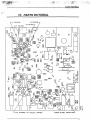
PEP on sync peaks (black video) with a lower audio sideband attenuation of better than 42 dB. The user may change the output power by adjusting C104 (see
Figure 4) to accommodate external power amplifier requirements. If power output
is increased above 1 watt PEP, amplifier distortion specifications are not guaranteed.
9