1
8.
Press RECEIVE/XM1T push-button switch to select transmit mode (latched In,
red LED lights).
9.
Begin transmitting. On your television receiver, check for video and audio signal quality and strength.
10. Adjust VIDEO GAIN AND AUDIO GAIN controls for signal quality and
strength ...
If you are using a Bird or equivalent power meter which ,reads average RF
power, it will read 0.6 watts minimum with a black video source. This is the
equivalent of one watt PEP on sync peaks.
7. RECEIVE MODE OPERA TION
1.
Press the RECEIVE/X~IT
switch to receive mode (latched out, LED off).
2.
Select transmit frequency:
F1 = 434.0 MHz, F2 = 439.25 MHz. Check that the F1/F2 switch is in the appropriate position.
Optional frequencies: 421.25, 426.25 or 439.25 MHz (if installed). Check that
F1/F2 switch is set to the appropriate position.
If you do not have a local oscillator crystal for the frequency yo~ wish to
receive, or the transmitting station's signal does not appear clearly, tum the RX
TUNE switch to VFO and adjust for best signal quality. The operating range of
the VFO is from 420 to 440 MHz.
8. SYSTEM DESCRIPTION
The VSB-70 provides all of the signal conditioning necessary to perform
NTSC video composite television transmission and reception in the 420 to 440
MHz band. The system is designed around a single conversion hardware architecture which utilizes the same television channel (3 or 4) for transmit and
receive signal conversion. Vestigial Sideband (VSB) filtering is utilized to minimize adjacent channel interference. The bandpass filter is tailored to the characteristics that a television receivefis designed to receive.
Two local oscillator crystal sockets are provided for transmission and reception modes, and a VFO is provided for reception of signals which' have drifted
such that crystal-controlled reception is difficult or impossible, or when different
transmit and receive frequencies are used, such as when using a repeater.
A linear Class A output amplifier has been optimized for one watt Peak Envelope Power (PEP.) on sync peaks with extremely low levels of intermodulation
distortion. Front-end reception is performed with a low-noise GaAsFET
preamplifier which provides the system with an overall receiver J:loisefigure of
less than 1.5 dB within the 420-445 MHz band
The functional operation of the transmit and receive modes is described
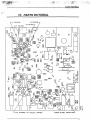
below. References are made to the component location diagram (Figure 4). The
block diagram (Figure 5) and schematic (Figure 6) may also be llseful.
8